施耐德SSR固态继电器
- 格式:pdf
- 大小:710.06 KB
- 文档页数:6

e-mail:**************User’s GuideSSRL240/SSRL660 SERIESSolid State RelaysShop online atIt is the policy of OMEGA to comply with all worldwide safety and EMC/EMI regulations that apply. OMEGA is constantly pursuing certification of its products to the European New Approach Directives. OMEGA will add the CE mark to every appropriate device upon certification.The information contained in this document is believed to be correct, but OMEGA Engineering, Inc. acceptsno liability for any errors it contains, and reserves the right to alter specifications without notice.WARNING: These products are not designed for use in, and should not be used for, patient-connected applications.PRECAUTIONSA number of essential safety precautions must be observed in the installation and use of a Solid State Relay (SSR).The SSRs should be installed and serviced by qualified technicians familiar with high voltage and current circuits. Note that an SSR has a small leakage current when the contacts are “open”. Normal failure condition is contacts “closed”. A special Fast Blowing I2T fuse and a mechanical interrupt switch are recommended in the load circuit. In certain applications a mechanical interrupt switch should be installed in the control circuit.GENERAL DESCRIPTIONThe Omega®Solid State Relays (SSR’s) are a series of single-pole, normally open, solid state switching devices with no moving parts, capable of tens of millions of cycles of operation. It is designed to control 120V, 240V or 480V (up to 660V) alternating current (VAC), and provides zero voltage switching and 2500VAC isolation between the load terminals and the control signal. A control signal (AC or DC input, depending on unit selected) causes the SSR to switch the ac load ON or OFF just as a conventional mechanical contact switch does but with none of the problems associated with moving contact relays, such as corrosion, pitting, arcing, radio frequency interference (RFI) and bounce. The result: much longer life for the SSR.The SSR is designed around a pair of SCR’s mounted on a heat-spreading metal base to eliminate thermal fatigue failures. To dissipate the heat developed naturally in an SSR due to a nominal voltage drop across the device, the SSR must be mounted on a Finned Heat Sink (FHS), or on a metal plate of adequate size (see Section 4). It is advisable to install an SSR where the ambient temperature is relatively low because its current-switching rating is decreased as its temperature increases.Control resistance heaters up to 40 kW use solid state relays in conjunction with lower-rated temperature controllers. Three-phase loads can be controlled using 2 or 3 SSR’s. Use 3 SSR’s for Y-phase loads using a neutral line. Three solid state relays are also used when there is no neutral load to provide redundancy and extra assurance of control. Two SSRs will control “delta” loads with no neutral line.1FINNED HEAT SINKS (FHS)The Finned Heat Sinks (FHS) are anodized, aluminum fabrications which come complete with tapped mounting holes, and screws to mount the SSR.FHS-1 and FHS-2 Heat SinkFHS-1 - FHS-2 Heat SinkFHS-6 Heat Sink (0.7°C/W Thermal Rating)FHS-6 Heat Sink2FUSE PROTECTIONThe load side of the SSR should be protected by a Fast-Blowing I 2T fuse.Recommended fuses and part numbers are given in below. Although asemiconductor relay is designed for virtually countless operation cycles, it can be destroyed by an over-voltage or a short circuit, unless protected adequately by the fast fuse.Table 3-1 shows the part numbers of the fuses and fuse blocks that can be used with each of the SSRs. Lower rated fast-blow fuses should be used if the current being controlled is below the rated capacity of the SSR. Bussman or equivalent fuses should be used. It is essential that a proper fast-blow (I 2T)fuse is used. SSR’s normal failure mode on overloaded circuits is closed contacts (ON-STATE).LEAKAGE CURRENTIn the OFF state, all SSRs have a small leakage current through their contacts,typically .1mA for 240V versions and .25mA for 660V versions. As a result, a voltage potential will always exist on the LOAD SIDE, even when the “contacts”are “open”. The voltage level is a function of the load resistance. In accordance with E = IR, the voltage level equals leakage current times load resistance.The voltage level will rise to FULL LINE VOLTAGE under NO LOAD (open circuit) or high resistance conditions. Under normal operating conditions,however, it is very small. A 120-Watt (W) load has a resistance of 1 ohm. With “open contacts”, a leakage current of 15mA will cause 15mV across the load (E = 15 mA ×1 ohm). A mechanical switch is recommended between the AC power source and the SSR to provide electric isolation for servicing the load.SSR Part Maximum Fuse Part Fuse Block Number Current Capacity Number Part NumberSSRL240AC1010 Amps ac KAX-10FB-1, FB-2, FB-3SSRL240AC2525 Amps ac KAX-25FB-1, FB-2, FB-3SSRL240AC50 50 Amps ac KAX-50 BS101SSRL240AC7575 Amps ac KAX-70BS101SSRL240AC100100 Amps ac KAX-100BS101SSRL240DC1010 Amps ac KAX-10FB-1, FB-2, FB-3SSRL240DC2525 Amps ac KAX-25FB-1, FB-2, FB-3SSRL240DC50 50 Amps ac KAX-50 BS101SSRL240DC7575 Amps ac KAX-70BS101SSRL240DC100100 Amps ac KAX-100BS101SSRL660AC5050 Amps ac KAX-50BS101SSRL660AC7575 Amps ac KAX-70BS101SSRL660AC100100 Amps ac KAX-100BS101SSRL660DC5050 Amps ac KAX-50BS101SSRL660DC7575 Amps ac KAX-70BS101SSRL660DC100100 Amps ac KAX-100BS1013O u t p u t -a c L o a dM a x . O f f -S t a t e L e a k a g e N o m i n a l a c L i n eN o m i n a l L o a d M a x . C o n t a c t (25°C m a x . a m b i e n t )M a x F o r w a r d M o d e l N o .V o l t a g eC u r r e n t V o l t a g eD r o p120V a c 240V a c 660V a c V o l t a g e D r o p S S R L 240A C 1010 A 0.1 m A 0.1 m A 1.35S S R L 240A C 2525 A 0.1 m A 0.1 m A 1.35S S R L 240A C 5024 t o 280V a c50 A 1.6V0.1 m A 0.1 m A N /A 1.35S S R L 240A C 7575 A 0.1 m A 0.1 m A 1.3S S R L 240A C 100100 A 0.1 m A 0.1 m A 1.3S S R L 240D C 1010 A 0.1 m A 0.1 m A 1.35S S R L 240D C 2525 A 0.1 m A 0.1 m A 1.35S S R L 240D C 5024 t o 280V a c50 A 1.6V0.1 m A 0.1 m A N /A 1.35S S R L 240D C 7575 A 0.1 m A 0.1 m A 1.3S S R L 240D C 100100 A 0.1 m A 0.1 m A 1.3S S R L 660A C 5050 A 0.25 m A 0.25 m A 0.25 m A 1.35S S R L 660A C 7548 t o 660V a c75 A 1.6V0.25 m A 0.25 m A 0.25 m A 1.3S S R L 660A C 100100 A 0.25 m A 0.25 m A 0.25 m A 1.3S S R L 660D C 5050 A 0.25 m A 0.25 m A 0.25 m A 1.35S S R L 660D C 7548 t o 660V a c75 A 1.6V0.25 m A 0.25 m A 0.25 m A 1.3S S R L 660D C 100100 A 0.25 m A 0.25 m A 0.25 m A 1.3E L E C T R I C A L S P E C IF I C A T I O N S4I n p u t -C o n t r o l S i g n a l C o n t r o l S i g n a l C o n t r o l S i g n a l C o n t r o l S i g n a l M a x I n p u t P e a k V o l t a g e *M o d e l N o .T y p eV o l t a g e T u r n -O n T u r n -O f f C u r r e n t (60 s e c . m a x )S S R L 240A C 10S S R L 240A C 25S S R L 240A C 50A C C o n t r o l S i g n a l90 t o 280V A C 90V A C 10V A C10m A 800VS S R L 240A C 75S S R L 240A C 100S S R L 240D C 10S S R L 240D C 25S S R L 240D C 50D C C o n t r o l S i g n a l 3 t o 32V D C 3V D C 1V D C 14m A 800VS S R L 240D C 75S S R L 240D C 90S S R L 660A C 50S S R L 660A C 75A C C o n t r o l S i g n a l90 t o 280V A C 90V A C 10V A C10m A1200VS S R L 660A C 100S S R L 660D C 50S S R L 660D C 75D C C o n t r o l S i g n a l4 t o 32V D C 4V D C1V D C14m A1200VS S R L 660D C 100E L E C T R I C A L S P E C IF I C A T I O N S *T r a n s i e n t s a b o v e t a b l e v a l u e s h o u l d b e s u p p r e s s e d .5The following SSRs are available from OMEGA Engineering.MOUNTING THE SSRThe SSR assembly (including heat sink) can be located close to the load,minimizing the lengths of power cables. The actuating device, such as atemperature controller, can then be located in an area more convenient to the operator.The FHS on which the SSR is to be mounted has been pre-drilled and tapped, and is supplied with mounting screws. The SSR is supplied with a thermallyconducting pad (attached). Mount the SSR securely to the heat sink with the mounting screws.The best location for the SSR is an open area with unrestricted air movement.The FHS should be mounted on a vertical surface with the fins vertical. If it is mounted with the fins horizontal, or on a horizontal surface, the thermalcoefficient must be re-dated by 20%. For air flow, allow at least 1⁄2in. clearance at each end and 1 in. on the sides.67OUTPUTSSR Dimensions (inches)SPECIFICATIONSGENERAL SPECIFICATIONS(1)PARAMETER ALL DEVICESOperating Temperature Range–20°to +80°CStorage Temperature Range–40°to +80°CInput to Output Isolation Voltage(2)4000 V rmsInput/Output to Ground Isolation Voltage2500 V rmsCapacitance Input to Output (Max)8 pFLine Frequency Range47 to 63 HzINPUT SPECIFICATIONS(1)PARAMETER SSRs DC SSRsControl Voltage90–280 VAC3–32 VDC (4)Drop Out Voltage10 Vrms 1.0 VDCMaximum Input Current(3)10 mA rms14 mADCTurn-On Time20 ms0.5 Cycle Max.(5)Turn-Off Time30 ms0.5 Cycle Max.Nominal Input Impedance Current RegulatedOUTPUT SPECIFICATIONS(1)PARAMETER SSRs UNITSMaximum On-State Current(6)10255075100Arms Minimum On-State Current5050100100100mArms Maximum 1-Cycle Surge(7)15030075010001200Apeak Maximum 1-Second Surge(8)3075150225300Apeak On-State Voltage Drop(9) 1.35 1.35 1.3 1.3 1.3Vpeak I2T (60 Hz)416937245850006000A2secFOOTNOTES(1)Specifications apply to T A–30 to +80°C unless otherwise noted.(2)At T A of 25°C for one second, maximum leakage 1 mA.(3)At maximum input voltage.(4)660V versions 4-32VDC(5)Zero cross over firing.(6)With relay properly mounted on an adequate heatsink.(7)At T A of 25°C, non-repetitive.(8)At T A of 25°C.(9)At T A of 25°C and maximum on-state current.8WARRANTY/DISCLAIMEROMEGA ENGINEERING, INC. warrants this unit to be free of defects in materials and workmanship for a period of 13 months from date of purchase. OMEGA’s Warranty adds an additional one (1) month grace period to the normal one (1) year product warranty to cover handling and shipping time. This ensures that OMEGA’s customers receive maximum coverage on each product.If the unit malfunctions, it must be returned to the factory for evaluation. OMEGA’s Customer Service Department will issue an Authorized Return (AR) number immediately upon phone or written request. Upon examination by OMEGA, if the unit is found to be defective, it will be repaired or replaced at no charge. OMEGA’s WARRANTY does not apply to defects resulting from any action of the purchaser, including but not limited to mishandling, improper interfacing, operation outside of design limits, improper repair, or unauthorized modification. This WARRANTY is VOID if the unit shows evidence of having been tampered with or shows evidence of having been damaged as a result of excessive corrosion; or current, heat, moisture or vibration; improper specification; misapplication; misuse or other operating conditions outside of OMEGA’s control. Components which wear are not warranted, including but not limited to contact points, fuses, and triacs.OMEGA is pleased to offer suggestions on the use of its various products. However, OMEGA neither assumes responsibility for any omissions or errors nor assumes liability for any damages that result from the use of its products in accordance with information provided by OMEGA, either verbal or written. OMEGA warrants only that the parts manufactured by it will be as specified and free of defects. OMEGA MAKES NO OTHER W ARRANTIES OR REPRESENTATIONS OF ANY KIND W HATSOEVER, EXPRESS OR IMPLIED, EXCEPT THAT OF TITLE, AND ALL IMPLIED W ARRANTIES INCLUDING ANY W ARRANTY OF MERCHANTABILITY AND FITNESS FOR A PARTICULAR PURPOSE ARE HEREBY DISCLAIMED. LIMITATION OF LIABILITY: The remedies of purchaser set forth herein are exclusive, and the total liability of OMEGA with respect to this order, whether based on contract, warranty, negligence, indemnification, strict liability or otherwise, shall not exceed the purchase price of the component upon which liability is based. In no event shall OMEGA be liable for consequential, incidental or special damages.CONDITIONS: Equipment sold by OMEGA is not intended to be used, nor shall it be used: (1) as a “Basic Component” under 10 CFR 21 (NRC), used in or with any nuclear installation or activity; or (2) in medical applications or used on humans. Should any Product(s) be used in or with any nuclear installation or activity, medical application, used on humans, or misused in any way, OMEGA assumes no responsibility as set forth in our basic WARRANTY/DISCLAIMER language, and, additionally, purchaser will indemnify OMEGA and hold OMEGA harmless from any liability or damage whatsoever arising out of the use of the Product(s) in such a manner.RETURN REQUESTS/INQUIRIESDirect all warranty and repair requests/inquiries to the OMEGA Customer Service Department. BEFORE RETU RNING ANY PRODU CT(S) TO OMEGA, PU RCHASER MU ST OBTAIN AN AU THORIZED RETU RN (AR) NU MBER FROM OMEGA’S CU STOMER SERVICE DEPARTMENT (IN ORDER TO AVOID PROCESSING DELAYS). The assigned AR number should then be marked on the outside of the return package and on any correspondence.The purchaser is responsible for shipping charges, freight, insurance and proper packaging to prevent breakage in transit.FOR WARRANTY RETURNS, please have the following information available BEFORE contacting OMEGA:1.Purchase Order number under whichthe product was PURCHASED,2.Model and serial number of the productunder warranty, and3.Repair instructions and/or specificproblems relative to the product.FOR NON-WARRANTY REPAIRS,consult OMEGA for current repair charges. Have the following information available BEFORE contacting OMEGA:1. Purchase Order number to cover theCOST of the repair,2.Model and serial number of the product,and3.Repair instructions and/or specificproblems relative to the product.OMEGA’s policy is to make running changes, not model changes, whenever an improvement is possible. This affords our customers the latest in technology and engineering.OMEGA is a registered trademark of OMEGA ENGINEERING, INC.© Copyright 2002 OMEGA ENGINEERING, INC. All rights reserved. This document may not be copied, photocopied, reproduced, translated, or reduced to any electronic medium or machine-readable form, in whole or in part, without the prior written consent of OMEGA ENGINEERING, INC.Where Do I Find Everything I Need for Process Measurement and Control?OMEGA…Of Course!Shop online at TEMPERATUREⅪߜThermocouple, RTD & Thermistor Probes, Connectors, Panels & AssembliesⅪߜWire: Thermocouple, RTD & ThermistorⅪߜCalibrators & Ice Point ReferencesⅪߜRecorders, Controllers & Process MonitorsⅪߜInfrared PyrometersPRESSURE, STRAIN AND FORCEⅪߜTransducers & Strain GagesⅪߜLoad Cells & Pressure GagesⅪߜDisplacement TransducersⅪߜInstrumentation & AccessoriesFLOW/LEVELⅪߜRotameters, Gas Mass Flowmeters & Flow ComputersⅪߜAir Velocity IndicatorsⅪߜTurbine/Paddlewheel SystemsⅪߜTotalizers & Batch ControllerspH/CONDUCTIVITYⅪߜpH Electrodes, Testers & AccessoriesⅪߜBenchtop/Laboratory MetersⅪߜControllers, Calibrators, Simulators & PumpsⅪߜIndustrial pH & Conductivity EquipmentDATA ACQUISITIONⅪߜData Acquisition & Engineering SoftwareⅪߜCommunications-Based Acquisition SystemsⅪߜPlug-in Cards for Apple, IBM & CompatiblesⅪߜDatalogging SystemsⅪߜRecorders, Printers & PlottersHEATERSⅪߜHeating CableⅪߜCartridge & Strip HeatersⅪߜImmersion & Band HeatersⅪߜFlexible HeatersⅪߜLaboratory HeatersENVIRONMENTALMONITORING AND CONTROLⅪߜMetering & Control InstrumentationⅪߜRefractometersⅪߜPumps & TubingⅪߜAir, Soil & Water MonitorsⅪߜIndustrial Water & Wastewater TreatmentⅪߜpH, Conductivity & Dissolved Oxygen InstrumentsM3813/0502。
输入(控制)参数(TA=25℃)其它参数(TA=25℃)输入电压范围(直流)3-32VDC介质耐压4000VAC(输入与输出间)2500VAC (输入、输出与底座间)确保接通电压(直流) 3.0VDC 绝缘电阻1000M Ω(500VDC )确保关断电压(直流) 1.0VDC 工作温度范围-30℃~80℃输入电流(典型值)18mA 储存温度范围-30℃~100℃输入电流(最大值)25mA 重量约20g反极性电压(直流)-32VDC输出(负载)参数(TA=25℃)2FD11052FD22052FD4005输出电压范围5~110VDC 5~220VDC 5~400VDC 最大瞬态电压120Vpk 260Vpk 440Vpk 最大输出漏电流1mA1mA1mA最大输出压降 1.0Vrms最大负载电流3A 、5A 、10A (强迫风冷)最大浪涌电流(10ms )额定电流的10倍最小功率因数0.5最大接通时间1ms 最大关断时间8ms 断态电压指数上升率dv/dt 100V/μs 最小工作电流30mA订货标记示例性能曲线图S S R2F48 03最大负载电流与环境温度特性图()5A环境温度(℃)最大()A 最大负载电流与环境温度特性图()3A3.02.41.81.20.6环境温度(℃)最大()A最大负载电流与环境温度特性图() 10A环境温度(℃)讅︳題磢︳ 髛︳ 竲簘詝貆祡︳ 鐌羮︳ 鱹︳ ()A -20 0 20 4安装孔尺寸图使用说明:1、实际负载电流≥5A时必须使用风冷对SSR进行散热冷却。
2、固态继电器的自身功耗产生的热量需要通过外壳散热,如果固态继电器周围散热条件很差,则输出负载电流应降额。
3、当两只或以上数量固态继电器并排安装时,应留有足够的间距(10mm以上)。
4、当多只固态继电器共用一个控制电源时,输入控制端可以串联或并联使用;但必须保证每只固态继电器有足够的输入驱动电流。
5、使用于感性负载时,将会出现高瞬间电压和浪涌电流施加在输出端,可能导致固态继电器误导通或损坏。
固态继电器的技术参数工作原理及其选型固态继电器(Solid State Relay,SSR)是一种使用半导体器件作为控制元件,替代传统电磁继电器的电器开关装置。
固态继电器具有快速响应、可靠性高、抗干扰能力强等特点,广泛应用于自动化控制系统、电力系统、机械设备等领域。
下面将对固态继电器的技术参数、工作原理及其选型进行详细介绍。
一、固态继电器的技术参数1.额定电压:固态继电器的额定电压指的是继电器能够承受的最大电压。
常见的额定电压有3-32VDC、5-60VDC、12-380VAC等。
2.额定电流:固态继电器的额定电流指的是继电器能够承受的最大电流。
常见的额定电流有10A、25A、40A、80A等。
3.输入电阻:固态继电器的输入电阻是指在控制端接入继电器时,继电器对输入信号的阻抗大小。
输入电阻越大,控制电流所消耗的功率越小。
4.输出电阻:固态继电器的输出电阻是指在输出端的负载上产生的电阻。
输出电阻越小,继电器输出的电压越稳定。
5.工作温度范围:固态继电器的工作温度范围是指继电器能够正常工作的温度范围。
一般情况下,工作温度范围为-40℃到+80℃之间。
二、固态继电器的工作原理当控制电路输入的电流大于等于继电器的激活电流时,继电器将被激活并输出电压。
反之,如果输入电流小于继电器的激活电流,则继电器保持断开状态。
三、固态继电器的选型在选型固态继电器时,需要考虑以下几个方面的因素:1.负载类型:根据实际应用需求选择适合的负载类型,固态继电器可用于交流负载和直流负载。
2.额定电压和额定电流:根据负载的额定电压和额定电流选择对应的固态继电器。
额定电压和额定电流应略大于负载的实际值,以保证稳定可靠的开关动作。
3.工作温度范围:根据实际工作环境的温度范围选择适合的固态继电器。
4.响应时间:对于需要快速响应的应用场合,需要选择响应时间较短的固态继电器。
5.安装方式:根据实际安装方式选择合适的固态继电器,可以是面板安装、导轨安装或者插座安装。
固态继电器原理及接线方法固态继电器(Solid State Relay,简称SSR)是一种非接触式的电力控制元件,它能够将微弱的控制信号转换成相应的高功率负载输出信号,实现电路的开关控制。
本文将介绍固态继电器的原理以及常见的接线方法。
固态继电器由输入控制电路、输出负载电路和隔离传导电路三部分组成。
输入控制电路通常由光电耦合器和触发电路构成,它可以实现高低电平的转换,将来自低压电路的微弱控制信号转换为高压电路的驱动信号。
输出负载电路由一对双向可控硅三极管和电流保护电路构成,它可以根据输入控制信号的变化打开或关闭电路,并将高功率的负载电流传导至外部负载。
隔离传导电路则起到隔离输入与输出电路的作用,避免输入与输出电路之间的电气干扰。
1.直流控制接线:直流控制接线方式包括无源式和有源式两种方式。
(1)无源式直流控制接线方法:这种接线方法是将固态继电器的控制端与直流信号源相连,其中直流信号源可以是直流电源、开关、传感器等。
具体接线方法为:将正极(+)与控制端(+)相连,负极(-)与控制端(-)相连。
在这种方式下,只需要将直流信号源的电压高于触发电压即可激活固态继电器。
此时,当外部触发电路通电,通过光电耦合器输出的光电信号就能够导通SSR的输出端,实现电路的开关控制。
(2)有源式直流控制接线方法:这种接线方法是在无源式直流控制接线的基础上加入控制电源,以增强驱动能力和稳定性。
具体接线方法为:将固态继电器的控制端与控制信号源相连,控制信号源可以是可控硅、继电器、PLC等。
在这种方式下,通过控制信号源的开关状态,控制电源的导通与否,从而实现固态继电器的驱动。
2.交流控制接线:交流控制接线方式包括零火控制接线和触发控制接线两种方式。
(1)零火控制接线方法:这种接线方法是将固态继电器的控制端与零线相连,控制端不接接地线。
具体接线方法为:将控制端与电源的零线相连,在这种方式下,固态继电器的输出信号与交流输入电源的零线同步,从而实现电路的控制。
SSR固态继电器的原理
固态继电器首要由输入(操控)电路,驱动电路和输出(负载)电路三有些构成。
固体继电器的输入电路是为输入操控信号供给一个回路,使之变成固体继电器的触发信号源。
固体继电器的输入电路多为直流输入,单个的为沟通输入。
直流输入电路又分为阻性输入和恒流输入。
阻性输入电路的输入操控电流随输入电压呈线性的正向改动。
恒流输入电路,在输入电压抵达必定值时,电流不再随电压的添加而显着增大,这种继电器可适用于恰当宽的输入电压计划。
固体继电器的驱动电路能够包含隔绝耦合电路、功用电路和触发电路三有些。
隔绝耦合电路,如今多选用光电耦合器和高频变压器两种电路办法。
常用的光电耦合器有光-三极管、光-双向可控硅、光-二极管阵列(光-伏)等。
高频变压器耦合,是在必定的输入电压下,构成约十MHz的自激振荡,经过变压器磁芯将高频信号传递到变压器次级。
功用电路可包含检波整流、过零、加快、维护、闪现等各种功用电路。
触发电路的效果是给输出器材供给触发信号。
固体继电器的输出电路是在触发信号的操控下,完毕固体继电器的通断切换。
输出电路首要由输出器材(芯片)和起瞬态按捺效
果的吸收回路构成,有时还包含反响电路。
如今,各种固体继电器运用的输出器材首要有晶体三极管(Transistor)、单向可控硅(Thyristor 或SCR)、双向可控硅(Triac)、MOS场效应管(MOSFET)、绝缘栅型双极晶体管(IGBT)等。
ssr固态继电器工作原理SSR固态继电器(Solid-State Relay)是一种使用半导体器件来实现电气隔离和电路开关的电子元件。
相比传统的机械继电器,SSR 具有响应速度快、寿命长、体积小、耐振动、无噪音等优点。
本文将从SSR固态继电器的工作原理、结构组成和应用领域等方面进行详细介绍。
一、工作原理SSR固态继电器的工作原理基于半导体器件的导通与截止特性。
它由输入控制电路和输出功率电路两部分组成。
输入控制电路接收外部的控制信号,通过对控制电路中的半导体器件进行驱动,使得输出功率电路中的半导体器件导通或截止,从而实现对输出电路的控制。
具体来说,输入控制电路通常由光耦隔离器、驱动电路和触发电路组成。
当输入控制信号到达时,光耦隔离器将信号光电转换,驱动电路将光电信号转换为电流或电压信号,进而通过触发电路对输出功率电路进行控制。
输出功率电路由半导体器件(如晶闸管、三极管)和负载组成。
当输入控制电路中的半导体器件导通时,输出功率电路中的半导体器件也将导通,从而使得负载得到电源的供电;当输入控制电路中的半导体器件截止时,输出功率电路中的半导体器件也将截止,负载将不再接收电源供电。
二、结构组成SSR固态继电器的基本结构通常包括输入控制电路、输出功率电路和隔离层。
其中,输入控制电路主要负责接收和处理外部的控制信号;输出功率电路主要负责对负载进行电源的控制;隔离层则起到隔离输入控制电路和输出功率电路的作用,保证两者之间的电气隔离。
在输入控制电路中,光耦隔离器起到了关键作用。
光耦隔离器通常由发光二极管(LED)和光敏三极管(光电晶体管)构成。
当输入控制信号到达时,LED被激活,发出特定的光信号;光敏三极管根据接收到的光信号的强弱,产生相应的电流或电压信号。
输出功率电路中的半导体器件通常由晶闸管或三极管构成。
晶闸管具有导通电流大、耐压能力强的特点,适用于大功率负载的控制;而三极管则适用于小功率负载的控制。
这些半导体器件能够通过输入控制电路的驱动来实现导通或截止状态,从而控制负载的电源供应。

Solid state relaysSSR固态继电器以触发形式,可分为零压型(Z)和调相型(P)两种。
在输入端施加合适的控制信号VIN时,P型SSR立即导通。
当VIN撤销后,负载电流低于双向可控硅维持电流时(交流换向),SSR关断。
Z型SSR内部包括过零检测电路,在施加输入信号VIN时,只有当负载电源电压达到过零区时,SSR才能导通,并有可能造成电源半个周期的最大延时。
Z型SSR关断条件同P型,但由于负载工作电流近似正弦波,高次谐波干扰小,所以应用广泛。
先锋公司电子厂SSR由于采用输出器件不同,有普通型(S,采用双向可控硅元件)和增强型(HS,采用单向可控硅元件)之分。
当加有感性负载时,在输入信号截止t1之前,双向可控硅导通,电流滞后电源电压90O(纯感时)。
t1时刻,输入控制信号撤销,双向可控硅在小于维持电流时关断(t2),可控硅将承受电压上升率dv/dt很高的反向电压。
这个电压将通过双向可控硅内部的结电容,正反馈到栅极。
如果超过双向可控硅换向dv/dt指标(典型值10V/s,将引起换向恢复时间长甚至失败。
单向可控硅(增强型SSR)由于处在单极性工作状态,此时只受静态电压上升率所限制(典型值200V/s),因此增强型固态继电器HS系列比普通型SSR的换向dv/dt指标提高了520倍。
由于采用两只大功率单向可控硅反并联,改变了电流分配和导热条件,提高了SSR输出功率。
增强型SSR在大功率应用场合,无论是感性负载还是阻性负载,耐电压、耐电流冲击及产品的可靠性,均超过普通固态继电器,并达到了进口产品的基本指标,是替代普通固态继电器的更新产品。
固态继电器的应用S系列固态继电器,HS系列增强型固态继电器、可以广泛用于:计算机外围接口装置,恒温器和电阻炉控制、交流电机控制、中间继电器和电磁阀控制、复印机和全自动洗衣机控制、信号灯交通灯和闪烁器控制、照明和舞台灯光控制、数控机械遥控系统、自动消防和保安系统、大功率可控硅触发和工业自动化装置等。

固态继电器(SSR)的定义■固态继电器(SSR)的定义●SSR和有接点继电器的不同所谓SSR,是固态继电器(Solid State Relay)的简称,是⽆可动接点部分的继电器(⽆接点继电器)。
在动作上与有接点继电器相同,但是该继电器使⽤半导体闸流管、晶闸管开关元件、⼆极管、晶体管等半导体开关元件。
另外也使⽤名为光电耦合器的光半导体,使其输⼊输出绝缘。
光电耦合器的特点是⽤光的信号在绝缘空间中进⾏传送,所以绝缘性更好,传送速度也更快。
SSR是⽤⽆接点的电⼦零件制造的,⽐有接点的有很多优点。
其中最⼤的优点是,不会像有接点继电器⼀样因开关⽽损耗接点。
特别是:●可以对应⾼速、⾼频率开关●没有接触不良●发⽣⼲扰⼩●没有动作⾳等,适⽤于⼴泛的领域。
固态继电器(SSR)的构成固态继电器(SSR)的构成固态继电器(SSR) (交流负载开关的代表⽰例)固态继电器(SSR) (交流负载开关的代表⽰例)电磁继电器 (EMR:Electro Magnetic Relay)向线圈施加输⼊电压,使其发⽣电磁⼒,移动可动铁⽚,从⽽切换接点。
不仅可在控制柜上使⽤,还可⽤于其他范围。
⽽且原理简单可低成本加⼯。
电磁继电器(EMR:Electro Magnetic Relay)●SSR的控制(ON/OFF控制、循环控制、相位控制)ON/OFF控制接受温控器的电压输出信号,通过开关SSR来控制加热器的ON/OFF。
在电磁继电器中也可进⾏相同的控制,但是以数秒间隔控制ON/OFF,使⽤数年时需要SSR。
循环控制(G32A-EA)以0.2秒(固定)为控制周期。
其⽅式是使其在0.2秒内ON/OFF,从⽽控制输出电⼒。
接受温控器的电流输出4~20mA来控制循环控制中的注意点进⾏循环控制时,每秒钟接通电源5次(控制周期为 0.2S)。
由于变压器负载中的接通电流⾮常⼤(通常电流的10倍左右)(1)SSR的额定没有余量导致SSR的破坏。
(2)负载电路上的断路器发⽣触发。
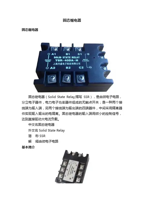
固态继电器固态继电器固态继电器(Solid State Relay,缩写SSR),是由微电子电路,分立电子器件,电力电子功率器件组成的无触点开关;是一种两个接线端为输入端,另两个接线端为输出端的四端器件,中间采用隔离器件实现输入输出的电隔离。
固态继电器的输入端用微小的控制信号,达到直接驱动大电流负载。
中文名固态继电器外文名Solid State Relay简称SSR解释由微电子电路基本简介固态继电器固态继电器是具有隔离功能的无触点电子开关,在开关过程中无机械接触部件,因此固态继电器除具有与电磁继电器一样的功能外,还具有逻辑电路兼容,耐振耐机械冲击,安装位置无限制,具有良好的防潮防霉防腐蚀性能,在防爆和防止臭氧污染方面的性能也极佳,输入功率小,灵敏度高,控制功率小,电磁兼容性好,噪声低和工作频率高等特点。
固态继电器专用的固态继电器可以具有短路保护,过载保护和过热保护功能,与组合逻辑固化封装就可以实现用户需要的智能模块,直接用于控制系统中。
固态继电器如今已广泛应用于计算机外围接口设备、恒温系统、调温、电炉加温控制、电机控制、数控机械,遥控系统、工业自动化装置;信号灯、调光、闪烁器、照明舞台灯光控制系统;仪器仪表、医疗器械、复印机、自动洗衣机;自动消防,保安系统,以及作为电网功率因素补偿的电力电容的切换开关等等,另外在化工、煤矿等需防爆、防潮、防腐蚀场合中都有大量使用。
如何选择SSR的型号规格主要是选取适当的额定电流的固态继电器(SSR)除特别说明以外,整流、可控等功率模块亦然。
根据不同的负载类型来选用SSR的额定电流。
阻性负载、感性负载和容性负载在刚起动时瞬时电流较大。
即使是纯阻性,由于具有正温度系数,冷态时电阻值较小,因而有较大的起动电流。
电炉刚接通时电流为稳定时的1.3—1.4倍。
白炽灯接通时电流为稳态10倍。
有些金属卤化物灯不但开启时间长达10分钟,而且有高达100倍稳态时的脉冲电流。
异步电动机起动电流为额定值的5—7倍,直流电机起动电流还要大。
固态继电器电气符号及字母表示
【一、固态继电器简介】
固态继电器(Solid State Relay,简称SSR)是一种无触点、电子开关,它具有高输入阻抗、低功耗、长寿命、高可靠性等优点。
固态继电器广泛应用于各种电子设备、自动化控制系统和工业电路中,以实现信号的放大、隔离、切换等功能。
【二、固态继电器电气符号】
【1.通用的电气符号】
固态继电器的通用电气符号为一个长方形,内部包含一个垂直的线,代表开关状态。
长方形的一侧带有箭头,表示信号的传输方向。
【2.特殊类型的电气符号】
对于具有特殊功能的固态继电器,如双向固态继电器,其电气符号在通用符号的基础上,增加了一个水平线,表示两个开关状态之间的切换。
【三、字母表示】
【1.英文表示】
固态继电器的英文表示为Solid State Relay,简称SSR。
【2.中文表示】
固态继电器在中文中简称“固态继电器”,也可以表示为“无触点开关”或“电子开关”。
【四、固态继电器在电路中的应用】
固态继电器在电路中的应用主要包括以下几个方面:
1.信号放大:固态继电器可以实现小信号到大信号的放大,从而驱动大功率负载。
2.信号隔离:固态继电器具有良好的隔离性能,可以防止信号干扰和电磁泄漏。
3.信号切换:固态继电器可以在不同电路之间进行信号切换,实现多种控制功能。
4.保护电路:固态继电器可应用于过压、过流等保护电路,确保电路安全运行。
【五、总结】
固态继电器作为一种无触点电子开关,具有很高的可靠性和实用性。
了解其电气符号、字母表示以及在电路中的应用,对于电子工程师和电气工程师来说具有重要意义。
固态继电器工作原理及接线使用方法固态继电器(Solid State Relay,简称SSR)是一种在控制信号电路与被控制电路之间进行电气隔离的电子开关装置,它通过半导体器件(如光电转换器、晶闸管、场效应管等)来实现对电流的控制。
相比传统的电磁继电器,固态继电器具有体积小、寿命长、响应快、耐冲击、可靠性高等优点,广泛应用于自动化控制领域。
1.输入控制信号:固态继电器的控制端通常为一个输入电压信号。
当控制电压处于工作电压范围内时,控制电路中的激活电源会为SSR提供足够的电流和电压以使其导通,完成输入信号的传输。
2. 光电耦合器:固态继电器内部通常包含一个光电耦合器(Optocoupler),其由一个发光二极管(LED)和一个光敏三极管(Phototransistor)组成。
当输入电压导通时,LED会发出红外线,并被光敏三极管接收。
3.内部开关:光电耦合器接收到红外信号后,光敏三极管会根据其光敏元件的导通程度改变输出电阻,进而控制内部开关,通常为晶闸管或场效应管,的状态。
当光敏三极管导通时,内部开关导通,实现电流的通断控制。
4.输出负载:固态继电器的输出端通常为一个负载电源,其与内部开关相连。
当内部开关导通时,负载电源与负载电器连接,使电流得以通过;当内部开关断开时,负载电器与负载电源断开,电流停止流过。
1.输入端接线:控制端一般需要外部输入一个控制信号电压,常用的控制信号电压有3~32VDC(直流)和85~250VAC(交流)两种。
-直流输入:如果采用直流输入,可以使用一个稳压电源和一个电阻作为限流器,将控制端的正极与稳压电源正极相连,负极则接入控制信号输入端并与稳压电源的负极相连。
-交流输入:如果采用交流输入,可以直接将控制信号输入端接入交流电压。
2.输出端接线:输出端一般用于控制电流的开断,其接线方法根据实际应用的负载类型而有所不同。
-直流负载:如果负载是直流电压,可以将正极与SSR输出端连接,负极与负载相连。
固态继电器SSR控制和驱动方法图解SSR是固态继电器的简称,固态继电器一种无机械触点的电子开关元件,它具有掌握敏捷,牢靠性高,寿命长,在通与断的时间不会产生电火花,无噪声,开关速度快,工作频率高,抗干扰力量强等优点,SSR的另一个特点是驱动电流(或电压)小,给输入端加一个很小的信号,就可以实现对被掌握系统的掌握。
(下文全部固态继电器均用SSR来表示)作为无机械触点的开关功能元件,SSR的基本使用框图如下:SSR的输入掌握方法和电路SSR的类型,型号许多,所以它的输入掌握方法和掌握电路也相应较多。
SSR之间的共同特点是驱动电流或驱动电压很小,输入一个很小的信号就可以时间对SSR输出状态通,断的掌握。
假如要实现有效而牢靠的掌握,其输入信号必需达到一个给定值。
对输入回路工作电流的要求,推举值为5-10mA时开通,小于1mA时关断,对于输入端工作电压的要求,一般状况下开通时不低于3V,关断时小于1V,当然,因产品特性不同伙厂家不同,对输入电流或电阻值的要求是会有差异的。
因此在使用和设计电路的时候,可以依据SSR的类型,规格和使用场合来进行选择和设计,下面就介绍一些基本的输入端掌握方法和电路。
1.SSR触点掌握方式由一组机械触点直接掌握电路,如下图,图中的S可以是机械开关,也可以是继电器触点货电子开关电路。
2.采纳三极管掌握SSR的通断SSR可用NPN型货PNP型晶体三极管直接掌握其输入端(如下图a,b所示),在图a电路中,平常VT导通,SSR出于接通状态,当有脉冲时,SSR断开,在图b所示电路中,平常电路中,平常VT截止,SSR呈断开状态,当有脉冲时,SSR接通。
对于一般的SSR,要求输入的最小工作电压为3V(接通),若低于1V,则SSR关断。
3.采纳TTL数字集成电路驱动SSR 用TTL数字继承电路掌握SSR通断的电路,如下图:4.采纳CMOS数字集成电路驱动SSR CMOS器件的输入阻抗高,输出规律电平摇摆幅大(凹凸电平值接近电源电压),很适合与SSR 和其他电路协作,但CMOS器件的静态功耗和动态功耗(静态功耗仅约为10nW,动态功耗为几毫瓦)。
SSR固态继电器的工作原理1. 继电器的基本原理继电器是一种电控制电器的装置,它通过控制一个或多个开关来实现对电路的开关控制。
传统的机械继电器由线圈、触点和弹簧组成。
当线圈通电时,产生磁场吸引触点闭合,断开或连接电路。
然而,机械继电器存在一些问题,如噪音、机械磨损、寿命有限等。
为了解决这些问题,固态继电器(Solid State Relay, SSR)应运而生。
2. SSR固态继电器的基本结构SSR由输入端、输出端和驱动部分组成。
输入端通常是一个控制信号(如低功率直流信号),输出端则用于控制高功率负载(如交流负载)。
驱动部分包括光耦隔离、触发芯片和功率元件。
3. 光耦隔离光耦隔离是SSR中重要的一部分。
它通过光学传感技术将输入端与输出端进行了隔离,避免了直接接触高压高功率负载。
光耦隔离由发光二极管(LED)和光敏三极管(光电晶体管)组成。
当输入端的控制信号施加到LED上时,LED会发出红外线。
光敏三极管中的光电二极管感受到红外线后,产生电流,从而控制输出端的开关。
4. 触发芯片触发芯片是SSR中的核心部件,负责控制和调节输出端的开关状态。
触发芯片通常由一个集成电路(IC)构成。
触发芯片通过对输入端信号进行处理,产生相应的控制信号,以驱动功率元件切换输出端。
触发芯片还能实现一些额外功能,如过流保护、过温保护等。
5. 功率元件功率元件是SSR中用于切换高功率负载的部分。
它通常采用半导体器件(如晶闸管、三极管、场效应晶体管等)替代传统机械式继电器中的触点。
当触发芯片产生相应的控制信号时,功率元件会切换通断状态,从而实现对负载电路的控制。
6. 工作原理SSR的工作原理可以简单描述为以下几个步骤:1.输入端的控制信号施加在光耦隔离中的LED上,LED发出红外线。
2.光敏三极管中的光电二极管感受到红外线后,产生电流。
3.电流经过触发芯片进行处理,产生相应的控制信号。
4.控制信号驱动功率元件切换通断状态,控制输出端的负载电路。
输入(控制)参数(TA=25℃)其它参数(TA=25℃)输入电压范围(直流)3-32VDC 介质耐压4000V AC(输入与输出间)2500V AC(输入、输出与底座间)确保接通电压(直流) 3.0VDC 绝缘电阻1000MΩ(500VDC)确保关断电压(直流) 1.0VDC 工作温度范围-30℃~80℃输入电流(典型值) 12mA 储存温度范围-30℃~100℃输入电流(最大值)15mA 重量约100g反极性电压(直流)-32VDC输出(负载)参数(TA=25℃)输出电压范围40~280V AC 40~480V AC 90~660V AC最大瞬态电压800Vpk 1100Vpk 1500Vpk最大输出漏电流5mA 5mA 5mA最大输出压降 1.5Vrms最大负载电流10A最大浪涌电流(10ms)额定电流的8倍最小功率因数0.5最大接通时间1/2周期+1ms最大关断时间1/2周期+1ms断态电压指数上升率dv/dt 100V/μs特性◆光电隔离◆可提供透明防护盖◆4000V介质耐压◆过零或随机导通开关◆面板安装◆SCR反并联输出◆内置RC吸收回路◆LED指示工作状态◆环保产品(符合ROHS要求)产品介绍:SSR-DA系列为小型大功率固态继电器,输入控制电压为3-32VDC,输出采用单向可控硅反并联,耐dv/dt能力高,输出负载电压范围40-660V AC。
极大的满足了客户各种不同场合的需要。
该产品输入与输出之间采用光电隔离,其介质耐压达到4000V AC。
采用环氧树脂灌封,外型尺寸:57.4mm×45.7mm×23mmSSR-DA系列固态继电器被广泛应用在电炉温控、橡胶塑料机械、印刷机械、包装机械、喷泉控制、数控机床、舞台灯光等工业自动化领域。
杭州国晶电子科技有限公司+86(571)56862135杭州国晶电子科技有限公司 +86(571)56862135 订货标记示例性能曲线图0 100 200 300 400 500负载电压()VAC 1115漏电流(mA)漏电流与负载电压特性图(@25℃)最大负载电流与环境温度特性图()10A 环境温度(℃)最大负载电流()A -20 0 20 4 60 800带散热器I-50不带散热器外型安装尺寸图:使用说明:1、实际负载电流≥5A时必须使用散热器或安装在具有相应散热效果的金属底板上,并且固态继电器散热底板与安装面之间涂上导热硅脂。
中间继电器是一种继电保护元件,其工作原理:由固定铁芯、动铁芯、弹簧、动触点、静触点、线圈、接线端子和外壳组成。
线圈通电,动铁芯在电磁力作用下动作吸合,带动动触点动作,使常闭触点分开,常开触点闭合;线圈断电,动铁芯在弹簧的作用下带动动触点复位。
中间继电器用在自动控制系统中目的有以下几种:一、增加触点的数量,用于IO输出控制(常用的8针中间继电器都有2路NC和2路NO);二、隔离开关作用,与交流接触器作用一样,可以通过小电压控制大电压的通断,比如说控制电压是DC24V,需要控制AC220V电路的通断就可以使用中间继电器,但是需要注意中间继电器的触点允许通过电流较小,这也是中间继电器与交流接触器;三、两个控制系统进行握手信号时使用无源信号,通常选择使用中间继电器,一个系统控制中间继电器触点的通断,另一个系统根据自我本身输入信号电平要求进行连接,这样可以有效的避免两个系统之前的电源干扰;四、与按钮配合行成自锁,也就是常说的一键启动功能,按钮与中间继电器常开端进行并联,按钮按下线圈得电,常开触点闭合进行自锁。
比较常用的有固态继电器,热继电器和时间继电器:(1)固态继电器:电气符号:SSR固态继电器是有半导体材料组成,简称SSR。
常用的为4个引脚,2个引脚对应线圈,2个引脚对应开关的常开端;相比较中间继电器而言固态继电器的优点:1.对应电气柜震动带来的影响小,因为他不是触点膜片组成的;2.反应时间快,只有几个ms;3.触发时无触点火花,可以用于防爆情况;4.受外界电磁干扰较小;但是需要注意的是由于半导体材料对使用环境温度要求比较高(2)时间继电器:电气符号KT时间继电器是在线圈通电或者断开一定时间后对应的触点才会动作,由于这种特性时间继电器一般用于以时间为函数的电动机起动过程控制。
(我观察到机械臂控制柜中时间继电器,是否是用于保护控制电路,防止电机在启动和停止是方向电流对控制系统造成影响?具体作用不是很清楚,大家是否告知一下)(3)热继电器:电气符号FR热继电器用于保护电路过载,原理是工作原理是电流入热元件的电流产生热量,使金属膜片形变导致电路断开;一般用于保护电机运动过载;通过上述内容的介绍,相信大家都有一定的认识,同时如有这方面的问题需要了解,可以在线咨询南京首科机电有限公司官网或拨打热线询问。
固态继电器使用方法固态继电器(Solid State Relay,简称SSR)是一种电子开关设备,用于控制高电压或高电流负载。
与传统的机械继电器相比,固态继电器具有快速响应、寿命长、噪音小、体积小、可靠性高等优势。
以下是固态继电器的使用方法:1.确认负载和输入电压要求:在选择固态继电器之前,首先需要确定所要控制的负载类型和工作电压范围。
负载类型可以是交流(AC)或直流(DC),并且注意不要超过固态继电器的额定电流和额定电压。
2.连接固态继电器:将输入端(控制信号)连接到驱动电源,通常为低电平或低电流的信号源。
固态继电器通常有驱动电流范围,确保输入信号在范围内。
将负载连接到输出端,确保正确接线,以避免错误操作。
3.热沉散热器的使用:若要控制高功率负载或频繁开关负载,可能会产生较大的热量。
在这种情况下,使用热沉散热器来帮助散发热量以确保固态继电器的可靠性和寿命。
4.隔离输入和输出:固态继电器通常具有隔离功能,即输入和输出之间具有电气隔离。
这样可以防止不同系统之间的电气干扰,并提高安全性。
确保正常工作时输入和输出之间没有短路。
5.控制信号和状态指示:控制固态继电器的开关信号可以是数字脉冲、逻辑电平、变阻器等。
在选择控制信号时,需确保信号源与固态继电器的驱动电流适配。
同时,确认固态继电器的工作状态可通过指示灯或状态信号获取。
6.防护措施:合理使用过流保护、过压保护以及电源滤波器等辅助设备,以确保固态继电器正常工作和负载安全。
此外,在进行维修或更换固态继电器时,应断开电源,避免触电危险。
7.测试和验证:在安装固态继电器后,进行相关的测试和验证以确保其可靠性和正确性。
测试可以包括使用控制信号,观察负载电动势表现、固态继电器的响应时间和温度升高情况等。
总结来说,固态继电器的使用方法包括选型、连接、散热、隔离、控制信号、状态指示、防护措施、测试和验证等。
正确使用固态继电器可以确保负载的正常工作,延长设备寿命,并提高系统的可靠性和安全性。
产品介绍
Zelio Relay - 固态继电器
SSR 固态继电器
SSR 固态继电器型号包括:p 面板安装继电器: SSR P p 5导轨安装继电器: SSR D
继电器说明
SSR P 面板安装继电器1 2 x Ø4.5固定孔。
2连接端子。
3螺钉连接端子。
4绿色输入LED 指示器。
5必须安装在继电器背部的散热片。
SSR D 5 导轨安装继电器1面板安装用吊耳 2整体安装的散热槽3连接端子4螺钉连接端子
5绿色输入LED 指示器65导轨安装用支架
13
421
5
134
25
6
1
特性Zelio Relay - 固态继电器
SSR P 固态继电器
面板安装
特性(续)Zelio Relay - 固态继电器
SSR P 固态继电器
面板安装
特性Zelio Relay - 固态继电器
SSR D 固态继电器
5导轨安装
SSR PCDS pppp SSR PCDM pppp 散热片
最小包装数10
SSR PP8S pppp SSR PCDS pppp SSR PCDM pppp
0.1
SSR AT1
0.011
SSR PCDS25A1
SSR DCDS10A1
SSR DCDS45A1
SSR AH1
SSR AT1
(1) Ø4.4 x 5.5延长孔(1) Ø4.4 x 5.5延长孔。