计算材料学-14-1
- 格式:pdf
- 大小:4.55 MB
- 文档页数:57
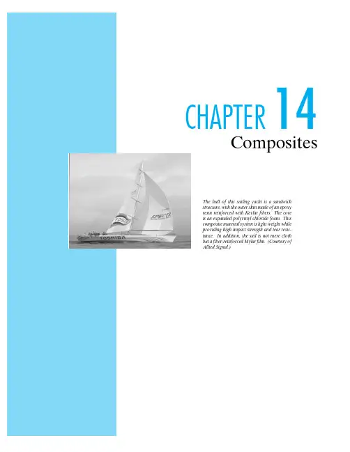
CHAPTER14CompositesThe hull of this sailing yacht is a sandwich structure,with the outer skin made of an epoxy resin reinforced with Kevlar fibers.The core is an expanded polyvinyl chloride foam.This composite material system is light weight while providing high impact strength and tear resis-tance.In addition,the sail is not mere cloth but a fiber-reinforced Mylar film.(Courtesy of Allied Signal.)Figure14-1Glassfibers to be used for reinforcement in afiber-glass composite.(Courtesy of Owens-Corning FiberglasCorporation)Figure14-2The glassfiber reinforcement in afiberglass composite is clearly seen in a scanning electron microscope image of a fracturesurface.(Courtesy of Owens-Corning Fiberglas Corporation)(a)(b)(c)Figure14-3Three commonfiber configurations for composite reinforcement are(a)contin-uousfibers,(b)discrete(or chopped)fibers, and(c)woven fabric,which is used to make a laminated structure.HN NnC COO((Very fine, wool typeFine wires (drawn diameter = 25 microns)also coarse whiskersFigure14-4Relative cross-sectional areas and shapes of a wide variety of re-inforcingfibers.(After L.J.Broutman and R.H.Krock,Eds.,Modern Composite Materials,Addison-Wesley Publishing Co.,Inc.,Reading,Mass.,1967,Chapter14.)Figure14-6Anisotropic macrostructure of wood.(Courtesy of Zimmer Corporation)Scanning electron micoscope image of the aggregate composite com-posed of ceramic(hydroxyapatite plus tricalcium phosphate)gran-ules in a polymeric(collagen)matrix.The image shows collagen as a darker gray.(From J.P.McIntyre,J.F.Shackelford,M.W.Chap-man,and R.R.Pool,Bull.Amer.Ceram.Soc.701499(1991))SandGravelR e l a t i v e a b u n d a n c e (a r b i t a r y s c a l e )0.1110100Sieve openings (mm)(see Table 14.5)Figure 14-7Typical particle size distribution for aggregate in con-crete.(Note the logarithmic scale for particle sizes screened through the sieve openings.)Figure14-8Filling the volume of concrete with aggregate is aided by a wide particle size dis-tribution.The smaller particlesfill spaces be-tween larger ones.This view is,of course,a two-dimensional schematic.Figure 14-9Three idealized composite ge-ometries:(a)a direction parallel to con-tinuous fibers in a matrix,(b)a direc-tion perpendicular to continuous fibers in a matrix,and (c)a direction rela-tive to a uniformly dispersed aggregatecomposite.(c)(E-glass) fiber modulus = 72.4 × 10³ MPaComposite (70 vol % fibers)modulus = 52.8 × 10³ MPa(Epoxy) matrix modulus = 6.9 × 10³ MPa15001000500000.010.02Figure 14-11Simple stress–strain plots for a composite and its fiber and ma-trix components.The slope of each plot gives the modulus of elasticity.The composite modulus is given by Equation 14.7.Figure14-12Uniaxial loading of a composite perpendicular to the fiber reinforcement can be simplyrepresented by this slab.10050000.51.0E c (103 M P a )Figure 14-13The composite modulus,E c ,is a weighted average of the moduli of its components (E m =matrix modulus and E f =fiber modulus).For the isostrain case of parallel loading (Equation 14.7),the fibers make a greater contribution to E c than for isostress (perpendicular)loading (Equation 14.19).The plot is for the specific case of E-glass-reinforced epoxy (see Figure 14–11).Figure14-14Uniaxial stressing of an isotropic aggregate composite.E hE cE l0.51.0Exponent in Equation 14.21Figure 14-15The dependence of composite modulus,E c ,on the volume fraction of a high-modulus phase,v h ,for an aggre-gate composite is generally between the extremes of isostrain and isostress condi-tions.Two simple examples are given byEquation 14.21for n =0and 12.Decreas-ing n from a +1to −1represents a trend from a relatively low-modulus aggregate in a relatively high-modulus matrix to the reverse case of a high-modulus aggregate in a low-modulus matrix.12+12–+1–10.81.01.21.4B /An Ӎ 0Therefore,Figure14-16The utility of a reinforcingphase in this polymer–matrix compos-ite depends on the strength of the inter-facial bond between the reinforcementand the matrix.These scanning elec-tron micrographs contrast(a)poor bond-ing with(b)a well-bonded interface.Inmetal–matrix composites,high interfa-cial strength is also desirable to ensurehigh overall composite strength.(Cour-tesy of Owens-Corning Fiberglas Cor-poration)(a)(b)(b)Figure 14-17(a)Plot of the tensile stress along a “short”fiber in which the build-up of stress near the fiber ends never exceeds the criti-cal stress associated with fiber failure.(b)A similar plot for the case of a “long”fiber in which the stress in the middle of the fiber reaches the critical value.(a)(b)(c)Figure14-18For ceramic–matrix composites,low interfacial strength is desirable(in contrast to the case for ductile–matrix composites,such as in Figure14–16).We see that(a)a matrix crack approaching afiber is(b)deflected along thefiber–matrix interface.For the overall composite(c),the increased crack path length due tofiber pull-out significantly improves fracture toughness.(Two tougheningmechanisms for unreinforced ceramics are illustrated in Figure8–7.)K I C (M P a Ί m )302010Figure 14-19The fracture toughness of these structural ce-ramics is substantially increased by the use of a rein-forcing phase.(Note the toughening mechanism illus-trated in Figure 14–18.)S p e c i f i c s t r e n g t h (m m )l a r /e p o x y120100806040200Figure 14-20A bar graph plot of the data of Table 14.13illustrates the sub-stantial increase in specific strength possible with composites.Continuous Pultrusion Continuous strand–roving or other forms of reinforcement–is impregnated in a resin bath and drawn through a die which sets the shape of the stock and controls the resin content. Final cure is effected in an oven through which the stock is drawn by a suitable pulling device.resin and poured into open molds. Cure is at roomtemperature. A post-cure of 30 minutes at 200 F isnormal.Open mold processes(a)Figure14-21Summary of the diverse methods of processingfiberglass prod-ucts:(a)open-mold processes.Preforming methodsClosed mold processes(b)(c)Directed FiberRoving is cut into 1 to 2 inch lengths ofchopped strand which are blownthrough a flexible hose onto a rotatingpreform screen. Suction holds them inplace while a binder is sprayed on thepreform and cured in an oven. Theoperator controls both deposition ofchopped strands and binder.Plenum ChamberRoving is fed into a cutter on top ofplenum chamber. Chopped strands aredirected onto a spinning fiberdistributor to separate choppedstrands and distribute strandsuniformly in plenum chamber. Fallingstrands are sucked onto preformscreen. Resinous binder is sprayed on.Preform is positioned in a curing oven.New screen is indexed in plenumchamber for repeat cycle.Water SlurryChopped strands are pre-impregnatedwith pigmented polyester resin andblended with cellulosic fiber in a waterslurry. Water is exhausted through acontoured, perforated screen and glassfibers and cellulosic material aredeposited on the surface. The wetpreform is transferred to an ovenwhere hot air is sucked through thepreform. When dry, the preform issufficiently strong to be handled andmolded.Premix/Molding CompoundPrior to molding, glass reinforcement, usuallychopped spun roving, is thoroughly mixed with resin,pigment, filler, and catalyst. The premixed materialcan be extruded into a rope-like form for easyhandling or may be used in bulk form.The premix is formed into accurately weighed chargesand placed in the mold cavity under heat andpressure. Amount of pressure varies from 100 to 1500psi. Length of cycle depends on cure temperature,resin, and wall thickness. Cure temperatures rangefrom 225 F to 300 F. Time varies from 30 seconds to 5minutes.Injection MoldingFor use with thermoplasticmaterials. The glass and resinmolding compound isintroduced into a heatingchamber where it softens. Thismass is then injected into amold cavity that is kept at atemperature below thesoftening point of the resin.The part then cools andsolidifies.Continuous LaminatingFabric or mat is passedthrough a resin dip andbrought together betweencellophane covering sheets;the lay-up is passed through aheating zone and the resin iscured. Laminate thickness andresin content are controlledby squeeze rolls as the variousplies are brought together.Figure14-21(Continued)(b)preforming methods,(c)closed-mold processes. (After illustrations from Owens-Corning Fiberglas Corporation as ab-stracted in R.Nicholls,Composite Construction Materials Handbook, Prentice Hall,Inc.,Englewood Cliffs,N.J.,1976.)T y p e I (n o r m a l )C o m p r e s s i v e s r e n g h , p s i m o i s t -c u r e d a t 70 F500040003000200010000.400.600.400.600.400.600.400.600.500.700.500.700.500.700.500.70T y p e I (n o r m a l )Water, lb/lb of cement80007000600050004000300020001000C o m p r e s s i v e s r e n g h , p s i m o i s t -c u r e d a t 70 FWater, lb/lb of cement(b) Non-air-entrained concreteFigure 14-22Variation in compressive strength for typical concretes (of different ce-ment types,cure times,and air entrainment)as a function of water/cement ratio.(From Design and Control of Concrete Mixtures,11th Ed.,Portland Cement Association,Skokie,Ill.,1968.)。


《材料科学与工程基础》习题和思考题及答案四川大学考研bbs (. scuky. /bbs)欢迎您报考川大!《材料科学与工程基础》习题和思考题及答案第二章2T.按照能级写出N、0、Si、Fe、Cu、Br原子的电子排布 (用方框图表示)。
2-2.的镁原子有13个中子,11. 17%的镁原子有14个中子,试计算镁原子的原子量。
2-3.试计算N壳层内的最大电子数。
若K、L、M、N壳层中所有能级都被电子填满时,该原子的原子序数是多少?2-4.计算0壳层内的最大电子数。
并定出K、L、M、N、0壳层中所有能级都被电子填满时该原子的原子序数。
2-5.将离子键、共价键和金属键按有方向性和无方向性分类,简单说明理由。
2-6.按照杂化轨道理论,说明下列的键合形式:(1)C02的分子键合(2)甲烷CH4的分子键合(3)乙烯C2II4的分子键合(4)水1120的分子键合(5)苯环的分子键合(6)譏基中C、0间的原子键合2-7.影响离子化合物和共价化合物配位数的因素有那些?2-8.试解释表2-3-1中,原子键型与物性的关系?2-9. 0°C时,水和冰的密度分别是1. 0005g/cm3和0. 95g/cm3,解释这一现象?2-10.当CN=6时,K+离子的半径为0. 133nm(a)当CN二4时,半径是多少?(b)CN=8时,半径是多少?2-11. (R利用附录的资料算出一个金原子的质量?(b)每mm3的金有多少个原子?(c)根据金的密度,某颗含有1021个原子的金粒,体积是多少?(d)假设金原子是球形(rAu=0.144lnm), 并忽略金原子之间的空隙,则1021个原子占多少体积?(e)这些金原子体积占总体积的多少百分比?2-12. 一个CaO的立方体晶胞含有4个52+离子和4个02-离子,每边的边长是0. 478nm,则CaO的密度是多少?2-13.硬球模式广泛的适用于金属原子和离子,但是为何不适用于分子?2-14.计算(Q)面心立方金属的原子致密度;(b)面心立方化合物NaCl的离子致密度(离子半径rNa+=0. 097, rCl-二0.181);(C)由计算结果,可以引出什么结论?2-15.铁的单位晶胞为立方体,晶格常数a=0. 287nm,请由铁的密度算出每个单位晶胞所含的原子个数。

计算材料学计算材料学第四章原子模拟方法陈效双中科院上海技术物理研究所、上海科技大学本章提纲1.原子模拟基础2.结构优化方法3.分子动力学方法4.Monte-Carlo方法计算材料学第四章4-3. 分子动力学方法分子动力学提纲4-3.1 分子动力学概论4-3.2 分子动力学的基本流程和算法4-3.3 不同系综下的分子动力学4-3.4 分子动力学模拟结果的分析4-3.5 加速分子动力学What is MD?•What is Molecular Dynamics?–A technique to move atoms along the paths they should follow according to F=ma (This is calledintegrating the equations of motion)导论分子动力学是在原子、分子水平上求解多体问题的重要的计算机模拟方法,可以预测纳米尺度上的材料动力学特性。
通过求解所有粒子的运动方程,分子动力学方法可以用于模拟与原子运动路径相关的基本过程。
在分子动力学中,粒子的运动行为是通过经典的Newton运动方程所描述。
分子动力学的发展史按照由许多经典粒子构成的系统的演化;每个粒子同时相互作用(通常-且也含有“硬球”接触相互作用),和经历外部的附加势;尽管是具有比在电子情形更简单的信息内容,系统是一个许多体问题。
分子动力学的三个主要目标What is MD Good For?•Trajectories of atoms (e.g., during collisions, reactions, etc.)•Thermodynamic averages (e.g., energy, pressure, volume, etc.)•Transport coefficients (e.g., diffusion constant, thermal conductivity, etc.)•Vibrational density of states (phonon spectra and beyond)分子动力学提纲4-3.1 分子动力学概论4-3.2 分子动力学的基本流程和算法4-3.3 不同系综下的分子动力学4-3.4 分子动力学模拟结果的分析4-3.5 加速分子动力学分子动力学的操作步骤•Initialize:select positions and velocities •Integrate:compute all forces,and determine new positions•Equilibrate:let the system reach equilibrium (i.e.,lose memory of initial conditions)•Average:accumulate quantities of interest分子动力学的典型流程步骤一:初始化粒子初始速度的Maxwell-Boltzmann分布步骤二:牛顿运动方式的积分The Basic MD Problem: Time Step1. Start with positions and velocities at time t k:r(t k),v(t k)2. Find the forces on each particle at t k: F(t k)3. Find the accelerations of each particle at t k: a(t k)4. Use r(t k), v(t k), a(t k) to get the correct positions andvelocities at t k+1 = t + δt : r(t k+1), v(t k+1)5. Iterate this process to evolve the system in time*** How do I do step 4? ***Use a Taylor expansion!!19Velocity Verlet Algorithm•r(t+δt) = r(t) + v(t)δt + 1/2a(t)δt2•v(t+δt) = v(t) + 1/2[a(t)+a(t+δt)]δt•Velocities appear explicitly and make use of a at t and t+δt, so this is like a predictor-corrector approach•This is probably the most commonly used algorithm •Fast, simple, accurate trajectories, energy conservation for long time step有限差分方法各种算法,如Verlet,velocity verlet,leapfrog Verlet,Gear predictor-corrector等,它们的本质都是有限差分方法。

814 材料科学基础考试大纲
一、考试性质与范围
适用于“材料科学与工程”学科硕士研究生入学考试,为初试考试科目。
二、考试基本要求
在考查考生掌握材料科学与工程的基本概念和基础理论的同时,注重考查考生运用相关基础知识发现问题、分析问题和解决问题的能力。
要求考生全面、系统地掌握材料科学与工程的基本概念和基础理论,具有发现、分析和解决材料科学与工程领域相关问题的能力。
三、考试形式与分值
1、闭卷,笔试。
允许使用直尺和计算器;
2、满分为150分;
3、题型为名词解释、简答、论述、计算等。
四、考试内容
材料科学基础的基本概念、基础理论及其在材料制备、加工、组织、结构和性能等方面的运用。
五、参考书
《材料科学基础》胡庚祥等上海交通大学出版社第三版
《金属学》宋维锡冶金工业出版社第二版
1。