RLM-S30激光测距传感器 用户手册
- 格式:pdf
- 大小:1.14 MB
- 文档页数:8
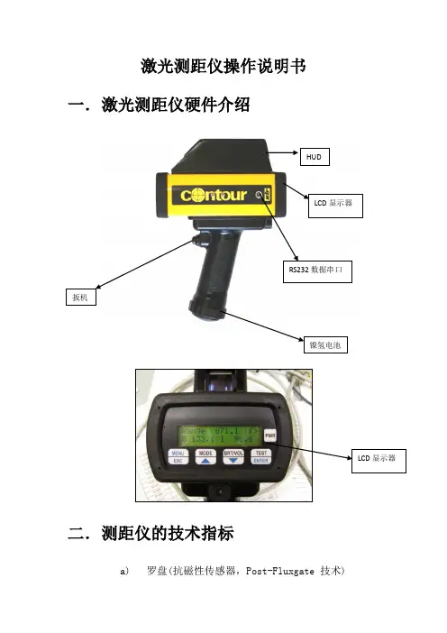
激光测距仪操作说明书一.激光测距仪硬件介绍HUDLCD显示器RS232数据串口扳机LCD显示器二.测距仪的技术指标a)罗盘(抗磁性传感器,Post-Fluxgate 技术)i."0.5 º 精确度b)磁倾仪i."0.1 º 倾斜精度ii."40 º 倾斜范围c)测距i.精度–测85米外的白目标精度为0.1米ii.最大距离–1850米(反射目标)iii.最小距离–3米iv.高压输电线175米v.杆状标志400米vi.树(无叶)400米vii.建筑物,树(有叶)800米三.激光测距仪的基本操作3.1 如何校对激光测距仪●开启电源●按“MENU” 健●用>?键来进行功能选择●选择“COMP” 并按下“Enter” 键●选择“CAL” 并按下“Enter” 键●LCD显示窗显示“Initializing Please Wait!” &“Rotate Unit for Calibration” 信息●以射击的姿势扣住扳机. LCD显示窗显示“Data PointCount” 信息●慢慢转动Contour枪1-2圈. 每圈用45-60秒钟完成●慢慢转动Contour枪1-2圈. 每圈用45-60秒钟完成●在转动中,慢慢地从上到下,从左到右移动(±40º的范围)●虽着 Contour 的移动, 你将看到数据点(Data PointCount) 在增加。
当其值增加到275时,罗盘校对操作就完成了。
松开板机,系统恢复原来的设置●每次系统上电都必须要重复以上操做3.2 开机自检自检信息:仪器开机后将进行自检,自检信息将显示在LCD 显示屏上:Selft TestControur XLRic当自检信息结束后回到以前的测量界面时,说明自检成功,否则会出现以下错误信息:End Of Self Test*** Fall3.3 标准测量模式下的测量标准模式是仪器在开机后默认的模式,在这种模式下,仪器将显示所测目标的距离、方位和倾斜值。
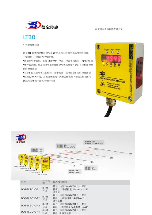
南京德宝传感科技有限公司LT30中程距离传感器德宝TLS激光测距传感器可在30米范围内检测垂直或倾斜的目标,不受颜色、材料或光泽度影响。
•越限继电器输出,支持NPN/PNP;电压、电流模拟输出;RS485输出•优异的范围、重复精度和准确度组合可实现高度可靠的目标检测和精确的距离测量•五个8段显示屏和按钮编程,易于安装、故障排除和实时距离测量•耐用的IP67外壳、高度抗环境光干扰和各种温度下稳定的性能在有挑战性的环境中提供可靠的性能Q4XTILAF300-Q8详细技术参数型号可调范围输入/输出参数DOB-TLS-01C-A1 0-1M可调输入:电压10-30VDC(±10%)输出:一路模拟量(0-10V),一路开关量DOB-TLS-01C-A2 0-1M可调输入:电压10-30VDC(±10%)输出:一路模拟量(4-20MA ),一路开关量DOB-TLS-01C-A3 0-1M可调输入:电压10-30VDC(±10%)输出:一路模拟量(4-20MA )+485DOB-TLS-01C-A4 0-1M可调输入:电压10-30VDC(±10%)输出:2路开关量南京德宝传感科技有限公司供电电压U V DC 10V (30V)残余纹波≤ 5 V功耗≤ 2.1W 4)初始化时间≤250ms预热时间≤10s外壳材料铝合金(AL)有机玻璃(PMMA)连接类型M12防水接头,引线显示器5位数码管, 5 x LED 重量360g外壳防护等级IP65防护等级III。
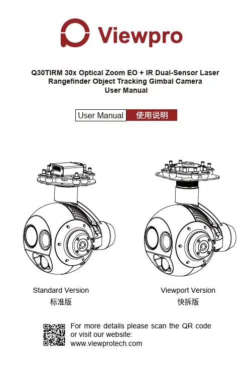
Q30TIRM 30x Optical Zoom EO + IR Dual-Sensor LaserRangefinder Object Tracking Gimbal CameraUser ManualStandard Version标准版快拆版Viewport VersionFor more details please scan the QR code or visit our website:Disclaimer and WarningLegends1.1 Introduction1.Important NoteWarningQ30TIRM is a powerful 3-axis gimbal integrated with a 30x optical zoom SONY camera, a 25mm lens 640*480 IR thermal sensor and a 1.5km laser rangefinder. It supports visible optical zoom, IR thermal and visible PIP switch, IR color palette switch, photograph-ing and video, target tracking, thermal digital zoom. When the external GPS and time input, the OSD can display angle, zoom times, target GPS location, target distance measured, real-time, tracking frame, photo and video status, also can select to turn off the OSD. It features fast focus and sensitive distance measurement. The high-precision laser rangefinder can accurately resolve the GPS location and distance of the object within 1.5km. The 3 axis gimbal can achieve stabilization in yaw, roll and pitch. The integrated design of damping system and gimbal can greatly reduce mechani-cal vibration.Q30TIRM is widely used in UAV industries of public security, electric power, fire fighting, zoom aerial photography and other industrial applications.Congratulations on purchasing your new Viewpro product. Please read this entire document carefully. Failure to read or follow instruc-tions and warnings in this document may result in damage to your Viewpro product. Disassemble the gimbal camera by user is not permitted, as which may cause the camera does not work normally.Viewpro accepts no liability for damage, injury or any legal responsi-bility incurred directly or indirectly from the use of this project. The user shall observe safe and lawful practices including, but no limited to, those set forth in the manual.1.2 In the Box2.2.1 Overview3.ViewportControl Box Back Side (Standard Version)(Viewport Version)[13][14][12][11]2. Installation Instruction[1][7][8][2][3][9][10][11][6][5][4]4.2.2.1 Control Box Printing (Standard Version)[1] Control box [2] Upper damping board [3] Lower damping board [6] FHD zoom camera [7] Damping ball [8] Yaw axis motor[9] TF card slot [10] Roll axis motor [11] Pitch axis motor [12] 3-6S power interface [13] Micro HDMI interface [15] Viewport unlock button[14] Ethernet interface [4] Infrared thermal camera [5] laser rangefinderMULPlease ensure that there isn’t any obstacle while the motor rotating.Please remove the obstacle immediately if gimbal camera is blocked during rotation.Don’t put the infrared thermal camera towards the sun in case any burn to the cameraThe input voltage cannot be higher than 6S.The pin insertion interface cannot be connected with power supply.The yellow jumper cap cannot be removedFront Side2.2.2 Control Box Printing (Viewport Version)5.Left SideRight SideMUL6..57.φ3.12.4 Install Mounting Part(1) Find out the arrow on the gimbal which indicating the yaw heading of the payload (i.e. the lens direction when the camera power on), and synchronize with the direction specified by the UAV.(2) Fix one end of the copper cylinder on the screw hole of lower damping board, and use M3 screw to fasten it.(3) According to the provided screw hole dimension you can make suitable mounting holes on the UAV mounting board, and fixes the other end of the copper cylinder on the mounting board of the UAV (Viewport version is the same).Front8.2.5 Viewport Release Instruction9.2. Align the white dot (unlock icon) to the red triangle (below unlock button), push the gimbal into the Viewport completely and then rotate the gimbal camera anticlockwise.3. When you hear "click" sound (when red dot is aligned to the red triangle) means the gimbal camera and Viewport has been locked.4. To unlock the Viewport, you need to press on unlock button and rotate the gimbal camera clockwise till the white dot align to the red triangle. Then pull the gimbal out from the Viewport.2.6 Install TF CardTF (Micro SD card): Install the TF card to the card slot (Re. 2.1 Overview). Support max 128GB. Request Class 10 (10m/s) transmis-sion speed or higher and FAT32 or exFAT format.Make sure device is power off when inserting the TFcard, hot plugging is not supported.2.7 Image Output InterfaceHDMI: micro HDMI output, HD 1080P 60/50/30/25fps, 1080P 60fps as default. (Optional)Network: Ethernet output interface, support RTSP/RTMP/UDP video streaming. Default: RTSP output, IP address: RTSP: //192.168.2.119:554, output resolution: 720P (record in 1080p), frame rate: 25fps, bit rate: 2M. (Optional)SDI: SMA outer screw inner hole interface, 1080P 30fps output. (Optional)AV: no AV output3.1 PWM ControlControl the gimbal camera functions by the multiplex pulse width modulation signal outputted by PWM channel of the remote control receiver. The camera needs up to 6 control channels of PWM (to expand tracking function use up to 7 PWM channels). You can choose needed functions according to actual usage to reduce the required number of PWM channels.3.1.1 PWM Connection Diagram (Connect pitch chan-nel as example)Above output mode is optional, HDMI and SDI outputcannot coexist at the same time. Please subject toyour actual product.When using user interface software Viewlink fornetwork connection, the network of external device(computer) should be the IP address: 192.168.2.2(choose the last byte among 2~254, can not be 119same as the gimbal), subnet mask: 255.255.255.0,Default gateway: 192.168.2.1, and all firewalls of thecomputer must be closed. Then enter the IP addressof the gimbal camera, Open Video, the video stream can be outputted.MULRemote Controller Remote Controller Connection Diagram(Standard Version)Connection Diagram(Viewport Version)ReceiverReceiver3.1.2 PWM Control Operation Instruction 1) Pitch (PWM Pitch channel in to control Pitch. Joystick, rotary knob or 3-gear switch on remote control are optional. 3-gear switch as example.)2) Yaw (PWM Yaw channel in to control Yaw. Joystick, rotary knob or 3-gear switch on remote control are optional. 3-gear switch as example.)3) Mode (PWM Mode channel in to adjust speed control/one key to Home position etc functions. Rotary knob or 3-gear switch on remote control are optional. 3-gear switch as example.)Low GearPitch Up Position 1Middle Gear Pitch Stop Position 2High Gear Pitch DownPosition 3Low GearYaw Left Position 1Middle Gear Yaw Stop Position 2High Gear Yaw RightPosition 3Function of continuous switching:3.1) Operate 1 time continuously and quickly, from position 2 - 3 - 2, to Home position.3.2) Operate 2 times continuously and quickly, from position 2 - 3 - 2 - 3 - 2, the camera lens looks vertically down.3.3) Operate 3 times continuously and quickly, from position 2 - 3 - 2 - 3 - 2 - 3 - 2, to disable Follow Yaw Mode (gimbal yaw not follows by frame)3.4) Operate 4 times continuously and quickly, from position 2 - 3 - 2 - 3 - 2 - 3 - 2 - 3 - 2, to enable Follow Yaw Mode (gimbal yaw follows by frame)Position 1: Low speed mode, control pitch / yaw with this mode at lowest speedPosition 2: Middle speed mode, control pitch / yaw with this mode at middle speedPosition 3: High speed mode, control pitch / yaw with this mode at highest speed(If it is controlled by rotary knob, the speed will change according to switch position)Low Gear Position 1Middle Gear Position 2High GearPosition 34) Zoom (PWM Zoom channel in to control Zoom. Joystick, rotary knob or 3-gear switch on remote control are optional. 3-gear switch as example.)5) Focus (PWM Focus channel is to control PIP / IR color palette switch. 3-gear switch as example.)6) Pic/Rec (PWM Pic/Rec channel in to control take picture and record. Joystick, rotary knob or 3-gear switch on remote control are optional. 3-gear switch as example.)Switch from Position 2 to 1: Picture in Picture. EO+IR , IR+EO, EO only, IR only.Switch from Position 2 to 3: IR color switching: white hot, black hot, pseudo color .Low GearZoom Out Position 1Middle Gear Stop Zoom Position 2High Gear Zoom InPosition 3Low GearPIP switch Position 1Middle Gear No control Position 2High Gear IR color palette switchPosition 3Switch from Position 2 to 1: Take a picture OSD display 'REC IMG' a second.7) Multi: IR digital zoom / tracking controlLow Gear Position 1Middle Gear Position 2High Gear Position 3Low Gear Position 1Middle Gear Position 2High Gear Position 3Switch from Position 2 to 1: IR digital zoom, 1x~4xSwitch from Position 2 to 3:Exit the tracking, display the cross cursor. Adjust the cross cursor to lock target object and start trackingSwitch from Position 3 to 2:Cancel trackingSwitch from Position 2 to 3: Start record / repeat operation to stop recordStart record, the OSD display rec hh:mm:ss.Stop record, the OSD display STBY .3.2 Serial Port / TTL ControlGimbal CameraCable PCRX (White)TXRXGND TX (Green)GND (Black)TTL communication requirements: TTL signal is 3.3V, baud rate: 115200, data bit 8, stop bit 1, no parity, HEX send and receive.Control Box Connection Diagram Standard VersionConnection Diagram Viewport VersionConnection Diagram (PC - USB to TTL Cable- Gimbal Camera as example):Diagram of USB to TTL Cable:Connect the camera to the upper computer by USB to TTL cable (Adopt connection method of TX to RX, RX to TX, GNG to GND at Dupont ends of the provided USB to TTL cable, connect to the specified TTL of the gimbal, and the USB end of the cable connect to computer).Install Viewlink control software to test the functions directly. Users may choose to develop their own software, please contact technical support for TTL control protocol file.ViewLink is a user interface developed by Viewpro for Viewpro gimbal cameras, you can download it from Viewpro website () or ask distributors for installation package.Connect serial port of gimbal to pins, DO NOT connectwith power supply.The default baud rate of serial port is 115200, whichcan be changed according to the docking equipment.3.3 S.BUS ControlControl the gimbal camera functions by one combining signals. Connect the external S.Bus to S.Bus port on the control box, and the external S.bus signal GND connect to the GND interface of the control box.Wiring Diagram (Take Futaba remote control for example):20.S.BUSRemote Control Remote Control Wiring Diagram Standard Version Wiring Diagram Viewport VersionS.Bus control mode: default S.Bus signal channel 9-15 to control gimbal camera functions (the function of channel is consistent with corresponding channel in PWM function description)Channel 9: Yaw ControlChannel 10: Pitch ControlChannel 11: Mode ControlChannel 12: Zoom ControlChannel 13: Focus ControlChannel 14: Pic/Rec ControlChannel 15: Multi BackupUser can set the channels by setting serial commandaccording to the actual requirement. The S.Bus channelposition can be arranged in any sequence withinchannel 1-15 to connect with the flight controller orremote control.TTL control and S.bus control cannot coexist at thesame time for standard version. The defualt control isTTL if no requirement. The user can set to S.bus controlif needed (please contact with our technical support forthe setting instruction.)3.4 TCP controlFor Viewpro gimbal cameras with Ethernet output, the default IP address is: 192.168.2.119, control port: 2000. You can send the corresponding protocol to realize TCP control after connecting.The TCP control protocol is [Frame header: EB + command ID: 90 + data body (serial port protocol) + Checksum (CS = body checksum, checksum is calculated as a sum of all bytes of data body modulo 256)]. Or directly use UI Viewlink to control after TCP connection.21.22.23.25.26.27.1. How to deal with whitening visible image of Q30TIRM in foggy weather?A: Enable defogging mode.2. Does Q30TIRM support taking photos during recording?A: Yes.3. How to set the storage format of Q30TIRM?A: When the IP output resolution is set to 1280*720, the storage resolution is 1920 * 1080; Storage resolution is 1280 * 720 when the IP output resolution is set to 1920*1080; The video frame rate saved in the TF card is the same with the one set during IP output. The frame rate is 25fps or 30fps for optional.4. Does Q30TIRM support simultaneous TCP control for multiple devices?A: Yes.5. How to switch the target position or the current aircraft position of OSD for Q30TIRM?A: Send the serial command for switching. After command is sent successfully, reboot gimbal to save setting.Display the target GPS position "AA 55 0F 31 FF", display the current GPS position of the aircraft "AA 55 0F 30 FF".。
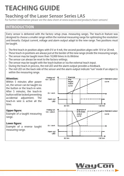
TEACHING GUIDETeaching of the Laser Sensor Series LASFor further information please see the data sheet at /products/laser-sensors/that the distance between sensor and target should be as small as possible. MR stands for the taught measurement S-TM-101618.52123.52605101520MR <4 mm MR 6 mmMR 8 mmMR 10 mm± L i n e a r i t y (μm )Measurement range (mm)1618,52123.526012345678MR <4 mmMR 6 mm MR 8 mm MR 10 mm R e s o l u t i o n (μm )Measurement range (mm)LAS-TM-10416426894120050100150200250300350400MR 2 mm MR 50 mm MR 104 mm± L i n e a r i t y (μm )Measurement range (mm)16426894120020406080100120140160MR 2 mm MR 25 mm MR 50 mm MR 75 mm MR 104 mmR e s o l u t i o n (μm )Measurement range (mm)LAS-TM-3005012520027535000.511.52MR <25 mm MR 150 mmMR 300 mm± L i n e a r i t y (m m )Measurement range (mm)5012520027535000.10.20.30.40.50.6MR <25 mm MR 75 mm MR 150 mm MR 225 mm MR 300 mmR e s o l u t i o n (m m )Measurement range (mm)LAS-TM-5005015025035045055000,511,522,533,54MR 10 mm MR 250 mmMR 500 mm± L i n e a r i t y (m m )Measurement range (mm)5015025035045055000.20.40.60.811.21.4MR 10 mm MR 250 mm MR 500 mmR e s o l u t i o n (m m )Measurement range (mm)that the distance between sensor and target should be as small as possible. MR stands for the taught measurement S-T5-403040506070010203040506070MR 2 mm MR 20 mmMR 40 mm± L i n e a r i t y (μm )Measurement range (mm)30405060700510********MR 2 mm MR 10 mm MR 20 mm MR 30 mm MR 40 mmR e s o l u t i o n (μm )Measurement range (mm)LAS-T5-100305580105130050100150200250MR 3 mm MR 50 mmMR 100 mm± L i n e a r i t y (μm )Measurement range (mm)30558010513001020304050607080MR 3 mm MR 25 mm MR 50 mm MR 75 mm MR 100 mmR e s o l u t i o n (μm )Measurement range (mm)LAS-T5-25050112.5175237.530000.20.40.60.811.2MR 5 mm MR 100 mm MR 250 mm± L i n e a r i t y (m m )Measurement range (mm)50112.5175237.530000.050.10.150.20.250.30.350.40.45MR 5 mm MR 50 mm MR 100 mm MR 175 mm MR 250 mmR e s o l u t i o n (m m )Measurement range (mm)LAS-T5-50010022535047560000.511.522.5MR 10 mm MR 250 mm MR 500 mm± L i n e a r i t y (m m )Measurement range (mm)10022535047560000.10.20.30.40.50.60.70.80.9MR 10 mm MR 100 mm MR 250 mm MR 375 mm MR 500 mmR e s o l u t i o n (m m )Measurement range (mm)LAS-T-800200400600800100000.20.40.60.811.21.41.61.822.2MR 16 mm MR 200 mmMR 400 mm MR 600 mm MR 800 mm ± L i n e a r i t y (m m )Measurement range (mm)200400600800100000.10.20.30.40.50.6MR 16 mm MR 200 mm MR 400 mm MR 600 mm MR 800 mmR e s o l u t i o n (m m )Measurement range (mm)When teaching the measurement range, it is recommended to always select the smallest possible range, because this way the resolution is increased and the linearity error decreased. Also keep in mind that the distance between sensor and target should be as small as possible. MR stands for the taught measurement range.LAS-TB-1050556030323436384042444648± L i n e a r i t y (µm )Measurement range (mm)50556010111213141516R e s o l u t i o n (µm )Measurement range (mm)LAS-TB-4060708090100405060708090100110120130MR 30 mm MR 40 mm± L i n e a r i t y (µm )Measurement range (mm)6070809010010152025303540MR 30 mm MR 40 mmR e s o l u t i o n (μm )Measurement range (mm)LAS-TB-1001001251501752000.10.150.20.250.30.350.40.450.5MR 75 mm MR 100 mm± L i n e a r i t y (m m )Measurement range (mm)1001251501752000.020.040.060.080.100.120.140.16MR 75 mm MR 100 mmR e s o l u t i o n (m m )Measurement range (mm)TEACHING BY TEACH LINELEGEND。
Quick Start GuideLaser displacement sensor that supports IO-Link communication with analog and discrete (switched) outputs.This guide is designed to help you set up and install the L-GAGE LM Analog/Discrete Laser Sensor. For complete information on programming, performance, troubleshooting, dimensions, and accessories, please refer to the Instruction Manual at . Search for p/n 205812 to view the manual. Use of this document assumes familiarity with pertinentindustry standards and practices.WARNING:•Do not use this device for personnel protection•Using this device for personnel protection could result in serious injury or death.•This device does not include the self-checking redundant circuitry necessary to allow its use inpersonnel safety applications. A device failure or malfunction can cause either an energized (on) or de-energized (off) output condition.Features and Indicators132Three LED indicators provide ongoing indication of the sensing status.1. Analog Output LED IndicatorSolid Amber = Displayed distance is within the taught analog output window Off = Displayed distance is outside the taught analog output window 2. Power LED IndicatorSolid Green = Normal operation, power On and laser OnFlashing Green (1 Hz) = Power On and laser Off (laser enable mode)3. Discrete Output LED IndicatorSolid Amber = Discrete Output is On Off = Discrete Output is OffLaser Description and Safety InformationCAUTION:•Return defective units to the manufacturer.•Use of controls or adjustments or performance of procedures other than those specified herein mayresult in hazardous radiation exposure.•Do not attempt to disassemble this sensor for repair. A defective unit must be returned to themanufacturer.Class 2 Laser Models (LM150 Models)CAUTION:•Never stare directly into the sensor lens.•Laser light can damage your eyes.•Avoid placing any mirror-like object in the beam. Never use a mirror as a retroreflective target.For Safe Laser Use - Class 2 Lasers•Do not stare at the laser.•Do not point the laser at a person’s eye.•Mount open laser beam paths either above or below eye level, where practical.•Terminate the beam emitted by the laser product at the end of its useful path.Reference IEC 60825-1:2007, Section 8.2.L-GAGE ® LM Series Laser SensorOriginal Document 205811 Rev. D27 July 2020205811Class 2 LasersClass 2 lasers are lasers that emit visible radiation in the wavelength range from 400 nm to 700 nm, where eye protection is normally afforded by aversion responses, including the blink reflex. This reaction may be expected to provide adequate protection under reasonably foreseeable conditions of operation, including the use of optical instruments for intrabeam viewing.LASER LIGHTDO NOT STARE INTO BEAMCLASS 2 LASER PRODUCTAcc to IEC 60825-1:2007.λ=640-670nm; P=0.45mWPW: 45-1,750msComplies with 21 CFR 1040.10 and 1040.11Except for deviations pursuant to laser noticeNo. 50, Dated June 24, 2007.Figure 1. FDA (CDRH) warning label (Class 2)Class 2 Laser Safety NotesLow-power lasers are, by definition, incapable of causing eye injury within the duration of ablink (aversion response) of 0.25 seconds. They also must emit only visible wavelengths(400 to 700 nm). Therefore, an ocular hazard may exist only if individuals overcome theirnatural aversion to bright light and stare directly into the laser beam.Class 1 Laser Models (LM80 Models)Class 1 lasers are lasers that are safe under reasonably foreseeable conditions ofoperation, including the use of optical instruments for intrabeam viewing.Figure 2. FDA (CDRH) warning label (Class 1) Laser wavelength: 655 nm Output: < 0.33 mW Pulse Duration: 45 µs to 1750 µsInstallation InstructionsSensor InstallationNote: Handle the sensor with care during installation and operation. Sensor windows soiled by fingerprints,dust, water, oil, etc. may create stray light that may degrade the peak performance of the sensor. Blow thewindow clear using filtered, compressed air, then clean as necessary using 70% isopropyl alcohol and cottonswabs or water and a soft cloth.Install the Safety LabelThe safety label must be installed on or near the LM sensors.Note:Position the label on the cable or near the sensor in a location that has minimal chemical exposure.Figure 3. Typical installation; other mounting options are possible.1.Remove the protective cover from the adhesive on the label.2.Wrap the label around the LM cable, as shown.3.Press the two halves of the label together. - Tel: + 1 888 373 6767P/N 205811 Rev. DSensor OrientationCorrect sensor-to-object orientation is important to ensure proper sensing. See the following figures for examples of correct and incorrect sensor-to-object orientation as certain placements may pose problems for sensing distances.Figure 4. Orientation by a wall IncorrectCorrect Figure 5. Orientation in an openingIncorrectCorrectFigure 6. Orientation for a turning objectIncorrectCorrectFigure 7. Orientation for a height difference IncorrectCorrectFigure 8. Orientation for a color or luster difference Figure 9. Orientation for a highly reflective targetApplying tilt to sensor may improve performance on reflective targets. The direction and magnitude of the tilt depends on the application, but a 15° tilt is often sufficient.Mount the Device1.If a bracket is needed, mount the device onto the bracket.2.Mount the device (or the device and the bracket) to the machine or equipment at the desired location. Do not tighten themounting screws at this time.3.Check the device alignment.4.Tighten the mounting screws to secure the device (or the device and the bracket) in the aligned position.Wiring Diagrams+–* Push-Pull output. User-configurable PNP/NPN setting.*Key 1 = Brown 2 = White 3 = Blue 4 = Black 5 = Gray+–* Push-Pull output. User-configurable PNP/NPN setting.*The bare shield wire is connected internally to the sensor housing and should be connected as follows:•If the sensor housing is mounted so that it is in continuity with both the machine frame and earth ground, connect the barewire (also) to earth ground.•If the sensor housing is mounted so that it is insulated from the machine frame and you are experiencing noise, connectingthe bare wire to -V dc (together with the blue wire), may help.•If the sensor is mounted so that it is in continuity with the machine frame, but not with earth ground, do not connect thebare wire (e.g. cut off the bare wire).P/N 205811 Rev. D - Tel: + 1 888 373 67673Configuration InstructionsSensor ProgrammingProgram the sensor using the buttons on the RSD1 remote sensor display accessory, via IO-Link, or the remote input (limited programming options).If you are using the RSD1 for programming, from Run mode, use the buttons to access the Quick Menu and the Sensor Menu. See the instruction manual (p/n 205812) for more information on the options available from each menu. For TEACH options, follow the TEACH instructions in the instruction manual.In addition to programming the sensor, use the remote input to disable the buttons for security, preventing unauthorized or accidental programming changes. See the instruction manual for more information.from Run Mode> 4 sec.Access Sensor Menu Access RSD1 MenuFigure 10. Accessing the MenusRemote Display Buttons and the LMUse the RSD1 buttons Down , Up , Enter , and Escape to view or change RSD1 settings and information and to program a connected sensor.Down and Up Buttons Press Down and Up to:•Access the Quick Menu from Run mode •Navigate the menu systems •Change programming settings•Change individual digit values in distance based settings When navigating the menu systems, the menu items loop.Press Down and Up to change setting values. Press and hold the buttons to cycle through numeric values. After changing a setting value, the value slowly flashes until the change is saved using the Enter button.Enter Button Press Enter to:•Access the Sensor Menu from Run mode •Access the submenus•Move right one digit in distance based settings •Save changesIn the RSD1 Menu, a check mark in the lower right corner of the display indicates that pressing Enter accesses a submenu.Press Enter to save changes. New values flash rapidly, and the sensor returns to the parent menu. - Tel: + 1 888 373 6767P/N 205811 Rev. DEscape ButtonPress and hold Escape for 4 seconds to:•Access the RSD1 Menu while in Run modePress Escape to:•Leave the current menu and return to the parent menuImportant: Pressing Escape discards any unsaved programming changes.In the RSD1 Menu, a return arrow in the upper left corner of the display indicates that pressing Escape returns to the parent menu.Press and hold Escape for 2 seconds to return to Run mode from the RSD1 Menu.Quick MenuThe sensor includes a Quick Menu with easy access to view and change the analog and discrete output switch points.Access the Quick Menu by pressing Down or Up from Run mode. When in the Quick Menu, the current distance measurement displays on the first line and the menu name and the analog value alternate on the second line of the display. Press Enter to access the switch points.Press Down or Up to change the switch point to the desired value.Press Enter to save the new value and return to the Quick Menu.* In Setpoint mode, SPt1 Pt is replaced by SPt and SPt2 Pt is not available.In Dual mode, SPt1 is replaced by DualSPt and SPt2 Pt is not available.Sensor Menu (MENU)Access the Sensor Menu by pressing Enter from Run mode. The Sensor Menu is also accessible from the Quick Menu: navigate to MENU and press Enter. The Sensor Menu includes several submenus that provide access to view and change sensor settings and to view sensor information.P/N 205811 Rev. D - Tel: + 1 888 373 67675SensorMenu Full MapFrom Run mode, press Enter to enter the top-level menu system (A_OUT, D_OUT, INPUT, MEASURE, etc).Top Menu* Factory default setting - Tel: + 1 888 373 6767P/N 205811 Rev. DSpecificationsSupply Voltage (Vcc)10 V dc to 30 V dcUse only with a suitable Class 2 power supply (North America) Power and Current Consumption, exclusive of loadNormal Run Mode: 1.5 W, Current consumption < 62 mA at 24 V dc Supply Protection CircuitryProtected against reverse polarity and transient overvoltages Ambient Light Immunity10,000 luxConstructionHousing: stainless steelWindow: acrylic Sensing BeamVisible red, 655 nmSensing RangeLM80: 40 to 80 mmLM150: 50 mm to 150 mmDelay at Power Up2.1 sMeasurement/Output Rate0.25 ms to 4 ms; user selectable from the Speed menu Output ConfigurationAnalog output: 4 to 20 mA (LM...I Models) or 0 to 10 V DC (LM...U Models)Discrete output: Push/Pull, IO-LinkOutput RatingsDiscrete Output: 50 mA maximum (protected against continuous overload and short circuit)Output saturation voltage (PNP): < 3 V at 50 mAOutput saturation voltage (NPN): < 2.5 V at 50 mAAnalog current output (LM...I Models): 500 Ω maximumAnalog voltage output (LM...U Models): 1000 Ω minimum Maximum Torque1.5 N·mRemote InputAllowable Input Voltage Range: 0 to VccActive Low (internal weak pullup—sinking current):High State: > 3.6 VLow State: < 2.4 VActive High (internal weak pulldown—sourcing current): High State: > Vcc - 2.9 VLow State: < Vcc - 4.6 VMinimum Window Size, Analog and DiscreteLM80:Analog: 1 mmDiscrete: 0.024 mmLM150:Analog: 1 mmDiscrete: 0.1 mm Analog ResolutionLM80: 0.002 mmLM150: 0.004 mmRepeatabilityLM80: ± 0.001 mm1LM150: ± 0.002 mm 2Analog and IO-Link LinearityLM80:40–70 mm: ± 0.02 mm70–80 mm: ± 0.03 mmLM150:50–120 mm: ± 0.06 mm120–150 mm: ± 0.07 mmIO-Link Accuracy3LM80: ± 0.175 mmLM150: ± 0.2 mmTemperature Effect, TypicalLM80: ± 0.006 mm/°CLM150: ± 0.008 mm/°CResponse TimeTotal response speed varies from 0.5 ms to 2048 ms, depending on base measurement rate and averaging settings.See Instruction Manual for more information.Minimum Object SeparationLM80:Uniform targets (6% to 90% reflectivity) 40–70 mm: 0.04 mmUniform targets (6% to 90% reflectivity) 70–80 mm: 0.06 mmNon-uniform targets (6% to 90% reflectivity): 0.4 mmLM150:Uniform targets (6% to 90% reflectivity) 50–120 mm: 0.120 mmUniform targets (6% to 90% reflectivity) 120–150 mm: 0.140 mm Non-uniform targets (6% to 90% reflectivity): 0.8 mm Environmental RatingIEC IP67Operating Conditions–10 °C to +55 °C (+14 °F to +131 °F)90% at +55 °C maximum relative humidity (non-condensing) Storage Temperature–35 °C to 60 °C (–31°F to 140 °F)Boresighting± 0.70 mm at 40 mm± 0.87 mm at 50 mm± 1.40 mm at 80 mm± 2.62 mm at 150 mmVibration/Mechanical ShockMeets IEC 60947-5-2 (10 to 60 Hz max., double amplitude 0.06 in, max acceleration 10G. 30G 11 ms duration, half sine wave) Application NoteFor optimum performance, allow 10 minutes for the sensor to warm upCertificationsUL Type 1with 128× averaging. With 1× averaging, repeatability of ± 0.004 mm from 40 to 80 mm.with 128× averaging. With 1× averaging, repeatability of ± 0.005 mm from 50 to 120 mm and ± 0.010 mm from 120 to 150 mm.3The accuracy specification refers to the possible absolute offset when installing a sensor without taking any reference measurement.Linearity is the more relevant specification for most applications.P/N 205811 Rev. D - Tel: + 1 888 373 67677Typical Beam Spot Size4Required Overcurrent ProtectionWARNING: Electrical connections mustbe made by qualified personnel inaccordance with local and nationalelectrical codes and regulations.Overcurrent protection is required to be provided by endproduct application per the supplied table.Overcurrent protection may be provided with external fusing orvia Current Limiting, Class 2 Power Supply.Supply wiring leads < 24 AWG shall not be spliced.For additional product support, go to.FCC Part 15 and CAN ICES-3 (B)/NMB-3(B)This device complies with part 15 of the FCC Rules and CAN ICES-3 (B)/NMB-3(B). Operation is subject to the following two conditions:1.This device may not cause harmful interference, and2.This device must accept any interference received, including interference that may cause undesired operation.This equipment has been tested and found to comply with the limits for a Class B digital device, pursuant to part 15 of the FCC Rules and CAN ICES-3 (B)/NMB-3(B). These limits are designed to provide reasonable protection against harmful interference in a residential installation. This equipment generates, uses and can radiate radio frequency energy and, if not installed and used in accordance with the instructions, may cause harmful interference to radio communications. However, there is no guarantee that interference will not occur in a particular installation. If this equipment does cause harmful interference to radio or television reception, which can be determined by turning the equipment off and on, the user is encouraged to try to correct the interference by one or more of the following measures:•Reorient or relocate the receiving antenna.•Increase the separation between the equipment and receiver.•Connect the equipment into an outlet on a circuit different from that to which the receiver is connected.•Consult the manufacturer.Banner Engineering Corp. Limited WarrantyBanner Engineering Corp. warrants its products to be free from defects in material and workmanship for one year following the date of shipment. Banner Engineering Corp. will repair or replace, free of charge, any product of its manufacture which, at the time it is returned to the factory, is found to have been defective during the warranty period. This warranty does not cover damage or liability for misuse, abuse, or the improper application or installation of the Banner product.THIS LIMITED WARRANTY IS EXCLUSIVE AND IN LIEU OF ALL OTHER WARRANTIES WHETHER EXPRESS OR IMPLIED (INCLUDING, WITHOUT LIMITATION, ANY WARRANTY OF MERCHANTABILITY OR FITNESS FOR A PARTICULAR PURPOSE), AND WHETHER ARISING UNDER COURSE OF PERFORMANCE, COURSE OF DEALING OR TRADE USAGE. This Warranty is exclusive and limited to repair or, at the discretion of Banner Engineering Corp., replacement. IN NO EVENT SHALL BANNER ENGINEERING CORP. BE LIABLE TO BUYER OR ANY OTHER PERSON OR ENTITY FOR ANY EXTRA COSTS, EXPENSES, LOSSES, LOSS OF PROFITS, OR ANY INCIDENTAL, CONSEQUENTIAL OR SPECIAL DAMAGES RESULTING FROM ANY PRODUCT DEFECT OR FROM THE USE OR INABILITY TO USE THE PRODUCT, WHETHER ARISING IN CONTRACT OR WARRANTY, STATUTE, TORT, STRICT LIABILITY, NEGLIGENCE, OR OTHERWISE.Banner Engineering Corp. reserves the right to change, modify or improve the design of the product without assuming any obligations or liabilities relating to any product previously manufactured by Banner Engineering Corp. Any misuse, abuse, or improper application or installation of this product or use of the product for personal protection applications when the product is identified as not intended for such purposes will void the product warranty. Any modifications to this product without prior express approval by Banner Engineering Corp will void the product warranties. All specifications published in this document are subject to change; Banner reserves the right to modify product specifications or update documentation at any time. Specifications and product information in English supersede that which is provided in any other language. For the most recent version of any documentation, refer to: .For patent information, see /patents.© Banner Engineering Corp. All rights reserved。
光透过型激光传感器IG 系列操作手册在使用 IG 系列 CCD 光透过型激光传感器之前,请仔细阅读本操作手册。
阅读之后,请妥善保管本手册,以便随时查阅。
IG系列的安全信息⏹一般注意事项•在启动时和操作期间,请务必监视本产品的功能与性能,并确认是否正常工作。
•建议您采取有效的安全措施,以避免万一发生问题时造成任何损坏。
•如果按照规格中未描述的任何方式改装或使用产品,则产品的功能与性能不予保证。
•请勿将本产品用于保护人体。
•请勿使本设备经受剧烈的温度变化,否则可能会发生产品故障。
*此分类基于 IEC60825-1 标准,该标准符合 FDA 的 Laser Notice No. 50(50 号激光通知)(CDRH)。
⏹激光发射停止输入激活激光发射停止输入之后,可以通过将外部输入设为 ON(2 ms 或更长时间)来停止激光发射。
外部输入为 ON 时,激光发射将一直处于停止状态。
外部输入设为 OFF 时,激光将在 2 ms 内发射出来。
有关激光发射停止输入期间不连续输出或模拟输出条件的详细信息,请参照“用户手册”的“11. 外部输入”。
异常情况使用注意事项⏹安装环境为了确保安全使用本产品,请勿将本产品安装在以下位置。
•湿度高、多尘以及通风不良的位置。
•装置会受到阳光直射的高温位置。
•存在腐蚀性气体或易燃气体的位置。
•本装置可能会直接受到振动或冲击的位置。
•水、油或化学品可能会溅到本装置上的位置。
•容易产生静电的位置。
⏹脏污的影响•灰尘、水、油等可能会导致发生测量误差。
•使用吹气装置除去粘在发射器与接收器上的脏污;对于严重的脏污,请使用蘸有酒精的软布进行擦拭。
如果发射器与接收器有划痕,则可能会发生测量误差。
•使用吹气装置除去附着在目标上的脏污,或是将脏污擦拭掉。
•如果脏污在测量范围内漂浮,请采取充分的措施,如安装防尘盖或是进行吹气。
⏹抗噪防护将本装置安装在噪声源(如发电机或高压线)附近时,可能会发生操作误差或产品故障。

激光测距传感使用手册前言尊敬的客户:衷心的感谢您选择了深圳市南方测控技术有限公司的激光测距传感器!为了让您更好的使用本激光测距传感器与防止意外事故的发生,请您在使用本激光测距传感器前仔细的阅读本说明书。
本说明书的版权归属深圳市南方测控技术有限公司所有,如在不影响本激光测距传感器整体性能的前提下所作的修改或更新,恕不另行通知。
激光测距传感器系统说明术语解释➢激光测距:利用激光对目标的距离进行准确测定。
激光测距一般采用两种方式来测量距离:脉冲法和相位法。
➢脉冲激光测距:基于激光脉冲反射时差法原理,测距仪器发射出的激光经被测量目标反射后,激光束被测距仪器接收,测距仪器记录激光往返的时间。
光速和往返时间的乘积的一半,就是测距仪器和被测量物体之间的距离。
➢激光测距传感器:为工业测量之产品,采用工业标准设计、生产和检测,可在线24小时连续实施测量,有的可以多台组网测试。
➢激光安全等级:国际上对激光有统一的分类,激光器分为四类(Class1、Class2、Class3、Class4)。
Class1激光器对人是安全的,Class2激光器对人有较轻的伤害,Class3以上的激光器对人有严重伤害,使用时需特别注意,避免对人眼直射。
➢Class2激光器:指激光器的出口光功率小于1mw,一般认为对人的眼睛是安全的,正常暴露在这种激光器的光束下不会对眼睛的视网膜造成永久性的伤害。
尽管此种激光器是安全的,但也不能长时间的直视激光光束。
如偶尔照射到人眼还不至于引起伤害,但连续观察激光束时能损伤眼睛。
此是对第二级激光器的最重要控制措施。
➢系统概述LPS系列激光测距传感器是一种功能强大的测量精确、无接触式的工业用距离测量设备,它可广泛地被集成用于各种工业用途的控制和监测系统上。
使用图例如下:LPS系列激光测距传感器是一款使用方便的工业应用激光测距仪表,特别为交通、炼钢、仓储、建筑、码头等需要自动进行距离和位置控制的应用而设计研发,具有很高地实用性。

激光位移传感器操作手册V2.0目录第1章:产品概要......................................................................... 1-11.1 包装内容 ......................................................................................... 1-11.2 各部件名称及功能........................................................................... 1-21.3 安装................................................................................................. 1-3 第2章:设定与测量 ..................................................................... 2-1 第3章:软件操作......................................................................... 3-13.1 通信设置 ......................................................................................... 3-13.2 位置读取与归零设定 ....................................................................... 3-2 第4章:通讯指令......................................................................... 4-14.1 通讯参数列表 .................................................................................. 4-14.2 通讯协议 ......................................................................................... 4-4 第5章:产品规格......................................................................... 5-1 第6章:安全注意事项.................................................................. 6-1 第7章:保固 ................................................................................ 7-1版本更新历程激光位移计操作手册V2.0版本更新历程版本更新日期V1.0 第一版发行2018/09/03V2.0 新增「反应速度设定」与「中值滤波器设定」功能说明与通讯地址设定方式。
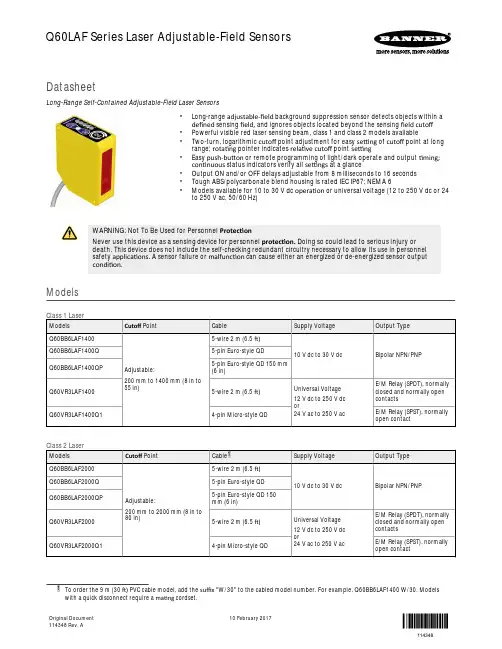
DatasheetLong-Range Self-Contained Adjustable-Field Laser Sensors•Long-range adjustable-field background suppression sensor detects objects within a defined sensing field, and ignores objects located beyond the sensing field cutoff •Powerful visible red laser sensing beam, class 1 and class 2 models available•Two-turn, logarithmic cutoff point adjustment for easy setting of cutoff point at long range; rotating pointer indicates relative cutoff point setting•Easy push-button or remote programming of light/dark operate and output timing;continuous status indicators verify all settings at a glance•Output ON and/or OFF delays adjustable from 8 milliseconds to 16 seconds •Tough ABS/polycarbonate blend housing is rated IEC IP67; NEMA 6•Models available for 10 to 30 V dc operation or universal voltage (12 to 250 V dc or 24to 250 V ac, 50/60 Hz)WARNING: Not To Be Used for Personnel ProtectionNever use this device as a sensing device for personnel protection. Doing so could lead to serious injury or death. This device does not include the self-checking redundant circuitry necessary to allow its use in personnel safety applications. A sensor failure or malfunction can cause either an energized or de-energized sensor output condition.Modelssuffix "W/30" to the cabled model number. For example, Q60BB6LAF1400 W/30. Models with a quick disconnect require a mating cordset.Q60LAF Series Laser Adjustable-Field SensorsOriginal Document 114348 Rev. A10 February 2017114348OverviewThe Q60LAF sensor is a full-featured adjustable-field sensor. These adjustable-field sensors are able to detect objects of relatively low reflectivity, while ignoring other objects in the background (beyond the cutoff point). The cutoff distance is mechanically adjustable,using the 2-turn adjustment screw on the top of the sensor. A rotating pointer indicates the relative cutoff position. The indicator moves clockwise to show increasing distance.The collimated laser emitter produces a small, bright spot, allowing easy alignment and precision sensing of relatively small objects at long range.Two push buttons (ON Delay and OFF Delay) are used to set the output delay options, to toggle between light and dark operate modes and to lock out the push buttons for security purposes. These functions also may be accomplished using the remote wire (available on some models).Seven LED indicators show, during RUN mode, the sensor configuration and operating status. During Delay Configuration, 5 of the LEDs combine to form a single light bar that indicates relative ON or OFF delaytime.Note: When an object approaches from the side, the most reliable sensing usually occurs when the line of approachis parallel to the sensing axis.Note: Sensing at closer than the minimum specified range is not guaranteed.Features and IndicatorsNote: Outputs are active during on/off timing selection mode.ON DelaySteady Green: Run mode, ON delay is activeFlashing Green: ON Delay Selection mode is active OFF DelaySteady Green: Run mode, OFF delay is activeFlashing Green: OFF Delay Selection mode is active 5-Segment Light BarIndicates relative delay time during ON or OFF Delay Selection modes Output IndicatorSteady Amber: Outputs are conductingSteady Green: During ON/OFF Delay Selection modes Dark Operate IndicatorSteady Green: Dark Operate is selected Lockout IndicatorSteady Green: Buttons are locked out Light Operate IndicatorSteady Green: Light Operate is selected Signal IndicatorSteady Green: Sensor is receiving signalFlashing Green: Marginal signal (1.0 to 2.25 excess gain)ON/OFF Delay Push Buttons and IndicatorsCutoff Adjustment ScrewLight Sensed Indicator Light Operate Selected Push Button Lockout Indicator Dark Operate Selected Output Conducting (Bi-color Amber/Green)The indicators, above right, also function as a 5-segment light gar during delay selection modesAdjustable-Field Sensing—Theory of OperationThe Q60LAF compares the reflections of its emitted light beam (E) from an object back to the sensor’s two differently-aimed detectors R1 and R2 (see Figure 1 on page 3). If the near detector (R1) light signal is stronger than the far detector (R2) light signal (see object A, closer than the cutoff distance), the sensor responds to the object. If the far detector (R2) light signal is stronger than the near detector (R1) light signal (see object B, object beyond the cutoff distance), the sensor ignores the object.The cutoff distance for these sensors is adjustable. Objects lying beyond the cutoff distance are ignored, even if they are highly reflective. However, it is possible to falsely detect a background object, under certain conditions (see Background Reflectivity and Placement on page 4). - Tel: +1-763-544-3164P/N 114348 Rev. ACutoff DistanceNear Detector Far Detector Receiver Elements EmitterSensing AxisFigure 2. Sensing AxisIn the drawings and information provided in this document, the letters E, R1, and R2 identify how the sensor’s three optical elements (Emitter “E”, Near Detector “R1”, and Far Detector “R2”) line up across the face of the sensor. The location of these elements defines the sensing axis (see Figure 2 on page 3). The sensing axis becomes important in certain situations, such as those illustrated in Figure 7on page 5 and Figure 8 on page 5.InstallationWiring DiagramsQ60BB6xx(Q)Cabled and QD Models, 10 to 30 V dc+–Q60VR3xxCabled Model, 24 to 250 V ac (50/60Hz) or 12 to 250 VdcN.C.C N.O.Key1 = Brown2 = White3 = Blue4 = Black5 = GrayQ60VR3xxQ1QD Model, 24 to 250 V ac (50/60Hz) or 12 to 250 V dc*NOTE: Connection of dc power is without regard to polarity.Key1 = Red/Black2 = Red/White3 = Red4 = GreenSet the Cutoff DistanceThe cutoff distance for Q60LAF sensors can be adjusted between 200 mm and 1400 mm (8 in to 55 in) for Class 1 laser models, and between 200 mm and 2000 mm (8 in to 80 in) for Class 2 laser models.P/N 114348 Rev. A - Tel: +1-763-544-31643To maximize contrast, position the lightest possible background to be used, at the closest position it will come to the sensor during ing a small screwdriver in the adjustment screw, adjust the cutoff distance until the threshold is reached and the green Light Sensed indicator changes state. If the indicator never turns ON, the background is beyond the maximum sensing cutoff and will be ignored.Note the position of the rotating cutoff position indicator at this position. Then repeat the procedure, using the darkest target, placed in its most distant position for sensing. Adjust the cutoff so that the indicator is midway between the twopositions.Target BackgroundCutoffDistanceFigure 3. Set the cutoff distance approximately midway between thefarthest target and the closest backgroundI n c r e a s Farthest Target Object Closest BackgroundFigure 4. Setting the cutoff distanceNote: Setting the cutoff distance adjustment screw to its maximum clockwise position places the receiver lens directly in front of the receiver elements and results in the Q60 performing as a long-range diffuse sensor.Sensing ReliabilityFor highest sensitivity, the sensor-to-object distance should be such that the object will be sensed at or near the point of maximum excess gain. The excess gain curves show excess gain versus sensing distance for 200 mm, 1200 mm, and 2 m cutoffs. Maximum excess gain for a 200 mm cutoff occurs at a lens-to-object distance of about 150 mm, and for a 2 m cutoff, at about 500 mm. The background must be placed beyond the cutoff distance. Following these two guidelines makes it possible to detect objects of low reflectivity, even against close-in reflective backgrounds.Background Reflectivity and PlacementAvoid mirror-like backgrounds that produce specular reflections. A false sensor response occurs if a background surface reflects the sensor's light more to the near detector (R1) than to the far detector (R2). The result is a false ON condition (Figure 5 on page 4).Correct this problem by using a diffusely reflective (matte) background, or angling either the sensor or the background (in any plane) so the background does not reflect light back to the sensor (Figure 6 on page 4). Position the background as far beyond the cutoff distance as possible.An object beyond the cutoff distance, either stationary (and when positioned as shown in Figure 7 on page 5), or moving past theface of the sensor in a direction perpendicular to the sensing axis, may cause unwanted triggering of the sensor if more light is reflected to the near detector than to the far detector. Correct the problem by rotating the sensor 90° (Figure 8 on page 5). The object thenreflects the R1 and R2 fields equally, resulting in no false triggering. A better solution, if possible, may be to reposition the object or the sensor.R2 = Far Detector Figure 5. ReflectiveBackground - Problem R2 = Far DetectorFigure 6. Reflective Background - Solution - Tel: +1-763-544-3164P/N 114348 Rev. AA reflective background object in this position or moving across the sensor facein this axis and direction may cause a false sensor response.Figure 7. Object Beyond Cutoff - ProblemA reflective background object in this position or moving across the sensor facein this axis is ignored.Figure 8. Object Beyond Cutoff -SolutionColor SensitivityThe effects of object reflectivity on cutoff distance, though small, may be important for some applications. It is expected that at any given cutoff setting, the actual cutoff distance for lower reflectance targets is slightly shorter than for higher reflectance targets. This behavior is known as color sensitivity.These excess gain curves were generated using a white test card of 90% reflectance. Objects with reflectivity of less than 90% reflect less light back to the sensor, and thus require proportionately more excess gain in order to be sensed with the same reliability as more reflective objects. When sensing an object of very low reflectivity, it may be especially important to sense it at or near the distance of maximum excess gain.The percentage of deviation indicates a change in the cutoff point for either 18% gray or 6% black targets, relative to the cutoff point set for a 90% reflective white test card.For example, the cutoff point decreases 10% for a 6% reflectance black target when the cutoff point is adjusted for 1700 mm (67 in) using a 90% reflectance white test card. In other words, the cutoff point for the black target is 1530 mm (60 in) for this setting.-1-2-3-4-5-6-7-8-9-10-12200400600800100012001400160018002000Cutoff Setting (90% White Card)PercentDeviationCutoff Point DeviationFigure 9. Cutoff Point Deviation200400600800100012001400160018002000Cutoff Distance (mm) with 90% White CardMinimumRange(mm)Minimum Range vs. Cutoff Setting**NOTE: Minimum range is independent of target reflectivityFigure 10. Q60 Minium Range Versus Cutoff Setting6.04.02.0200400600800100012001400160018002000Cutoff Setting (mm) with 90% White CardHysteresis(%ofCutoff)HysteresisFigure 11. HysteresisClass 2 Laser 18% Gray Card6% Black CardClass 1 Laser 18% Gray Card6% Black CardP/N 114348 Rev. A - Tel: +1-763-544-31645Configuring a SensorSet the Output DelayThe output of the Q60LAF sensor may be delayed between 0.008 and 16 seconds, in any of 72 increments. Delay is indicated on the 5-segment light bar using single LED segments or combinations of them,in varying stages of intensity.To set a delay, single-click the appropriate button or pulse the remotewire to enable the process (as described in the following procedures).Then use the + or – button or the appropriate remote wire pulse procedure to increase or decrease the delay (single-click adjusts the delay by one step at a time, and holding the button in provides a rapid increase/decrease).Major increments, displayed by a single full-intensity LED, are shown:Increase or Decrease the ON DelayT = 40 – 800 msPress and Hold > 800 ms unless otherwise noted Increase or Decrease the OFF DelayT = 40 – 800 msPress and Hold > 800 ms unless otherwise noted - Tel: +1-763-544-3164P/N 114348 Rev. ASelect Light Operate or Dark OperateSelect Light Operate or Dark Operate mode using the two push buttons or a triple-pulse of the remote line to toggle between the selections.Lock the Push ButtonsFor security, the push buttons can be locked out using either the remote line or the push buttons themselves.Enable or Disable the LaserThe laser is disabled after remote line is held low for 800 ms and will remain disabled until remote line is released.Note: 500 ms maximum delay after laser is enabled; outputs will default to “No Light” state.P/N 114348 Rev. A - Tel: +1-763-544-31647Laser Description and SafetyInformationCAUTION: Do Not Disassemble for RepairThis device contains no user-serviceable components. Do notattempt to disassemble for repair. Use of controls or adjustments or performance of procedures other than those specified herein may result in hazardous radiation exposure. A defective unit must be returned to the manufacturer.Figure 12. Laser Aperture LocationClass 1 LasersClass 1 lasers are lasers that are safe under reasonably foreseeable conditions of operation,including the use of optical instruments for intrabeam viewing.Reference IEC 60825-1:2001, Section 8.2.Class 2 LasersClass 2 lasers are lasers that emit visible radiation in the wavelength range from 400 nm to 700 nm, where eye protection is normally afforded by aversion responses, including the blink reflex. This reaction may be expected to provide adequate protection underreasonably foreseeable conditions of operation, including the use of optical instruments for intrabeam viewing.Reference IEC 60825-1:2001, Section 8.2.Class 2 Laser Safety NotesLow-power lasers are, by definition, incapable of causing eye injury within the duration of a blink (aversion response) of 0.25 seconds. They also must emit only visible wavelengths (400to 700 nm). Therefore, an ocular hazard may exist only if individuals overcome their natural aversion to bright light and stare directly into the laser beam.For Safe Laser Use (Class 1 or Class 2):•Do not stare at the laser.•Do not point the laser at a person’s eye.•Mount open laser beam paths either above or below eye level, where practical.•Terminate the beam emitted by the laser product at the end of its useful path. - Tel: +1-763-544-3164P/N 114348 Rev. ASpecificationsSupply Voltage and CurrentQ60BB6LAF models: 10 to 30 V dc (10% maximum ripple) at less than 50 mA exclusive of loadQ60VR3LAF Universal models: 12 to 250 V dc or 24 to 250 V ac, 50/60 Hz Input power: 1.5 W maximum Supply Protection CircuitryProtected against reverse polarity and transient voltages The dc wiring for model Q60VR3 is without regard to polarityOutput ConfigurationQ60BB6LAF models: Bipolar; one NPN (current sinking) and one PNP (current sourcing) open-collector transistorQ60VR3LAF cabled model: E/M Relay (SPDT), normally closed and normally open contactsQ60VR3LAFQ1 (QD) model: E/M Relay (SPST), normally open contact Output Rating—Q60BB6LAF models150 mA maximum each output @ 25 °C Off-state leakage current: < 5 μA @ 30 V dcOutput saturation NPN: < 200 mV @ 10 mA and < 1 V @150 mA Output saturation PNP: < 1 V at 10 mA; < 1.5 V at 150 mAOutput Rating—Q60VR3LAF Universal modelsMinimum voltage and current: 5 V dc, 10 mA Mechanical life of relay: 50,000,000 operationsElectrical life of relay at full resistive load: 100,000 operationsMaximum switching power (resistive load):Cabled models: 1250 VA, 150 WQD models: 750 VA, 90 WMaximum switching voltage (resistive load):Cabled models: 250 V ac, 125 V dcQD models: 250 V ac, 125 V dcMaximum switching current (resistive load):Cabled models: 5 A @ 250 V ac, 5 A @ 30 V dc derated to 200 mA @ 125 V dc QD models: 3 A @ 250 V ac, 3 A @ 30 V dc derated to 200 mA @ 125 V dc Output Protection CircuitryQ60BB6LAF models: Protected against continuous overload or short circuit ofoutputsAll models: Protected against false pulse on power-upNote: 1 second maximum delay at power up(outputs do not conduct during this time)Output Response TimeQ60BB6LAF models: 2 milliseconds ON and OFFQ60VR3LAF Universal models: 15 milliseconds ON and OFF Repeatability500 microseconds Sensing HysteresisSee Figure 11 on page 5Laser CharacteristicsSpot Size: approximately 4 × 2 mm throughout range (collimated beam)Angle of Divergence:5 milliradiansNote: Contact Banner Engineering for a custom laser spot size.AdjustmentsSlotted, geared, 2-turn, cutoff range adjustment screw (mechanical stops on both ends of travel)2 momentary push buttons: ON Delay (+) and OFF Delay (–); DC models also have a remote program wireON Delay select: 8 ms to 16 seconds OFF Delay select: 8 ms to 16 seconds LO/DO selectPush button lockout for security Laser Enable/Disable (remote wire only)ConstructionHousing: ABS polycarbonate blend Lens: Acrylic Environmental RatingIEC IP67; NEMA 6ConnectionsQ60BB6LAF models: 2 m (6.5 ft) or 9 m (30 ft) attached cable, 5-pin Euro-style integral QD, or 5-pin Euro-style 150 mm (6 in) QDQ60VR3LAF Universal models: 2 m (6.5 ft) or 9 m (30 ft) attached cable, or 5-pin Micro-style 150 mm (6 in) QDOperating Conditions Temperature:Q60BB6LAF models: −10 °C to +50 °C (+14 °F to +122 °F)Q60VR3LAF Universal models: −10 °C to +45 °C (+14 °F to +113 °F)90% at +50 °C maximum relative humidity (non-condensing)Required OvercurrentProtectionWARNING: Electrical connections must be made by qualified personnel in accordance with local and national electrical codes and regulations.Overcurrent protection is required to be provided by end product application per the supplied table.Overcurrent protection may be provided with external fusing or via Current Limiting, Class 2 Power Supply.Supply wiring leads < 24 AWG shall not be spliced.For additional product support, go to .CertificationsP/N 114348 Rev. A - Tel: +1-763-544-31649Dimensions60.0 mm(2.36")2x ø4.2 mmPerformance CurvesPerformance is based on a 90% reflectance white test card.Class 1 Laser Models—Excess Gain at 200 mm and 1200 mmCutoff110100100 mm(3.96")1000 mm(39.6")10000 mm(396")10 mm(0.396")EXCESSGAINDISTANCE1000Class 2 Laser Models—Excess Gain at 1200mm and 2000 mmCutoff110100EXCESSGAINDISTANCE1000(3.96")(39.6")(396")(0.396") - Tel: +1-763-544-3164P/N 114348 Rev. AAccessoriesCordsetsBracketsSMBQ60•Right-angle bracket•14-ga., 304 Stainless SteelP/N 114348 Rev. A - Tel: +1-763-544-316411Banner Engineering Corp. Limited WarrantyBanner Engineering Corp. warrants its products to be free from defects in material and workmanship for one year following the date of shipment. Banner Engineering Corp. will repair or replace, free of charge, any product of its manufacture which, at the time it is returned to the factory, is found to have been defective during the warranty period. This warranty does not cover damage or liability for misuse, abuse, or the improper application or installation of the Banner product.THIS LIMITED WARRANTY IS EXCLUSIVE AND IN LIEU OF ALL OTHER WARRANTIES WHETHER EXPRESS OR IMPLIED (INCLUDING, WITHOUT LIMITATION, ANY WARRANTY OF MERCHANTABILITY OR FITNESS FOR A PARTICULAR PURPOSE), AND WHETHER ARISING UNDER COURSE OF PERFORMANCE, COURSE OF DEALING OR TRADE USAGE.This Warranty is exclusive and limited to repair or, at the discretion of Banner Engineering Corp., replacement. IN NO EVENT SHALL BANNER ENGINEERING CORP. BE LIABLE TO BUYER OR ANY OTHER PERSON OR ENTITY FOR ANY EXTRA COSTS, EXPENSES, LOSSES, LOSS OF PROFITS, OR ANY INCIDENTAL, CONSEQUENTIAL OR SPECIAL DAMAGES RESULTING FROM ANY PRODUCT DEFECT OR FROM THE USE OR INABILITY TO USE THE PRODUCT, WHETHER ARISING IN CONTRACT OR WARRANTY, STATUTE, TORT, STRICT LIABILITY, NEGLIGENCE, OR OTHERWISE. Banner Engineering Corp. reserves the right to change, modify or improve the design of the product without assuming any obligations or liabilities relating to any product previously manufactured by Banner Engineering Corp. Any misuse, abuse, or improper application or installation of this product or use of the product for personal protection applications when the product is identified as not intended for such purposes will void the product warranty. Any modifications to this product without prior express approval by Banner Engineering Corp will void the product warranties. All specifications published in this document are subject to change; Banner reserves the right to modify product specifications or update documentation at any time. Specifications and product information in English supersede that which is provided in any other language. For the most recent version of any documentation, refer to:.© Banner Engineering Corp. All rights reserved。
激光测距模块说明书相位激光测距模块技术参数:测量范围:0.045-D(D是最大量程)目前模块有D=40,D=70,D=80,D=100等规格分辨率:0.01毫米(0.00001米)测量精度(标准差):±2.mm(10米内)大于10米计算公式±2+0.05*(D-10),D是距离距离单位:m激光类型:620-690nm激光等级:Ⅱ级,<1mW(二级安全)单次测量时间:0.25秒在距离m处光斑直径:6mm@10m,工作温度:-0~+40℃贮存温度:-20~+60℃重量:约60g尺寸(长×宽×厚):4.8cmX3.7cmX1.8cm供电电压:DC3v-3.3vIO电压:TTL电平兼容3v-5v电压在室内基本无需反光板,近距离内使用黑色目标也可测距,例如黑色皮质钱包表面,室外如果量程内返回无反射则请使用反光板配合.**在恶劣环境下如:阳光过于强烈,环境温度波动太大,反射面效果比较弱,系统电压多高或者过低,测量距离会比较近,结果可能会出现较大误差,此种情况建议配合使用目标反射板****模块使用禁止超出标注的电气范围,使用不符合规定的供电电压可能会损坏模块,5vIO直接相连请设置为若驱动,如果为AVR或者STC单片机,请串联1K欧姆限流电阻**通信接口:模块采用TTL串口进行数据交换,通信速率高达115k(波特率115200)只打开激光,但不测量,可用于瞄准目标(激光打开后自动超时关闭) 指令表:指令一览表指令内容应答备注启动单次测量$00022123&确认确认后跟测量数据开灯$0003260130&确认+命令重复开启连续测量$00022426&确认停止连续测量$0003260029&确认+命令重复指令确认$00023335&这是从机的确认指令最后7位是0001643没信号距离太远或激光头发射或接收头被遮挡最后7位是0001542距离太近终止连续测量$00022123&确认+命令重复可以使用单次测量指令在连续测量过成功,终止测量关闭激光$00022123&确认模块不设置休眠模式,如需关闭激光可以使用单次测量指令指令使用建议:1.激光开启,一般用于打开激光后帮助瞄准目标2.单次测量,进行一次测量,建议测距前瞄准目标3.连续测量,用于扫过一个平面或者立体面,如墙角,模块每次返回的数据均包含本次测量距离,最大值,最小值等,并在每个值前面有3位字符用来标记本条数据是否有效4.停止测量,模块未设置低功耗模式,激光打开后不自动关闭,如需要关闭激光,可以发送一次单次测距指令收发数据示例:开启激光:直接开启激光但不测距一般用于人工瞄准如将模块安装到某些设备上进行特定范围内的测距,则本指令可以省略主机发$0003260130&,模块回复确认+指令重复(中间没有+号) $00023335&$0003260130&确认指令重复单次测量模式:单次测量模式需要保证激光照射点在目标表面,如果测距之前不确定激光是否能指向目标表面请执行”开激光”指令主机发$00022123&模块回复$00023335&+测量数据,测量数据解析示例用户在读取单次测量模式的数据时,可以以$判断作为数据头,&作为数据尾(数据10字节应答+18字节测量数据)蓝色共10位(第0-9位):从机在单次测量模式下的应答绿色共7位(第20-27)第:表示距离,7位中的前两位表示整数部分,后5位表示小数部分其余字段保留以备扩展$00023335&$0006210000008916&00.08916米单次测距模式的调试截图-------------------------------------------------------------------------------------------1,模式1的错误码错误码错误原因错误响应时间$00023335&$0006210000001542&距离太近从指令发出到返回错误码大约5秒$00023335&$0006210000001643&未收到回波从指令发出到返回错误码大约5秒$00023335&$0006210000001744&反射过强从指令发出到返回错误码大约5秒$00023335&$0006210000001845&环境光过强从指令发出到返回错误码大约5秒连续测量模式连续测量模式下主机发送一个连续测距指令模块可以执行101(501次连续测量),模块每次返回的数据均包含本次测量距离,最大值,最小值等,并在每个值前面有3位字符用来标记本条数据是否有效,如果测距中出现错误(遮挡到激光发射口,透镜,或者距离太近)会输出错误码,并将测量计数置为9999,并终止本次连续测距,模块在连续测距模式下,每5次测量会关闭激光并重新打开一次,此模式一般用于慢速扫过一个平面或者立体面,如墙角,从而得到最大值和最小值,也可用于实时测距,一次触发百次测量减轻cpu 负担,并提高测量速度连续测量模式的数据解析测量数据长度为38字节蓝色(第1-6位)共6位:保留以备未来扩展红色(第7-10位)共4位:测量次数计数,最后一次测量或者出错终止测量时,测量次数计数器等于9999,则本条数据可以忽略,或重发批量测距数据,以用于不间断连续测距黑色(第11-13位)共3位:本次测量测距是否有效,后面意义相同粉红(第14-18位)共5位:本次测量距离浅蓝(第22-26位)共5位:最大值绿色(第30-37)共7位第:表示距离,7位中的前两位表示整数部分,后5位表示小数部分主机发$00022426&模块先给一个10字节应答$00023335&然后返回测距数据,实际模块返回的数据如下图,注意第一次回传测量数据会在前面带一个响应,直接丢弃即可,参考截图中的第一行数据解析示例:$001624000100004855000048550000485550&第1次04.855米最大04.855米最小04.855米(第一次测量三个值一致) $001624001000000136000048550000013627& 第10次00.136米最大04.855米最小04.855米$001624049800004830000048310000012121&第498次04.830米最大04.831米最小00.121米$001624999900004830000048310000012117&最后一次,本次数据可舍弃错误的代码示例$001624000100118297001182970011829711&第1次测量数据无效,错误代码18值模式2的错误码模式2连续测量中模块连续返回N次数据,用户可以用$作为数据头,&作为数据尾错误码原因错误响应时间说明$001624999900000015000 000000000000053&距离太从指令发出到返回错误码大约5秒如果连续测量中出现错误,测量会被停止,测量次数计数器(数据的第7到第10位)会自动设置为9999,启动新的一次测量会冲1开始计$001624999900000016000 000000000000054&未收到回波从指令发出到返回错误码大约5秒其余的情况测量数据小于00.045米都是测量错误,附录:外观尺寸和接口:端口电压功能备注VCC3-3.3V模块供电大于3.3v会烧坏GND模块电源地TXD3v-5v模块数据发送引脚可以直接5v单片机相连,推挽输出类型的io要加限流电阻,入不确定请用3.3v单片机相连RXD3v-5v模块接收数据引脚可以直接5v单片机相连,推挽输出类型的io要加限流电阻,入不确定请用3.3v单片机相连Fpc0.5mm8p翻盖式注意事项:用户禁止自行打开本模块或者焊接本模块上的任何器件,禁止将模块直视太阳将模块接触液体用酒精或者有机溶剂擦拭镜头用收或其他物体直接擦拭镜头采用额定电压以外的供电电压。
SENST系列激光测距传感器产品说明书武汉鸿诚远大科技有限公司目录一:前言二:传感器特点三:传感器技术参数四:传感器接口及接线说明五:通讯协议六:产品应用七:技术支持与售后一、前言武汉鸿诚远大科技有限公司所生产的SENST系列激光测距传感器,为新一代非接触式,高精度测距传感器。
其功能强大,结构坚固,专为工业及野外使用而设计。
适合长期在线监测使用,而且我公司免费提供在线监测系统方案,可指导施工等。
本公司产品为自行研发,可按功能为客户订做。
激光测距传感器为激光类测距产品,激光等级为二级安全,使用时请勿直射眼睛,请勿正对阳光。
本传感器标准版为只含有数据接口( RS232 )。
如有模拟量,开关量,恒温等需求,请在购买前与我们说明。
本传感器保修期为一年,终身维修。
本传感器在未做全密封的情况下,请勿在雨天暴露使用。
未要求做防腐的情况下,请勿在高腐蚀环境下使用。
本传感器以下情况不在保修范范围内:1,人为损坏或易碎签损毁。
2,非正常使用(如电源接反,电压输入超过范围,接线顺序出错等〕。
3,自然灾害损坏。
二、传感器特点·传感器可以设置的不同的地址〔最大可以设置249个不同的地址),方便单总线,多机组网。
而且通过本公司配套生产的专用接头,可无上限串连传感器。
·传感器可以为无线方式,免去您布线的麻烦。
·传感器可以加口工为全密封,能达到防水浸的防护级别。
·传感器具有模拟量反向〔可以随距离增加而减小,或随距离增加而增加)输出功能,且模拟量输出范围对应的距离可以任意调整。
非常适合于液位、料位、物位等测量。
而且模拟量输出为标准4-20MA ,可以直接接入PLC、二次仪表等设备,方便入网。
·具有开关量输出功能,而且开关输出点,开关输出状态均可通过命令进行调整。
适用于过程控制,平整度检査,厚度检测等场合。
·传感器数字接口形式有RS232,RS422,RS485可以任意切换,只需要更换一根通讯电缆即可,无需对传感器做任何改动。
L2/L2s 激光测距传感器说明书Version 1.2.2修订记录日期版本号责任人修订内容2017/06/01 1.0许工初稿2019/11/06 1.1韩工新增<快速入门>章节2021/08/081.2韩工新增<上电是否打开激光>功能,新增<上电是否打印版本信息>功能,订正错误传感器型号1、电路模块的型号:L22、带防水外壳的型号:L2s产品特点∙高精度,±(1.5mm+D*5‱),D为实测距离值∙长距离,最远80m(与反光膜配合)∙快速率,最高20Hz∙重复精度高,±1mm∙低功耗,小于0.6W∙可用于室外,不使用反光膜15m,使用反光膜80m∙宽电压输入,DC9-36V∙小体积,76x60x21mm(L2s)∙防水外壳,IP55等级,可安装在室外∙温漂小,信噪比高,受温度、表面颜色和粗糙度影响较小∙易操控,标准Modbus RTU协议重要事项∙由于L2的元器件外露,请规范操作,防止静电/瞬态电压电流/电源短路/挤压或撞击损坏器件。
a)避免裸手接触电路板,特别是光器件属于敏感器件,请务必佩戴防静电手套或手环;b)确保接线牢固,最好焊接线缆,不使用插针,避免接触不稳导致频繁上下电,瞬间的断电又上电,会冲击控制芯片和光器件损坏;∙透明液体和油,需要在液面增加反射浮标才能测量。
∙黑色物质,如原油、煤炭等黑色凝脂、固体物料,需要激光垂直正射平滑的表面,室内环境可以稳定测量12米。
∙强反射面,如镜面油漆面、不锈钢、铝板的光滑表面等,需加装漫反射的辅助材料。
近距离用白纸,远距离加3M的漫反射材料。
先在连接电脑看回光量,60#-3000#之间可以正常测距,小于60#,调整反射角度(垂直的时候最强)或者粘贴白纸等增强反射信号,大于3000#,调整反射角度(斜一定角度)或者改成磨砂面减弱信号强度。
∙避免L2的激光源和透镜喷涂绝缘漆或其它化学物品,否则激光源或透镜上的镀膜被化学物质损坏,无法发射或接收激光。
Insight-60激光测距传感器用户手册目录一前言 (3)二仪器特点 (3)三安全说明 (3)3.1 基本事项 (3)3.2 仪器的禁用范围 (3)3.3注意事项及保养 (4)3.4 激光等级 (4)四技术参数 (5)4.1 激光参数 (5)4.2 工作参数 (5)4.3 接口及指示灯 (5)4.3.1 DB9接口定义 (6)4.3.2 电源插座 (6)4.3.3 激光发射及接收口 (6)五通讯协议 (7)5.1 基本命令 (7)5.1.1 读设备地址 (7)5.1.2 读当前距离 (7)5.1.3 读最大距离 (7)5.2 扩展命令 (7)5.2.1命令格式 (7)5.2.2 开机信号 (7)5.2.3 测量 (8)5.2.4 查询设备地址 (8)5.2.5 设定设备地址 (8)5.2.6 设定偏移量 (8)5.2.7 查询偏移 (8)六、4-20mA电流环 (9)本手册里除了使用说明外,还包括了重要的安全说明。
在使用本仪器前,请务必仔细阅读本手册。
请您记住仪器型号和仪器编号,当您需要与销售商或授权的维修部联系时,会用到这些信息。
一、前言INSIGHT‐200 激光测距传感器是新一代的测距设备,功能强大、坚固耐用,专为工业测量场合设计。
该设备拥有许多卓越的性能.是一种当前最为先进的经济型在线位置检测系统,具有惊人的测试精度和极高的稳定性。
二、仪器特点✧无接触测量,保证测量人员人身安全。
✧基本不受天气条件影响,不论白天、夜晚、刮风、有雾天气都可进行测量。
✧体积小、重量轻、便于工作人员野外操作。
✧测量结果精度高,测量速度快,极大的提高了工作效率。
✧仪器测量操作简单直观,容易上手。
✧在隧道内可方便快速的测量。
✧测量结果无需换算,测量结果即为实际值。
三、安全说明3.1 基本事项本仪器为激光电气设备,非正常使用会造成危险。
仪器负责人必须保证按照《用户手册》来操作仪器,确保使用人员按照规程来使用仪器。
3.2 仪器的禁用范围✧在未阅读本说明书的情况下启动本仪器✧在仪器指定的使用范围之外使用。
TLS系列激光测距传感器TLLS-100、TLLS-200系列激光测距传感器,是新一代的工业测距控制设备,采用欧洲先进激光测距技术,功能强大,轻便实用,坚固耐用,专为工业及科研测量市场设计。
TLLS-100、TLLS-200系列激光测距传感器的技术特点:·低精度、低价位的测量技术,保证工业自动化控制的有效与稳定,重复测量精度可达1m·运动物体的实时距离监测、位移控制,可配合生产过程中流量控制与数据分析·非接触式测量技术,受工作环境的影响小,更易于安装布局与后台操作·先进的激光技术最大限度的提高了测程,·通过与电脑及终端的互传数据,配合操作软件实现多方向的工业自动化控制·多种通讯传输模式,适用于不同工业企业及不同工作环境的控制要求·环保、冶金、石化、电力、交通、港口、水文、工业安装吊配等行业可广泛应用·激光测量系统用于可靠地进行产品质量追溯、安全防撞及物体测量·配合机器人及3D扫描系统的开发,提供可靠的数据采集与测试保证·根据工业和操控需要,配合开发提供相应的功能,以及完善可行性操作TLLS-100、TLLS-200系列激光测距传感器的应用方向:距离、位置、液位、料位、生产线料坯传送定位、电梯运行测量、大型工件装配定位、运动物体位置监控、船舶安全靠距、矿车放撞测量以及江河湖海等的水位测量具体应用案例:码头集装箱吊运定位精确控制调运集装箱的在吊架上的水平左右距离及高度,自动化控制港口码头的集装箱调配特种钢生产检核控制特种钢生产线的卷轧、吊运自动化控制,钢板尺寸形状以及厚度的实时检核传送带货品流量及尺寸两侧相对安装测距传感器,监控传送带上货品的运行状态及流量,并实时监测物品的包装尺寸船舶靠泊状态监测精密监测大型船舶在靠岸和系泊过程中的位置/角度/速度/飘移/运动趋势等重要数据堆垛机水平垂直定位用于自动化立体仓库中堆垛机水平方向的定位与货叉垂直方向上的定行车精确定位用于固定轨道行车上,行走小车的精确定位,完善大型安装及机械位移的控制水位监测及液位控制精确监测水位并提供采集数据配合预警控制系统水罐、蓄水池液位监测及填充储备量控制系统传感器的性能及技术指标:TLLS-100、TLLS-200的注意事项及售后服务·在对粗糙表面(如灰泥墙面)进行测量时,对准发亮的区域中心。
INSTALLATION GUIDELaser Displacement Sensor Series LAWFor further information please see the data sheet at /products/laser-sensors/WayCon Positionsmesstechnik GmbH would like to thank you for the trust you have placed in us and our products. This manual will make you familiar with the installation and operation of our laser sensors. Please read this manual carefully before initial operation!Unpacking and checking:Lift the device out of the box by grabbing the housing. Please pay attention not to touch the laser window. After unpacking the device, check it for any visible damage as a result of rough handling during the shipment. Check the delivery for completeness. If necessary consult the transportation company, or contact WayCon directly for further assistance.• These instructions are an integral part of the product and must be kept on hand for the entire duration of its service life.• Read the operating instructions carefully before using the product.• Installation, initial start-up and maintenance of the product may only be carried out by qualified personnel.• Tampering with or modifying the product is impermissible.• Protect the product from contamination during initial start-up.• Not a safety component in accordance with the EU machinery directive.Measurement Conditions:Measuring Range 4 mmSurface MaterialPossible objects to be measured include all sorts of materials such as metal, plastic, ceramic, rubber and paper. Suitability for use only needs to be tested individually for highly reflective surfaces and liquids.Surface Damage on the Object to be MeasuredA scratch on the surface of the object to be measured which runs perpendicular to the axis of the lens may cause stronger light emissions, whose maxima are located next to the centre of the spot. An incorrect distance is simulated as a result.If a moving object is involved, the mean (integral) measured value remains constant when the damaged surface is scanned, i.e. the positive and negative edges cancel each other out due to the damage. Undesired deflection can be minimized by selecting a suitable average filter.Extraneous LightWhen installing the sensor, it must be assured that no direct or reflected sunlight can shine into the receiver optics. Where difficult applications are involved, this “extraneous light” may interfere with measured value recording. The measuring point should be correspondingly shaded in such cases. Changes in RemissionThe sensors are equipped with luminous intensity control which is automatically adjusted to the level of remission from the object to be measured. If remission from the surface changes during measurement, the sensor compensates for any fluctuation. By selecting a fixed sampling rate, measured values remain accurate even if surface remission changes.Dependence of Measurement on AngleMeasurement is minimally dependent on angle if the sensor is not aligned at a right angle to the object to be measured. Tilting the sensor results in a greater distance to the object. This change in distance can be set to zero by means of a corresponding offset shift.INITIAL START-UPTwo connector plugs are integrated into the sensor’s housing. The 8-pin plug supplies the sensor with +24 V operating voltage, whereas communication for parameters configuring and process data is conducted via the 4-pin socket. We recommend the exclusive use of Ethernet switches in order to optimize data communication.Please note: If Gigabit Ethernet cards are used, the polarity of the Tx and Rx conductors might not be correctly detected. Connecting sensors directly may result in complications. With an Ethernet crossover cable (crosslink), the sensor functions flawlessly via a PC network card. As an alternative, acommercially available 100 Mbit Ethernet switch can also be used.SETTINGSThere are several different ways to enter settings to the device:• Via the integrated website, with which LAW Sensors are equipped. This website functions independent of the operating system and the sensor can be configured via a standard browser. The web-based configuration interface is not required for normal operation with a controller.• Using the function block for simplified incorporation of LAW Sensors into an S7 controller available for download at /downloads.Attention!If the sensor is connected to a controller, the settings which have been selected via the website are overwritten by the controller.Accessing the WebsiteStart the web browser. Enter the sensor’s manually selected IP address (standard: 192.168.0.225) to the address line in your browser and press the enter key. In order to ensure that the browser displays the current settings on the website, the website has to be reloaded whenever changes are made. Otherwise, changes might not be correctly displayed via the website.Settings are explained below based on the descriptive example provided by the website which is integrated into the sensor.SETTINGSDevice Settings (website)1. Network settings:The IP address and the addresses for the subnet mask and the gateway can be changed in the respective fields. Changes are activated by entering the “admin” password and by restarting the device. Please make sure that the selected subnet mask is actually available within the network. Otherwise you might not be able to find the sensor in the network.2. Measured value settings• Evaluation method: functions description• Average filter: Adjustable, rolling average filter from 1 to 1000 measured values.• The smaller the selected value, the faster the measured value reacts to jumps.• The larger the selected value, the more smoothed the measured value becomes.• Sampl ng rate: Possible settings include “Auto” (the sampling rate is adjusted automatically) or “=output rate” (sampling rate = output rate). Values can be selected within a range of 900 to 30,000 Hz as well.• Output rate: Values can be selected within a range of 10 to 30,000 Hz. The measured values are compiled individually as an Ethernet data packet at the selected rate. Example: Using the “extended continuous measurement” evaluation method with 150 distance values and a selected output rate of 1 kHz (corresponds to 1 ms), you get the entire data packet every 150 ms.• Laser: Laser power adjustable from 0.1 to 1 mW, or automatic• Offset: If desired, a zero-point offset can be entered here.• Screening Grid: When activated, the effects of the screening grid on the measured distance value and linearity are compensated for by this option.3. General settings• Encoder reset: Resets the encoder input to zero.• Default values: Resets all values to their default settings.Exception: network settings1. Analog output:Selection of 0 to 10 V or 4 to 20 mA.2. I/O settings:Various pin functions can be selected for the individual inputs/outputs.Depending on the selected setting, context menus offer corresponding selection options.Pin function:Switching output: The selected output functions as a switching output.External teach-i n: One of the sensor’s switching inputs can be taught in anew by applying an electrical signal to this input.Encoder E1+E2: A 2-channel rotary encoder with HTL square-wave signal must be used. ChannelSETTINGSSETTINGS2 mA input load:• Input load is set to 2 mA as a default value, but it can be switched off in the dropdown menu (e.g. if the PLC has a high-impedance PNP output).Input setting:• Operating voltage active: Pending tasks are executed when input voltage is on.• Operating voltage inactive: Pending tasks are executed when input voltage is off.MAINTENANCE• This sensor is maintenance-free.• It is advisable to clean the lens and the display, and to check the plug connections at regular intervals.• Do not clean with solvents or cleansers which could damage the product.DECLARATION OF EU-CONFORMITYWayCon Positionsmesstechnik GmbH4Mehlbeerenstraße82024 Taufkirchen / GermanyWe declare that the products to which the present declaration relates comply with the essential requirements of the given directive(s) and have been evaluated on the basis of the listed standard(s).Classification Laser SensorsSeries LAWDirective(s) 2014/30/EUStandard(s) EN 60947-5-2:2007+A1:2012 and EN 60947-5-7:2003The declaration of conformity loses its validity if the product is misused or modified without proper authorisation.AndreasTäger18.08.2020Taufkirchen,CEO。
L a s e r D i s t a n c e M e a s u r i n g S y s t e m sL R F S-0040-1型激光测距仪U s e r M a n u a l用户手册亲爱的用户:型激光测距仪之前,请仔细阅读本手册。
以确保您能最大限度地使2004年07月012840-102-26 (7) (8) (15) (15) (16)1.综述10V到30V)。
可使用车载电源、工业电网电压或直流电源供电(在无电流报警时,功耗小于1.5W)30米,超过100米时,须在被测表面安装反射器(依被测物反射率和环境型激光测距仪时,须注意仔细阅读和遵守下列安全须知。
LRFS-0040-1型激光10-30伏电源供电。
型激光测距仪符合IP65国际防护标准,防水防尘型激光测距仪的激光等级为2级,符合DIN EN 60825-1∶2001-11标准2级,不要直视激光器3.技术数据0.2 - 50m,任何物体表面,超过100m时,需使用特制反射器±3mm,测距范围在30米之内时为±2mm30.1mm通常5Hz, (可达10Hz)0.6mrad-10℃-50℃-20℃-70℃直流与工作方式有关,保持状态< 0.4 W ,测量状态< 1 WRS232/RS422 ,波特率2400-38400,格式8n1(固定)内容包括:测量功能选择、单位、测量时间、输出测量结果、内部温度、错误代码、单测量方式可编程开关量输出,带负载能力0.5A对测量范围可编程,4-20mA,负载阻抗≤ 500 Ω精度: ± 0.15%,温漂: < 50 ppm/°C触发输入:外部触发,5V脉冲信号,触发相位(上升沿、下降沿)可调符合 DIN EN 60825-1标准,激光等级2级650nm,红色可见激光×96×50mm (L×W×H)Profibus 接口,冷却套1 测量范围与目标反射率、杂散光及环境条件有关2 测量精度的统计概率为95%4. 工作原理mm 级测量精度。
Quick Start GuideSelf-Contained, DC-Operated SensorsFor additional technical information about this product, including complete instructions, dimensions, accessories, and specifications, see and search 121520.WARNING: Not To Be Used for Personnel ProtectionNever use this device as a sensing device for personnel protection. Doing so could lead to serious injury or death. This device does not include the self-checking redundant circuitry necessary to allow its use in personnel safetyapplications. A sensor failure or malfunction can cause either an energized or de-energized sensor output condition.ModelsWiring DiagramsCabled Emittersbn bu10-30V dc+–NPN (Sinking) Outputs Standard Hookup10 - 30V dcPNP (Sourcing) Outputs Standard Hookup+10 - 30V dc–QD Emitters 10 - 30V dcno connectionNPN (Sinking) Outputs Alarm Hookup 10 - 30V dc +–PNP (Sourcing) Outputs Alarm Hookup10 - 30V dc +–•9 m (30 ft) cable: add suffix "W/30" (for example, S306E W/30).•4-pin Euro-style QD models: add suffix "Q" (for example, S306EQ). A model with a QD connector requires a mating cable.S30 Sensors DC-Voltage SeriesOriginal Document116157 Rev. A30 December 2015116157NOTE: Cabled hookups are shown. QD hookups are functionally identical.SpecificationsSupply Voltage and Current 10 V dc to 30 V dc (10% max. ripple); supply current (exclusive of load current):Emitters, Non-Polarized, Retro: 25 mA Receivers: 20 mA Polarized Retroreflective: 30 mAFixed-Field: 35 mA Supply Protection CircuitryProtected against reverse polarity and transient voltages Output ConfigurationSPDT solid-state dc switch; NPN (current sinking) or PNP (current sourcing) outputs, depending on modelLight Operate: N.O. output conducts when sensor sees its own (or the emitter’s) modulated lightDark Operate: N.C. output conducts when the sensor sees dark; the N.C. output may be wired as a normally open marginal signal alarm output, depending upon hookup to power supply Environmental RatingLeakproof design rated NEMA 6P, DIN 40050 (IEC IP69K)ConstructionPBT polyester housing; polycarbonate (opposed-mode) or acrylic lensRequired Overcurrent ProtectionWARNING: Electrical connections must be made by qualified personnel in accordance with local and national electrical codes and regulations.Overcurrent protection is required to be provided by end product application per the supplied table.Overcurrent protection may be provided with external fusing or via Current Limiting, Class 2 Power Supply.Supply wiring leads < 24 AWG shall not be spliced.For additional product support, go to .Output Rating150 mA maximum (each) in standard hookup. When wired for alarm output, the total load may not exceed 150 mA.OFF-state leakage current: < 1 µA at 30 V dc ON-state saturation voltage: < 1V at 10 mA dc; < 1.5 V at 150 mAdc Output Protection CircuitryProtected against false pulse on power-up and continuous overload or short circuit of outputs Output Response TimeOpposed mode: 3 ms ON, 1.5 ms OFFRetro, Fixed-Field and Diffuse:3 ms ON and OFFNOTE: 100 ms delay on power-up; outputs do not conduct during this time.RepeatabilityOpposed mode: 375 μsRetro, Fixed-Field and Diffuse: 750 μsRepeatability and response are independent of signal strength.IndicatorsTwo LEDs (Green and Yellow)Green ON steady: power to sensor is ON Green flashing: output is overloadedYellow ON steady: N.O. output is conductingYellow flashing: excess gain marginal (1 to 1.5 times) in light condition Connections2 m (6.5 ft) or 9 m (29.5 ft) attached cable or 4-pin Euro-style quick-disconnect fitting Operating ConditionsTemperature: −40 °C to +70 °C (−40 °F to +158 °F)Humidity: 90% at +50 °C maximum relative humidity (non-condensing)Vibration and Mechanical ShockAll models meet Mil. Std. 202F requirements. Method 201A (Vibration;frequency 10 Hz to 60 Hz, max., double amplitude 0.06 inchacceleration 10G). Method 213B conditions H&I. (Shock: 75G with unit operating; 100G for non-operation)CertificationsBanner Engineering Corp. Limited WarrantyBanner Engineering Corp. warrants its products to be free from defects in material and workmanship for one year following the date of shipment. Banner Engineering Corp.will repair or replace, free of charge, any product of its manufacture which, at the time it is returned to the factory, is found to have been defective during the warranty period. This warranty does not cover damage or liability for misuse, abuse, or the improper application or installation of the Banner product.THIS LIMITED WARRANTY IS EXCLUSIVE AND IN LIEU OF ALL OTHER WARRANTIES WHETHER EXPRESS OR IMPLIED (INCLUDING, WITHOUT LIMITATION,ANY WARRANTY OF MERCHANTABILITY OR FITNESS FOR A PARTICULAR PURPOSE), AND WHETHER ARISING UNDER COURSE OF PERFORMANCE, COURSE OF DEALING OR TRADE USAGE.This Warranty is exclusive and limited to repair or, at the discretion of Banner Engineering Corp., replacement. IN NO EVENT SHALL BANNER ENGINEERING CORP. BE LIABLE TO BUYER OR ANY OTHER PERSON OR ENTITY FOR ANY EXTRA COSTS, EXPENSES, LOSSES, LOSS OF PROFITS, OR ANY INCIDENTAL,CONSEQUENTIAL OR SPECIAL DAMAGES RESULTING FROM ANY PRODUCT DEFECT OR FROM THE USE OR INABILITY TO USE THE PRODUCT, WHETHER ARISING IN CONTRACT OR WARRANTY, STATUTE, TORT, STRICT LIABILITY, NEGLIGENCE, OR OTHERWISE.Banner Engineering Corp. reserves the right to change, modify or improve the design of the product without assuming any obligations or liabilities relating to any product previously manufactured by Banner Engineering Corp.S30 Sensors DC-Voltage Series - Tel: +1-763-544-3164。