A 10B 200MHz pipeline ADC with minimal feedback penalty and 0.35pJconversion-step
- 格式:pdf
- 大小:1.78 MB
- 文档页数:6

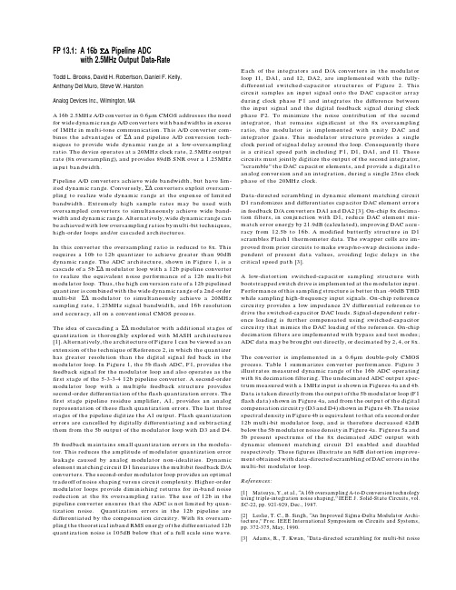
FP 13.1:A 16b Σ∆ Pipeline ADCwith 2.5MHz Output Data-RateTodd L. Brooks, David H. Robertson, Daniel F. Kelly,Anthony Del Muro, Steve W. HarstonAnalog Devices Inc., Wilmington, MAA 16b 2.5MHz A/D converter in 0.6µm CMOS addresses the need for wide dynamic range A/D converters with bandwidths in excess of 1MHz in multi-tone communication. This A/D converter com-bines the advantages of Σ∆ and pipeline A/D conversion tech-niques to provide wide dynamic range at a low-oversampling ratio. The device operates at a 20MHz clock rate, 2.5MHz output rate (8x oversampling), and provides 89dB SNR over a 1.25MHz input bandwidth.Pipeline A/D converters achieve wide bandwidth, but have lim-ited dynamic range. Conversely, Σ∆ converters exploit oversam-pling to realize wide dynamic range at the expense of limited bandwidth. Extremely high sample rates may be used with oversampled converters to simultaneously achieve wide band-width and dynamic range. Alternatively, wide dynamic range can be achieved with low oversampling ratios by multi-bit techniques, high-order loops and/or cascaded architectures.In this converter the oversampling ratio is reduced to 8x. This requires a 10b to 12b quantizer to achieve greater than 90dB dynamic range. The ADC architecture, shown in Figure 1, is a cascade of a 5b Σ∆ modulator loop with a 12b pipeline converter to realize the equivalent noise performance of a 12b multi-bit modulator loop. Thus, the high conversion rate of a 12b pipelined quantizer is combined with the wide dynamic range of a 2nd-order multi-bit Σ∆ modulator to simultaneously achieve a 20MHz sampling rate, 1.25MHz signal bandwidth, and 16b resolution and accuracy, all on a conventional CMOS process.The idea of cascading a Σ∆ modulator with additional stages of quantization is thoroughly explored with MASH architectures [1]. Alternatively, the architecture of Figure 1 can be viewed as an extension of the technique of Reference 2, in which the quantizer has greater resolution than the digital signal fed back in the modulator loop. In Figure 1, the 5b flash ADC, F1, provides the feedback signal for the modulator loop and also operates as the first stage of the 5-3-3-4 12b pipeline converter. A second-order modulator loop with a multiple feedback structure provides second-order differentiation of the flash quantization errors. The first stage pipeline residue amplifier, A1, provides an analog representation of these flash quantization errors. The last three stages of the pipeline digitize the A1 output. Flash quantization errors are cancelled by digitally differentiating and subtracting them from the 5b output of the modulator loop with D3 and D4. 5b feedback maintains small quantization errors in the modula-tor. This reduces the amplitude of modulator quantization error leakage caused by analog modulator non-idealities. Dynamic element matching circuit D1 linearizes the multibit feedback D/A converters. The second-order modulator loop provides an optimal tradeoff of noise shaping versus circuit complexity. Higher-order modulator loops provide diminishing returns for in-band noise reduction at the 8x oversampling ratio. The use of 12b in the pipeline converter ensures that the ADC is not limited by quan-tization noise. Quantization errors in the 12b pipeline are differentiated by the compensation circuitry. With 8x oversam-pling the theoretical inband RMS energy of the differentiated 12b quantization noise is 105dB below that of a full scale sine wave.Each of the integrators and D/A converters in the modulator loop I1, DA1, and I2, DA2, are implemented with the fully-differential switched-capacitor structures of Figure 2. This circuit samples an input signal onto the DAC capacitor array during clock phase P1 and integrates the difference between the input signal and the digital feedback signal during clock phase P2. To minimize the noise contribution of the second integrator, that remains significant at the 8x oversampling ratio, the modulator is implemented with unity DAC and integrator gains. This modulator structure provides a single clock period of signal delay around the loop. Consequently there is a critical speed path including F1, D1, DA1, and I1. These circuits must jointly digitize the output of the second integrator,“scramble” the DAC capacitor elements, and provide a digital to analog conversion and an integration, during a single 25ns clock phase of the 20MHz clock.Data-directed scrambling in dynamic element matching circuit D1 randomizes and differentiates capacitor DAC element errors in feedback D/A converters DA1 and DA2 [3]. On-chip 8x decima-tion filters, in conjunction with D1, reduce DAC element mis-match error energy by 21.9dB (calculated), improving DAC accu-racy from 12.5b to 16b. A modified butterfly structure in D1 scrambles Flash1 thermometer data. The swapper cells are im-proved from prior circuits to make swap/no-swap decisions inde-pendent of present data values, avoiding logic delays in the critical speed path [3].A low-distortion switched-capacitor sampling structure with bootstrapped switch drive is implemented at the modulator input. Performance of this sampling structure is better than -90dB THD while sampling high-frequency input signals. On-chip reference circuitry provides a low impedance 2V differential reference to drive the switched-capacitor DAC loads. Signal-dependent refer-ence loading is further compensated using switched-capacitor circuitry that mimics the DAC loading of the reference. On-chip decimation filters are implemented with bypass and test modes; ADC data may be brought out directly, or decimated by 2, 4, or 8x. The converter is implemented in a 0.6µm double-poly CMOS process. Table 1 summarizes converter performance. Figure 3 illustrates measured dynamic range of the 16b ADC operating with 8x decimation filtering. The undecimated ADC output spec-trum measured with a 1MHz input is shown in Figures 4a and 4b. Data is taken directly from the output of the 5b modulator loop (F1 flash data) shown in Figure 4a, and from the output of the digital compensation circuitry (D3 and D4) shown in Figure 4b. The noise spectral density in Figure 4b is equivalent to that of a second order 12b multi-bit modulator loop, and is therefore decreased 42dB below the 5b modulator noise density in Figure 4a. Figures 5a and 5b present spectrums of the 8x decimated ADC output with dynamic element matching circuit D1 enabled and disabled respectively. These figures illustrate an 8dB distortion improve-ment obtained with data-directed scrambling of DAC errors in the multi-bit modulator loop.References:[1]Matsuya, Y., et al., “A 16b oversampling A-to-D conversion technology using triple-integration noise shaping,” IEEE J. Solid-State Circuits, vol. SC-22, pp. 921-929, Dec., 1987.[2]Leslie, T. C., B. Singh, “An Improved Sigma-Delta Modulator Archi-tecture,” Proc. IEEE International Symposium on Circuits and Systems, pp. 372-375, May, 1990.[3]Adams, R., T. Kwan, “Data-directed scrambling for multi-bit noiseshaping D/A converters,” United States patent 5,412,387. 13-1-1:ADC block diagram.13-1-2:Switched-capacitor DAC and integrator.13-1-3:Performance vs. input level.13-1-4:Undecimated output spectrum.13-1-5:Decimated output spectrum.13-1-6:Chip micrograph.Resolution16bSample rate20MSample/s Oversampling ratio8xSNR (full-scale 1MHz input)89dBGrounded input noise0.6LSBTHD (full-scale 100kHz input)92.8dBSFDR (full-scale 100kHz input)97.1dBPower consumption550mWDie size 5.7x6.2mm²Process0.6µm double-poly CMOS 13-1-Table 1:Performance summary.。


Bibliography[1] A.M.Abo,Design for reliability of low-voltage,switched-capacity circuits.Ph.D.Thesis,University of California,Berkeley,1999[2] A.M.Abo,P.R.Gray,A1.5-V,10-bit,14.3-MS/s CMOS pipeline analog-to-digital converter.IEEE J.Solid-State Circuits34(5),599–606(1999)[3] B.K.Ahuja,An improved frequency compensation technique for CMOS operational ampli-fiers.IEEE J.Solid-State Circuits18(6),629–633(1983)[4]V.J.Arkesteijn,Analog front-ends for software-defined radio receivers.Ph.D.dissertation,University of Twente,2007[5]V.J.Arkesteijn,E.A.M.Klumperink,B.Nauta,Jitter requirements of the sampling clock insoftware radio receivers.IEEE Trans.Circuits Syst.(TCAS)II53(2),90–94(2006)[6] C.W.Barbour,Simplified PCM analog to digital converter using capacity charge transfer,inProc.of the Telemetering Conf.(1971),pp.4.1–4.11[7] A.Barna,D.I.Porat,Integrated Circuits in Digital Electronics(Wiley,New York,1973),pp.353–354[8]W.C.Black,D.A.Hodges,Time interleaved converter arrays.IEEE J.Solid-State Circuits15(6),1022–1029(1980)[9]M.Boulemnakher,E.Andre,J.Roux,F.Paillardet,A1.2V4.5mW10b100MS/s pipelinedADC in65nm CMOS,in ISSCC Dig.Tech.Papers(2008),pp.250–251[10]T.B.Cho,P.R.Gray,A10b,20Msample/s,35mW pipeline A/D converter.IEEE J.Solid-State Circuits30(3),166–172(1995)[11]R.H.Dennard,F.H.Gaensslen,H.N.Yu,V.L.Rideovt,E.Bassous,A.R.LeBlanc,Design ofion-implanted MOSFET’s with very small physical dimensions.IEEE J.Solid-State Circuits 256–268(1974)[12]S.Devarajan,L.Singer,D.Kelly,S.Decker,A.Kamath,P.Wilkins,A16b125MS/s385mW78.7dB SNR CMOS pipeline ADC,in ISSCC Dig.Tech.Papers(2009),pp.86–87 [13] A.G.F.Dingwall,Monolithic expandable6bit20MHz CMOS/SOS A/D converter.IEEE J.Solid-State Circuits14(6),926–932(1979)[14]M.El-Chammas,B.Murmann,General analysis on the impact of phase-skew in time-interleaved ADCs,in IEEE International Symposium on Circuits and Systems(ISCAS) (2008),pp.17–20[15]S.L.J.Gierkink,Control linearity and jitter of relaxation oscillators.Ph.D.dissertation,Uni-versity of Twente,1999[16]S.K.Gupta,M.A.Inerfield,J.Wang,A1-GS/s11-bit ADC with55-dB SNDR,250-MAWpower realized by a high bandwidth scalable time-interleaved architecture.IEEE J.Solid-State Circuits41(12),2650–2657(2006)[17]K.Hadidi,A.Khoei,A highly linear cascode-driver CMOS source-follower buffer,in IEEEIntl.Conf.on Electronics,Circuits and Systems(1996),pp.1243–1246S.M.Louwsma et al.,Time-interleaved Analog-to-Digital Converters,131 Analog Circuits and Signal Processing,DOI10.1007/978-90-481-9716-3,©Springer Science+Business Media B.V.2011132Bibliography [18] C.-C.Hsu,F.-C.Huang,C.-Y.Shih,C.C.Huang,Y.-H.Lin,C.-C.Lee,B.Razavi,An11b800MS/s time-interleaved ADC with digital background calibration,in ISSCC Dig.Tech.Papers(2007),pp.464–465[19] E.Iroaga,B.Murmann,L.Nathawad,A background correction technique for timing errors intime-interleaved analog-to-digital converters,in IEEE International Symposium on Circuits and Systems(ISCAS),vol.6(2005),pp.5557–5560[20] E.A.M.Klumperink,B.Nauta,Systematic comparison of HF CMOS transconductors.IEEETrans.Circuits Syst.II,Analog Digit.Signal Process.50(20),728–741(2003)[21]N.Kurosawa,H.Kobayashi,K.Maruyama,H.Sugawara,K.Kobayashi,Explicit analysisof channel mismatch effects in time-interleaved ADC systems.IEEE Trans.Circuits Syst.I, Fundam.Theory Appl.48(3),261–271(2001)[22] F.Kuttner,A1.2V10b20MSample/s non-binary successive approximation ADC in0.13µmCMOS,in ISSCC Dig.Tech.Papers(2002),pp.176–177[23]Y.Z.Lin,S.J.Chang,Y.T.Liu,C.C.Liu,G.Y.Huang,A5b800MS/s2mW asynchronousbinary-search ADC in65nm CMOS,in ISSCC Dig.Tech.Papers(2009),pp.80–81 [24]S.M.Louwsma,E.J.M.van Tuijl,M.Vertregt,B.Nauta,A1.6GS/s,16times interleavedtrack&hold with7.6ENOB in0.12µm CMOS,in Proc.ESSCIRC(2004),pp.343–346 [25]S.M.Louwsma,E.J.M.van Tuijl,M.Vertregt,B.Nauta,A1.35GS/s,10b,175mW time-interleaved AD converter in0.13µm CMOS,in Proceedings of the Symposium on Very Large Scale Integration(VLSI)Circuits(2007),pp.62–63[26]S.M.Louwsma,E.J.M.van Tuijl,M.Vertregt,B.Nauta,A time-interleaved track&holdin0.13µm CMOS sub-sampling a4GHz signal with43dB SNDR,in Proceedings of the Custom Integrated Circuits Conference(CICC)(2007),pp.329–332[27]S.M.Louwsma,A.J.M.van Tuijl,M.Vertregt,B.Nauta,A1.35GS/s,10b,175mW time-interleaved AD converter in0.13µm CMOS.IEEE J.Solid-State Circuits43(4),778–786 (2008)[28]J.McCreary,P.Gray,All-MOS charge redistribution analog-to-digital conversion techniques.IEEE J.Solid-State Circuits10(6),371–379(1975)[29] E.Mensink,E.A.M.Klumperink,B.Nauta,Distortion cancellation by polyphase multipathcircuits.IEEE Trans.Circuits Syst.I,Regul.Pap.52(9),1785–1794(2005)[30]G.E.Moore,Cramming more components onto integrated circuits,in Electronics(1965),pp.114–2117[31] B.Murmann,A/D converter trends:power dissipation,scaling and digitally assisted architec-tures,in Proceedings of the Custom Integrated Circuits Conference(CICC),(2008),pp.751–758[32] B.Murmann,ADC Performance Survey1997–2009.Available online:http://www./~murmann/adcsurvey.html(2009)[33]K.Nagaraj, D.A.Martin,M.Wolfe,R.Chattopadhyay,S.Pavan,J.Cancio,T.R.Viswanathan,A dual-mode700-Msamples/s6-bit200-Msamples/s7-bit A/D converter in a0.25-µm digital CMOS process.IEEE J.Solid-State Circuits35(12),1760–1768(2000) [34]Y.Nakagome,H.Tanaka,K.Takeuchi,E.Kume,Y.Watanabe,T.Kaga,Y.Kawamoto,F.Murai,R.Izawa,D.Hisamoto,T.Kisu,T.Nishida,E.Takeda,K.Itoh,Experimental1.5-V 64-Mb DRAM.IEEE J.Solid-State Circuits26(4),465–472(1991)[35] B.Nauta,Analog CMOS low power design considerations,in Low Power Workshop on ES-SCIRC Conference(1996)[36] B.Nikoli´c,V.G.Oklobdžija,V.Stojanovi´c,W.Jia,J.K.S.Chiu,M.M.T.Leung,Improvedsense-amplifier-basedflip-flop:design and measurements.IEEE J.Solid-State Circuits35(6), 876–884(2000)[37]H.Pan,M.Segame,M.Choi,J.Cao,A.A.Abidi,A3.3-V12-b50-MS/s A/D converter in0.6-µm CMOS with over80-dB SFDR.IEEE J.Solid-State Circuits35,1769–1780(2000) [38]M.J.M.Pelgrom,A.C.J.Duinmaijer,A.P.G.Welbers,Matching properties of MOS transis-tors.IEEE J.Solid-State Circuits24(5),1433–1439(1989)Bibliography133 [39]K.Poulton,J.J.Corcoran,T.Hornak,A1-GHz6-bit ADC System.IEEE J.Solid-State Cir-cuits22(6),962–970(1987)[40]K.Poulton,R.Neff,B.Setterberg,B.Wuppermann,T.Kopley,R.Jewett,J.Pernillo,C.Tan,A.Montijo,A20GS/s8b ADC with a1MB memory in0.18µm CMOS,in ISSCC Dig.Tech.Papers(2003),pp.318–496[41] B.Razavi,Rf Microelectronics(Prentice Hall,New York,1998)[42] D.Schinkel,E.Mensink,E.A.M.Klumperink,A.J.M.van Tuijl,B.Nauta,A double-taillatch-type voltage sense amplifier with18ps setup+hold time,in ISSCC Dig.Tech.Papers (2007),pp.314–315[43] D.Schinkel,E.Mensink,E.A.M.Klumperink,A.J.M.van Tuijl,B.Nauta,A low-offsetdouble-tail latch-type voltage sense amplifier,in Proceedings of the18th ProRisc Workshop (2007)[44]H.Schmidt,Analog-Digital Conversion(Van Nostrand-Reinholt,New York,1970)[45] A.J.Scholten,G.D.J.Smit,B.A.D.Vries,L.F.Tiemeijer,J.A.Croon,D.B.M.Klaassen,R.van Langevelde,X.Li,W.Wu,G.Gildenblat,The new CMC standard compact MOS model PSP:advantages for RF applications,in IEEE Radio Frequency Integrated Circuits Symposium(2008),pp.247–250[46]T.Sepke,P.Holloway,C.G.Sodini,H.S.Lee,Noise analysis for comparator-based circuits.IEEE Trans.Circuits Syst.I,Regul Pap.56,541–553(2009)[47]R.C.Taft,P.A.Francese,M.R.Tursi,O.Hidri,A.MacKenzie,T.Hoehn,P.Schmitz,H.Werker,A.Glenny,A1.8V1.0GS/s10b self-calibrating unified-folding-interpolatingADC with9.1ENOB at Nyquist frequency,in ISSCC Dig.Tech.Papers(2009),pp.78–79 [48]H.P.Tuinhout,G.Hoogzaad,M.Vertregt,R.L.J.Roovers,C.Erdmann,Design and character-ization of a high precision resistor ladder test structure,in Proceedings of the IEEE Interna-tional Conference on Microelectronic Test Structures(ICMTS),vol.15(2002),pp.223–228 [49]R.C.H.van de Beek,High-speed low-jitter frequency multiplication in CMOS.Ph.D.disser-tation,University of Twente,2004[50]R.J.van de Plassche,Integrated Analog-to-Digital and Digital-to-Analog Converters(Kluwer Academic,Dordrecht,1994)[51]R.J.van de Plassche,R.E.J.van der Grift,A high-speed7bit A/D converter.IEEE J.Solid-State Circuits14(6),938–943(1979)[52]G.van der Plas,B.Verbruggen,A150MS/s133µW7b ADC in90nm digital CMOS using acomparator-based asynchronous binary-search sub-ADC,in ISSCC Dig.Tech.Papers(2008), pp.242–243[53]H.van der Ploeg,Calibration techniques in two-step a/d converters.Ph.D.dissertation,Uni-versity of Twente,2005[54]M.van Elzakker,A.J.M.van Tuijl,P.F.J.Geraedts,D.Schinkel,E.A.M.Klumperink,B.Nauta,A1.9µW4.4fJ/conversion-step10b1MS/s charge-redistribution ADC,in ISSCCDig.Tech.Papers(2008),pp.245–245[55] A.J.M.van Tuijl,personal communication[56] A.Verma,B.Razavi,A10b500MHz55mW CMOS ADC,in ISSCC Dig.Tech.Papers,(2009),pp.84–85[57]M.Vertregt,The analog challenge of nanometer CMOS,in International Electron DevicesMeeting(IEDM)(2006),pp.1–8[58]M.Vertregt,H.P.Tuinhout,personal communication[59]Video-transcript,Excerpts from a conversation with Gordon Moore:Moore’s law.ftp:///museum/Moores_Law/Video-Transcripts/Excepts_A_Conversation _with_Gordon_Moore.pdf(2005)[60]R.H.Walden,Analog-to-digital converter survey and analysis.IEEE J.Sel.Areas Commun.17(4),539–550(1999)[61] B.Wicht,T.Nirschl,D.Schmitt-Landsiedel,Yield and speed optimization of a latch-typevoltage sense amplifier.IEEE J.Solid-State Circuits39(7),1148–1158(2004)134Bibliography [62]Wikipedia,Orthogonal frequency-division multiplexing./wiki/Orthogonal_frequency-division_multiplexing(2009)[63]K.L.J.Wong,C.K.K.Yang,Offset compensation in comparators with minimum input-referred supply noise.IEEE J.Solid-State Circuits39(5),837–840(2004)[64]W.Yang,D.Kelly,L.Mehr,M.T.Sayuk,L.Singer,A3-V340-mW14-b75-Msample/sCMOS ADC with85-dB SFDR at Nyquist input.IEEE J.Solid-State Circuits36(12),1931–1936(2001)Index3D EM-field simulation,16AAD-Convertercounting,40flash,3,39,93folding,39pipeline,28,29,31,40,45,48,59,63–68, 93SA-ADC,40–57,91,94–108slope,40two-step,40amplifier,40,59,64,92,93,122interstage,108–111architectureTrack&Holdwith frontend sampler,17–20without frontend sampler,13–17Bbandwidthinput,16,19,30body effect,23bootstrapping,78–85bottom-plate sampling,6,28,29bufferbandwidth requirement,26distortion,23implementation,90input,14open-loop,22source follower,23,24,26,38,90,91Ccalibration,32–35,58,72,85,113,115,118 background,33bandwidth,12,22,35foreground,33gain,34,114offset,34,57,63,114,115timing,34,121,123 capacitancebuffer,input,25input,13,15–17interconnect,9capacitive load,26channel-charge injection,80,84,85 charge redistribution,27,83,110,111 clock feed-through,84,85clock generation,68,72,73,75,88,95 comparator,54–57,59,97,98Ddecoder,105digital control,40,41,94,99Eerrorgain,5offset,5timing,5Ffeedback,22Hhold-mode,5Jjitter,34–37,73,78,85,120,121,123S.M.Louwsma et al.,Time-interleaved Analog-to-Digital Converters,Analog Circuits and Signal Processing,DOI10.1007/978-90-481-9716-3,©Springer Science+Business Media B.V.2011135136IndexLladder connections,106layout,15,16,86,116look-ahead logic,53,99,101,103Mmatchingcapacitor,10Miller effect,25,109mismatchbandwidth,9–12between channels,6gain,6,7offset,6timing,6Nnoiseamplifier,64kT/C,16,58–61,64,85,111variance,59,64–66non-interleaved,5,6,22,26,30,39,68Ooffsetchannel,6comparator,57opamp,28,29,31,57,58,63,67,91,93,104, 108,109Pphase-differences,8Rreliability,79,82,83reset switch,15resistanceinterconnect,9switch,9,10,19,51,79Ssettling,14settling time,19,28,41–44,48,49single-sided overrange technique,46,47,49, 94,99,101spectrum,6spurious tones,6switchto avoid distortion,27switch-driver,85Ttechnology,10,14,16,19,22,32timing-misalignment,8,17Track and Holdbuffer,22–28track-mode,5track-timereduction,14,18track-time reduction,29 transconductance amplifier,59 transmission lines,13。
10位10MHz自校准SAR_ADC设计自校准是现代电子系统设计中的重要技术之一,它可以提高系统的稳定性和准确性。
而SAR_ADC(逐次逼近式寄存器型模数转换器)作为一种常用的模拟数字转换器,在许多应用中发挥着重要作用。
本文将介绍一种10位10MHz自校准SAR_ADC的设计。
首先,我们需要了解SAR_ADC的基本原理。
SAR_ADC是一种逐次逼近式模数转换器,它通过逐次调整比较器的参考电压和DAC(数模转换器)的输出来逼近输入信号的模拟电压。
在每次逼近过程中,比较器会将输入信号与参考电压进行比较,并将比较结果输入给逻辑电路。
逻辑电路会根据比较结果调整DAC 的输出,从而逼近输入信号的模拟电压。
最终,DAC的输出值就是输入信号的数字表示。
为了实现自校准,我们需要添加校准电路和控制逻辑。
校准电路可以根据已知的参考电压和已知的输入信号,通过比较器和DAC的输出,计算出比较器和DAC的误差,并将误差值送回控制逻辑。
控制逻辑会根据误差值调整比较器的参考电压和DAC 的输出,以校正比较器和DAC的误差。
通过多次校准过程,SAR_ADC的准确性和稳定性将得到显著提高。
在10位10MHz的设计中,关键是要保证高精度和高速率。
为了实现高精度,我们可以使用高精度的比较器和DAC,并增加比较器的位数。
为了实现高速率,我们可以优化控制逻辑和校准算法,使其能够在10MHz的采样率下完成校准和转换过程。
此外,我们还可以采用一些技术手段来进一步提高SAR_ADC的性能。
例如,我们可以使用电流平衡技术来降低比较器和DAC的误差,使用自适应校准算法来动态调整校准过程,以适应不同的工作条件。
同时,我们还可以使用电源抑制技术来降低电源噪声对转换精度的影响。
综上所述,10位10MHz自校准SAR_ADC的设计是一个复杂而关键的任务。
通过合理选择器件和优化设计,结合适当的校准算法和技术手段,我们可以实现高精度和高速率的SAR_ADC。
摘要模数转换器(ADC)作为现代通信系统中的关键电路,其性能直接决定了通信系统的整体性能。
在需要中等精度高速ADC的应用场合,如无线网802.11ac通信协议等,流水线逐次逼近型模数转换器(Pipeline-SAR ADC)以其兼顾高速和低功耗的结构特点、对先进工艺兼容良好等优良特性被广泛使用。
针对现代高速通信系统的应用场合,论文设计了一款10bit 500MS/s的Pipeline-SAR ADC,其系统架构为两级结构,两级SAR ADC都实现6bit的数据量化,级间放大器提供4倍增益,设置2bit 级间冗余。
在第一级SAR ADC中,提出了一种基于自关断比较器的非环路(Loop-unrolled)结构,在每位比较完成后,通过自关断信号将当前位比较器关断,在不影响比较器锁存级保持数据的前提下,极大减小了Loop-unrolled结构的功耗;同时,针对Loop-unrolled结构多个比较器之间的失调失配,采用了一种基于参考比较器的后台失调校准方法,参考比较器的引入使得该校准方法可以在不增加额外校准时间的前提下完成后台校准,保证了系统的高速特性。
级间放大器采用了一种增益稳定的动态放大器,通过将动态放大器的增益构造为同种参数比例乘积的形式,实现增益稳定,并对其工作时序进行了优化,避免了额外时钟相的引入。
第二级SAR ADC采用了两路交替比较器结构,同时对两个比较器采用了前台失调校准,以避免引入额外的校准时间。
由于级间放大器仅提供4倍增益,第二级的量化范围较小,本文在第二级电容阵列的设计上使用了非二进制冗余,以减小DAC建立误差造成的影响。
本文还设计了数字码整合电路、全局时钟产生电路,以保证整个Pipeline-SAR ADC设计的完整性。
本文基于TSMC 40nm CMOS工艺设计了具体的电路与版图。
后仿真结果表明,在1.1V电源电压下,采样率为500MS/s时,输入近奈奎斯特频率的信号,在tt工艺角下,有效位数(ENOB)达到9.2位,无杂散动态范围(SFDR)达到64.5dB,功耗为7.52mW,FoM值为25.76fJ/conv.step,达到设计指标要求。
pipeline-sar adc 原理-回复Pipelines是一种在计算机科学中广泛使用的概念,旨在优化数据处理和计算任务的执行效率。
在本文中,我们将专注于pipelines在应用程序设计中的应用,特别是在ADC(模数转换器)中的原理。
首先,让我们了解一下ADC的基本原理。
ADC是一种将模拟信号转换为数字信号的电子设备。
在许多应用中,如音频和视频处理,传感器数据采集等,我们需要将连续时间的模拟信号转换为离散时间的数字信号,以便进行进一步的处理。
ADC通常由三个主要部分组成:采样和保持电路(S&H),模数转换器(ADC),数字信号处理器(DSP)。
在这些部分中,ADC是其中最核心的组件,因为它实现了模拟到数字的转换。
ADC的基本原理是通过将模拟信号离散化为一系列离散时间点的取样值,然后将这些取样值转换为相应的数字表示。
这个过程可以分为三个主要的步骤:采样,量化和编码。
采样是将模拟信号在时间上分割成多个取样点的过程。
为了保持信号的准确性,ADC使用采样和保持电路(S&H)来获取每个取样点的电压或电流值。
采样速率决定了信号从模拟到数字的转换的精度。
更高的采样速率可以提供更准确的数字表示,但同时也需要更多的计算和存储资源。
量化是将连续的模拟信号转换为离散的数字表示。
在此过程中,ADC将每个取样点的模拟信号值映射到最近的可用数字值。
量化的精度通常由ADC 的位数来决定。
例如,一个12位ADC将模拟信号映射到4096个离散的数字值。
较高的位数可以提供更精确的量化结果,但也需要更多的存储空间和计算资源。
编码是将量化后的数字值转换为二进制码表示的过程。
在这步中,ADC将量化后的数字值转换为相应的二进制码。
编码通常采用二进制补码表示,以便进行进一步的数字信号处理。
编码的格式通常取决于ADC的设计和应用。
在ADC设计中,pipelines广泛应用于提高转换速率和精度。
一个典型的ADC pipeline结构包含多个级别,每个级别都包含采样,量化和编码等子功能。