基于UCC28710型号具有一次侧稳压功能的恒压、恒流控制器
- 格式:pdf
- 大小:103.78 KB
- 文档页数:7
IMPORTANT NOTICETexas Instruments Incorporated and its subsidiaries(TI)reserve the right to make corrections,modifications,enhancements,improvements, and other changes to its products and services at any time and to discontinue any product or service without notice.Customers should obtain the latest relevant information before placing orders and should verify that such information is current and complete.All products are sold subject to TI’s terms and conditions of sale supplied at the time of order acknowledgment.TI warrants performance of its hardware products to the specifications applicable at the time of sale in accordance with TI’s standard warranty.Testing and other quality control techniques are used to the extent TI deems necessary to support this warranty.Except where mandated by government requirements,testing of all parameters of each product is not necessarily performed.TI assumes no liability for applications assistance or customer product design.Customers are responsible for their products and applications using TI components.To minimize the risks associated with customer products and applications,customers should provide adequate design and operating safeguards.TI does not warrant or represent that any license,either express or implied,is granted under any TI patent right,copyright,mask work right, or other TI intellectual property right relating to any combination,machine,or process in which TI products or services are rmation published by TI regarding third-party products or services does not constitute a license from TI to use such products or services or a warranty or endorsement e of such information may require a license from a third party under the patents or other intellectual property of the third party,or a license from TI under the patents or other intellectual property of TI.Reproduction of TI information in TI data books or data sheets is permissible only if reproduction is without alteration and is accompanied by all associated warranties,conditions,limitations,and notices.Reproduction of this information with alteration is an unfair and deceptive business practice.TI is not responsible or liable for such altered rmation of third parties may be subject to additional restrictions.Resale of TI products or services with statements different from or beyond the parameters stated by TI for that product or service voids all express and any implied warranties for the associated TI product or service and is an unfair and deceptive business practice.TI is not responsible or liable for any such statements.TI products are not authorized for use in safety-critical applications(such as life support)where a failure of the TI product would reasonably be expected to cause severe personal injury or death,unless officers of the parties have executed an agreement specifically governing such use.Buyers represent that they have all necessary expertise in the safety and regulatory ramifications of their applications,and acknowledge and agree that they are solely responsible for all legal,regulatory and safety-related requirements concerning their products and any use of TI products in such safety-critical applications,notwithstanding any applications-related information or support that may be provided by TI.Further,Buyers must fully indemnify TI and its representatives against any damages arising out of the use of TI products in such safety-critical applications.TI products are neither designed nor intended for use in military/aerospace applications or environments unless the TI products are specifically designated by TI as military-grade or"enhanced plastic."Only products designated by TI as military-grade meet military specifications.Buyers acknowledge and agree that any such use of TI products which TI has not designated as military-grade is solely at the Buyer's risk,and that they are solely responsible for compliance with all legal and regulatory requirements in connection with such use. TI products are neither designed nor intended for use in automotive applications or environments unless the specific TI products are designated by TI as compliant with ISO/TS16949requirements.Buyers acknowledge and agree that,if they use any non-designated products in automotive applications,TI will not be responsible for any failure to meet such requirements.Following are URLs where you can obtain information on other Texas Instruments products and application solutions:Products ApplicationsAudio /audio Automotive and Transportation /automotiveAmplifiers Communications and Telecom /communicationsData Converters Computers and Peripherals /computersDLP®Products Consumer Electronics /consumer-appsDSP Energy and Lighting /energyClocks and Timers /clocks Industrial /industrialInterface Medical /medicalLogic Security /securityPower Mgmt Space,Avionics and Defense /space-avionics-defense Microcontrollers Video and Imaging /videoRFID OMAP Mobile Processors /omapWireless Connectivity /wirelessconnectivityTI E2E Community Home Page Mailing Address:Texas Instruments,Post Office Box655303,Dallas,Texas75265Copyright©2012,Texas Instruments Incorporated。

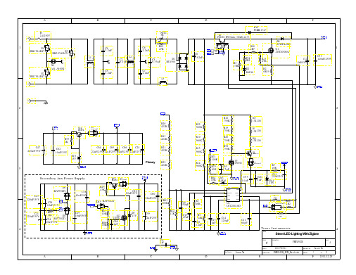
TI UCC28810 110W离线LED照明解决方案TI公司的UCC28810和UCC28811是通用照明电源控制器,能以临界导通模式控制反激,降压或升压转换器,集成了用于反馈误差处理的跨导,参考发生器,电流检测(),PWM规律和用来驱动外接FET的图腾柱驱动器.主要用在HB 照明,工业,商业和住所区照明以及室外照明.本文介绍了UCC28810/1主要特性, 方框图, 简化应用以及110W离线AC/DC LED驱动器UCC28810EVM-003主要特性,图,材料清单和布局图.The UCC28810 and UCC28811 are general lighting power controllers for low to medium power lumens applications requiring power factor correction and compliance. It is designed forcontrolling a flyback, buck or boost converter operating in critical conduction mode. It features a transconductance voltage amplifier for feedback error processing, a simple currentreference generator for generating a current command proportional to the input voltage, a current-sense (PWM) comparator, PWM logic and a totem-pole driver for driving an external FET.In the critical conduction mode operation, the PWM circuit is self-oscillating with the turn-on being governed by a transformer zero energy detector (TZE pin) and the turn-off being governed by the current sense comparator.UCC28810/1主要特性:Transition Mode Controller for Low Implementation Cost of AC Input LED Lighting ApplicationsImplements Single Stage Power Factor Corrected LED Driver Enhanced Transient Response With Slew-Rate Comparator Interfaces with Traditional Wall DimmersAccurate Internal VREF for Tight Output Regulation第1页共2页。

uc2875dwp原理一、概述UC2875DWP是一种高性能的低压差稳压器(LowDropoutRegulator,简称LDO),它广泛应用于各种电子设备中,如移动设备、物联网设备、数码相机等。
本章节将介绍UC2875DWP 的基本原理、特点和应用。
二、工作原理1.输入输出关系:UC2875DWP的基本工作原理是通过控制电流来调整输出电压。
在正常情况下,输入电压(Vin)与输出电压(Vout)之间存在一定的压差,该压差由电阻和电感等元件的功耗决定。
当电流流过这些元件时,会消耗一定的能量,从而降低输出电压。
2.反馈机制:UC2875DWP使用内部电压监控器作为反馈机制,它能够实时检测输出电压并与参考电压进行比较。
如果输出电压偏离设定值,监控器会自动调整内部的控制环路,从而调节输入电流和输出电压,以达到稳定的输出状态。
3.调整率:由于元器件特性和工艺误差等因素,UC2875DWP会有一定的调整率。
调整率是指在负载和环境温度变化的情况下,输出电压的变化范围。
在实际应用中,需要根据具体应用场景和负载特性来选择合适的UC2875DWP型号,并校准调整率。
三、特点1.低压差工作:UC2875DWP能够在很低的压差下工作,通常在0.4V至1.2V之间。
这使得它适用于对功耗有严格要求的电子设备中。
2.高效率:UC2875DWP具有较高的转换效率,能够在保证稳定输出的同时,减少能源的浪费。
3.内部集成:UC2875DWP内部集成了多种功能,如基准电压源、保护电路等,减少了外部元件的数量,简化了电路设计。
4.宽工作温度范围:UC2875DWP具有较宽的工作温度范围,可以在-40℃至+125℃的温度范围内正常工作。
四、应用UC2875DWP广泛应用于各种需要稳定电压输出的电子设备中,如移动设备、数码相机、物联网设备等。
在这些应用中,UC2875DWP可以提供稳定的电压输出,保证设备的正常运行,同时降低功耗和能源浪费。
分享:电源充电器和通用USB充电选择优化方案
就移动设备电源适配器而言,低于15W的低功耗产品占据了绝对的市场份额。
随着智能手机和平板电脑的电池容量越来越大,对充电器输出电流的要求已经从以往的200mA~300mA上升至1A或者2.1A,5W的输出功率已经是目前智能手机充电器的主流规格。
在低功耗方面,早在2008年,欧盟委员会的整合性产品政策(EC IPP)即与全球5家OEM共同制定了环保性电池充电器评级体系,空载功耗除了低功耗,欧盟还一直在推动USB电池充电的统一化进程,最新的规范BCS 1.2版则希望所有出口到欧洲的平板电脑和智能手机都能使用一个USB端口进行充电,这是一个强制化的标准,预计2014年将有90%的移动设备电源适配器符合该标准。
基于这些趋势,TI不久前发布了其首个空载功耗
低功耗充电控制方案及其特性
UCC28700能够实现更小的方形适配器、无线电源充电站以及其它交流供电设备,TPS2511符合USB电池充电规范1.2版,适用于智能手机或5V平板电脑的充电适配器。
据TI半导体事业部业务发展经理程文涛介绍,
UCC28700是一款恒压恒流的反激式PFM(脉冲频率调制)控制器,而PFM方式是目前初级侧控制器最好的做法。
UCC28700的待机功耗低于30mW,只需1.5μA的启动电流,这也是能够实现空载功耗<30mW 的关键。
由于是初级侧调节,所以无需光耦反馈电路,并且其VDD输入电压很宽(8V~35V),迟滞范围低,IDD待机电流也很低,这使得充电器可以使用更小的VDD电容器(只需要330μF即可),从而减少了体积和成本。
另外,UCC28700的开关。

用LLC半桥式控制器UCC25710实现LED照明一、UCC25710:LED 照明用LLC 半桥式控制器快速入门指南TI UCC25710是一款用于实现多串LED背光源应用的准确控制的LLC半桥式控制器。
它专为多变压器、多串LED架构而优化。
利用该控制器及架构可在多个LED串中实现绝佳的LED电流匹配。
与现有的LED背光源解决方案相比,这种多变压器架构可依靠AC输入向LED 负载提供最高的总效率。
LLC控制器的功能包括一个具有可编程F的压控振荡器(VCO)最小值和F最大值、具有500ns固定死区时间的半桥式栅极驱动器和一个GM电流放大器。
LLC功率输送由控制器的VCO频率来调整。
该VCO具有一个准确且可编程的频率范围。
在超低的功率电平下,VCO频率从F变最大值至零,以最大限度地提高低LED电流条件下的效率。
特性:可调节 F最小值(3% 准确度),和 F最大值(7.5%准确度)用于调光的 LLC 和串联 LED 开关控制用于消除可听噪声的可编程调光 LLC ON/OFF 斜坡低调光占空比条件下的闭环电流控制可编程软启动准确的 VREF 用于实现严格的输出调节具有自动再起动响应的过压、欠压和输入过流保护具有锁断响应的第二过流门限400mA/-800mA 栅极驱动电流低启动电流及工作电流无铅型 20 引脚 SOIC 封装应用:用于LCDTV和监视器的LED背光源LED通用照明二、UCC25710:LED 照明用LLC 半桥式控制器应用详解设计采用TIUCC25710多串变压器LLC控制专利技术,实现了新型离线式LED照明驱动解决方案。
相比传统的高功率(>100W)的AC/DC外加多个恒流DC/DC转换器的LED照明驱动,新的两级拓扑结构具有更高的效率以及更低的系统成本。
基于该种多串变压器LLC 控制技术,研发了一款100WLED照明驱动参考设计PMP4302A,其负载可以直接连接4串LED负载(每串可接10~15颗LED,每串输出电流为500mA)。
化工自动化控制仪表考试题库(含答案)1、【单选题】CENTUMCS3000R3系统中,一个域是一个逻辑控制网部分。
用户可以用()连接不同域。
(A)A、总线转换器BCVB、现场控制站FCSC、通讯网关单元CGW2、【单选题】CENTUMCS3000R3系统中,系统状态画面显示设备信息为黄色时,表示该设备()。
(B)A、有故障,但能工作B、备用状态C、有故障,不能工作3、【单选题】CENTUMCS3000系统中,在控制分组画面上不可以进行()操作。
(C)A、修改控制模式MODEB、修改SP值C、将过程点打校验状态4、【单选题】CENTUMCS3000系统的现场控制单元FCU中,处理器卡执行控制计算并监视CPU及供电单元,其上的状态指示灯COPY在()情况下会亮。
(C)A、备用时B、软硬件都正常时C、复制数据时5、【单选题】Tristation1131是()公司的控制组态软件。
(A)A、TRICONEXB、ICSC、GE6、【单选题】一次仪表、电缆护套管、电缆的安装尽可能地远离高温工艺设备和工艺管道、对它们的影响较大的为()。
(B)A、温差B、温度C、热量7、【单选题】下面关于串级控制系统副变量的描述错误的是()。
(B)A、在主变量确定后,选择的副变量应与主变量间有一定的内在联系B、在串级系统中,副变量的变化应尽量不影响主变量的变化C、选择与主变量有一定关系的某一中间变量作为副变量8、【单选题】下面关于串级控制系统特点的描述中正确的是()。
(B)A、系统的目的是通过设置主变量来提高对副变量的控制质量B、在系统结构上是由两个串接工作的控制器构成的双闭环负反馈控制系统C、由于副回路的存在,对于进入主回路的干扰有超前控制作用,因而减少了干扰对主变量的影响9、【单选题】下面是关于负压(真空度)的表达式,其中正确的表达式是()。
(A)A、P负=P大-P绝。
B、P负=P表+P大C、P负=P绝-P表10、【单选题】为了保证测量精确度,正常操作压力值应不低于压力表满量程的()。
100Dimming Duty Cycle -%8095100108590E f f i c i e n c y -%-424-2L i n e a r i t y E r r o r -%Efficiency and Linearity Results(Dual 45-W Strings)用于多串LED 照明的LLC 半桥式控制器查询样品:UCC25710特性应用•闭环LED 串电流控制•用于LCD TV 和监视器的LED 背光源•PWM 调光输入•LED 通用照明•可调节F 最小值(3%准确度),和F 最大值(7.5%说明准确度)UCC25710是一款用于实现多串LED 背光源应用的准•用于调光的LLC 和串联LED 开关控制确控制的LLC 半桥式控制器。
它专为多变压器、多串•用于消除可听噪声的可编程调光LLC ON/OFF 斜坡LED 架构而优化。
利用该控制器及架构可在多个LED •低调光占空比条件下的闭环电流控制串中实现绝佳的LED 电流匹配。
与现有的LED 背光•可编程软启动源解决方案相比,这种多变压器架构可依靠AC 输入向•准确的V REF 用于实现严格的输出调节LED 负载提供最高的总效率。
•具有自动再起动响应的过压、欠压和输入过流保护LLC 控制器的功能包括一个具有可编程F 的压控振荡•具有锁断响应的第二过流门限器(VCO)最小值和F 最大值、具有500ns 固定死区时间的•400mA/-800mA 栅极驱动电流半桥式栅极驱动器和一个GM 电流放大器。
LLC 功率•低启动电流及工作电流输送由控制器的VCO 频率来调整。
该VCO 具有一个•无铅型20引脚SOIC 封装准确且可编程的频率范围。
在超低的功率电平下,VCO 频率从F 变最大值至零,以最大限度地提高低LED 电流条件下的效率。
Simplified Application DiagramPlease be aware that an important notice concerning availability,standard warranty,and use in critical applications of Texas Instruments semiconductor products and disclaimers thereto appears at the end of this data sheet.UCC25710ZHCS125A–APRIL2011–REVISED DESCRIPTION(CONT.)The LED current loop reference is set by a divider off the V REF5-V output.The reference can be varied over a 0.5V to2.6V range,allowing analog dimming to be combined with PWM dimming.PWM dimming is used to control an external LED series switch and also to gate on and off the LLC power stage. The LEDSW output along with a simple drive circuit is used to switch on and off the LED string current.This output responds directly to the input signal at the dimming input,DIM.The LLC is also ramped on and off with the dimming PWM input.The on and off LLC dimming edges are ramped at programmable slew rates to control audible noise.The dimming function includes duty-cycle compensation to allow optimization of overall efficiency and dimming linearity over a maximum range.The control voltage to the VCO is set by ICOMP(current amplifier output)during LED on-times.During start-up the soft-start pin,SS,will control the VCO response until it exceeds ICOMP.During dimming the rise and fall rates of the VCO input are controlled by the voltage at the dimming slew rate,DSR,pin while the pedestal of VCO control level will continue to be controlled by ICOMP.The current amplifier output is connected to ICOMP only during the commanded dimming LED on-time.The LLC on-time is extended beyond the LED current on-time at low dimming duty-cycles to maintain closed loop control of the LED current.Protection thresholds for LED string over-voltage and under-voltage conditions are set with external resistive dividers and accurate internal thresholds.Input current to the converter is monitored with both a re-start and latch-off response depending on the over-current level.The controller also includes thermal shutdown protection. The auto re-start response to any fault includes a10-ms reset period followed by a soft-start.In the case of a severe input over-current,restart will be disabled until the input supply is cycled through its UVLO threshold.这些装置包含有限的内置ESD保护。
ucc28740工作原理
UCC28740是一款恒定熔断电源控制器,广泛应用于电源适配器、电池充电器和可移动充电设备等系统中。
它采用了混合电压和电流模式控制,具有高精度的恒定电流输出和过电流保护功能。
其工作原理如下:
1. 开关控制:UCC28740通过内部的开关管控制电源的开关状态。
当开关管导通时,输入电压源通过变压器传递给输出端。
当开关管关断时,变压器上的能量释放到输出端。
2. 混合电压和电流模式控制:UCC28740可以根据外部电流传感器的反馈信号,实时监测和调整输出电流。
当输出电流超过设定限制时,控制器会启动过电流保护功能,以保护电源和负载。
3. 恒定电流输出:UCC28740通过调整开关管的导通和关断时间,实现恒定电流输出。
当输出电压减小时,控制器增加开关管的导通时间,使输出电流保持不变。
4. 过电流保护:当输出电流超过设置的限制值时,控制器会立即启动过电流保护。
它会减少开关管的导通时间,以降低输出电流,防止损坏电源和负载。
5. 其他保护功能:UCC28740还具有过温保护和过电压保护等功能,以确保电源和负载的安全运行。
总的来说,UCC28740通过混合电压和电流模式控制,实现了恒定熔断功能,保护电源和负载。
基于UCC28710型号具有一次侧稳压功能的恒压、恒
流控制器
描述
UCC2871x 系列反激式电源控制器在不使用光耦合器的情况下提供隔离式输出恒压(CV) 和恒流(CC) 输出调节。
此器件可处理来自主要电源开关和辅助反激式绕组的信息,以对输出电压和电流进行精确控制。
一个内部700V 启动开关、动态控制的工作状态和一个定制的调制配置文件在不牺牲启动时间或输出瞬态响应的同时支持超低待机功耗。
UCC28710 系列中的控制算法使得运行效率符合或者超过适用标准。
输出驱动接至一个MOSFET 电源开关。
带有谷值开关的断续传导模式(DCM) 减少了开关损耗。
开关频率的调制和初级电流峰值振幅(FM 和AM) 在整个负载和线路范围内保持较高的转换效率。
此控制器有一个100kHz 的最大开关频率并且一直保持对变压器内初级峰值电流的控制。
保护功能有助于抑制一次侧和二次侧应力分量。