霍尼韦尔全热交换器EcoGreen-ER_cn说明书
- 格式:pdf
- 大小:1.21 MB
- 文档页数:10


DT100FRM/FRSxxxA系列2线数字式风机盘管&地采暖温控器控制点(最多15 区)产品说明应用DT100FRM/FRS数字式温控器被设计为通过ON /OFF控制MCV阀和FCU阀以及2线风机盘管的应用。
MC100FR接线盒子被设计为由DT100FRM/FR S温控器连接通过ON/OFF控制MCV阀运用于地采暖系统上。
该系列温控器外观设计新颖、具有液晶显示、功能多样、简单易用。
该温控器通过控制阀门的开/关而使室温达到设定值。
DT100FRM(主区温控器)可控制并监控其它最多14个DT100FRS(分区温控器)温控器的模式是可持续利用的循环操作,并且有高、中、低三级风速选择。
风扇可以通过ON/OFF来打开关闭加热/制冷的转换可以通过DT100FRM(主区温控器)左边的开关来转换。
特点●带数字显示的典雅外形;●可显示室温及用户设定的温度;●拨盘用于调整温度设定;●可以设定成待机模式,直到再次触及任一一键,以便节省能源;●冷热的转换通过滑动开关调节;●通过滑动开关来手动调节风速;●具有每小时开启功能,此功能命令通过记时器模式操作;.●具有预约功能,可在预定时间自动开启(0-24小时)●温控器可直接通过2×4接线盒安装于墙上;.●采用EEPROM 存储器,即使在停电时亦可保存用户设置;●用于MCV2000/2500系列,VC4000/6000系列,V4043/4044阀体和压缩起动器/全负荷的继电器。
目录应用 (1)特点 (1)规格 (2)尺寸 (2)安装 (3)接线图 (4)操作 (5)DT100FRM DT100FRS规格表 1. 型号指南 型号 描述/应用 电压 DT100FRM151A 用于风扇&风机盘管操作的主区温控器(15 zone) DC12V (由 MC100FR 提供) DT100FRM251A 用于循环风扇&风机盘管操作的主区温控器 (15 zone) DT100FRS151A 用于风扇&风机盘管操作的分区温控器(15 zone)DT100FRS251A 用于循环风扇&风机盘管操作的分区温控器(15 zone) MC100FR001A 为了温控器和地采暖阀体的接线盒子(15 zone)AC220V ±10% (50/60Hz) 尺寸图. 1 尺寸(mm)< MC100FR >< DT100FRM/FRS >设置范围5—35 o C 最小设置单位 0.5 o C 差动 最大1 o C温控开关 DT100FRM/FRS - S.P.D.T. 继电器 MC100FR - S.P.D.T. 继电器控制方式 开/关控制 供电 5(1) A, 220 V~ , 12A inrush典型的负载如风机、分区阀体和继电器 使用寿命 220V 全负载时,超过100,000次(冷热循环)安装 直接安装于墙上或安装于2×4接线盒子上,并用螺钉固定 接线 2 线的12V 直流电 螺钉嵌入温控器的末端,接线盒可以允许在14AWG 外壳 两片塑料外壳 (前盖及后盖) 尺寸 82 x 126 x 28mm(W x H x D, DT100). 238 x 132.5 x 52.5(W x H x D, MC100)环境要求 工作温度: 5—45oC 运输及储存温度: -20—55oC. 温度: 5 —95% RH ,26 o C 无冷凝9~15 zone setting in MC100FR位置 DT100温控器是风机盘管和地板采暖系统的温度控制器件,必须安装在距地面约1.5米高,空气流通良好的位置。

How to Install the Gas Water Heater Controller for theHoneywell gas valve in 3 Easy StepsDO NOT PLUG THE GWHC IN PRIOR TO INSTALLATIONInstallation Step 1Locate the “gas control valve” in the lower center of your gas hot water heater. Turn the “Gas Control Knob” l ocated on the face of your water heater gas control valve to the “VACATION” setting or “LOW” s etting. (Some valves do not have a vacation setting.)Typical Gas Control ValveTop Bracket Bottom Bracket“NOTCH” on the Face of the Controller“GAS CONTROL KNOB” (RED OR BLACK)With Typical TimerTemperature SettingsInstallation Step 2Swing the T OP BRACKET 90 degrees to the left of the Controller. Swing the B OTTOM BRACKET 90 degrees to the left of the Controller. Seat the Controller firmly onto the face of the gas control valve with the “Notch” on the face of the timer fitting over the “Gas Control Knob”. (See PHOTO 1)Installation Step 3Swing the T OP BRACKET 90 degrees to the right and tighten. (The top bracket fits ½ way over the top stud of the Gas Valve as shown in PHOTO 2.)Swing the B OTTOM BRACKET u nder the gas valve 90 degrees to the right and tighten.P HOTO 1 PHOTO 2Plug the long cord into the wall and the short cord into the Home Automation device of your choice.Follow the instructions supplied with your appliance module or timer of your choice and you’re done.Optional: U se a ny Home Automation Control of your choice or a 7 day timer. Make sure to use an Appliance Module when adapting to home automation.Temperature settings may vary depending on the age of the water heater and may require adjustments later.FYI:Our Controller i s set at approximately 130 degrees for optimum performance. The gas control valve has a 15 degree differential. This means the temperature in the tank drops 15 degrees before the main burner fires. A setting lower than 130 would allow the water temperature in the tank to drop below the comfort level to shower and efficiency level to do dishes. Over a period of time your gas control valve internal calibrations may change. You desire a temperature change. Temperature change instructions are included with your Controller, or contact American Pacific for instructions.Any Home Automation Control of your choice will work with our device. Make sure to use an Appliance Module.Temperature settings may vary depending on the age of the water heater and may require adjustments later. During prolonged power outages the unit will not function properly. It can be easily removed from the water heater for manual operation. After the power outage, reinstall the unit.Questions:If you have any questions or problems with installation, please contact us at:*****************************More Tips from American Pacific to Conserve Energy and Reduce EmissionsSave money! After you have installed your "Smart Device", think about these additional ways to reduce your gas and water consumption.1.Where possible, insulate all hot water supply lines from your water heater to each faucet throughoutyour home.2.Install a water heater blanket over your water heater.3.If your hot water takes more than 15 seconds to reach the furthest fixture in your home, considerinstalling a circulator to that fixture.4.Install low flow faucets and shower heads.5.Shorten shower times.6.Do laundry in cold water when possible.7.Repair any leaky faucets.8.Now j ust relax and enjoy the peace of mind that what you've done is smart for you, and smart for theplanet!。

霍尼韦尔说明书霍尼韦尔说明书简介霍尼韦尔(Honeywell)是一家全球领先的多元化科技和制造公司,总部位于美国,成立于1906年。
公司的业务涵盖航空航天、楼宇技术、性能材料、可持续性解决方案和安全解决方案等领域。
霍尼韦尔以其创新的技术、高品质的产品和可靠的性能享誉全球。
本文档旨在向用户提供关于霍尼韦尔产品的说明,并介绍如何正确使用和维护这些产品。
产品列表1. 霍尼韦尔智能温控器* 产品名称:霍尼韦尔智能温控器* 产品型号:TH9320WF5003* 产品特点:- 可与智能手机和智能家居系统连接,实现远程控制- 可编程设置温度和计划,提高能源效率- 大屏幕显示温度和湿度等信息* 使用说明:1. 将温控器与电源连接,并按照说明书设置温度和计划。
2. 下载并安装霍尼韦尔智能手机应用。
3. 打开应用,按照提示添加温控器设备。
4. 连接温控器和手机,即可实现远程控制。
2. 霍尼韦尔空气净化器* 产品名称:霍尼韦尔空气净化器* 产品型号:HFD-120-Q* 产品特点:- 高效过滤空气中的颗粒物和有害物质- 自动检测空气质量,并自动调整清洁模式- 低噪音设计,不影响正常生活* 使用说明:1. 将空气净化器放置在需要净化的房间内,并连接电源。
2. 按下电源开关,启动空气净化器。
3. 空气净化器将自动检测空气质量,并根据需要调整清洁模式。
4. 定期更换空气净化器中的滤网,以确保最佳的净化效果。
常见问题与解答Q1:为什么温控器无法连接智能手机?A:请确保智能手机和温控器处于相同的Wi-Fi网络下,并且已经下载并安装了霍尼韦尔智能手机应用。
如果问题仍然存在,请尝试重新连接温控器。
Q2:空气净化器何时需要更换滤网?A:根据使用环境和空气质量,滤网的寿命可能会有所不同。
一般建议每3至6个月更换一次滤网,或者根据空气净化器上的指示灯提示更换。
维护与保养为了保证霍尼韦尔产品的正常运行和延长使用寿命,以下是一些维护与保养的建议:1. 定期检查产品的电源和连接线,确保其无损坏和松动。
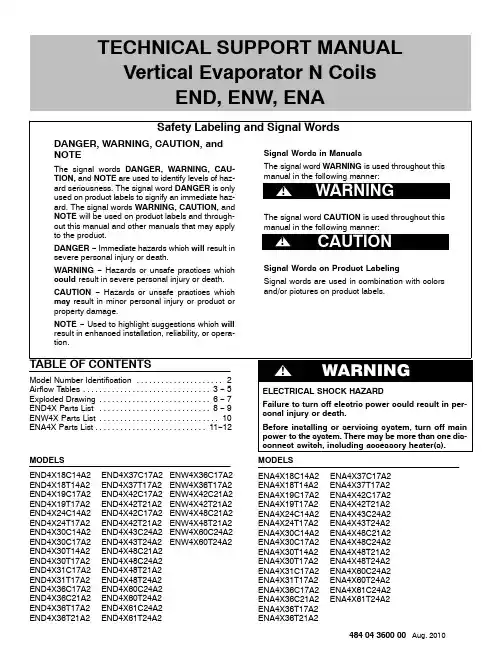
TECHNICAL SUPPORT MANUAL Vertical Evaporator N CoilsEND, ENW, ENAMODELSEND4X18C14A2END4X37C17A2ENW4X36C17A2 END4X18T14A2END4X37T17A2ENW4X36T17A2 END4X19C17A2END4X42C17A2ENW4X42C21A2 END4X19T17A2END4X42T21A2ENW4X42T21A2 END4X24C14A2END4X42C17A2ENW4X48C21A2 END4X24T17A2END4X42T21A2ENW4X48T21A2 END4X30C14A2END4X43C24A2ENW4X60C24A2 END4X30C17A2END4X43T24A2ENW4X60T24A2 END4X30T14A2END4X48C21A2END4X30T17A2END4X48C24A2END4X31C17A2END4X48T21A2END4X31T17A2END4X48T24A2END4X36C17A2END4X60C24A2END4X36C21A2END4X60T24A2END4X36T17A2END4X61C24A2END4X36T21A2END4X61T24A2MODELSENA4X18C14A2ENA4X37C17A2ENA4X18T14A2ENA4X37T17A2ENA4X19C17A2ENA4X42C17A2ENA4X19T17A2ENA4X42T21A2ENA4X24C14A2ENA4X43C24A2ENA4X24T17A2ENA4X43T24A2ENA4X30C14A2ENA4X48C21A2ENA4X30C17A2ENA4X48C24A2ENA4X30T14A2ENA4X48T21A2ENA4X30T17A2ENA4X48T24A2ENA4X31C17A2ENA4X60C24A2ENA4X31T17A2ENA4X60T24A2ENA4X36C17A2ENA4X61C24A2ENA4X36C21A2ENA4X61T24A2ENA4X36T17A2ENA4X36T21A2484 04 3600 00 Aug. 2010TECHNICAL SUPPORT MANUAL N Coils: END4X, ENW4X, ENA4X2484 04 3600 00COIL MODEL NUMBER IDENTIFICATION GUIDEDigit Position123456,789,101112E N D 4X 18C14A 1E = EvaporatorB = Builder D = Standard N = N Coil TYPE A = UncasedD = Cased Upflow/DownflowM = Cased Multiposition (Upflow/Downflow/Horizontal)W = Cased Upflow/Downflow for narrower furnaces H = Cased Horizontal INSTALLATION 4 = Environmentally Sound R −410A REFRIGERANT P = Piston X = TXVMETERING DEVICE18 = 18,000 BTUH = 1½ tons 19 = 18,000 BTUH = 1½ tons 24 = 24,000 BTUH = 2 tons 30 = 30,000 BTUH = 2½ tons 31 = 30,000 BTUH = 2½ tons 36 = 36,000 BTUH = 3 tons 37 = 36,000 BTUH = 3 tons 42 = 42,000 BTUH = 3½ tons 43 = 42,000 BTUH = 3½ tons 48 = 48,000 BTUH = 4 tons 60 = 60,000 BTUH = 5 tons 61 = 60,000 BTUH = 5 tons NOMINAL CAPACITYC = Plain CopperT = Tin Coated Copper HAIRPIN MATERIAL14 = 14−3/16”17 = 17−1/2”21 = 21”24 = 24−1/2”WIDTHSales Digit (Major Revision)Engineering Digit (Minor Revision)TECHNICAL SUPPORT MANUAL N Coils: END4X, ENW4X, ENA4XLegend:CFM− Cubic Ft. per Minute EWB− Entering Wet Bulb LWB− Leaving Wet Bulb TC− Gross Cooling Capacity 1000 Btuh SHC− Gross Sensible Capacity 1000 Btuh BF− Bypass Factor MBH− 1000 BtuhSee notes following.484 04 3600 003TECHNICAL SUPPORT MANUAL N Coils: END4X, ENW4X, ENA4X4484 04 3600 00CFM − Cubic Ft. per MinuteEWB − Entering Wet Bulb LWB − Leaving Wet Bulb TC − Gross Cooling Capacity 1000 BtuhSHC − Gross Sensible Capacity 1000 Btuh BF − Bypass FactorMBH − 1000 BtuhSee notes following.NOTES :1.Contact manufacturer for cooling capacities at conditions other than shown in table.2.Formulas:Leaving db = entering db − sensible heat cap.1.09 x CFMLeaving wb = wb corresponding to enthalpy of air leaving coil (h LWB )h LWB = h EWB − total capacity (Btuh)4.5 x CFMWhere h EWB = enthalpy of air entering coil3.SHC is based on 80°F (27°C) db temperature of air entering the evaporator coil.Below 80°F (27°C) db, subtract (Correction Factor x CFM) from SHC.Above 80°F (27°C) db, add (Correction Factor x CFM) to SHC.4.Direct interpolation is permissible. Do not extrapolate.5.Fan motor heat has not been deducted.6.All data points are based on 10°F (−12°C) superheat leaving coil and use of thermostatic expansion valve (TXV) device.7.The END4X, ENW4X, and ENA4X coils can be used in any properly designed system using R −410A refrigerant.8.Before using maximum cfm shown in table, check coil static pressure drop to ensure system blower can provide necessary static pressure needed for coil and duct systems.Correction Factor = 1.09 x (1 − BF) x (db − 80)TECHNICAL SUPPORT MANUAL N Coils: END4X, ENW4X, ENA4X* C= Plain Copper, T= Tin Coated Copper484 04 3600 005TECHNICAL SUPPORT MANUAL N Coils: END4X, ENW4X, ENA4XEND4X & ENW4X6484 04 3600 00TECHNICAL SUPPORT MANUAL N Coils: END4X, ENW4X, ENA4XENA4X484 04 3600 007TECHNICAL SUPPORT MANUALN Coils: END4X, ENW4X, ENA4X8484 04 3600 00END4X PARTS LISTKEY NO.DESCRIPTIONPART NO.E N D 4X 18C 14A 2E N D 4X 18T 14A 2E N D 4X 19C 17A 2E N D 4X 19T 17A 2E N D 4X 24C 14A 2E N D 4X 24C 17A 2E N D 4X 24T 14A 2E N D 4X 24T 17A 2E N D 4X 30C 14A 2E N D 4X 30C 17A 2E N D 4X 30T 14A 2E N D 4X 30T 17A 2E N D 4X 31C 17A 2E N D 4X 31T 17A 2E N D 4X 36C 17A 2E N D 4X 36C 21A 2E N D 4X 36T 17A 2E N D 4X 36T 21A 21COIL ASY EVAP 11831821−−−−−−−−−−−−−−−−−1COIL ASY EVAP 1183183−−−−1−−−−−−−−−−−−−1COIL ASY EVAP 1183184−−−−−1−−−−−−−−−−−−1COIL ASY EVAP 1183185−−−−−−−−1−−−−−−−−−1COIL ASY EVAP 1183186−−−−−−−−−1−−−−−−−−1COIL ASY EVAP 1183187−−−−−−−−−−−−−−1−−−1COIL ASY EVAP1183188−−−−−−−−−−−−−−−1−−1COIL ASY EVAP TINNED 1183224−1−−−−−−−−−−−−−−−−1COIL ASY EVAP TINNED 1183225−−−−−−1−−−−−−−−−−−1COIL ASY EVAP TINNED 1183226−−−−−−−1−−−−−−−−−−1COIL ASY EVAP TINNED 1183227−−−−−−−−−−1−−−−−−−1COIL ASY EVAP TINNED 1183228−−−−−−−−−−−1−−−−−−1COIL ASY EVAP TINNED 1183229−−−−−−−−−−−−−−−−1−1COIL ASY EVAP TINNED 1183230−−−−−−−−−−−−−−−−−11COIL ASY EVAP TINNED 1183305−−−1−−−−−−−−−−−−−−1COIL ASY EVAP TINNED 1183306−−−−−−−−−−−−−1−−−−3DISTRIBUTOR 118324*********−−−−−−−−−−3DISTRIBUTOR 1183250−−−−−−−−11111111114TXV 2.0 TON1176875−−11−−−−−−−−−−−−−−4VALVE TXV 3.0 TON R −410A 1183193−−−−−−−−111111−−−−4VALVE TXV 3.0 TON R −410A 118319411−−1111−−−−−−−−−−4VALVE TXV 4.0 TON R −410A 1183195−−−−−−−−−−−−−−11116DISTRIBUTOR ASY 118320*********−−−−−−−−−−6DISTRIBUTOR ASY 1183203−−−−−−−−11111111117CNDS PAN ASSY 118360811−−1−1−1−1−−−−−−−7CNDS PAN ASSY 1183609−−11−1−1−1−1111−1−7CNDS PAN ASSY 1183610−−−−−−−−−−−−−−−1−18STRAINER 1171740111111111111111111A SHIELD1173364111111111111111111B EXTENSION COIL 118321611−−−−−−−−−−−−−−−−B EXTENSION COIL 1183217−−−−1111−−−−−−−−−−B EXTENSION COIL 1183218−−11−−−−1111−−1111B EXTENSION COIL 1183220−−−−−−−−−−−−11−−−−C EXT CNDS PAN 1183222−−11−1−1−1−1111111C EXT CNDS PAN 118322311−−1−1−1−1−−−−−−−D SHIELD1176827111111111111111111E SHIELD LEFT/CENTER COIL 1173367111111111111111111F SHIELD RIGHT COIL 1173368111111111111111111G COVER ASY 118333611−−−−−−−−−−−−−−−−G COVER ASY 1183337−−11−−−−−1−1−−1−1−G COVER ASY 1183338−−−−1−1−−−−−−−−−−−G COVER ASY 1183339−−−−−1−1−−−−−−−−−−G COVER ASY 1183340−−−−−−−−1−1−−−−−−−G COVER ASY 1183341−−−−−−−−−−−−11−−−−G COVER ASY1183343−−−−−−−−−−−−−−−1−1K COVER ASY ACCESS 118332211−−−−−−−−−−−−−−−−K COVER ASY ACCESS 1183323−−11−−−−−1−1−−1−1−K COVER ASY ACCESS 1183324−−−−1−1−−−−−−−−−−−K COVER ASY ACCESS 1183325−−−−−1−1−−−−−−−−−−K COVER ASY ACCESS 1183326−−−−−−−−1−1−−−−−−−K COVER ASY ACCESS 1183327−−−−−−−−−−−−11−−−−K COVER ASY ACCESS1183329−−−−−−−−−−−−−−−1−1M GROMMET SUCT LINE 3/4”1173159−−11−−−−1111111111M GROMMET SUCT LINE 5/8”117315811−−1111−−−−−−−−−−N GROMMET LIQ LINE 3/8”1173157111111*********111TECHNICAL SUPPORT MANUALN Coils: END4X, ENW4X, ENA4X484 04 3600 009END4X PARTS LIST (continued)KEY NO.DESCRIPTIONPART NO.E N D 4X 37C 17A 2E N D 4X 37T 17A 2E N D 4X 42C 17A 2E N D 4X 42C 21A 2E N D 4X 42T 17A 2E N D 4X 42T 21A 2E N D 4X 43C 24A 2E N D 4X 43T 24A 2E N D 4X 48C 21A 2E N D 4X 48C 24A 2E N D 4X 48T 21A 2E N D 4X 48T 24A 2E N D 4X 60C 24A 2E N D 4X 60T 24A 2E N D 4X 61C 24A 2E N D 4X 61T 24A 21COIL ASY EVAP 1183189−−−1−−−−−−−−−−−−1COIL ASY EVAP 1183190−−−−−−−−1−−−−−−−1COIL ASY EVAP 1183191−−−−−−−−−1−−−−−−1COIL ASY EVAP1183192−−−−−−−−−−−−1−−−1COIL ASY EVAP TINNED 1183231−−−−−1−−−−−−−−−−1COIL ASY EVAP TINNED 1183232−−−−−−−−−−1−−−−−1COIL ASY EVAP TINNED 1183233−−−−−−−−−−−1−−−−1COIL ASY EVAP TINNED 1183234−−−−−−−−−−−−−1−−1COIL ASY EVAP TINNED 1183304−−−−−−−−−−−−−−−11COIL ASY EVAP TINNED 1183307−1−−−−−−−−−−−−−−1COIL ASY EVAP TINNED 1183308−−−−−−−1−−−−−−−−1COIL ASY EVAP TINNED 1183369−−−−1−−−−−−−−−−−3DISTRIBUTOR 1183250111111111111−−−−3DISTRIBUTOR1183251−−−−−−−−−−−−11114VALVE TXV 4.0 TON R −410A 118319*********−−−−−−−−4VALVE TXV 6 TON R −410A 1183196−−−−−−−−111111−−4VALVE TXV 6.0 TON R −410A 1183293−−−−−−−−−−−−−−116DISTRIBUTOR ASY 1183200−−1111111111−−−−6DISTRIBUTOR ASY 1183202−−−−−−−−−−−−11−−6DISTRIBUTOR ASY 118320311−−−−−−−−−−−−−−6DISTRIBUTOR ASY 1183294−−−−−−−−−−−−−−117CNDS PAN ASSY 1183609111−1−−−−−−−−−−−7CNDS PAN ASSY 1183610−−−1−1−−1−1−−−−−7CNDS PAN ASSY 1183611−−−−−−11−1−111118STRAINER 11717401111111111111111A SHIELD11733641111111111111111B EXTENSION COIL 1183219−−−1−1−−−−−−−−−−B EXTENSION COIL 1183220−−−−−−−−1111−−−−B EXTENSION COIL 118322111−−−−11−−−−11−−B EXTENSION COIL 1183295−−−−−−−−−−−−−−11B EXTENSION REAR 1183350−−1−1−−−−−−−−−−−C EXT CNDS PAN 11832221111111111111111D SHIELD11768271111111111111111E SHIELD LEFT/CENTER COIL 11733671111111111111111F SHIELD RIGHT COIL 1173368−−11111111111111F SHIELD118329611−−−−−−−−−−−−−−G COVER ASY 118334211−−−−−−−−−−−−−−G COVER ASY 1183344−−1−1−−−−−−−−−−−G COVER ASY 1183345−−−1−1−−−−−−−−−−G COVER ASY 1183346−−−−−−11−−−−11−−G COVER ASY 1183347−−−−−−−−1−1−−−−−G COVER ASY 1183348−−−−−−−−−1−1−−−−G COVER ASY1183349−−−−−−−−−−−−−−11K COVER ASY ACCESS 118332811−−−−−−−−−−−−−−K COVER ASY ACCESS 1183330−−1−1−−−−−−−−−−−K COVER ASY ACCESS 1183331−−−1−1−−−−−−−−−−K COVER ASY ACCESS 1183332−−−−−−11−−−−11−−K COVER ASY ACCESS 1183333−−−−−−−−1−1−−−−−K COVER ASY ACCESS 1183334−−−−−−−−−1−1−−−−K COVER ASY ACCESS1183335−−−−−−−−−−−−−−11M GROMMET SUCT LINE 3/4”1173159−−1111−−−−−−−−−−M GROMMET SUCT LINE 7/8”117316011−−−−1111111111N GROMMET LIQ LINE 3/8”11731571111111111111111TECHNICAL SUPPORT MANUALN Coils: END4X, ENW4X, ENA4X10484 04 3600 00ENW4X PARTS LISTKEY NO.DESCRIPTIONPART NO.E N W 4X 36C 17A 2E N W 4X 36T 17A 2E N W 4X 42C 21A 2E N W 4X 42T 21A 2E N W 4X 48C 21A 2E N W 4X 48T 21A 2E N W 4X 60C 24A 2E N W 4X 60T 24A 21COIL ASY EVAP 11831871−−−−−−−1COIL ASY EVAP 1183189−−1−−−−−1COIL ASY EVAP 1183190−−−−1−−−1COIL ASY EVAP1183192−−−−−−1−1COIL ASY EVAP TINNED 1183229−1−−−−−−1COIL ASY EVAP TINNED 1183231−−−1−−−−1COIL ASY EVAP TINNED 1183232−−−−−1−−1COIL ASY EVAP TINNED 1183234−−−−−−−13DISTRIBUTOR1183250111111113DISTRIBUTOR ASY 1183200−−1111−−3DISTRIBUTOR ASY 1183202−−−−−−113DISTRIBUTOR ASY118320311−−−−−−4VALVE TXV 4.0 TON R −410A 11831951111−−−−4VALVE TXV 6 TON R −410A 1183196−−−−11117CNDS PAN ASSY 118360911−−−−−−7CNDS PAN ASSY 1183610−−1111−−7CNDS PAN ASSY 1183611−−−−−−118STRAINER117174*********B EXT CNDS PAN 118322*********B EXTENSION COIL 118321811−−−−−−B EXTENSION COIL 1183219−−11−−−−B EXTENSION COIL 1183220−−−−11−−B EXTENSION COIL 1183221−−−−−−11D SHIELD 117336*********D SHIELD117682*********E SHIELD LEFT/CENTER COIL 117336*********F SHIELD RIGHT COIL 117336*********G COVER ASY 118333711−−−−−−G COVER ASY 1183345−−11−−−−G COVER ASY 1183346−−−−−−11G COVER ASY1183347−−−−11−−K COVER ASY ACCESS 118332311−−−−−−K COVER ASY ACCESS 1183331−−11−−−−K COVER ASY ACCESS 1183332−−−−−−11K COVER ASY ACCESS1183333−−−−11−−M GROMMET SUCT LINE 3/4”11731591111−−−−M GROMMET SUCT LINE 7/8”1173160−−−−1111NGROMMET LIQ LINE 3/8”117315711111111TECHNICAL SUPPORT MANUALN Coils: END4X, ENW4X, ENA4X484 04 3600 0011ENA4X PARTS LISTKEY NO.DESCRIPTIONPART NO.E N A 4X 18C 14A 2E N A 4X 18T 14A 2E N A 4X 19C 17A 2E N A 4X 19T 17A 2E N A 4X 24C 14A 2E N A 4X 24C 17A 2E N A 4X 24T 14A 2E N A 4X 24T 17A 2E N A 4X 30C 14A 2E N A 4X 30C 17A 2E N A 4X 30T 14A 2E N A 4X 30T 17A 2E N A 4X 31C 17A 2E N A 4X 31T 17A 2E N A 4X 36C 17A 2E N A 4X 36C 21A 21COIL ASY EVAP 11831821−−−−−−−−−−−−−−−1COIL ASY EVAP 1183183−−−−1−−−−−−−−−−−1COIL ASY EVAP 1183184−−−−−1−−−−−−−−−−1COIL ASY EVAP 1183185−−−−−−−−1−−−−−−−1COIL ASY EVAP 1183186−−−−−−−−−1−−−−−−1COIL ASY EVAP 1183187−−−−−−−−−−−−−−1−1COIL ASY EVAP 1183188−−−−−−−−−−−−−−−11COIL ASY EVAP TINNED 1183224−1−−−−−−−−−−−−−−1COIL ASY EVAP TINNED 1183225−−−−−−1−−−−−−−−−1COIL ASY EVAP TINNED 1183226−−−−−−−1−−−−−−−−1COIL ASY EVAP TINNED 1183227−−−−−−−−−−1−−−−−1COIL ASY EVAP TINNED 1183228−−−−−−−−−−−1−−−−1COIL ASY EVAP TINNED 1183305−−−1−−−−−−−−−−−−1COIL ASY EVAP TINNED 1183306−−−−−−−−−−−−−1−−4TXV 2.0 TON 1176875−−11−−−−−−−−−−−−4VALVE TXV 3.0 TON R −410A 1183193−−−−−−−−111111−−4VALVE TXV 3.0 TON R −410A 118319411−−1111−−−−−−−−4VALVE TXV 4.0 TON R −410A 1183195−−−−−−−−−−−−−−116DISTRIBUTOR 118324*********−−−−−−−−6DISTRIBUTOR 1183250−−−−−−−−111111116DISTRIBUTOR ASY 118320*********−−−−−−−−6DISTRIBUTOR ASY 1183203−−−−−−−−111111117CNDS PAN ASSY 118360811−−1−1−1−1−−−−−7CNDS PAN ASSY 1183609−−11−1−1−1−1111−7CNDS PAN ASSY 1183610−−−−−−−−−−−−−−−18STRAINER 11717401111111111111111A SHIELD 11733642222222222222222B EXTENSION COIL 118321611−−−−−−−−−−−−−−B EXTENSION COIL 1183217−−−−1111−−−−−−−−B EXTENSION COIL 1183218−−11−−−−1111−−11B EXTENSION COIL 1183220−−−−−−−−−−−−11−−C EXT CNDS PAN 1183222−−11−1−1−1−11111C EXT CNDS PAN 118322311−−1−1−1−1−−−−−E SHIELD LEFT/CENTER COIL 11733671111111111111111F SHIELD RIGHT COIL 11733681111111111111111G ENCLOSURE COIL 1173381−−−−−−−−−1−1−−1−G ENCLOSURE COIL 118320711−−−−−−−−−−−−−−G ENCLOSURE COIL 1183208−−−−1−1−−−−−−−−−G ENCLOSURE COIL 1183210−−−−−−−−1−1−−−−−G ENCLOSURE COIL 1183213−−−−−1−1−−−−−−−−G ENCLOSURE COIL 1183214−−−−−−−−−−−−−−−1G ENCLOSURE COIL 1183297−−11−−−−−−−−−−−−G ENCLOSURE COIL 1183298−−−−−−−−−−−−11−−PARTS NOT SHOWN)(ADAPTER DRN MALE LA 10850101111111111111111)(GROMMET LIQ LINE 3/8”11731571111111111111111)(GROMMET SUCT LINE 3/4”1173159−−11−−−−11111111)(GROMMET SUCT LINE 5/8”117315811−−1111−−−−−−−−)(WASHER TEFLON11740121111111111111111TECHNICAL SUPPORT MANUALN Coils: END4X, ENW4X, ENA4X12484 04 3600 00ENA4X PARTS LISTKEY NO.DESCRIPTIONPART NO.E N A 4X 36T 17A 2E N A 4X 36T 21A 2E N A 4X 37C 17A 2E N A 4X 37T 17A 2E N A 4X 42C 21A 2E N A 4X 42T 21A 2E N A 4X 43C 24A 2E N A 4X 43T 24A 2E N A 4X 48C 21A 2E N A 4X 48C 24A 2E N A 4X 48T 21A 2E N A 4X 48T 24A 2E N A 4X 60C 24A 2E N A 4X 60T 24A 2E N A 4X 61C 24A 2E N A 4X 61T 24A 21COIL ASY EVAP 1183189−−−−1−−−−−−−−−−−1COIL ASY EVAP 1183190−−−−−−−−1−−−−−−−1COIL ASY EVAP 1183191−−−−−−−−−1−−−−−−1COIL ASY EVAP 1183192−−−−−−−−−−−−1−−−1COIL ASY EVAP TINNED 11832291−−−−−−−−−−−−−−−1COIL ASY EVAP TINNED 1183230−1−−−−−−−−−−−−−−1COIL ASY EVAP TINNED 1183231−−−−−1−−−−−−−−−−1COIL ASY EVAP TINNED 1183232−−−−−−−−−−1−−−−−1COIL ASY EVAP TINNED 1183233−−−−−−−−−−−1−−−−1COIL ASY EVAP TINNED 1183234−−−−−−−−−−−−−1−−1COIL ASY EVAP TINNED 1183304−−−−−−−−−−−−−−−11COIL ASY EVAP TINNED 1183307−−−1−−−−−−−−−−−−1COIL ASY EVAP TINNED 1183308−−−−−−−1−−−−−−−−3DISTRIBUTOR 1183250111111111111−−−−3DISTRIBUTOR 1183251−−−−−−−−−−−−11113DISTRIBUTOR ASY 1183200−−1111111111−−−−3DISTRIBUTOR ASY 1183202−−−−−−−−−−−−11−−3DISTRIBUTOR ASY 118320311−−−−−−−−−−−−−−3DISTRIBUTOR ASY 1183294−−−−−−−−−−−−−−114VALVE TXV 4.0 TON R −410A 118319*********−−−−−−−−4VALVE TXV 6 TON R −410A 1183196−−−−−−−−111111−−4VALVE TXV 6.0 TON R −410A 1183293−−−−−−−−−−−−−−117CNDS PAN ASSY 11836091−11−−−−−−−−−−−−7CNDS PAN ASSY 1183610−1−−11−−1−1−−−−−7CNDS PAN ASSY 1183611−−−−−−11−1−111118STRAINER 11717401111111111111111A SHIELD 11733642222222222222222A SHIELD 1183296−−11−−−−−−−−−−−−B EXTENSION COIL 118321811−−−−−−−−−−−−−−B EXTENSION COIL 1183219−−−−11−−−−−−−−−−B EXTENSION COIL 1183220−−−−−−−−1111−−−−B EXTENSION COIL 1183221−−11−−11−−−−11−−B EXTENSION COIL 1183295−−−−−−−−−−−−−−11C EXT CNDS PAN 11832221111111111111111E SHIELD LEFT/CENTER COIL 11733671111111111111111F SHIELD RIGHT COIL 117336811−−111111111111G ENCLOSURE COIL 11733811−−−−−−−−−−−−−−−G ENCLOSURE COIL 1183209−−−−11−−−−−−−−−−G ENCLOSURE COIL 1183211−−−−−−−−1−1−−−−−G ENCLOSURE COIL 1183212−−−−−−−−−−−−11−−G ENCLOSURE COIL 1183214−1−−−−−−−−−−−−−−G ENCLOSURE COIL 1183215−−−−−−−−−1−1−−−−G ENCLOSURE COIL 1183299−−−−−−11−−−−−−−−G ENCLOSURE COIL 1183300−−11−−−−−−−−−−−−G ENCLOSURE COIL 1183301−−−−−−−−−−−−−−11PARTS NOT SHOWN)(ADAPTER DRN MALE LA 10850101111111111111111)(GROMMET LIQ LINE 3/8”11731571111111111111111)(GROMMET SUCT LINE 3/4”1173159111111−−−−−−−−−−)(GROMMET SUCT LINE 7/8”1173160−−−−−−1111111111)(WASHER TEFLON11740121111111111111111International Comfort Products, LLCLewisburg, T ennessee 37091。
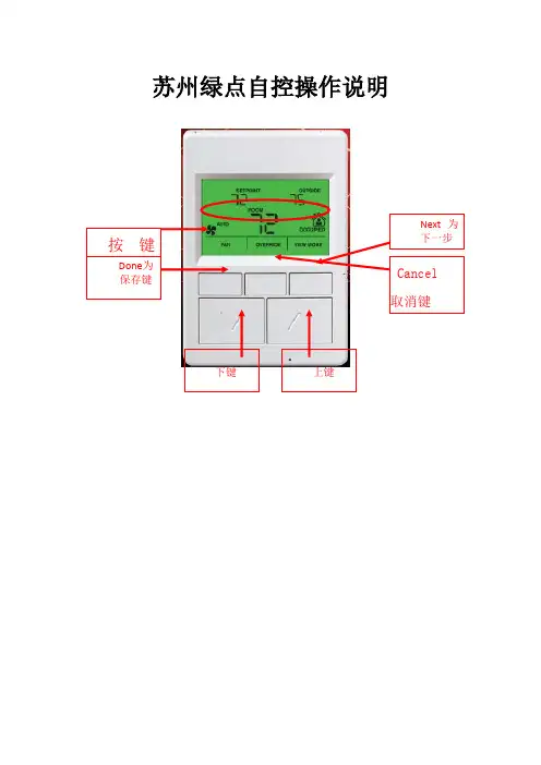
苏州绿点自控操作说明•面板对照表第一种类型UI1 MAU-201出风温度UI2 MAU-202出风温度UI5 MAU-201风车压差AO1 MAU-201冰水阀开度AO2 MAU-202冰水阀开度DI3 MAU-202风车压差Wsp_t1 MAU-201出风温度设定Wsp_t2 MAU-202出风温度设定Qh 冬夏切换第二种类型UI2 AHU-201回风温度UI3 2F末端水管压力AO1 AHU-201冰水阀开度AO2 AHU-201新风风门DI3 AHU-201风车压差DI4 AHU-201滤网压差Wsp_t1 AHU-201回风温度设定Qh 冬夏切换TR71面板操作说明面板显示点与接线表相对应例如:UI1:出风温度DI3:风车压差AO1:冰水阀开度AO1_DIS:冰水阀开度显示AO1_AM:与上述对应的手自动切换,“0”为自动,“1”为手动AO1_IN:与上述对应手动强制输入点Wsp_t1:出风温度设定值,可任意修改所需值以下为面板操作步骤:上述为主界面,按右边第一位,就可以进入显示屏上分3段,刚好底下有3个按键与此对应,从左到右依次为DONE,CANCEL,NEXT(确定,取消,下一步)按住NEXT,就可以看到这台控制器里面所有的点上述为UI1,继续点击NEXT,就能看到所有UI点对应的数据。
上述为DI1,显示风车的状态,故障和压差等,显示数值为“0”和“1”,“0”代表运行和正常,“1”代表停止与故障。
上述为阀体的开度显示点,AO1_DIS为蒸汽阀的开度显示上述为AO1冰水阀的手自动切换点,“0”代表蒸汽阀受程序自动控制,按照设计好的程序进行;“1”代表蒸汽阀不受程序控制,根据手动输入的值进行。
即“1”代表手动,“0”代表自动。
按面板上的上下键,就能修改数值。
上述为当AO1为手动强制输入之后的,AO1的强制输出值,通过上下键修改数值,之后按左上角的DONE键确认。
(0~100对应0~10V)上述为水泵和阀体的启停点,“0”代表停止,“1”代表启动。

HoneywellDC1000系列通用调节器简要说明书(中文版)注意:使用本手册前,请检查量程,输入,输出是否符合您的要求.1.面板说明1.1显示说明PV: 过程值(process value),四位显示(红色)SP: 设定值(set point),四位显示(绿色)1.2LED指示灯说明OUT1: 第一路输出(OUTPUT1), 绿色灯OUT2: 第二路输出(OUTPUT2), 绿色灯AT: 自整定,黄色灯PRO: 程序运行中,黄色灯AL1: 第一路报警(ALARM 1),红色灯AL2: 第二路报警(ALARM 1),红色灯AL3: 第三路报警(ALARM 1),红色灯 (DC1010无此功能)MAN: 手动控制,黄色灯 (DC1010无此功能)1.3 按键SET: 模式&设定键(切换模式和写入设定值)Y:移位键▽:减少键△:增加键A/M:自动/手动切换键2.自整定功能2.1 将AT设置为‘YES’,即启动自整定功能2.2 自整定完成后,PID参数将被自动设定。
(P值一般为11~14, I值一股为40~50, D值一般为40~60。
)2.3 ATVL=自整定偏移量,由SP值推导出来(它在自整定时,可防止振荡超过设定点)SP-ATVL=自整定设定值, ATVL=自整定偏移量例如: SP=200℃, ATL=5, 则自整定点是195℃*ATVL务必自整定点在程序类型模式中(195℃)2.4 自整定点失败2.4.1 ATVL值太大→如果不能确定,则设定ATVL=02.4.2系统时间太长→单独设定PID参数3. 故障信息(注意)当有“*”标记的故障发生时,控制器需要维修4.操作流程各阶层进出及参数的锁定4.1.1按移位键(Y)改变参数。
按下移位键,第一位数开始闪烁。
按增加键(△)或减少键(▽)对此数值作增加或减少,再按移位键到第二位数,当所有数值设定好后,按SET键完成数值设定。
4.1.2SET键也有转换模式的功能,按下SET键会显示下一种模式4.1.3按SET键持续5秒可进入LEVEL2,或同样可返回LEVEL1。
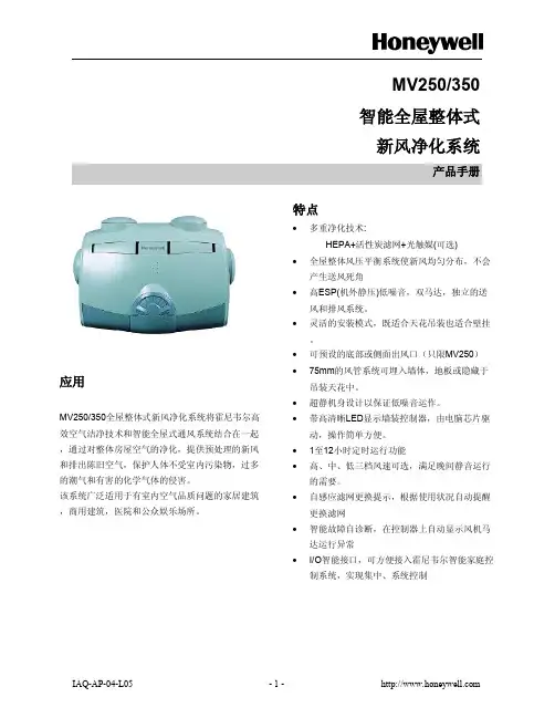
MV250/350智能全屋整体式新风净化系统产品手册应用MV250/350全屋整体式新风净化系统将霍尼韦尔高效空气洁净技术和智能全屋式通风系统结合在一起,通过对整体房屋空气的净化,提供预处理的新风和排出陈旧空气,保护人体不受室内污染物,过多的潮气和有害的化学气体的侵害。
该系统广泛适用于有室内空气品质问题的家居建筑,商用建筑,医院和公众娱乐场所。
特点·多重净化技术:HEPA+活性炭滤网+光触媒(可选)·全屋整体风压平衡系统使新风均匀分布,不会产生送风死角·高ESP(机外静压)低噪音,双马达,独立的送风和排风系统。
·灵活的安装模式,既适合天花吊装也适合壁挂。
·可预设的底部或侧面出风口(只限MV250)·75mm的风管系统可埋入墙体,地板或隐藏于吊装天花中。
·超静机身设计以保证低噪音运作。
·带高清晰LED显示墙装控制器,由电脑芯片驱动,操作简单方便。
·1至12小时定时运行功能·高、中、低三档风速可选,满足晚间静音运行的需要。
·自感应滤网更换提示,根据使用状况自动提醒更换滤网·智能故障自诊断,在控制器上自动显示风机马达运行异常·I/O智能接口,可方便接入霍尼韦尔智能家庭控制系统,实现集中、系统控制产品规格重要须知于此规格书中所显示之产品规格,并不包含一般制造公差,故实际产品可能不完全与所列规格一致。
而且,本产品是在严格受控环境之下测试及测定,如果环境条件有所改变,在性能表现上会有微小的差异。
电源:220Vac/50Hz型号最大功耗(W)风速处理风量(CMH)噪音dB(A)MV250153高25052.5中20049.5低16043.5MV350276高35055.5中29052.5低21046.5性能曲线:参看图1,2尺寸:参看图3包装尺寸:545x300x410mm 安装重量:8.6KG 运输重量:10.5KG 过滤器:HEPA+活性炭环境要求:储藏和运输0-350C 运行-15-500C安装模式:天花悬吊或壁挂连接所用管道:(建议B2 Class UPVC 管)主管:89mm 支管:75mm图 2. MV350 性能曲线图图 1. MV250 性能曲线图计划安装应用:本新风净化系统是设计用于净化室外的新鲜空气并以此取代室内的混浊空气。
霍尼韦尔MCT多协议通讯器 MCT202手操器Honeywell MCT 多协议通讯器(基本型和本安型)概述霍尼韦尔公司 MCT 通讯器是一种基于掌上电脑的工程和维护工具,可用于对现场智能设备和仪表的组态、监测、诊断和管理。
遵循易于使用和提高生产率的准则而设计,这款多协议通讯器可以支持 HART协议和霍尼韦尔数据增强型(DE)协议。
该 MCT 通讯器可以容易地对设备的数据参数进行组态,而无需预先培训、用户手册或使用经验。
每台MCT通讯器都预装了所有已登记的 HART 设备文件(DD),而且可以随时补充未公开的 DD 文件——只需下载新的HART 设备的 DD 文件,即可进行组态。
使用 ActiveSync 软件和 USB 电缆,可以很容易地下载新的 DD文件。
特性•可对霍尼韦尔的所有DE 设备组态,包括ST3000 系列变送器和 STT3000 温度变送器•可对所有数据公开的 HART 设备组态,而不必考虑其生产厂家。
•可以很容易地通过 PC 下载任何新的供货厂家的 DD 文件。
•简单的用户图形界面,对设备组态很容易。
•可以提供3种规格,满足任何环境要求“•环境没有防爆要求。
•Zone 2 型:本安认证 FM Class I, Div 2 和 ATEX Zone 2。
•Zone 1 型:本安认证 FM Class I, Div 1 和 ATEX Zone 1。
•完全支持所有 HART 5.X 和 HART 6.X 指令,采用DD-IDE / SDC 625 技术和“开放”的工具标准。
说明•可对变送器进行诊断、在线监视以及组态。
•一个手持终端就可以对HART和DE设备组态,支持所有通用的、普通的和专用的组态指令。
•组态过程中用户界面提供详细的解释和子菜单,即使对新手也很容易使用。
•当操作员使用以下功能时,支持与 HART 设备的通讯:•设备初始组态。
•启动方式。
•改变组态参数。
•确定实际的状态或特定设备过程参数。

HMR3200/HMR3300型数字罗盘用户手册目录概述 (3)规格性能参数 (3)插脚配置 (4)电路说明 (4)结构参数 (5)应用说明 (6)UART通讯协议 (6)运行命令 (6)设置命令 (7)磁场滤波器 (8)响应命令 (8)数字表示 (9)SPI时间设定 (9)电路板模块演示套件 (10)通讯开发套件 (10)开发套件安装 (10)HMR3200型演示程序的操作 (11)HMR3300型演示程序的操作 (11)简介霍尼韦尔HMR3200/HMR3300型数字罗盘是一种电子式罗盘装置,主要用于航海和导航系统,霍尼韦尔磁阻传感器为这些小型的固态电子罗盘装置提供了足够的可靠性和精确性,这类罗盘装置很容易在系统中集成,只需要使用ASCII格式的UART或者SPI 协议就可以方便地实现。
HMR3200型数字罗盘是双轴式罗盘,既可以用于垂直方向的探测,也可以用于水平方向的探测。
HMR3300型数字罗盘是三轴式罗盘,属于可以倾斜补偿的罗盘,由于使用了双轴式加速度计,性能得到了极大的提高,倾斜角度可以达到±60°。
技术规格参数适用条件最小值标准值最大值单位航向精度水平0°至±30°(仅HMR3300)±30°至±60°(仅HMR3300) 1.03.04.0RMS 度(°)分辨率 0.1 度(°)磁滞性HMR3200HMR3300 0.10.20.20.4度(°)重复性HMR3200HMR3300 0.10.20.20.4度(°)纵倾与侧倾(仅HMR3300)范围纵倾与侧倾范围 ±60° 度(°)精度0至±30°±30°至±60° 0.41.00.51.2度(°)零位精度水平-20°至+70°热磁滞性能-40°至+85°热磁滞性能 0.41.0度(°)分辨率 0.1 度磁滞性 0.2 度重复性 0.2 度磁场范围最大磁通量 ±2 高斯分辨率 0.1 毫高斯电场输入电压未调制 6 15 直流电压电流HMR3200HMR3300 18222024mAmA参数适用条件最小值标准值最大值单位数字接口UART协议 ASCII(1启动、8数字、1停止、无奇偶校验)用户可以选择波特率2400 19200波特SPI CKE=0, CKP=0虚拟主通道更新速率连续/选通/平均HMR3200 HMR3300 158Hz连接器在线8插脚模块(间距0.1”)物理量外形尺寸电路板组件 25.4×36.8×11mm重量HMR3200HMR3300 7.257.5g环境温度工作温度(HMR3200)工作温度(HMR3300)储存温度-40-20-55---+85+70+125°C插脚配置插脚编号插脚名称描述1 SCKSPI 模式串行时钟输出2 RX/SDIUART 接收数据/SPI 数据输入3 TX/SDOUART 发送数据/SPI 数据输出4 CSSPI模式(输入)时选用跟踪侧模块5 CAL开关触发(输入)跟踪侧校正6 +5VDC*备选的+5VDC 电源(输入)7 接地电源和信号接地8 +V*未稳压的电源输入(+6 到+15VDC)*注:电路板可以用插脚6(+5VDC)或插脚8(+V)接口供电,手持模块时将插脚侧靠近自己,并将插脚朝下,则最左边为插脚1。

TECHNICAL REFERENCE MANUAL31-00160-01BuildingEKM-E Ether-Mon Key DE-211INSTALLATION AND SETUP GUIDETABLE OF CONTENTSIntroduction .............................................................................................................................................2 Features .............................................................................................................................................2 Product Specifications .............................................................................................................................................2 Package Checklist .............................................................................................................................................3 LED Indicators .............................................................................................................................................5 Wall Mount .............................................................................................................................................5 DIP Switch Pre and Post Configuration .........................................................................................................................................7 Ethernet Configuration .............................................................................................................................................8 Installing the Moxa software “NPort Utility” ................................................................................................................................9Connecting the E10039 to a PC .............................................................................................................................................13 EZ7 RS485 Wiring Typical Installation ...........................................................................................................................................29Correct Daisy Chain Configuration ................................................................................292-Wire RS-485 Terminal Block Wiring ..........................................................................31EZ7 RS485 Wiring .. (32)Typical Cable Part Numbers (33)Enabling Termination Resistor ........................................................................................34Honeywell E-Mon Recommends Enabling the Built-In 120 Ω Terminator . (34)Compliance Notice (34)EKM-E ETHER-MON KEY DE-211INTRODUCTIONHoneywell E-Mon E10039 / NPort Express DE-211 provides a data communications solution for connecting Windows to asynchronous serial devices over a TCP/IP Ethernet. You may connect your Windows host to a native RS-485 serial port, through TCP/IP Ethernet. With one asynchronous serial port connection on one end, and a 10 Mbps Ethernet connection on the other, E10039 NPort Express allows virtually any EZ7 serial device to attach to a network. NPort Express works like an add-on single-port serial board to your PC server, but with one major advantage—the TCP/IP network. Since the host communicates with the COM port on NPort Express over a TCP/IP network, you are able to control your asynchronous serial device from virtually any location.FEATURES•2-in-1 EZ7 RS-485 interface and 10 Mbps Ethernet•Supports 2-wire EZ7 RS-485 with patented ADDC™ and built-in terminator•Terminal block for easy RS-485 serial wiring•Supports MAC based IP configuration•Supports configuration store and copy for easy deployment•Supports Windows Real COM driver•Supports TCP Server•Supports TelnetPRODUCT SPECIFICATIONSInterface:LAN: 10BaseTSerial: EZ7 RS-485Number of Ports: 1Signals:EZ7 RS-485 2-wire: Data+/-, GNDSurge protection:15 KV ESD (RS-232), 12KV ESD (RS-485)Magnetic isolation:1.5 KV for EthernetRegulatory approvals:EMC: CE Class B, FCC Class BSafety:UL 60950-1, EN 60950-131-00160—012EKM-E ETHER-MON KEY DE-211PACKAGE CHECKLIST• 1 A/C 120 volt to 12 VDC Power Adapter 0.5 A• 1 E10039 (EKM-E) NPort Express DE-2111•NP21103 DB25 terminal block kit for RS-485 (Installed on E10039)•RJ-45 Patch Cable•Quick Installation Guide•Product Warranty Booklet•NPort Documentation & Software CDFig. 1.331-00160—01EKM-E ETHER-MON KEY DE-211Fig. 2. 31-00160—014EKM-E ETHER-MON KEY DE-211531-00160—01LED INDICATORSE10039 NPort Express’s top panel contains five LED indicators, as described in the following table.Table 1.WALL MOUNTFor many industrial applications, you will find it convenient to mount NPort Express on the wall, using two screws, as indicated below.1.Screw two screws, separated by 7.8cm, into the wall. The heads of the screws should be no greater than 6.5mm in diameter, and the shafts should be no greater than 3mm in diameter. Do no screw the screws in all the way. Leave a space of about 2mm to allow room for sliding the NPort Express unit’s ears between the wall and the screws.Fig. 3.LED Name LED ColorLED FunctionPWR Red Power is on.Off Power is off, or power error condition exists.Link Orange 10 Mbps Ethernet connection.Off Ethernet cable is disconnected, or has a short.ReadyGreen NPort Server systen us ready.BlinkingNPort is requesting an IP address from the DHCP or BootP server. After receiving the IP, the LED will stop blinking.← →Note: The LED will also blink when you press the reset button; see page 1-5 for details.OffNPort Server has malfunctioned.Serial Tx Green Serial data is being transmitted.Off Serial data is not being transmitted.Serial RxOrange Serial data is being received.OffSerial data is not being received.EKM-E ETHER-MON KEY DE-2112.Insert the two screw heads through the large parts of the keyhole shaped apertures, and then slide the NPortExpress downward, as indicated.Fig. 4.3.For added stability, simply tighten the two screws.Fig. 5.31-00160—016EKM-E ETHER-MON KEY DE-211731-00160—01DIP SWITCH PRE AND POST CONFIGURATIONIMPORTANT!Before powering up the E10039 turn all 4 dip switches to Off (down postion).Fig. 6.1.Plug the power supply in Ethernet Key. The Red PWR and Green Ready LED light should illuminate as shown below.Fig. 7.2.Turn the middle two dip switches switch 2 & 3 on in the (up position).EKM-E ETHER-MON KEY DE-211ETHERNET CONFIGURATION Default IP address 192.168.127.254MAC Address see the back of the caseFig. 8. 31-00160—018EKM-E ETHER-MON KEY DE-211INSTALLING THE MOXA SOFTWARE “NPORT UTILITY”You may use Telnet or install the Moxa software CD to configure the E10039 Static IP address and network settings as required for Honeywell E-MonEnergy software.Use the supplied Moxa software CD or download from the following link:/~/media/downloads/manuals/dssetup.ashx?la=enIf downloading from the web select “Save as” and save the file to you desktopFig. 9.Fig. 10.931-00160—01EKM-E ETHER-MON KEY DE-21131-00160—01101.Open or extract from the downloaded zip file “dssetup ”.Fig. 11.2.Open the software installer and click Run at this pop up window.Fig. 12.EKM-E ETHER-MON KEY DE-2111131-00160—013.Click Next >.Fig. 13.4.Select Configuration and Management Tools (deselect COM Port Mapping Tools).5.Click Next >.Fig. 14.EKM-E ETHER-MON KEY DE-21131-00160—01126.Click Next >.Fig. 15.7.Click Next >.Fig. 16.EKM-E ETHER-MON KEY DE-211 8.Close / Exit the Configurator software window when it appears.Fig. 17.CONNECTING THE E10039 TO A PC9.For this step, you will need a Cross-over Ethernet cable to connect your PC to the E10039. A Cross-over cable is not,the same as the Patch cable that came with the E10039 Ether-Mon key.More about Cross-over cables /wiki/Ethernet_crossover_cableYou may purchase pre-made Cross-over cables at an office supply or electronics stores.When configuring drivers and software, need to hook the E10039 NPort Express directly to your computer’s Ethernet card. To do this, you will need to use a cross-over Ethernet cable.This type of Ethernet cable is harder to find, although you can make your own cable by referring to the following cable wiring diagram.Fig. 18.1331-00160—01EKM-E ETHER-MON KEY DE-21110.Plug one end of the Cross-over cable into the LAN Ethernet port of your PC and the other end into the EthernetRJ-45 port of the E10039 Ether-Mon key.Fig. 19.11.The Orange Link LED should blink as it is acquiring the network and then light up solid.Fig. 20.31-00160—0114EKM-E ETHER-MON KEY DE-2111531-00160—0112.Open your PC Control Panel, click Network and Internet .Fig. 21.13.Click Network and Sharing Center .Fig. 22.EKM-E ETHER-MON KEY DE-21131-00160—011614.Click Change adapter settings (WIRED ONLY).Fig. 23.15.Double Click Local Area Connection .Fig. 24.EKM-E ETHER-MON KEY DE-2111731-00160—0116.Click Properties .Fig. 25.17.Click to highlight Internet Protocol Version 4 (TCP/IPv4).18.Click Properties .Fig. 26.EKM-E ETHER-MON KEY DE-21131-00160—011819.Select Use the following IP address .Fig. 27.20.Next you will temporarily set the IP address of your computer to be a number close to the default IP address of the EKM-E Ethernet Key.a.For example, set the computer IP address to: 192.168.127.253 (final digit is one number lower than defaultEKM-E IP address).Fig. 28.EKM-E ETHER-MON KEY DE-2111931-00160—01b.Clicking into the Subnet mask field will auto populate to 255.255.255.0.Fig. 29.c.Click OK and close any of the Internet Protocol Version 4 properties screens.21.Launch the NPort Management Suite Configurator software.Fig. 30.EKM-E ETHER-MON KEY DE-21131-00160—0120Fig. 31.22.Click → Locate Server → Specify by IP Address .Fig. 32.23.Type in the E10039 default IP address of 192.168.127.254 and click OK .Fig. 33.2131-00160—0124.Model DE-211 should auto populate the IP Address, MAC Address, and Status Fixed.Fig. 34.25.Note if the Status displays Locked, type in the password emon if prompted.Fig. 35.Fig. 36.31-00160—012226.Click → Configuration → Modify Configuration .Fig. 37.27.Click the boxes next to IP Address, Netmask, and Gateway to modify these for your LAN or WAN settings as provided by your Internet Service Provider (ISP) or Network Administrator.IMPORTANT!The IP configuration must a Static IP to communicate properly with Honeywell E-Mon Energy software.Fig. 38.28.Click on the OP_Mode tab.29.Check the box Change OP-Mode .2331-00160—0130.Select TCP Server from the dropdown menu.Fig. 39.31.Click More Settings .Fig. 40.31-00160—0124Fig. 41.32.Set up the TCP Server exactly as shown below. a.TCP Port 3000b.Check the box for Delimiter 1 and set to 13c.Check the box for Delimiter 2 and set to 10d.Force transmit time out set to 2000e.Inactivity time 0f.TCP alive check time to 5g.Click OKFig. 42.33.Click the Serial Settings tab and click to check the box for Change Serial Port Settings.Fig. 43.34.Set Serial Settings exactly as shown in the window above.a.Baud Rate 9600b.Parity Nonec.Data Bits 8d.Stop Bit 1e.Flow Control Nonef.UART FIFO Enable35.Click the Password tab.36.Select the box Change Password.37.Honeywell E-Mon recommends using emon (lower case) as the defalt password in the event technical supportrequires remote access to configure the E10039 settings.2531-00160—0131-00160—012638.Type in New Password emon (lower case).39.Confirm Password emon (lower case).Fig. 44.40.Click OK to save and upload all changes and settings.41.Set Configuration uploaded settings Progress OK indicates finished.Fig. 45.42.Close Configurator utility.2731-00160—0143.Open the Configurator utility to confirm IP address and Status is Locked Fixed.Fig. 46.Fig. 47.44.Be sure to change your PC back to its original settings for the Internet Protocol Version 4.Fig. 48.e the supplied patch cable to plug the E10039 EKM-E into a router or switch.46.Your Internet Service Provider (ISP) or Network Administrator is responsible for suppling routers or switches.47.Please note: your ISP or your Network Administrator must configure the router or switch with Port 3000 TCP open.NOTE:E-MonEnergy software requires Port No. 3000 as shown below.Fig. 49. IMPORTANT!Port 3000 TCP must be open on all routers or switches in the network.31-00160—01282931-00160—01EZ7 RS485 WIRING TYPICAL INSTALLATIONFig. 50.Daisy Chain configuration shown in figure 2 on the left is correct, Star connection on the right is incorrect.Fig. 51.Correct Daisy Chain ConfigurationFig. 52.Please see the specific product installation manual for more detailed EZ7 RS-485 wiring.Fig. 53.Fig. 54. Front View E10039.31-00160—0130Fig. 55. 5 Position Screw Terminal Block.2-Wire RS-485 Terminal Block WiringFig. 56.Terminal 1 SGND: Do not use the groundTerminal 2 RXDB (+) DATA B (+): to RS485 HI or +Terminal 3 RXDA (-) DATA A (-): to RS485 LO or -3131-00160—01EZ7 RS485 WiringHow many EZ7 RS485 devices may be installed on one network trunk?Up to 52 devices may be installed on a network string (EZ7 RS485 only) read with E-MonEnergy software.What wire gauge do you need?Unterminated networks with current less than 10mA; we recommend 20AWG to 22stranded twisted pair with a shield. How long can the cable be?Under ideal conditions and default baud rates of 9,600, cable lengths of 4,000feet (~1200meters) is possible. However, the cable recommended for long lengths can be expensive. So if there is an existing Ethernet infrastructure in place it may be more affordable to convert from EZ7 RS485 to EZ7 Ethernet. Please consult with your system integrator for communication device options.What should the cable impedance and capacitance be?Cables suitable for use in an RS-485 network should have an impedance of between 100 and 130ohms, a capacitance between conductors of less than 30 pF per foot (100 pF per meter), and a capacitance between conductors and shield less than 60pF per foot (200 pF per meter.)Can you run the RS-485 network cable adjacent to or in the same conduit with load bearing feeders?We strongly recommend against this. There may be interference from the high voltages and currents present on the mains wires, and if there is any insulation fault, arcing, etc. on the mains wires, it could put dangerous voltages on the low-voltage RS-485 network cable.31-00160—0132TYPICAL CABLE PART NUMBERSTable 2. Communication Cables.ProductCode Description CommunicationStandardCharacteristicImpedanceCapacitance(pF/ft.)Color Packaging Part Number331924/1pr StrandedShielded CMP EIA-485, MS/TP,BACnet®11512.5Orange1000’ Reel-in-a-Box33192103332324/1.5pr StrandedShielded CMP EIA-485, MS/TP,BACnet11512.5Natural1000’ Reel-in-a-Box33232112Orange1000’ Reel-in-a-Box33232103332022/1pr StrandedShielded CMP EIA-485, MS/TP,BACnet11512.5Orange1000’ Reel-in-a-Box33202103Green1000’ Reel-in-a-Box33202105Blue1000’ Reel-in-a-Box33202106332422/1.5pr StrandedShielded CMP EIA-485, MS/TP,BACnet11512.5Blue1000’ Reel-in-a-Box33242106332822/2pr StrandedShielded CMP EIA-485, MS/TP,BACnet11512.5Brown1000’ Reel-in-a-Box33282107332218/2pr StrandedShielded CMP EIA-485, MS/TP,BACnet11512.5Orange1000’ Reel33221003325222/1pr Stranded CMP Echelon LonWorks®10014.5White1000’ Reel-in-a-Box32522101Yellow1000’ Reel-in-a-Box32522102Blue1000’ Reel-in-a-Box32522106Purple1000’ Reel-in-a-Box32522110White withOrangeStripe1000’ Reel-in-a-Box3252213A325322/2pr Stranded CMP Echelon LonWorks10014.5White1000’ Reel-in-a-Box32532101Blue1000’ Reel-in-a-Box32532106325422/1pr StrandedShielded CMP Echelon LonWorks10014.5White1000’ Pull Box32541101Blue1000’ Reel-in-a-Box32542106325522/2pr StrandedShielded CMPEchelon LonWorks10014.5White1000’ Pull Box32551101465218/1pr StrandedShielded CMP6025.0Purple1000’ Reel-in-a-Box465221103331-00160—01Enabling Termination ResistorFor RS-485 EZ7 serial communications, when an electrical signal travels through two different resistance junctions in a transmission line, the impedance mismatch will sometimes cause signal reflection. Signal reflection causes signal distortion, which in turn will contribute to communication errors. The solution to this problem is to establish the same impedance at the line ends as in the line itself, by terminating them with resistors.The impedance of the termination resistor should equal the characteristic impedance of the transmission line. The resistors should be added near the receiving side.Honeywell E-Mon Recommends Enabling the Built-In 120 Ω Terminator To enable the E10039’s built-in 120 Ω termination resistor, you must short the bottom two pins of jumper 6 (JP6), on DE-211’s circuit board. To do this:e a screwdriver to remove DE-211’s outer protective case, and then locate JP6, as shown in the figures below.2.By default, the top two pins of JP6 are shorted, which means that the built-in 120 Ω termination resistor is disabled(completely removing the jumper from the pins also disables the resistor).e the jumper to short the bottom two pins of JP6 to enable the built-in 120 Ω termination resistor.Fig. 57.COMPLIANCE NOTICEFederal Communications Commission StatementFCC - This device complies with part 15 of the FCC Rules. Operation is subject to following two conditions: (1) This device may not cause harmful interference, and (2) This device must accept and interference received, including interference that may cause undesired operation.WARNINGFCC WarningThis equipment has been tested and found to comply with the limits for a Class A digital Device, pursuant to part15 of the FCC Rules. These limits are designed to provide reasonable protection against harmful interferencewhen the equipment is operated in a commercial environment. This equipment generates, uses, and can radiate radio frequency energy and, if not installed and used in accordance with the instruction manual, may causeharmful interference to radio communications. Operations of this equipment in a residential area is likely to causeharmful interference in which case the user will be required to correct the interference at this own expense.31-00160—01343531-00160—01Home and Building Technologies In the U.S.:Honeywell715 Peachtree Street NEAtlanta, GA 30308 ® U.S. Registered Trademark© 2018 Honeywell International Inc. 31-00160—01 M.S. 05-18Printed in United StatesBy using this Honeywell literature, you agree that Honeywell will have no liability for any damages arising out of your use or modification to, the literature. You will defend and indemnify Honeywell, its affiliates and subsidiaries, from and against any liability, cost, or damages, including attorneys’ fees, arising out of, or resulting from, any modification to the literature by you.。
产品特色• 高效率直流变频双电机• 初效 + 活性碳 +HEPA 三效过滤网• 主机侧面检修口,施工保养更便利• 长寿命的滚动轴承• 缓启动控制电路• 自动旁通 ( 配备机种 : VEB350AP )PM2.5 直流变频全热交换机安装及使用说明书VEB150AP VEB250AP VEB350AP• 请于安装、使用及维修本产品前,详细阅读本说明书。
• 不遵照此说明书进行操作,有可能导致人员受伤或财产损失。
• 为确保您的权益,务必请经销商填写说明书末页保证卡上的购买日期、经销商名称。
• 请妥善保存此说明书以备日后参考。
台达官网目录产品清单及附件列表使用注意事项安装注意事项及安装示意图安装步骤电气配线方式检修口 / 产品尺寸产品规格 / 限用物质表 / 异常排除维修与保养控制开关 ( 另购 )产品保证卡1 2 3 4 5 6 7 8 9 10产品清单及附件列表1全热交换器主机( 1台)2安装及使用说明书( 1份)3产品检验合格证( 1張)※控制开关为另购品,请参考P.92安装及使用说明书( 1份)1全热交换器主机( 1台) 3产品检验合格证( 1张)使用注意事项为了预防对使用人员和其他人员造成伤害,请务必遵守以下规定:1. 不可用于开放式燃烧器具(如石油取暖炉等)的换气。
2. 不可用湿手操作开关,否则易引起触电的危险。
3. 不可在主机附件使用可燃性喷雾器,否则易造成火灾等危险。
4. 异常时(烧焦味)要停止运转,关掉专用断路器(OFF)。
5. 必须要按照额定电压 (220 Vac) 使用,否则易引起火灾或触电。
6. 对于特殊用途应经过充分的认定。
使用在食品、动植物、精密仪器、美术品的保存等特殊用途,有可能导致质量劣化。
7. 可燃性气体泄漏时要开窗换气,不可开动机组,否则易引起爆炸等危险。
8. 勿将燃气具放置在主机风口直吹风的位置。
9. 勿将手指或棍棒插入吸风口或排风口。
10. 请勿急速重复转换开关,否则易造成误操作引发电器故障。
霍尼韦尔honeywell VISTA120中文说明书(上)1.产品以及系统的技术指标以及功能VISTA-120可以划分为8个子系统,最多支持128个由有线、总线或无线设备组成的防区,主要性能如下:· 对于5800EU系列无线设备,可以监测无线干扰,支持无线警号,监测时间缩短。
·通过对4101SN 和 4208UXM Mk3 的支持,继电器数量从32个增加到96个。
·增加了和PASSPOINT门禁系统的互动功能。
·支持自驱动警号。
·支持最终触发布防。
·系统布防时可选下载限制。
·防区9可用于电话线监测处理。
·可选择布撤防期间键盘的不同显示。
·对于序列号式总线设备支8倍的数据处理速度。
·防区列表数量从8个扩展到15个。
·可选择每个子系统可以被旁路的防区数量。
基础接线防区•防区2-8可选末端电阻监测,支持NO或 NC探测器•可以划分到任一子系统•防区1可以支持最多16个烟感探测器•防区1-8都可以使用4线烟感探测器•防区 8最多支持50个玻璃破碎探测器总线防区扩展:支持119个总线防区,最大电流128mA:•必须使用总线模块(RPM)•受主机监视•可以划分到任一子系统无线防区扩展:用5800系列无线设备最多可以有128个无线防区(若同时接有有线或总线防区,无线防区相应减少):•发射器发送安全信号供主机监视•可以监测发射器的电池状态•可以划分给任意一个子系统特殊监视防区J7 触发器输出防区 973无线接收机防区988, 990总线回路防区 997 外围设备支持最多32 和6139/5839EU 键盘混合连接的可编址设备,如无线接收机、继电器模块、4285电话模块等:•与键盘接在同一接线柱•每个设备一个唯一的地址•在设备编程中编程使用某个设备可选语音接口模块支持4286模块,以允许通过音频电话监控系统•获得系统状态信息•布撤防系统•控制系统继电器8个子系统整个主机分为8个子系统,每个子系统相当于一台主机•其中最多可以划分3个公共子系统,这3个公共子系统随相关子系统的布撤防状态而布撤防•主控子系统9可以通过一只键盘察看所有子系统状态•每个键盘可以指定给任意子系统•继电器也可以划分到子系统中•特定系统选项也可以按子系统分别设定用户密码整个系统可以设定150个密码,并且一个密码可以指定给多个子系统。
霍尼韦尔(honeywell) 1040温控仪中文说明书1、面板说明DC1010 DC1020 DC1030 DC10401.1 七段显示器PV:过程值(process value),红色4位显示。
SV:设定值(setting value),绿色4位显示。
1.2 LEDOUT1 :第一路输出(Output1),绿色灯OUT2 :第二路输出(Output2),绿色灯AT :自整定(AutoTuning),黄色灯PRO :程序运行中(Program),黄色灯AL1 :第一路报警(Alarm 1),红色灯AL2 :第二路报警(Alarm 2),红色灯AL3 :第三路报警(Alarm 3),红色灯MAN :手动,黄色灯*注意:当发生故障(Error)时,MAN灯亮,输出百分比归零。
1.3 按键SET :设定键(写入设定值或切换模式):移位键(移动设定位数):减少键:增加键A/M :自动(Auto)/手动(Manual)切换键2、自整定功能(AutoTuning)2.1 将AT(在User Leve中)设定为YES,启动自整定功能2.2 ATVL:自整定偏移量(AUTO Tuning offset Vaiue)SV减ATVL为自整定设定点,设定ATVL可以避免自整定时,因PV值振荡而超过设定点(Overshoot).3、故障信息主控制传感器开路(INP1)* A/D 转换器故障* 冷端补偿故障子控制传感器开路(INP2)PV 值超过 USPL(INP1)PV 值低于 LSPL(INP1)子控制输入信号超过上限(INP2)子控制输入信号低于下限(INP2)* 内存(RAM)故障接口故障自整定失败注意:当有“*”标记的故障发生时,请与供应商联系。
4、操作流程(1):按“SET”键。
(2):按“SET”键持续5秒(3):当LCK=‘1111’时,按“SET”键和‘’键持续5秒。
(4):当LCK=‘0000’时,按“SET’键持续5秒。