PIC24FJ32的IO端口使用简介
- 格式:doc
- 大小:72.00 KB
- 文档页数:3
IoT DemoUser’s GuideInformation contained in this publication regarding device applications and the like is provided only for your convenience and may be superseded by updates. It is your responsibility to ensure that your application meets with your specifications.MICROCHIP MAKES NO REPRESENTATIONS OR WARRANTIES OF ANY KIND WHETHER EXPRESS OR IMPLIED, WRITTEN OR ORAL, STATUTORY OR OTHERWISE, RELATED TO THE INFORMATION,INCLUDING BUT NOT LIMITED TO ITS CONDITION,QUALITY , PERFORMANCE, MERCHANTABILITY OR FITNESS FOR PURPOSE . Microchip disclaims all liability arising from this information and its use. Use of Microchip devices in life support and/or safety applications is entirely at the buyer’s risk, and the buyer agrees to defend, indemnify and hold harmless Microchip from any and all damages, claims,suits, or expenses resulting from such use. No licenses are conveyed, implicitly or otherwise, under any Microchip intellectual property rights unless otherwise stated.Note the following details of the code protection feature on Microchip devices:•Microchip products meet the specification contained in their particular Microchip Data Sheet.•Microchip believes that its family of products is one of the most secure families of its kind on the market today, when used in the intended manner and under normal conditions.•There are dishonest and possibly illegal methods used to breach the code protection feature. All of these methods, to ourknowledge, require using the Microchip products in a manner outside the operating specifications contained in Microchip’s Data Sheets. Most likely, the person doing so is engaged in theft of intellectual property.•Microchip is willing to work with the customer who is concerned about the integrity of their code.•Neither Microchip nor any other semiconductor manufacturer can guarantee the security of their code. Code protection does not mean that we are guaranteeing the product as “unbreakable.”Code protection is constantly evolving. We at Microchip are committed to continuously improving the code protection features of our products. Attempts to break Microchip’s code protection feature may be a violation of the Digital Millennium Copyright Act. If such acts allow unauthorized access to your software or other copyrighted work, you may have a right to sue for relief under that Act.Microchip received ISO/TS-16949:2009 certification for its worldwide headquarters, design and wafer fabrication facilities in Chandler and Tempe, Arizona; Gresham, Oregon and design centers in California and India. The Company’s quality system processes and procedures are for its PIC ® MCUs and dsPIC ® DSCs, K EE L OQ ® code hoppingdevices, Serial EEPROMs, microperipherals, nonvolatile memory and analog products. In addition, Microchip’s quality system for the designand manufacture of development systems is ISO 9001:2000 certified.TrademarksThe Microchip name and logo, the Microchip logo, AnyRate, dsPIC, FlashFlex, flexPWR, Heldo, JukeBlox, KeeLoq,KeeLoq logo, Kleer, LANCheck, LINK MD, MediaLB, MOST, MOST logo, MPLAB, OptoLyzer, PIC, PICSTART, PIC32 logo, RightTouch, SpyNIC, SST, SST Logo, SuperFlash and UNI/O are registered trademarks of Microchip Technology Incorporated in the U.S.A. and other countries.ClockWorks, The Embedded Control Solutions Company, ETHERSYNCH, Hyper Speed Control, HyperLight Load, IntelliMOS, mTouch, Precision Edge, and QUIET-WIRE are registered trademarks of Microchip Technology Incorporated in the U.S.A.Analog-for-the-Digital Age, Any Capacitor, AnyIn, AnyOut, BodyCom, chipKIT, chipKIT logo, CodeGuard, dsPICDEM, , Dynamic Average Matching, DAM, ECAN, EtherGREEN, In-Circuit Serial Programming, ICSP , Inter-Chip Connectivity, JitterBlocker, KleerNet, KleerNet logo, MiWi, motorBench, MPASM, MPF, MPLAB Certified logo, MPLIB, MPLINK, MultiTRAK, NetDetach, Omniscient Code Generation, PICDEM, , PICkit, PICtail,PureSilicon, RightTouch logo, REAL ICE, Ripple Blocker, Serial Quad I/O, SQI, SuperSwitcher, SuperSwitcher II, Total Endurance, TSHARC, USBCheck, VariSense, ViewSpan, WiperLock, Wireless DNA, and ZENA are trademarks of Microchip Technology Incorporated in the U.S.A. and other countries.SQTP is a service mark of Microchip Technology Incorporated in the U.S.A.Silicon Storage Technology is a registered trademark of Microchip Technology Inc. in other countries.GestIC is a registered trademarks of Microchip Technology Germany II GmbH & Co. KG, a subsidiary of Microchip Technology Inc., in other countries.All other trademarks mentioned herein are property of their respective companies.© 2016, Microchip Technology Incorporated, Printed in the U.S.A., All Rights Reserved. ISBN:PIC24FJ IoT DEMO USER’S GUIDEPreface ...........................................................................................................................5Chapter 1. Introduction1.1 Overview ......................................................................................................111.2 PIC® Microcontrollers with XLP Technology ................................................111.3 Microchip RN4020 Module ...........................................................................111.4 Android Application .. (12)Chapter 2. Hardware2.1 Hardware Requirements ..............................................................................132.2 Hardware Connections (15)Chapter 3. Demo Instructions3.1 Installing Android Application on SmartPhone or Tablet ..............................173.2 Establishing Connection between Android Application and RN4020 Module ..173.3 LED Control ..................................................................................................193.4 Switch Status ................................................................................................193.5 128-bit AES Encryption ................................................................................203.6 128-bit AES Decryption .. (20)Chapter 4. Power SavingWorldwide Sales and Service ....................................................................................23PIC24FJ IoT Demo User’s GuidePIC24FJ IoT DEMO USER’S GUIDEThis preface contains general information that will be useful to know before using thePIC24FJ IoT Demo. Topics discussed in this preface include:•Document Layout•Conventions Used in this Guide•Warranty Registration•Recommended Reading•The Microchip Web Site•Development Systems Customer Change Notification Service•Customer Support•Document Revision HistoryDOCUMENT LAYOUTThis user’s guide describes how to use the PIC24FJ IoT Demo. The document is orga-nized as follows:•Chapter 1. “Introduction” – This chapter introduces the reader to the PIC24FJIoT Demo.•Chapter 2. “Hardware” – This chapter discusses the hardware requirements andtheir connections for the demo.•Chapter 3. “Demo Instructions” – This chapter provides instructions toestablish connection between the Android application and the RN4020 module.•Chapter 4. “Power Saving” – This chapter discusses the power saving aspect ofthe demo.CONVENTIONS USED IN THIS GUIDEThis manual uses the following documentation conventions:WARRANTY REGISTRATIONPlease complete the enclosed Warranty Registration Card and mail it promptly.Sending in the Warranty Registration Card entitles users to receive new productupdates. Interim software releases are available at the Microchip web site. RECOMMENDED READINGThis user’s guide describes PIC24FJ IoT Demo. The device-specific data sheets containcurrent information on programming the specific microcontroller or digital signal controllerdevices. Other useful documents are listed below. The following Microchip documents areavailable and recommended as supplemental reference resources.For more information on PIC24FJ devices, Cypto module or RN4020 module refer to:•/PIC24FJ128GB204•/PIC24FJ128GA204•/PIC24FJ256GB410•/RN4020•AN1861 “Bluetooth® Smart Communication Using Microchip RN4020 Module and16-bit PIC® Microcontroller“THE MICROCHIP WEB SITEMicrochip provides online support via our web site at . This website is used as a means to make files and information easily available to customers.Accessible by using your favorite Internet browser, the web site contains the followinginformation:•Product Support – Data sheets and errata, application notes and sampleprograms, design resources, user’s guides and hardware support documents,latest software releases and archived software•General Technical Support – Frequently Asked Questions (FAQs), technicalsupport requests, online discussion groups, Microchip consultant programmember listing•Business of Microchip – Product selector and ordering guides, latest Microchippress releases, listing of seminars and events, listings of Microchip sales offices,distributors and factory representativesDEVELOPMENT SYSTEMS CUSTOMER CHANGE NOTIFICATION SERVICEMicrochip’s customer notification service helps keep customers current on Microchipproducts. Subscribers will receive e-mail notification whenever there are changes,updates, revisions or errata related to a specified product family or development tool ofinterest.To register, access the Microchip web site at , click on CustomerChange Notification and follow the registration instructions.The Development Systems product group categories are:•Compilers – The latest information on Microchip C compilers and other languagetools. These include the MPLAB® C compiler; MPASM™ and MPLAB® 16-bitassemblers; MPLINK™ and MPLAB® 16-bit object linkers; and MPLIB™ andMPLAB® 16-bit object librarians.•Emulators – The latest information on the Microchip MPLAB® REAL ICE™in-circuit emulator.•In-Circuit Debuggers – The latest information on the Microchip in-circuitdebugger, MPLAB® ICD 3.•MPLAB IDE – The latest information on Microchip MPLAB® IDE, the Windows®Integrated Development Environment for development systems tools. This list isfocused on the MPLAB® IDE, MPLAB® SIM simulator, MPLAB® IDE Project Man-ager and general editing and debugging features.•Programmers – The latest information on Microchip programmers. These includethe MPLAB® PM3 device programmer and the PICkit™ 3 developmentprogrammers.CUSTOMER SUPPORTUsers of Microchip products can receive assistance through several channels:•Distributor or Representative•Local Sales Office•Field Application Engineer (FAE)•Technical SupportCustomers should contact their distributor, representative or FAE for support. Localsales offices are also available to help customers. A listing of sales offices andlocations is included in the back of this document.Technical support is available through the web site at: DOCUMENT REVISION HISTORYRevision A (July 2016)This is the initial released version of the document.NOTES:PIC24FJ IoT DEMO USER’S GUIDE1.1OVERVIEWBluetooth® has emerged as a standard of choice for connecting local embedded appli-cations through a router, smartphone or tablet. Today, Bluetooth is known to provideeasy and temporary connectivity to smartphones and tablets, and is supported in manyAndroid® and iOS® applications. Many applications only need simple command andcontrol, or a quick status update from a sensor. By catering to these needs BluetoothLow Energy (BLE) has evolved to support these low-duty cycle applications.However, when the application is a simple command and control, the power consump-tion is also expected to be as low as possible. Power consumption has become one ofthe foremost concerns for embedded system designers. It is important that a microcon-troller not only consumes as little power as possible, but also provides features thatallow for minimal power consumption in the rest of the design as well. Microchip’seXtreme Low Power PIC® Microcontrollers and RN4020 BLE module help in achievinglow power consumption.This demonstration shows the simple communication between the RN4020 moduleand a BLE supporting smartphones or tablets. The RN4020 module is controlled by thePIC24FJ MCU which also includes a hardware Crypto engine used for AES encryptionin the demonstration. The demonstration is built using standard development tools fromMicrochip including the Explorer 16 Board, PIC24FJ Controller Plug-In Module (PIM),and BLE PICtail TM Plus Daughter Card. These readily available tools helps to easilyreplicate the demo. The demo is supported by the MCU firmware and an applicationthat will run on an Android phone or tablet.1.2PIC® MICROCONTROLLERS WITH XLP TECHNOLOGYAs more electronic applications require low power or battery power, energy conserva-tion becomes paramount. Today’s applications must consume little power and, inextreme cases, last for up to 15–20 years while running from a single battery. To enableapplications like these, products with Microchip’s eXtreme Low Power (XLP) Technol-ogy offer the industry’s lowest currents, where extreme low power applications spend90% to 99%of their time.The PIC24FJ device used in this demo has an integrated hardware Crypto engine. TheCrypto engine is intended to accelerate applications that need cryptographic functions.The Crypto engine supports AES and DES/TDES ciphers. A 128-bit AES is shown inthis demo.1.3MICROCHIP RN4020 MODULEThe BLE, also known as Bluetooth Smart, is intended for low-duty cycle devices thatsupport low-data throughput and can operate for a longer duration compared to otherprotocols from a coin cell battery. BLE operates in the same spectrum band (i.e., 2.400GHz to 2.4835 GHz ISM band) as Classic Bluetooth technology, but uses a differentset of channels and different modulation techniques.For additional information related to Bluetooth and its specifications, refer to “BluetoothCore Specification V4.0” from the following web site:The Microchip RN4020 is a fully-certified Bluetooth Version 4.1 module for adding low-power wireless capability to applications and products.1.4ANDROID APPLICATIONThe Android application (16-bit XLP BLE AES Demo) interacts with the RN4020 BLEPICtail plus module. The smart phone or tablet in which the application is installedshould support Bluetooth 4.0 or newer. The application is compatible with Android 5.0lollipop and lower versions.1.4.1Main Functionality of the IoT Application:•Discover BLE devices nearby•Toggle the LEDs on the Explorer 16 Board•Reflect the switch state of the Explorer 16 Board•Receive 128-bit AES encrypted data (Cipher Text) from the PIC24FJ device for agiven plain text•Receive 128-bit AES decrypted data from the PIC24FJ device for a given CipherTextPIC24FJ IoT DEMO USER’S GUIDE2.1HARDWARE REQUIREMENTSHardware requirements to run this demo are as follows:1.Power Supply (9V)https:///ProductSearch.aspx?Keywords=AC0020142.One of the following microcontrollers is required for the Explorer 16 Board:-PIC24FJ128GB204 PIM (Part # MA240036)-PIC24FJ128GA204 PIM (Part # MA240037)-PIC24FJ256GB410 PIM (Part # MA240038)The device needs to be programmed on the Explorer 16 Board with supportedhex file which can be downloaded from:/PIC24IoTDemoTo learn more about loading a hex file, view the following video:https:///watch?v=pEMORwwuyosFIGURE 2-1:MICROCONTROLLERSThe jumper settings on the PIMs for this demo are listed in Table 2-13.RN4020 Bluetooth PICtail Daughter Card with JP1 jumper placed (Part # RN-420-PICtail)4.Explorer 16 Development Board (Part # DM240001) – Both PIM and PICtailDaughter Card plug directly into the Explorer 16 Board2.2HARDWARE CONNECTIONS1.Mount the RN4020 Bluetooth PICtail Daughter Card on the Explorer 16 Develop-ment Board’s PICtail Plus slot.Ensure that the Pin No1 of PICtail is aligned to Pin No1 of the PICtail Plus slot asMount the PIC24FJ PIM in the U1 socket as shown in the following images:2016 Microchip Technology Inc.DS00000A-page 153.On the Explorer 16 Board ensure to:Connect Jumper J7 to PIC24 endMount Jumper JP2 as shown in the following imagePower up the Explorer 16 Board using a 9V power supplyPIC24FJ IoT DEMO USER’S GUIDE3.1INSTALLING ANDROID APPLICATION ON SMARTPHONE OR TABLET1.Enable “Unknown Sources” on Android - to enable Unknown Sources go toSettings > Security and check the box next to “Unknown Sources”2.Download the .apk file “com.microchip.iotdemo-2.apk” from:/PIC24IoTDemo3.Install the .apk file4.Navigate to the directory where the .apk file has been downloaded5.Tap the .apk file and an installation dialogue box will pop-up. Select the “Install”button to install the .apk on your Android device.3.2ESTABLISHING CONNECTION BETWEEN ANDROID APPLICATION ANDRN4020 MODULE1.On power-up of the Explorer 16 Board the following is observed:The LED D7 starts flashing every 0.5 secondsWhile the application runs the following events occur:a)If the Bluetooth is OFF, the application will request to turn ON the BluetoothSelecting IoT_BLE establishes connection between the Android phone or tablet and RN4020 module on the Explorer 16 Board.b)The application will scan for the BLE enabled modules in the vicinity. If found,This also opens the interactive screen on the tablet or smartphone.d)Connection status is reflected with CONN LED ON in RN4020 PICtail3.3LED CONTROLAs shown in the following images the application controls turning ON and OFF of theLED D9 and D8 independently on the Explorer 16 Board. This demonstrates controllingan end application remotely from the phone or tablet.3.4SWITCH STATUSThe application also reflects the status of S3 and S4 switches of the Explorer 16 Board.Changing the status of the switches on the Explorer 16 Board will reflect in the ON/OFFstatus changing on the application. This demonstrates communication of sensor infor-mation or data from an end application to a phone or tablet.2016 Microchip Technology Inc.DS00000A-page 193.5128-BIT AES ENCRYPTIONTo protect the data in the end application, the data can be encrypted locally, before being sent to/from the board (end application) to the phone or tablet, and sometimes on to a cloud-based storage.For 128-bit AES encryption:1.On the application, in the “Plain Text” field enter the hex numbers to beencrypted.Plain text can be a maximum of 32 characters and any text lesser than 32 char-acters will be appended with 0s by the application.Similar to the one available in the following link, there are online tools for AES encryption:/2.After entering the data to be encrypted on the application, select the “Encrypt”button.The PIC24FJ device will encrypt the data by using the default 128-bit Key “95 A8 EE 8E 89 97 9B 9E FD CB C6 EB 97 97 52 8D”.Encrypted data will be displayed in “Cipher Text” field.3.6128-BIT AES DECRYPTIONFor 128-bit AES decryption:1.Enter the hex numbers to be decrypted in the “Cipher Text” field.Cipher text can be a maximum of 32 characters and any text lesser than 32 char-acters will be appended with 0s by the application.2.After entering the data to be decrypted, select the “Decrypt” button.The PIC24FJ MCU will decrypt the data and it will be displayed in the “DecryptedPIC24FJ IoT DEMO USER’S GUIDEIf there is no activity, either in the Android application or on the Explorer 16 Board, for 1 minute, the BLE module and the PIC24FJ device enter Seep mode to save power. Simultaneously, the following events occur:•The WAKE LED of the BLE module will turn OFF•The LED D7 on the Explorer 16 Board turns OFFThe RN4020 and PIC24FJ will wake up by asserting either the S3 or S4 switch on theAMERICAS Corporate Office2355 West Chandler Blvd. Chandler, AZ 85224-6199 Tel: 480-792-7200Fax: 480-792-7277 Technical Support: / supportWeb Address: AtlantaDuluth, GATel: 678-957-9614Fax: 678-957-1455 Austin, TXTel: 512-257-3370 Boston Westborough, MATel: 774-760-0087Fax: 774-760-0088 ChicagoItasca, ILTel: 630-285-0071Fax: 630-285-0075 Cleveland Independence, OHTel: 216-447-0464Fax: 216-447-0643 DallasAddison, TXTel: 972-818-7423Fax: 972-818-2924 DetroitNovi, MITel: 248-848-4000 Houston, TXTel: 281-894-5983 Indianapolis Noblesville, INTel: 317-773-8323Fax: 317-773-5453Los AngelesMission Viejo, CATel: 949-462-9523Fax: 949-462-9608New York, NYTel: 631-435-6000San Jose, CATel: 408-735-9110 Canada - TorontoTel: 905-695-1980Fax: 905-695-2078ASIA/PACIFICAsia Pacific OfficeSuites 3707-14, 37th FloorTower 6, The GatewayHarbour City, KowloonHong KongTel: 852-2943-5100Fax: 852-2401-3431Australia - SydneyTel: 61-2-9868-6733Fax: 61-2-9868-6755China - BeijingTel: 86-10-8569-7000Fax: 86-10-8528-2104China - ChengduTel: 86-28-8665-5511Fax: 86-28-8665-7889China - ChongqingTel: 86-23-8980-9588Fax: 86-23-8980-9500China - DongguanTel: 86-769-8702-9880China - GuangzhouTel: 86-20-8755-8029China - HangzhouTel: 86-571-8792-8115Fax: 86-571-8792-8116China - Hong Kong SARTel: 852-2943-5100Fax: 852-2401-3431China - NanjingTel: 86-25-8473-2460Fax: 86-25-8473-2470China - QingdaoTel: 86-532-8502-7355Fax: 86-532-8502-7205China - ShanghaiTel: 86-21-5407-5533Fax: 86-21-5407-5066China - ShenyangTel: 86-24-2334-2829Fax: 86-24-2334-2393China - ShenzhenTel: 86-755-8864-2200Fax: 86-755-8203-1760China - WuhanTel: 86-27-5980-5300Fax: 86-27-5980-5118China - XianTel: 86-29-8833-7252Fax: 86-29-8833-7256China - XiamenTel: 86-592-2388138Fax: 86-592-2388130China - ZhuhaiTel: 86-756-3210040Fax: 86-756-3210049India - BangaloreTel: 91-80-3090-4444Fax: 91-80-3090-4123India - New DelhiTel: 91-11-4160-8631Fax: 91-11-4160-8632India - PuneTel: 91-20-3019-1500Japan - OsakaTel: 81-6-6152-7160Fax: 81-6-6152-9310Japan - TokyoTel: 81-3-6880- 3770Fax: 81-3-6880-3771Korea - DaeguTel: 82-53-744-4301Fax: 82-53-744-4302Korea - SeoulTel: 82-2-554-7200Fax: 82-2-558-5932 or82-2-558-5934Malaysia - Kuala LumpurTel: 60-3-6201-9857Fax: 60-3-6201-9859Malaysia - PenangTel: 60-4-227-8870Fax: 60-4-227-4068Philippines - ManilaTel: 63-2-634-9065Fax: 63-2-634-9069SingaporeTel: 65-6334-8870Fax: 65-6334-8850Taiwan - Hsin ChuTel: 886-3-5778-366Fax: 886-3-5770-955Taiwan - KaohsiungTel: 886-7-213-7828Taiwan - TaipeiTel: 886-2-2508-8600Fax: 886-2-2508-0102Thailand - BangkokTel: 66-2-694-1351Fax: 66-2-694-1350Austria - WelsTel: 43-7242-2244-39Fax: 43-7242-2244-393Denmark - CopenhagenTel: 45-4450-2828Fax: 45-4485-2829France - ParisTel: 33-1-69-53-63-20Fax: 33-1-69-30-90-79Germany - DusseldorfTel: 49-2129-3766400Germany - KarlsruheTel: 49-721-625370Germany - MunichTel: 49-89-627-144-0Fax: 49-89-627-144-44Italy - MilanTel: 39-0331-742611Fax: 39-0331-466781Italy - VeniceTel: 39-049-7625286Netherlands - DrunenTel: 31-416-690399Fax: 31-416-690340Poland - WarsawTel: 48-22-3325737Spain - MadridTel: 34-91-708-08-90Fax: 34-91-708-08-91Sweden - StockholmTel: 46-8-5090-4654UK - WokinghamTel: 44-118-921-5800Fax: 44-118-921-5820 Worldwide Sales and Service06/23/16。
第19章比较器模块目录本章包括下列主题:19.1简介 ............................................................................................................................19-219.2控制寄存器 .................................................................................................................19-319.3比较器工作原理 ..........................................................................................................19-519.4比较器参考电压 ..........................................................................................................19-519.5比较器响应时间 ..........................................................................................................19-619.6比较器输出 .................................................................................................................19-619.7比较器中断 .................................................................................................................19-719.8初始化 .........................................................................................................................19-919.9电气规范 ...................................................................................................................19-1019.10相关应用笔记 ............................................................................................................19-1119.11版本历史 ...................................................................................................................19-1219比较器模块PIC24F 系列参考手册19.1简介模拟比较器模块包含两个比较器,可以用多种方式对其进行配置。
21UART第 21 章UART目录本章包括下列主题:21.121.221.321.421.521.621.721.821.921.1021.1121.1221.1321.1421.1521.1621.1721.18简介............................................................................................................................21-2控制寄存器.................................................................................................................21-3UART波特率发生器(BRG)....................................................................................21-9UART配置...............................................................................................................21-13UART发送器............................................................................................................21-14UART接收器............................................................................................................21-18使用UART进行9位通信.........................................................................................21-21接收间隔字符............................................................................................................21-23初始化......................................................................................................................21-23UART的其他特性.....................................................................................................21-25在CPU休眠和空闲模式下的UART操作.................................................................21-27UxCTS和UxRTS控制引脚的操作...........................................................................21-29红外线支持...............................................................................................................21-31与UART模块相关的寄存器.....................................................................................21-34电气规范...................................................................................................................21-35设计技巧...................................................................................................................21-36相关应用笔记............................................................................................................21-37版本历史...................................................................................................................21-38 © 2007 Microchip Technology Inc.超前信息DS39708A_CN 第21-1页PIC24F系列参考手册21.1 简介通用异步收发器(Universal Asynchronous Receiver Transmitter,UART)模块是PIC24F器件系列提供的串行I/O模块之一。
第24章I2C™目录本章包括下列主题:24.124.224.324.424.524.624.724.824.924.1124.1224.1324.1424.1524.16概述 .............................................................................................................................24-2I2C总线特性 ...............................................................................................................24-4控制和状态寄存器 .......................................................................................................24-7使能I2C操作 .............................................................................................................24-13在单主机环境中作为主器件通信 ................................................................................24-15在多主机环境中作为主器件通信 ................................................................................24-28作为从器件进行通信 ..................................................................................................24-31I2C总线的连接注意事项 ...........................................................................................24-46PWRSAV指令期间的模块操作 ....................................................................................24-47复位的影响 ................................................................................................................24-47寄存器映射 ................................................................................................................24-48电气规范 ....................................................................................................................24-49设计技巧 ....................................................................................................................24-53相关应用笔记 ............................................................................................................24-54版本历史 ....................................................................................................................24-5524I2C© 2007 Microchip Technology Inc.超前信息DS39702A_CN 第24-1页PIC24F系列参考手册24.1 概述I2C模块是用于同其他外设或单片机器件进行通信的串行接口。
单片机的程序结构和io口的基本用法标题:探究单片机的程序结构和I/O口的基本用法引言:单片机(Microcontroller)是一种集成了处理器、存储器和输入/输出接口等功能于一体的微型计算机。
在嵌入式系统中,单片机扮演着重要的角色。
而要充分利用单片机的功能,理解其程序结构和I/O口的基本用法十分关键。
本文将以深度和广度的方式,详细介绍单片机的程序结构以及I/O口的基本使用方法。
一、单片机的程序结构1. 主程序:单片机的主程序是程序的入口,它负责控制整个程序的执行。
在主程序中,通常包含了初始化设置、中断配置以及主循环等部分。
2. 初始化设置:在单片机启动时,需要对各种外设进行初始化。
这包括配置时钟、使能外设、设置I/O口的输入输出方向和默认状态等。
3. 中断配置:单片机常常通过中断来实现不同模块之间的协同工作。
中断配置通常包括中断向量表的设置、中断使能以及中断服务程序的编写。
4. 主循环:主循环是单片机程序的核心部分,它负责实现单片机的主要功能。
在主循环中,会查询或等待各种事件的发生,并根据条件执行相应的操作。
二、I/O口的基本用法1. 理解I/O口:I/O口是单片机与外部设备进行通信的接口,它负责接收外部输入信号和输出控制信号。
通常,单片机的I/O口被分为输入口和输出口,可以通过设置口的方向来实现输入和输出的功能切换。
2. 配置I/O口:在使用单片机的I/O口前,需要对其进行配置。
配置I/O口主要包括设置口的输入和输出方向、使能口的功能以及配置口的电平状态。
3. 读取输入:当使用I/O口作为输入口时,可以通过读取口的状态来获取外部输入信号的值。
可以使用位操作运算符对I/O口进行位操作,以读取特定的位值。
4. 输出控制:当使用I/O口作为输出口时,可以通过设置口的状态来控制外部设备的工作。
通过位操作运算符,可以设置特定位的状态(高电平或低电平),也可一次性设置整个端口的输出状态。
5. 进行输入输出的实例:以LED灯为例,介绍如何使用I/O口进行输入输出控制的实例。
© 2007 Microchip Technology Inc.超前信息DS39703A_CN 第2-1页CPU2第2章 CPU目录本章包括下列主题:2.1简介 ...............................................................................................................................2-22.2编程模型 ........................................................................................................................2-42.3软件堆栈指针 ................................................................................................................2-72.4CPU 寄存器说明 .........................................................................................................2-102.5算术逻辑单元(ALU ) ................................................................................................2-132.6乘法和除法支持 ...........................................................................................................2-142.7编译器友好架构 ...........................................................................................................2-172.8多位移位支持 ..............................................................................................................2-172.9指令流类型 ..................................................................................................................2-182.10程序流循环控制 ...........................................................................................................2-202.11地址寄存器相依性 .......................................................................................................2-222.12寄存器映射 ..................................................................................................................2-252.13相关应用笔记 ..............................................................................................................2-262.14版本历史 ......................................................................................................................2-27PIC24F系列参考手册2.1简介PIC24F CPU模块采用16位(数据)改良的哈佛架构,并带有增强型指令集。
NOTE1-PIC24FJ32GA004系列的IO端口使用简介介绍针对PIC24FJ32GA004或相同系列单片机IO端口使用。
1、IO寄存器
TRISx:方向寄存器
PORTx:端口寄存器
LATx:锁存寄存器
ODCx:漏极输出控制寄存器
2、寄存器使用
TRISx:控制端口输入输出属性。
其中某位为1,引脚输入(input);为0,引脚输出(output)。
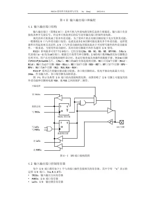
PORTx:读PORTX,是直接读引脚上的电平状态(见图)。
写PORTX,将数值写入引脚数据锁存器(见图)。
PIC单片机引脚操作模式为“读出--修改--写入”,使用PORTX操作引脚时应注意两点,一是在单片机初始化之后的运行中尽量不改变端口输入输出方向,容易出问题,二是IO端口避免链接容性负载,此种在高速操作IO端口时会出问题,比如输出快速变化的高低电平时,每次输出都会读取一次端口寄存器数值。
LATx:读LATX,得到保存在端口数据锁存器中的值(该值为写LATX或PORTX后所得)。
写LATx,讲数值写入引脚数据锁存器,与写PORTX效果相同。
通过LATX操作端口IO,可避免上述因“读出--修改--写入”模式造成的问题。
ODCx:将引脚的相应位置1可配置引脚为漏极开路输出。
3、IO端口使用原则
(1)端口用作出入,需要直接读取外部引脚上的电平状态,使用PORTX寄存器:int V ALUE=PORTA;
(2)端口用作输出,输出高低电平,驱动芯片等使用LATX寄存器:
LATA=0XFFEE;
4、IO端口使用的位操作
可以使用P24FJ32GA004.h中定义的位操作宏定义对单片机的IO端口以及其他众多单片机寄存器进行位操作。
如:_LATB0=1; RB0输出高电平
以端口B为例,针对PIC24F系列的位操作被定义如下形式:
/* TRISB */
#define _TRISB0 TRISBbits.TRISB0
#define _TRISB1 TRISBbits.TRISB1
……
#define _TRISB15 TRISBbits.TRISB15
/* PORTB */
#define _RB0 PORTBbits.RB0
#define _RB1 PORTBbits.RB1
……
#define _RB15 PORTBbits.RB15
/* LATB */
#define _LATB0 TB0
#define _LATB1 TB1
……
#define _LATB15 TB15
/* ODCB */
#define _ODB0 ODCBbits.ODB0
#define _ODB1 ODCBbits.ODB1 ……
#define _ODB15 ODCBbits.ODB15。