RB08机器人使用说明书(2012年3月第2版)-2012-03-16定稿
- 格式:pdf
- 大小:1.29 MB
- 文档页数:64
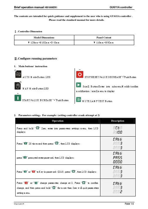
The contents are intended for quick guidance and supplement to the user who is using GU611A controller .Please read the standard manual for more details..Ⅰ Controller DimensionModel Dimensions Panel CutoutW120mm×H102mm ×D48mmW110mm ×H92mm.Con Ⅱfigure running parameters1. Main buttons` instructionAUTO Mode Button /LEDMAN Mode Button/LEDSTART/V ALUE INCREASE “+”Push ButtonSTOP/RESET/V ALUE DECREASE “-”Push ButtonScroll Button/Enter into submenu/Modify/confirm modification / scroll menu to displayMUTE/LAMP TEST Button2. Parameters setting :For example: (setting controller crank attempt at 2)Press and hold “.ⅢParameters setting1.System Parameters:NO. Items Preset NO. Items Preset1.1 CT ratio 0()℃1.2 VT ratio 11.3 Rated ph-voltage1.4 AC voltage type1.5 Startup mode 0S1.6 Oil pressure unit0 2.7 Over current pre-alarm90% 2.8 Over current alarm115% 2.9 Over current action10S2.5 Hz low alarm 5S2.6 Hz high alarm 5S3. Engine Parameters:NO. Items Preset NO. Items Preset3.1 Pair of poles 10s3.2 Fuel mode 300S3.3 T-sensor type 20S3.4 P-sensor type 0RPM3.5 Start delay 1440RPM3.6 Crank attempt 1600RPM3.7 Crank time 1710RPM3.8 Crank rest 1.1BAR3.9 Crank cutout RPM 1.4BAR3.10 Crank cutout Oil-P92℃3.11 cutout P-delay100℃3.12 Idle delay 8.0V3.13 Preheat delay 28.0V3.14 Preheat mode 8.0V4.Configurable Inputs and Outputs:NO. Items Preset NO. Items Preset4.1 Configurable input 1 2S4.2 Configurable input 2 2S4.3 Configurable input 3 24.4 Input 1 delay 35. Mains ParametersNO. Item Preset NO. Item Preset5.1 Low Mains voltage 5S5.2 High Mains voltage 5S5.3 Mains frequency6.6 MAINS V2 offset6.7 MAINS V3 offset6.8 Pressure offset6.9 Temperature offset6.10 Batt. V offsetMenu notesl The optional items for P/T-sensor:Co de The brand model of LOP sensor The brand model of HET sensor0 not used not used1 close for low oil pressure close for high temperature2 open for low oil pressure open for high temperature3 VDO 5 bar VDO 120 ℃4 VDO 10 bar VDO 150 ℃5 Datcon 7 bar Datcon6 Murphy7 bar Murphy7 Pre-set 1 PT1008 Pre-set 2 Pre-set 19 Pre-set 3 Pre-set 210 Pre-set 4 Pre-set 311 configured by user Pre-set 412 configured by user●The optional items for configurable input:Co de Optional Function Co de Optional Function0 not used 7 Emergency stop1 Pre-alarm (active immediately) 8 Remote start signal2 Shutdown Alarm (active immediately) 9 Mains Aux. Switch closed3 Pre-alarm (active after safety-on delay) 10 Gen Aux. Switch closed4 Shutdown Alarm (active after safety-on delay) 11 Low fuel level5 LOP switch 12 Lamp test6 HET switch●The optional items for configurable output:Co de Failure Type Define Co de Failure Type Define0 Not used 1 Over current tripping2 Alarm3 Pre-alarm4 Idle 0 (N.C.)5 Preheat6 Speed up7 Reserved8 Fuel pump control 9 Running10 System in AUTO mode 11 Reserved12 System in MAN mode 13 Reserved14 Idle 1 (N.O.) 15 MCB failure (within 5s)16 GCB failure (within 5s) 17 Fail to startl Code Table for Failure:Name Code Name CodeCHARGE FAILUREBA TT. UNDER VOLTBA TT. OVER VOLTSTART FAILUREⅣ.TYPICAL WIRING DIAGRAMNOTE: If pin no. “16” is not used, DO NOT connect to negative.If you want more technical support, please call service hotline: 400 888 3388。

2023年家用机器人操作与维护使用说明书使用说明书2023年家用机器人操作与维护一、机器人简介2023年家用机器人是一款智能家居助手,具备多种功能和特性,能够为您提供便捷的家庭生活服务。
本使用说明书将详细介绍机器人的操作方法和维护要点,以帮助您充分了解和使用本机器人。
二、安全须知1. 在使用机器人之前,请仔细阅读本使用说明书,并按照说明操作。
2. 请确保机器人周围的环境安全,避免机器人碰撞到家具、墙壁等物体。
3. 请勿将机器人暴露在高温、潮湿或有明火的环境中,以免损坏机器人。
4. 儿童在使用机器人时,应在成人监护下进行操作,避免安全事故发生。
三、操作指南1. 启动机器人按下机器人上的电源按钮,待机器人完成自检后,即可启动。
2. 语音交互与机器人进行语音交互,可以使用指令控制机器人的行动,例如: - "机器人,打开窗帘":机器人将协助您打开窗帘。
- "机器人,播放音乐":机器人将为您播放您喜爱的音乐。
- "机器人,帮我查天气":机器人将为您查询当天的天气情况。
3. 家务协助机器人具备清扫、烹饪、洗衣等家务助手功能,您可以通过语音指令或通过手机App进行操作。
4. 安防监控机器人配备智能摄像头和传感器,可以实时监控您的家庭安全状况,并在发现异常时及时通知您。
四、维护指南1. 保持清洁定期清洁机器人的表面和传感器,避免灰尘和污渍影响机器人的正常运行。
2. 更新软件定期更新机器人的软件版本,以获得更好的功能和用户体验。
3. 充电与电池管理当机器人电池电量低时,将其连接至充电器进行充电。
请勿长时间让机器人处于低电量状态,以免影响电池寿命。
4. 故障排除当机器人出现故障或异常时,请先检查是否符合使用条件,并尝试重新启动机器人。
若问题仍未解决,请联系售后服务中心。
五、注意事项1. 本机器人仅适用于家庭环境,禁止将其用于商业、非法等其他领域。
2. 请勿将机器人浸泡于水中,以免发生电气故障。

在本工业机器人产品使用说明书中,我们将尽力叙述各种与该产品使用相关的事项。
限于篇幅限制及产品具体使用等原因,不可能对产品中所有不必做和/或不能做的操作进行详细的叙述。
因此,本产品使用说明书中没有特别指明的事项均视为“不可能”或“不允许”进行的操作。
本产品使用说明书的版权,归广州数控设备有限公司所有,任何单位与个人进行出版或复印均属于非法行为,广州数控设备有限公司将保留追究其法律责任的权利。
IRB165A1-2790搬运机器人 使用说明书(机械分册)II前 言尊敬的客户:对您惠顾选用广州数控设备有限公司RB165A1-2790搬运机器人(简称机器人)产品,本公司深感荣幸并深表感谢!为保证产品安全、正常与有效地运行,请您务必在安装、使用产品前仔细阅读本机器人使用说明书。
安 全 警 告操作不当将引起意外事故,必须要具有相应资格的人员才能使用及操作本产品。
前言、安全注意事项III 安全注意事项使用前(安装、运转、保养、检修等),请务必熟读并全部掌握本使用说明书和其他随行文件资料。
在熟知全部设备知识、安全及注意事项后才能开始使用。
本使用说明书中的安全事项分为“危险”、“注意”、“强制”、“禁止”四类,将分别说明。
危险 误操作时有危险,可能发生死亡或重伤事故。
注意 误操作时有危险,可能发生中等程度伤害或轻伤事故。
强制 必须严格遵守的事项 。
禁止 禁止的事项。
另外,即使是“注意”所记载的内容,也会因情况不同而产生严重后果,因此任何一条注意事项都极为重要,请务必严格遵守。
RB165A1-2790搬运机器人 使用说明书(机械分册) IV强制● 《RB165A1-2790搬运机器人 使用说明书(机械分册)》是以机器人的本体结构内容为中心的技术资料。
为确保本产品的正常使用和妥善保养及维修,其中包括安全注意事项、使用注意事项、详细的规格说明、保养及检修的项目等内容。
请务必在认真阅读并充分理解和掌握的基础上使用。
● 另外,关于安全的有关内容记载在本产品的《工业机器人 使用说明书(电气分册)》的“第一章 安全设备”中,阅读本使用说明书前,请务必熟读安全内容,以确保正确使用。

USER MANUALIMPORT ANT SAFETY INSTRUCTIONSWARNING: When using electric products, basic cautions should always be followed, including the following.1. Read all safety and operating instructions before using this product2. The product should be powered by a three pin `grounded (or earthed) plug connected to a power socket with a grounded earth outlet.3. All safety and operating instructions should be retained for future reference4. Obey all cautions in the Operating instructions and on the back of the unit5. All operating instructions should be followed6. This product should not be used near water, i.e. a bathtub, sink, swimming pool, wet basement, etc.7. This product should be located so that its position does not interfere with its proper ventilation. It should not be placed flat against a wall or placed in a built up enclosure that will impede the flow of cooling air.8. This product should not be placed near a source of heat such as stove, radiator, or another heat producing amplifier.9. Connect only to a power supply of the type marker on the unit adjacent to the power supply cord.10.Never break off the ground pin on a power supply cord.11.Power supply cords should always be handled carefully. Never walk or place equipment on power supply cords. Periodically check cords for cuts or signs of stress, especially at the plug and the point where the chord exits the unit.12.The power supply cord should be unplugged when the unit is to be unused for long periods of time.13.If this product is to be mounted in an equipment rack, rear support should be provided.14.The user should allow easy access to any mains plug, mains coupler and mains switch used in conjunction with this unit thus making it readily operable.15.Metal parts can be cleaned with a damp cloth. The vinyl covering used on some units can be cleaned with a damp cloth or ammonia based household cleaner if necessary. Disconnect the unit from the power supply before cleaning.16.Care should be taken so that objects do not fall and liquids are not spilled into the unit through any ventilation holes or openings. On no account place drinks on the unit.17. A qualified service technician should check the unit if:18.The user should not attempt to service the equipment. All service work is done by a qualified service technician.19. Exposure to extremely high noise levels may cause a permanent hearing gloss. Individuals vary considerably in susceptibility to noise induced hearing loss, but nearly everyone will lose some hearing if exposed to sufficiently intense noise for a sufficient time. The U.S. Government's Occupational Safety and Health Administration (OSHA) has specified the following permissible noise level exposure. Duration Per Day In Hours Sound Level dBA, slow response8 9069249539721001 ½1021105½110¼ or less 115According to OSHA, any exposure in excess of the above permissible limits could result in some hearing loss. Ear plugs or protectors in the ear canals or over the ears must beworn when operating this amplification system in order to prevent a permanent hearing loss if exposure exceeds the limits set forth above. T o ensure against potentially dangerous exposure to high sound pressure levels it is recommended that all persons exposed to equipment capable of producing high sound pressure levels such as this amplification system be protected by hearing protectors while this unit is in operation.!The power cord has been damaged!Anything has fallen or spilled into the unit !The unit does not appear to operate correctly!The unit has been dropped or the enclosure damaged.BEFORE SWITCHING ONAfter unpacking your amplifier check that it is factory fitted with a three pin 'grounded' (or earthed) plug. Before plugging into the power supply ensure you are connecting to a grounded earth outlet.If you should wish to change the factory fitted plug yourself, ensure that the wiring convention applicable to the country where the amplifier is to be used is strictly conformed to. A s an example in the United Kingdom the cable colour code for connections are as follows.NOTEThis manual has been written for easy access of information. The front and rear panels are graphically illustrated, with each control and feature numbered. For a description of the function of each control feature, simply check the number with the explanations adjacent to each panel.Y our Laney amplifier has undergone a thorough two stage, pre-delivery inspection, involving actual play testing.When you first receive your Laney Bass amp, follow these simple procedures:(i) Ensure that the amplifier is the correct voltage for the country it is to be used in.(ii) Connect your instrument with a high quality shielded instrument cable. Y ou have probably spent con siderable money on your amplifier and guitar - don’t use poor quality cable it won’t do your gear justice.Please retain your original carton and packaging so in the unlikely event that some time in the future your amplifier should require servicing you will be able to return it to your dealer securely packed.Care of your Laney amplifier will prolong it's life.....and yours!EARTH OR GROUND - GREEN/YELLOW NEUTRAL - BLUELIVE - BROWNINTRODUCTIONThe RB2 is a 30W bass combo with a 10 inch loudspeaker in a sturdy wooden cabinet. Its features include; two ¼” jack inputs for Normal / Hi level signals, a gain control and a switchable compressor, a flexible EQ system with Bass, swept Mid and T reble control followed by an overall Volume. Should you need to play along to CDs/MP3s you can plug the output of your player into the CD/line in socket. A headphone socket is also provided for private practice, and an external speaker socket for connecting additional cabinets. A Direct out allows you to connect to a PA or recording device. An explanation of these features follows on pages 6-8.Dear Player,Thank you very much for purchasing your new Laney product and becoming part of the worldwide Laney family. Each and every Laney unit is designed and built with the utmost attention to care and detail, so I trust yours will give you many years of ney products have a heritage which stretches back to 1967 when I first began building valve amplifiers in my parent’s garage. Since then we have moved on from strength to strength developing an extensive range of guitar, bass, public address and keyboard amplification products along with a list of Laney endorsees that includes some of the world’s most famous and respected musicians. At the same time we believe we have not lost sight of the reason Laney was founded in the first place - a dedication to building great sounding amplification for working musicians. Warm Regards,Lyndon Laney CEONormal and High inputs are provided for connection of bass guitars. High output basses, either Active or Passive should be connected via the High socket. Low output basses should be connected using the normal input. High output basses may also be placed in the Normal input if pre-amp overloading is desired.This control is used to set the level of gain present in the pre-amp. producing distortion. The Gain control should be used in conjunction with the signal characteristics.Engages and disengages the on-board compressor, this compresses the input-signal giving a punchier sound. In association with the compressor is an LED indicating that the compressor is active. The amount of compression is controlled by the Gain control. The higher the setting the more compression. With most guitars compression will begin at about 5-6 on the control. It is possible to have the compressor engaged but it only be active during certain periods of playing - typically the most dynamic sections.Controls the boost and cut of the low-frequency response of the pre-amplifier.FRONT P ANEL CONTROLST o access low mid-frequencies turn the frequency control anticlockwise, to access higher mid frequencies turn the frequency control clockwise.Controls the boost and cut of the high-frequency response of the pre-amplifier.Sets the overall listening level of the amplifier.RCA/Phono connections provided for connecting an external sound source such as; CD players, MP3 players, Minidisc etc.This socket provides a balanced low-impedance output-signal from the pre-amplifier taken before the Master Volume but after any tone correction, used for direct-injection of the amplifier signal to a mixing-desk or additional power-amplifier.This socket(s) should be used to connect an external cabinet. The impedance of the extension-cabinet must not be less than 4 Ohms. Connecting cabinets that have a lower impedance than 4 Ohms will result in the amplifier overheating. Continual use in this manner may cause permanent damage. Connecting a cabinet with an impedance of greater than 4 Ohms will cause no damage to the amplifier but will result in a reduced output level. (When using an external cabinet the internal speaker is automatically disconnected)Socket for connecting headphones. With headphones connected, the internal and any externally connected loudspeakers are automatically switched off.Indicates power is connected and the amplifier is switched on.(Always switch off and disconnect power cord when not in use)Main power on/off switch.Power inlet socket. Connect to your power source. Make sure the specified voltage is correct for your country!The mains safety fuse for the unit is contained within this drawer.USE ONLY THE CORRECT SIZE AND RATING OF FUSE AS SPECIFIED ON THE PANEL.The mains fuse ratings are detailed in the specs section at the rear of this manual.Serial Number and model of your unit.REAR P ANEL CONTROLSu d s p e a k e r C a b l eHIUSER SETTINGSFound some cool settings you want to keep? Make a note of them here:General NotesAmplifier connection: In order to avoid damage, it is advisable to establish and follow a pattern for turning on and off your equipment. With all system parts connected, turn on source equipment, tape decks, cd players, mixers, effects processors etc. BEFORE turning on your Bass Amplifier. Many products have large transient surges at turn on and off which can cause damage to your speakers. By turning on your Bass Amplifier LAST and making sure its Volume control is set to minimum any transients from other equipment will not reach your loudspeakers. Wait until all system parts have stabilised; usually a couple of seconds. Similarly when turning off your system always turn down the Volume control on your Bass Amplifier and then turn off its power before turning off other equipment.Cables: Never use shielded or microphone cable for any speaker connections as this will not be substantial enough to handle the amplifier load and could cause damage to your amplifier system.Caution:These professional loudspeaker systems are capable of generating very high sound pressure levels. Use care with placement and operation to avoid exposure to excessive levels that can cause permanent hearing damage. (Refer to guidelines on page 2)Servicing: The user should not attempt to service these products. Refer all servicing to qualified service personnel.SPECIFICA TIONSSupply Voltage~100V , ~120V , ~220V , ~230V , ~240V 50/60Hz Factory Option Mains Fuse ~220V>~240V = T250mA L. ~100>~120V = T500mA L (Time delay)Power Consumption 50WOutput Power Rating 30WLoudspeaker 10” Custom Designed DriverFeatures Normal + Hi InputsSwitchable Compressor with Activity light.Clip distortion limiter.EQ Bass (Shelving)Paramid (KHz Peaking)D.I.Y es, Balanced Jack. (Can be used for T uner)Extension Loudspeaker Socket (4 Ohms minimum, disconnects internal speaker)Input Impedance 1M Ohm/100pFRecommended Min Extension Speaker Power 80WRecommended Richter Extension Cab RB410 / RB115Size 440*390*257(H*W*D)Unit Weight 11.75 KgPacking Weight 13 Kg±12dB at 65Hz,±12dB at 200Hz > 2T reble (±15dB at 3.5KHz, Shelving)This product conforms to:European EMC directive(2004/108/EC), Low Voltage Directive (72/23/EEC) and CE mark Directive (93/68/EEC)Page 11 /12LaneyOPERATING INSTRUCTIONSIn the interest of continued product development, Laney reserves the right to amend product specification without prior notification.POWER TO THE MUSIC Laney@。

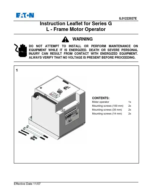
IL01222027EEffective Date 11/07Instruction Leaflet for Series G L - Frame Motor OperatorDO NOT ATTEMPT TO INSTALL OR PERFORM MAINTENANCE ON EQUIPMENT WHILE IT IS ENERGIZED. DEATH OR SEVERE PERSONAL INJURY CAN RESULT FROM CONTACT WITH ENERGIZED EQUIPMENT.ALWAYS VERIFY THAT NO VOLTAGE IS PRESENT BEFORE PROCEEDING.WARNINGRemove existing two screws from primary cover of breaker.Assemble support onto the breaker with four mounting screws supplied. Torque to 0.44 to 0.6 N.m or 4 to 5 in. lb.4•Turn breaker to the “OFF” position first.•Line up breaker handle and molded trigger of motor operator, and position motor operator on the breaker.Mount motor operator to breaker using mounting screws. Torque to 0.44 to 0.6 N.m or 4 to 5 in. lb.SupportMolded Trigger Mounting Screws (14 mm length)Breaker HandleMounting Screws(35 mm length) Mounting Screws(100 mm length)Manual OperationsMove the slide knob to the MANUAL position to expose the manual operating shaft located under the slide knob. The control power supply is cut off automatically.Insert the operating key into shaft slot. Turn the key clockwise to verify the breaker can be closed Leave breaker in the ON position. Press the manual PUSH-TO-TRIP button on the breaker to trip the breaker. Check that the display indicates the TRIP position.Turn the operating key clockwise (approximately 180°) again. This should reset the breaker. Turn the key (Clockwise only)Status IndicationPUSH-TO TRIP ButtonOpetating keyEffective Date 11/07Motor Operator Electrical DataVoltage Frequency Inrush Current 24VDC Application110-127VAC/110-125VDC Application48VDC Application9Lock-Off LeverLOCK-OFFMove slide knob to AUTO position. Pull outthe Lock-Off lever when breaker is in OFFposition, insert one to three padlock shacklesup to 6mm (.25 inch) in diameter.CAUTIONThe motor operator cannot be locked offwhile it is in the ON position.Printed in TQC。
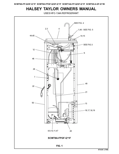
HALSEY TAYLOR OWNERS MANUALUSES HFC-134A REFRIGERANTSEE FIG.3FIG. 12,341,46 - SEE FIG. 514,15122976208,9,10,11,47SEE FIG. 4SCWT8A-FPGF-Q*1F97323C (7/98)F IG . 2E = I N S U R E P R O P E R V E N T I L A T I O N B Y M A I N T A I N I N G 4" (102m m ) (M I N .) C L E A R A N C EF R O M C A B I N E T L O U V E R S T O W A L L .A S EG U R E U N A V E N T I L A C I ÓN A D E C U A D A M A N T E N I E N D O U N E S P A C I O E 4" (102m m ) (M ÍN .) D EH O L G U R A E N T R E L A R E JI L L A D E V E N T I L A C I ÓN D E L M U E B L E Y L A P A R E D A S S U R E Z -V O U S U N E B O N N E V E N T I L A T I O N E N G A R D A N T 4" (102m m ) (M I N .) E N T R E L E S ÉV E N T S D E L E N C E I N T E E T L E M U R .F = P O W E R C O R D 4' (1219m m ) L O N G C A B L E E L ÉC T R I C O D E 4' (1219m m ) P I E , D E L A R G O C O R D O N D A L I M E N T A T I O N 4' (1219m m )G = W A L L S C R E W H O L E S A G UJ E R O S D E T O R N I L L O S D E P A R E D T R O U S D E V I S D U M U R H = 2 X 4 B L O CK I N G BL O Q U E O D E 2 X 4B L O C 2 X 4F I N I S H E D F L O O R P I S O A C A B A D O P L A N C H E R F I N IL E G E N D /L E Y E N D A /L ÉG E N D E A = R E C O M M E N D E D W A T E R S U P P L Y L O C A T I O N 3/8 O .D . U N P L A T E D C O P P E R T U B E C O N N E C T S T U B O U T 1-1/2 I N . (38m m )F R O M W A L L S H U T O F F B Y O T H E R S S E R E C O M I E N D A U B I C A R E L T U B O C O R T O D E C O N E X I ÓN A L T U B O D E C O B R E S I N C H A P A R D E 3/8" D E D I ÁM . E X T . A 1-1/2"(38 m m ) F U E R A D E L A L L A V E D E P A S O E N L A P A R E D C O L O C A D A P O R T E R C E R O S . E M P L A C E M E N T R E C O M M A N D É D 'A L I M E N T A T I O N E N E A U P A R T U B E E N C U I V R E N O N P L A Q U É D E 3/8 P O . (9,5 m m ) D .E .C O N N E C T A N T U N E T U Y A U T E R I E D E 1-1/2 P O . (38 m m ) D E P U I S L E R O B I N E T D 'A R R ÊT F O U R N I P A R D 'A U T R E S .B = R E C O M M E N D E D L O C A T I O N F O R W A S T E O U T L E T 1-1/4 O .D . D R A I N U B I C A C I ÓN R E C O M E N D A D A P A R A E L D R E N A J E D E S A L I D A D E A G U A , D E 1¼ D E D I ÁM E T R O .E M P L A C E M E N T R E C O M M A N D É P O U R L E D R A I N D E D .E . 1-1/4" D E S O R T I E D E A U .C = 1-1/4 T R A P N O T F U R N I S H E D P U R G A D O R D E 1¼ N O P R O P O R C I O N A D O S I P H O N 1-1/4 N O N F O U R N I D = E L E C T R I C A L O U T L E T L O C A T I O N U B I C A C I ÓN D E L A T O M A D E E L E C T R I C I D A D E M P L A C E M E N T D E L A P R I S E D E C O U R A N T97323C (7/98)FIG. 4CORRECT STREAM HEIGHTFIG. 5FIG. 3PUSH BUTTON VALVE ADJUSTMENT13024262523,27,28ADJUST THIS SCREW TO ELIMINATE VALVE LEVER "FREE PLAY" OR CONTINUOUS FLOW FROM BUBBLERSTREAM HEIGHTADJUSTMENT SCREWP/N 730856151640GLASS FILLER 8561OPTIONAL PLATFORM GLASS FILLER(NOT SHOWN)P/N 730848051640GLASS FILLER 8480P/N 100322740560GASKET - BLACKP/N 100322740560GASKET - BLACKP/N 15009CNIPPLE - GLASS FILLER97323C (7/98)ITEM NO.PART NO.DESCRIPTION51544C 10263993164016027050864017140374259011100834389066504C 66505C 66506C 31513C 35787C 35762C 35775C 31034C 31027C 35840C 35843C 19424390155035766C 35768C 45679C 45678C 66251C 66252C 66253C 10145343164010150753155031490C 31492C 10420954373030699C 70018C 40267204373066201C 66202C 66203C 66255C 66229C 66257C 19266845155035887C 15005C 26860C 26861C 26862C 50986C 61314C 55996C 55880C 11105104355050770C 11007704389010141825155070184C 401507143730101473543730110208243890100631242700101482131870111088440150724373040150693156055885C 55913C 15008C 35844C 70682C See Color T able See Color T able See Color T ableBubbler Drain Plug Strainer Plate BasinScrew #10-24 x 5/8 HHMS Evaporator (4 GPH)Evaporator (8 GPH)Evaporator (14 & 20 GPH)Cold ControlCompressor Serv. Pak (4 & 8 GPH)Compressor Serv. Pak (14 GPH)Compressor Serv. Pak (20 GPH)Overload/Relay Assy (4 & 8 GPH)Overload/Relay Assy (14 GPH)Overload (20 GPH)Relay (20 GPH)Electrical ShieldRelay Cover (4, 8 & 14 GPH)Relay Cover (20 GPH)T ailpipe (4 GPH)Precooler (8, 14 & 20 GPH)Condenser (4 & 8 GPH)Condenser (14 GPH)Condenser (20 GPH)Cap Push Button Push Button StemFan Motor (4, 8, & 14 GPH)Fan Motor (20 GPH)Fan Blade (4, 8, & 14 GPH)Fan Blade (20 GPH)Fan Blade Nut Fan Motor Bracket Drier (4 & 8 GPH)Drier (14 GPH)Drier (20 GPH)Heat Exchanger (4 & 8 GPH)Heat Exchanger (14 GPH)Heat Exchanger (20 GPH)Power Cord (4, 8, & 14 GPH)Power Cord (20 GPH)Regulator Retaining Nut Regulator Lever Pivot BracketRegulator Retaining Bracket Regulator Holder Regulator StrainerRegulator Mounting Bracket Nylok Nut 1/4-20Snap Bushing WasherCompression Spring Cotter PinAlignment Bracket Foot Pedal Pull Rod Foot Lever Pin Foot Pedal Snap Bushing Hex NutBase Mounting Bracket T oe PlateNut 1-1/4 Slip Nut Adaptor - Drain Nipple - Bubbler Capacitor (20 GPH)T ee - 1/4Side Panel - Right Side Panel - Left Front PanelITEMIZED PARTS LIST12345678*91011121314151617181920212223242526272829303132333435363738394041424344454647484950NS*INCLUDES RELAY & OVERLOAD. IF UNDER WARRANTY, REPLACE WITH SAME COMPRESSOR USED IN ORIGINAL ASSEMBLY .NOTE: All correspondence pertaining to any of the above water coolers or orders for repair parts MUST include Model No. and Serial No. of cooler, name and part number of replacement part.Platinum (PV)Almond (AV)Slate (SV)Stnlss Stl (SS)40153624841026912C 40153624844040153624283040153634841026908C 40153634844040153634283040150744841026904C 401507448440401507442830RIGHT PANEL FRONT PANEL COLOR LEFT PANEL 2222 CAMDEN COURT OAK BROOK, IL 60523PRINTED IN U.S.A.IMPRESO EN LOS E.E.U.U.IMPRIMÉ AUX É.-U.333132NOTE: TOP WASHER IS TO BE PLACED UNDER COTTER PIN WHEN ASSEMBLED353436537383941433540425。

机器人操作说明安全 (1)1).注意事项 (1)2).以下场合不可使用机器人 (1)3).安全操作规程 (1)1.机器人基本操作说明 (2)1.1 机器人显示屏说明 (3)1.2机器人自动运行条件 (5)1.3程序的创建、复制、删除 (6)1.4 程序编辑 (11)1.5 机器人数据备份及恢复 (18)1.6 机器人基本设臵 (23)1.7 报警查看 (30)1.8 I/O操作 (31)1.9码跺编辑 (33)1.10 位臵修改 (38)安全1).注意事项1.FANUC机器人所有者、操作者必须对自己,机器人周边人员和设备的安全负责。
FANUC 不对错误使用机器人的安全问题负责。
FANUC提醒用户在使用FANUC机器人时必须使用安全设备,必须遵守安全条款。
2. FANUC机器人程序的设计者、机器人系统的设计和调试者、安装者必须熟悉FANUC 机器人的编程方式和系统应用及安装。
3. FANUC机器人和其他设备有很大的不同,在于机器人可以以很高的速度移动很大的距离。
2).以下场合不可使用机器人1,燃烧的环境2.有爆炸可能的环境3.无线电干扰的环境4.水中或其他液体中5.运送人或动物6.攀附7.其他!FANUC公司不为错误使用的机器人负责。
3).安全操作规程3.1).示教和手动机器人1)禁止带手套操作示教盘和操作盘。
2)在点动操作机器人时要采用较低的倍率速度以增加对机器人的控制机会。
3)在按下示教盘上的点动键之前要考虑到机器人的运动趋势。
4)要预先考虑好避让机器人的运动轨迹,并确认该线路不受干涉。
5)机器人周围区域必须清洁、无油,水及杂质等。
3.2).生产运行1)在开机运行前,须清楚了解机器人根据所编程序将要执行的全部任务。
2)必须清楚了解所有会左右机器人移动的开关、传感器和控制信号的位臵和状态。
3)必须清楚了解机器人控制器和外围控制设备上的紧急停止按钮的位臵,准备在紧急情况下使用这些按钮。
4)永远不要认为机器人没有移动其程序就已经完成。

User ManualPrecautions!Precautions for BatteriesThe batteries (battery pack or batteries installed) shall not be exposed to excessive heat such as sunshine, fire or the like.Only use attachments/accessories specified or provided by the manufacturer (such as the exclusive supply adapter, battery etc).Do not touch the product when it is moving to avoid hand injuries.1.2.3.All example of use refer to warning card.Keep this product away from fire and keep it dry and clean.Do not squeeze this product with too much force during use.Please use the robot on a flat surface.Maintain an appropriate distance from the robot while it is in operation to avoid injuries.When the robot is in operation, do not forcibly bend its joints as to avoid hand injuries and damage to the machine.Please use the supplied charger for charging the robot.The servos for robot joints are precisely designed and should not be disassembled without authorization. Contact us if necessary.For repair services, go to your local after-sales service center or contact our customer support.When an abnormality is found during debugging, immediately press the Emergency Stop button and cut off the power as to avoid hand injuries and damage to the machine.Take necessary preventive measures when using the robot. Do not use it at heights or near any edges as it may fall off and result in damage.Man-made damage is not covered by our warranty.It is best to use the robot for no longer than 1 hour each time, which will extend the service life of the servo actuators.This product is not intended for children under 14 years of age.You will be provided with software updates if any. For some features, the latest update instruction shall prevail.Please use HDMI cables with good shielding layers and magnetic rings when connecting Yanshee to an external monitor.1. 2. 3. 4. 5. 6. 7. 8. 9. 10. 11. 12. 13. 14. 15.16.Immediately Cut off the power and contact us when:Warning:EmergencyStop buttonCAUTION: Danger of explosion if battery is incorrectly replaced. Replace only with the same or equivalent type.Disposal of a battery into fire or a hot oven, or mechanically crushing or cutting of a battery, that can result in an explosion.Leaving a battery in an extremely high temperature surrounding environment that can result in an explosion or the leakage of flammable liquid or gas.A battery subjected to extremely low air pressure that may result in an explosion or the leakage of flammable liquid or gas.a. The robot smokes or you smell something burning; orb. Water or any other foreign matter enters the robot; orc. The robot is damaged.The User Manual contains important information. Please keep it for future reference!4.5.6.An "Emergency Stop" button is on the top of the robot. When the robot is in operation, you can press this button to immediately cut off the power and stop its operation.01. Packing ListYanshee RobotUser Data Set*1(Quick Start Guide*1,Warranty Card*1)Yanshee Robot components: 1Quick Start Guide: 1Warranty card: 1Battery: 1Power adapter: 1Power cord: 1Spare parts kit: 1 (wires, screws)Screwdriver: 1Charging dock: 1 (Selective Accessories)Sensor Suite: 1 (Selective Accessories)Usage Examples: 1Front view of YansheeBackside view of YansheeIntroduction to GPIO Extended Port Note:Ports 3, 5, 12, 35, 38 and 40 are used, of which ports 3 and 5 are for I2C communication and ports 12, 35, 38 and 40 are for audio I2S signaling.GPIO Pinout DiagramPhysicalPin No.Function Function03. SpecificationsAppearanceElectrical SpecificationsConstructionHumanoid Product ModelERHA101Product NameYanshee ColorSilver Dimensions 370*192*106 (mm)Weight ≈2.05 kgServo Actuators 17 degrees of freedom (DOF)Operating voltage DC 9.6VPower 4.5W~38.4WPower adapterOperating temperature Material Aluminum alloy structure, PC+ABS housing0℃ to 40℃Input: 100V ~240V, 50/60Hz 1.5AOutput: 9.6V, 4AMaster Chip and MemoryNetworkVision SystemSTM32F103VDT6Broadcom BCM2837 1.2GHz 64-bit quad-core ARMv8 Cortex-A53RAM 1GBProcessorMemory 16GBBluetoothBluetooth 4.1Battery capacity 3000mAhCamera 8 mega-pixel camera, fixed focusLightWi-Fi Operating system RaspbianSupports Wi-Fi2.4G802.11b/g/n fast connectEyes: 3-color LED lights *2Chest: 3-color LED notification lights *3Microphone: green indicator *1Charge: dual-color indicator *1AudioSensorsDebugging PortOthers MicrophoneSingle SpeakerStereo speakers *29-axle motion tracking sensor *1Motherboard temperature sensor *1POGO 4PIN *6Built-in sensorExtended port HDMI1GPIO40 (6 of them are used)USB2Control Mode Mobile software (APP); voice control;PC control (Raspbian )KeysFor BT :Maximum OutputPower :5.636 dBmFor 2.4G WIFI :Maximum Output Power : 18.19dBm ON/OFF key on the chest;Emergency Stop key on the top Applicable Standard04. Download and Sign in to Mobile Software (APP)Download the APP:Sign in:APP Download QR Code YansheeMethod 1: Scan the QR code below to enter the APPdownload page where you can click to download theYanshee APP;Method 2: Search and download "Yanshee" in APPStore/Google Play/MyAPP or other platforms.After installing the APP, run the APP and sign in according to the instruction. If you are a registered user, log into the APP directly.Method 3: Log onto /en to searchfor your desired product and download the app.05. Assemble the RobotOpen and log into the APP. Select the assembly tutorial to learn about how to assemble or disassemble the robot from the menu bar.Select the disassembly tutorial to learn about how to disassemble the robot.06. Install and Charge the BatteryInstall the Battery• The battery compartment is below the left arm of the robot. Rotate the battery cover clockwise 90° to unlock it.• Install the battery into the battery cover and then reinstall the battery cover. Rotate the battery covercounter-clockwise 90° to lock it.Charge the BatteryMethod 1: After installing the battery, connect the power cord to the charge port on the back of the robot to charge the battery.07. Start the Robot and Set up the Network Method 2: Place the battery onto the dock charger, and then connect the power cord to the charge port of the dock charger to charge the battery.• Press and hold the button on the chest for 2-3 seconds and release until the indicator is lit up in blue. The robot is booted up after you hear a boot-up sound.• Make sure that both the Bluetooth and Wi-Fi are enabled on the smart devices. Open and log into the Yanshee APP, and click the icon on the upper left of the home screen to connect the robot and set up the network.• Refresh and search devices detected by the system, and select the device to be connected according to the last 4 digits of the MAC address value on the label attached ontothe back of the robot.• After the desired device is selected, the APP will selectthe SSID identical to the local Wi-Fi to be displayed on thepage. Enter the correct Wi-Fi password and click the"Join" button, the robot will set up and connect to thenetwork and also give you a voice prompt, saying"Connecting".Note:You will hear a voice prompt saying "Connected" after successful connection.If the connection fails, you will hear a voice prompt saying, "Connection Failed". In this case, please set up the network again.You do not have to set up the network again for later use, just directly select the desired device from the list.After setting up the network, you can use the APP to controlthe robot and learn more information.08. Use of Mobile APPFall-over ManagementThe mobile APP has a built-in graphic user interface and integrates features including motion tracking, FPV, Blockly visual programming, action readback programming, curriculums, BBS and real-time sensor data view.This feature is off by default. You can enable the feature via the APP. The robot can pick itself up if it falls over whenenabled.Language SwitchingBoth Simplified Chinese and English are supported so far. Goto your APP to select the desired language for the robot.09. Built-in Smart ApplicationsRaspbian OS issued by Raspberry Pi is used as the robot software. This open source software comes with the following features:Speech RecognitionThe robot is configured with speech recognition and semantic recognition for Chinese, allowing you to chat with it.When the robot started, press the button on the chest until the chest lamp turns green, then you can chat with the robot after a "tinkling" sound is heard.Visual ProcessingThe robot is configured with face analysis, face tracking and other features. You can call these functions through the programming tools in the APP or Raspberry Pi system. UBTECH provides the Open SDK API, which enables you to configure your own visual identification functions withthird-party visual identification platforms.Note: please abide by relevant laws when using thethird-party voice platform.Auto Update:After the robot is connected to the Internet, the built-in platform software will automatically detect whether you have the latest version and execute the update process.Do not cut off the power or disconnect from the Internet while updating.10. Open Source Platform(2). Use the USB port on the Yanshee to connect a USB, keyboard and mouse.The Yanshee robot is built on the Raspberry Pi open source platform and open SDK files are provided, allowing a user to configure, learn or develop smart Applications as desired, and also allowing developers to create their own robot.(1). Use an HDMI cable to connect the Yanshee robot to amonitor.(3). You can log onto the Linux system from Raspberry Pi bysimply starting the robot.(4). SDK API and Demo codes are available from(5). For developers, please visit https://to learn more information about Raspberry Pi./enThis device complies with Part 15 of the FCC Rules. Operation is subject to the following two conditions: (1) this device may not cause harmful interference, and (2) this device must accept any interference received, including interference that may cause undesired operation.Note: This equipment has been tested and found to comply with the limits for a Class B digital device, pursuant to Part 15 of the FCC Rules. These limits are designed to provide reasonable protection against harmful interference in a residential installation. This equipment generates, uses, and can radiate radio frequency energy, and if not installed and used in accordance with the instructions, may cause harmful interference to radio communications. However, there is no guarantee that interference will not occur in a particular installation. If this equipment does cause harmful interference to radio or television reception, which can be determined by turning the equipment off and on, the user is encouraged to try to correct the interference by one or more of the following measures:• Reorient or relocate the receiving antenna.• Increase the separation between the equipment and receiver.• Connect the equipment into an outlet on a circuit different from that to which the receiver is connected.• Consult the dealer or an experienced radio/TV technician for help.FCC Caution:Any changes or modifications not expressly approved by the party responsible for compliance could void the user's authority to operate this equipment.IMPORTANT NOTE:FCC Radiation Exposure Statement:This equipment complies with FCC radiation exposure limits should be installed and operated with minimum distance20cm between the radiator & your body.This transmitter must not be co-located or operating in conjunction with any other antenna or transmitter.FCC ID: 2AHJX-YANSHEE-1UBTECH ROBOTICS CORP LTDAdd: 16th & 22nd Floor, Block C1, Nanshan i Park, No. 1001 Xueyuan Road, Nanshan District, Shenzhen City, China P.R.T el: 800-276-61372019-09-25尺寸:95*130mm颜色:四色双面印刷材质:105g铜版纸工艺:骑马钉公差:±0.5mm。

一.示教操作盘面板介绍示教操作盘是主管应用工具软件与用户之间的接口的操作装置。
示教操作盘经由电缆与控制装置内部的主CPU印刷电路板和机器人控制印刷电路板连接。
示教操作盘在进行如下操作时使用。
●机器人的JOG进给●程序创建●程序的测试执行●操作执行●状态确认示教操作盘由如下构件构成。
●横向40字符、纵向16行的液晶画面显示屏●61个键控开关●示教操作盘有效开关●Deadman开关●急停按钮1.示教操作盘有效开关在盘左上角,如右图所示:其将示教操作盘置于有效状态。
示教操作盘处在无效状态下,不能进行JOG进给、程序创建和测试执行等操作。
2.Deadman开关在盘背面,如右图所示两黄色键:示教操作盘处在有效状态下松开此开关时,机器人将进入急停状态。
3.急停按钮在盘右上角,如右图所示红色键:不管示教操作盘有效开关的状态如何,都会使执行中的程序停止,机器人伺服电源被切断,使得机器人进入急停状态。
示教操作盘的键控开关,由如下开关构成。
●与菜单相关的键控开关●与JOG相关的键控开关●与执行相关的键控开关●与编辑相关的键控开关1.与菜单相关的键控开关:1.)、、、、功能( F )键,用来选择液晶画面最下行的功能键菜单。
2.)翻页键将功能键菜单切换到下一页。
3.)、MENU(画面选择)键,按下,显示出画面菜单。
FCTN(辅助)键用来显示辅助菜单。
4.)、、、、、、、、SELECT(一览)键用来显示程序一览画面。
EDIT(编辑)键用来显示程序编辑画面。
DATA(数据)键用来显示寄存器等数据画面。
OTF键用来显示焊接微调整画面。
STATUS(状态显示)键用来显示状态画面。
I/O(输入/输出)键用来显示I/O画面。
POSN(位置显示)键用来显示当前位置画面。
DISP单独按下的情况下,移动操作对象画面。
在与SHIFT键同时按下的情况下,分割画面(1个画面、2个画面、3个画面、状态/1个画面)。
DIAG/HELP单独按下的情况下,移动到提示画面。

初级版产品使⽤说明书2008⽬录第⼀章、初识机器⼈3⼀、组成(集体配置数量参见装箱清单)3(⼀)、结构件3(⼆)、控制电路板3(三)、传感器3(四)、控制程序设计平台3⼆、该产品可以实现的参考作品:3第⼆章、产品构成4⼀、结构件及运动件4(⼀)、底板4(⼆)、连杆类4(三)、连接件4(四)、转向件5(五)、异性杆件5(六)、组件类6(七)、其他零件6⼆、控制电路板7(⼀)、主板7(⼆)、传感器等扩展电路板7三、NFL08全流程图式控制软件设计平台8第三章、跟我学制作“循迹智能车”8⼀、【循迹智能车】的执⾏机构搭建8(⼀)、车⼦底板的搭建8(⼆)、安装车轮9(三)、安装万向轮9(四)、双光反射传感器的安装10(五)、安装电池盒10⼆、【循迹智能车】控制电路的连接11(⼀)、2#控制电路主板功能(集成)11(⼆)、循迹智能车控制电路的连接⽰意图11三、【循迹智能车】控制程序的设计13(⼀)、NFL08全流程图控制程序设计平台的安装13(⼆)、【循迹智能车】控制程序设计步骤(完成简单任务)13(三)、【循迹智能车】控制程序设计步骤(完成循迹任务)19第四章、系统学习产品的使⽤⽅法24⼀、结构件的基本使⽤⽅法24(⼀)、连杆之间的连接⽅法之⼀(直接⽤连接扣)24(⼆)、连杆之间的连接⽅法之⼆(⽤连接扣与弹性垫圈)25(三)、电动机变速箱组件与底板连接25(四)、万向轮组装之⼀26(五)、万向轮组装之⼆26(六)、万向轮与底板组装27(七)、控制电路板与底板连接27(⼋)、电池盒与底板连接27(九)、控制电路主板与电池盒连接28(⼗)、电机变速箱与曲柄的连接28(⼗⼀)、改变变速箱的传动⽐28⼆、控制电路设计29(⼀)、电路主板的输⼊输出⼝29(⼆)、2#控制电路主板功能(集成主板)与传感器、电机变速箱等部件相连⽰意图。
30(三)、补充说明31三、机器⼈控制程序设计平台31NFL08-ZB2(标准版) 31(⼀)、有关“⽂件”的操作命令32(⼆)、有关“程序”编辑的命令33(三)、程序设计的编辑操作37四、程序命令使⽤说明42(⼀)、NFL08-ZB1控制程序设计平台命令集42(⼆)、NFL08-ZB2控制程序设计平台命令集43(三)、制程序设计功能及使⽤44五、⾼级命令介绍53(⼀)、变量处理命令53第五章、常见问题及解决⽅法60该说明书是根据FSX-2008L基本型、FSX-2008S标准型产品编制,这两种产品主要针对初次接触机器⼈的学⽣,以典型作品为线索,⼀步⼀步教你学会制作简易机器⼈。
机器人操作说明书斯图加特航空自动化(青岛)有限公司中国-山东-青岛-高新技术开发区Tel:0532- Fax:0532-1.概要 (3)2.坐标系 (7)3.程序创建 (11)4.动作指令 (12)5.焊接指令 (16)6.摆动指令 (18)7.寻点指令 (20)斯图加特航空自动化(青岛)有限公司中国-山东-青岛-高新技术开发区Tel:0532- Fax:0532-概要•机器人•控制装置•示教器机器人机器人是由通过伺服电机驱动的轴和手腕构成的机构部件。
手腕叫做机臂,手腕的接合部叫做轴杆或者关节。
最初的3轴(J1.J2.J3)叫做基本轴。
机器人的基本构成,由该基本轴分别由几个直动轴和旋转轴构成而确定。
机械手腕轴对安装在法兰盘上的末端执行器(焊枪)进行操控。
如进行扭转、上下摆动、左右摆动之类的动作。
机械臂控制装置机器人控制装置,由电源装置、用户接口电路、动作控制电路、存储电路、I/O电路等构成。
用户在进行控制装置的操作时,使用示教操作盘和操作箱。
动作控制电路通过主cpu印刷电路板,对用来操作包含附加轴在内的机器人的所有轴之伺服放大器进行控制。
- 3 -示教操作盘- 5 -与菜单相关的键控开关与JOG 相关的键控开关与执行相关的键控开关与编辑相关的键控开关2.坐标系坐标系是位确定机器人的位置和姿势而在机器人或空间上进行定义的位置坐标系统。
坐标系有关节坐标系、关节坐标系关节坐标系是设定在机器人的关节中的坐标系。
关节坐标系中的机器人的位置和状态,以各关节的底座侧的关节坐标系为基准而确定。
下图中的关节坐标系的关节值,处在所有轴都为0°的状态.关节坐标系刀具坐标系这是用来定义刀尖点(TCP)的位置和刀具姿势的坐标系.刀具坐标系必须事先进行设定.位定义时.将由机械接口坐标系代替刀具坐标系。
世界坐标系世界坐标系,是被固定在空间上的标准笛卡尔坐标系,其被固定在机器人事先确定的位置。
用户坐标系基于该坐标系而设定。
GSK RMD08工业机器人技术协议甲方(供方):广州数控设备有限公司乙方(需方):目录一、公司简介 (1)二、产品概述 (2)2.1产品特点 (2)2.2全系列产品 (2)三、技术参数 (4)3.1参数说明 (4)3.2外形尺寸 (4)3.3最大运动范围 (6)四、控制器 (7)4.1性能特点 (7)4.2主要参数 (7)五、核心部件配置 (9)六、装箱单 (10)七、安装调试 (11)7.1包装方式 (11)7.2安装尺寸 (11)八、售后服务 (13)一、公司简介广州数控设备有限公司(广州数控、GSK)中国南方数控产业基地,国内技术领先的专业成套机床数控系统供应商。
公司秉承科技创新,以核心技术为动力,以追求卓越品质为目标,以提高用户生产力为先导,主营业务有:数控系统、伺服驱动、伺服电机研发生产,数控机床连锁营销、机床数控化工程,工业机器人、精密数控注塑机研制,数控高技能人才培训。
图1 广州数控产业园广州数控是国内最大的机床数控系统研发、生产基地,科研开发人员800多人,年投入科研经费占销售收入8%以上,年新产品收入占总销售的75%以上。
广州数控拥有国内一流的生产设备和工艺流程,年产销数控系统连续11年全国第一,占国内同类产品市场的1/2份额。
公司科学规范的质量控制体系保证每套产品合格出品。
广州数控拥有完善的服务网络和一流的服务团队,全方位、多层次、科学高效的服务管理方式和手段,保证用户在最短时间得到快捷、可靠、有效的响应。
广州数控以“打造百年企业、铸就金质品牌”的企业理念和“精益求精,让用户满意”的服务精神,通过持续不断的技术进步与创新为提升用户产品价值和效益,为推动数控系统产品国产化过程不懈努力。
二、产品概述2.1产品特点1)具有20年工业控制技术研发和制造经验;2)具有优秀的研发团队不断提高机器人的性能;3)零部件自主知识产权率90%以上;4)产品齐全,应用领域涉及面广,包括搬运、焊接、码垛、水平、并联、喷涂等六大系列20多种型号;5)具有高稳定性、长寿命、容易保养、高性价比等特点;6)可扩展性、坚固耐用、操作简单、高效率、可靠性强、安全性能优越、大工作空间、稳定的高精度性能、专业热忱的高质量服务。
机器人系统操作手册专机部分一、检查1、动力电压交流400V 230V,如果打开柜门小心有电。
2、控制电源直流24V3、气压大于0.6兆帕二、上电图2-1图2-1为未上电状态,如果需要上电需要做好上电前准备:1、检查急停开关是否复位;2、手动/自动开关打到手动;3、无报警信息;4、按下按钮,系统上电;5、上电正常注:紧急状况下,拍下急停按钮,系统断电。
系统复位按钮按下系统复位,可复位故障信息。
急停复位按钮按下急停复位蜂鸣器复位按钮按下可在故障发生时停止蜂鸣器灯测试按钮按下指示灯全亮,检测指示灯是否无输出HOME循环按钮按下设备回到HOME点,即设备初始位置系统暂停按钮按下专机和机器人进入暂停状态,再次按下暂停状态取消三、运行一)自动启动1、将手动/自动按钮切换到自动位置后,控制面板显示状态如下图所示,2、按下系统启动按钮系统启动,控制面板状态下图所示。
3、自动启动完成二)自动状态及单机控制(HMI)1、主画面(仅供参考)主画面,见上图,为设备上电后自动进入的默认页面。
(不同的区域设备号不同,以下以分拣C20为例)设备1723—>1#专机设备1723&1718 –> 1#机器人设备1718—>2#专机设备1713—>3#专机设备1713&1718 –> 2#机器人设备1708—>4#专机设备1708&1703 –> 3#机器人设备1703—>5#专机设备1698—>6#专机设备1698&1703 –> 4#机器人状态显示区:主画面左侧区域为状态显示区,主要显示设备的工作状态,每个工作状态对应一种颜色,例如:故障是紫色,准备好是黄色,运行是绿色。
专机选择区:主画面右侧区域为专机选择区,在自动运行过程中如果需要单台专机单独控制,选择对应按钮进入相应的画面即可。
报警信息区:主画面中下部区域为报警信息区,如果报警发生,此区域只显示简明的报警信息,具体报警容还要参考报警页面的容。
#8 STAINLESS STEEL ELECTRIC MEAT GRINDEROWNER’S MANUALThank you very much for choosing a Kitchener™ product! For future reference, please complete the owner’s record below:Model: _______________ Purchase Date: _______________Save the receipt, warranty and these instructions. It is important that you read the entire manual to become familiar with this product before you begin using it.This machine is designed for certain applications only. The distributor strongly recommends this machine is not modified and/or used for any application other than that for which it was designed. If you have any questions relative to a particular application, DO NOT use the machine until you have first contacted the distributor to determine if it can or should be performed on the product.For technical questions and replacement parts, please call 1-800-222-5381.TECHNICAL SPECIFICATIONSHP 0.35 HPVolts 120VWatts 250WNeck #8Overall Dimensions (L x W x H) 19.3in. x 8.3in. x 13.6in. (490 x 212 x 345 mm) Capacity Per Hour 264 lbs. (Pork) / 198 lbs. (Beef)Motor Speed - No Load 240 RPMHopper Size Elliptic 11.8in. x 7.9in. x 4.3in. (300 x 200 x 109 mm) Inlet Diameter 2in. (51mm)Outlet Diameter 2.4in. (62mm)Plate Diameter 2.4in. (62mm)Size of Plate Holes 3/16in. (4.5mm), 3/8in. (10mm)Stuffing Tubes Included 3/8in. (10mm), 3/4in. (20mm), 1-1/4in. (30mm) Discharge Pan Dimensions (L x W x H) 9.4in. x 8.7in. x 1.6in. (240 x 220 x 42 mm)GENERAL SAFETY RULESWARNING:Read and understand all instructions.Failure to follow all instructions listed below may result in electric shock, fire and/or serious injury.WARNING:The warnings, cautions, and instructions discussed in this instruction manual cannot cover all possible conditions or situations that could occur. It must be understood by the operator that common sense and caution are factors which cannot be built into this product, but must be supplied by the operator.SAVE THESE INSTRUCTIONSWARNING:YOUR SAFETY IS THE MOST IMPORTANT ISSUE WHEN USING ANY ELECTICAL PRODUCT. BASIC SAFETY PRECAUTIONS MUST ALWAYS BE FOLLOWED! •ALWAYS disconnect unit from power source before servicing unit.•NEVER use this appliance outdoors or in a wet or damp environment. Never allow power cord to be exposed to water or any other liquid. Electrical shock may cause serious injury or even death.•ALWAYS check grinder for any damaged parts prior to using, including power cord.•NEVER modify power cord or plug in any way. ALWAYS use the proper outlet with a 3 prong grounded line.•ALWAYS make sure the power switch is in the off position before plugging in or removing the unit’s power cord. NEVER use the cord to remove the plug from the outlet.•NEVER use the appliance in an area where the cord is exposed to possible entanglement.ALWAYS protect the cord from being snagged as this could cause the appliance to be turned over.•NEVER attempt to operate this appliance while under the influence of alcohol, drugs or medications. •NEVER leave your appliance unattended. ALWAYS turn off the power switch and disconnect the unit from the power source before leaving the work area.•ALWAYS keep children and inexperienced users a safe distance away from this appliance.Children and inexperienced users should never be allowed to operate this unit.•Trim all excess tendons, cartilage, cords, blood clots and remove meat from bones.•NEVER leave this appliance unattended while it is in operation or while connected to a power source, which would allow anyone unqualified to turn on this unit.•ALWAYS make certain the appliance is seated firmly on a level, stable surface.•NEVER operate this appliance without animal meat in the unit. Severe damage can occur if unit is run for any length of time without product in the unit.•ALWAYS tie back loose hair and clothing before attempting to operate this appliance and roll back any long sleeves you may be wearing.•ALWAYS remove any rings, watches, bracelets or other jewelry before attempting to operate this appliance. Not doing so could cause serious injury and damage the unit.•ALWAYS wear eye protection (safety goggles) when operating this appliance.•WARNING: NEVER use fingers to push meat into hopper intake. Doing so could result in loss of appendages and serious injury. Always use food plunger.WARNING:NEVER use hands or fingers to pull or scrape meat away from the grinding plate outlet. Doing so could result in loss of appendages and serious injury.•NEVER extend your reach or reach over any object to feed the grinder. Keep a stable balance and firm footing at all times.•NEVER insert any foreign object into this appliance. Always use the accessories that were provided with your unit.•ALWAYS turn off and disconnect the appliance if it becomes jammed. Wait until the unit has come toa complete stop before attempting to remove any jammed matter.•NEVER force this appliance to operate beyond its designed rate. Trying to push the unit will only result in problems. Practice safety and allow the unit to work properly.•NEVER attempt to grind bones, cartilage or tendons. Make sure all metal matter (bullets, shot, etc.) have been removed from all meat.•ALWAYS allow all moving parts to come to a complete stop before using the reverse mode.Reverse mode is designed to run for only a few seconds. Prolonged usage will result in damage to the unit’s motor. Hitting the reverse mode while the unit is still running will also damage the motor. •NEVER attempt to remove or attach the hopper tray, grinder head, locking cap or other accessories while the appliance is in operation or plugged into the power outlet.ASSEMBLY AND OPERATION INSTRUCTIONSBefore Use:✓Disassemble the grinder head and wash each part thoroughly in warm soapy water, removing all food-grade packing grease and oil from the surfaces. Dry all parts before re-assembly.✓Keep packing material for future storage of grinder and grinder parts.Assembly Instructions:✓Insert grinder head into gear housing; be sure that the hopper tray throat is facing upward. Holding grinder head with one hand, place locking knob into the hole on the side of Motor housing and tighten it clockwise (See Fig 1).✓Insert auger into the grinder head. You may need to turn the auger to align it with the drive shaft of the motor (See Fig 2).✓Place cutting knife blade onto Feed Screw shaft of the auger with the Flat edge of blade facing the front (See Fig 3).✓If blade is not seated properly, meat will not be ground.✓Place desired grinding plate next to Cutting Blade. The notch in the plate should align with the protrusion on the grinder head (See Fig 4).✓Firmly screw ring cap onto grinder head. Do not over tighten (See Fig 5).✓Insert the Hopper meat tray onto the throat of the head (See Fig 6).Grinding Instructions:✓For best results, trim all excess tendons, cartilage, cords and blood clots and remove meat from bones.✓Optimal results occur when meat is chilled to 32-34°F before grinding.✓Cut meat into pieces that will easily fit in throat of grinder head. (Approximately 1in. squares.)✓Place cubed meat into tray. Be sure not to over fill the tray. Make sure the throat opening of the tray remains clear and open.✓Place a dish, bowl or tray under grinder head to catch ground meat.✓Switch grinder to on position. Carefully begin to feed meat down the throat. Use plunger to push meat. DO NOT use fingers or utensils other than the plunger provided; bodily injury may occur and you could damage your grinder.If Jamming Occurs or Performance Slows:WARNING:Shut grinder off immediately and remove power cord from outlet.✓Carefully remove Grinder head ring cap, grinder plate and cutting blade.✓Carefully clean grinder plate holes thoroughly and remove any tendons from around cutting blade. ✓Replace cutting blade, grinder plate and screw ring cap back onto grinder head.✓Continue grinding✓Repeat steps as necessary to enhance grinder performance.Grinders Reverse Function:✓Switch off the machine.✓Switch CIRCUIT BREAKER to reset.✓Press OFF/REVERSE to clear any materials that are jamming the machine.✓Reverse operation will continue for as long as OFF/REVERSE is pressed.*Extended use of Reverse is not recommended and will cause damage to motor.✓If performance remains slow or there is still a jam go to steps under “If jamming occurs or Performance slows” above and repeat as needed.Sausage Stuffing Directions:✓Properly prepare casings as directed on casing packaging. Place artificial or natural intestines onto sausage funnel.✓Load hopper with prepared meat and feed meat into grinder head opening before operating unit.Do not operate grinder without meat in grinder head. Damage to auger and/or motor can occur.✓Plug in and turn switch to on position when ready to start.✓Hold the casing on the sausage tube in one hand and slowly let the meat output pull the casing from the tube. Fill casing as desired by holding casing back on tube.✓Twist or tie the sausage into links as desired. Tie end of casing into a knot.✓It is recommended that 2 people perform sausage stuffing.✓Add small amounts of water to your ground meat when stuffing sausage to improve output of meat through sausage stuffing tube.After use:✓Unplug and disassemble all parts and wash thoroughly in soapy water.✓NOTE: Do not place parts in a dishwasher; wash all parts by hand✓You must remove all foreign material from all appliance parts. (Grinding stale bread may help remove food residue.)✓Dry all surfaces.✓Do not use bleach or chlorine-based chemicals to clean. Discoloration of plastic parts can occur.✓Wipe down all non stainless steel parts with a food grade spray. Alternatively, wipe down with a salad oil to keep from rusting.✓Do not immerse motor housing in water. Damage to motor can occur. Wipe with damp cloth to clean.TROUBLE HOOTINGPROBLEMS SOLUTIONSGrinder has no power Check power to outlet. Make sure unit is securely plugged into outletGrinder has no power, but outlet does First, check and reset circuit breaker. Problem may be with switch or power cord. Contact customer service.Grinder hums or runs in only one direction Grinder has switch or internal problem. Try resetting circuit breaker. Contact customer service.Grinder hums or labors to operate Possible cold gear grease problem. Move grinder to warmer area. If this does not work contact customer service.Grinder runs slowly and erratically Possible cold gear grease problem. Move grinder to warmer area. If this does not work contact customer service.Meat is backing up at the back of the grinder Auger is not able to handle large portions of meat. Cut meat into smaller pieces so auger can work properly.Meat is only turning around the auger andcompressing against the head Meat is too warm. Cool meat to a temperature around 40°.Meat does not flow through grinder Make sure grinder head is properly assembled. Check sharpness of knife blade.Meat is backing up at head and will not flow Meat may be snagging on the auger or other parts. Lubricate internal parts with food-grade silicone spray.PARTS DIAGRAMPARTS LISTPart No. Description Qty. Part No. Description Qty.1 Motor Assembly 1 each 21 Gasket 1 each2 Motor Cover 1 each 22 Hex Screw 4 each3 Meat tray 1 each 23 Hex Nut4 each4 Meat Stomper 1 each 24 Flat washer 4 each5 Grinder Head 1 each 25 Elastic washer 4 each6 End Nut 1 each 26 Cable Box 1 each7 Stuffing tubes 3 each 27 Support Base 1 each8(a) Plate - coarse 1 each 28 S/S Cross Screw 4 each 8(b) Plate - fine 1 each 29 Foot 4 each9 Blade 1 each 30 Cable clip 1 each10 Stud 1 each 31 Cable 1 each11 Auger 1 each 32 Waterproof switch 1 each12 Auger Bushing 1 each 33 Hex Screw 4 each 13,14,15,16,17,19 Gear Assembly 1 each 34 Star Handle 1 each18 Front panel of gear box 1 each 35 Receiving meat tray 1 each20 Back Panel of Gear Box 1 eachFor technical questions and replacement parts, please call 1-800-222-5381.WARRANTYOne-Year Limited WarrantyDistributed byNorthern Tool + Equipment Co., Inc.Burnsville, MN 55306-6936Made in China.。