Honeywell STT3000-250系列智能温度变送器 说明书
- 格式:pdf
- 大小:937.60 KB
- 文档页数:6
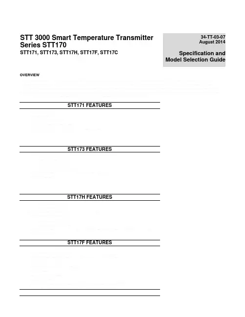
STT 3000 Smart Temperature Transmitter Series STT170STT171, STT173, STT17H, STT17F, STT17C34-TT-03-07August 2014 Specification and Model Selection GuideOVERVIEWThe Honeywell STT170 series of programmable temperature transmitters provides cost effective solutions for temperature monitoring applications. Compared to direct-wired temperature sensor monitoring points, the STT170 series of transmitters delivers increased accuracy, safety and reliability while also reducing wiring costs. These transmitters automatically linearize the temperature output signal bounded by the upper range value and lower range value established by the user. In addition, the user can program high or low limit alarms to activate in the case of sensor failure.STT171 FEATURESAnalog 4-20 mA outputRTD or Ohm inputDIN form B headmountNAMUR NE43 sensor error responseConfigurable using STT17C configuration tool and PCSTT173 FEATURESAnalog 4-20 mA outputRTD, T/C, Ohm or mV inputDIN form B headmountNAMUR NE43 sensor error responseConfigurable using STT17C configuration tool and PCGalvanic isolationSTT17H FEATURESHART™/4-20 mA outputRTD, T/C, Ohm or mV inputSingle or dual (difference or average) sensor inputDIN form B headmountHART Multidrop capableNAMUR NE43 sensor error responseConfigurable using STT17C configuration tool and PC or HART field communicatorGalvanic isolationSTT17F FEATURESFOUNDATION™ fieldbus protocolRTD, T/C, Ohm or mV inputSingle or dual (difference, average or redundant) sensor inputDIN form B headmountFunction blocks: 2 analogue, 1 PIDFISCO certifiedBasic or LAS capabilityGalvanic isolationHART is a registered trademark of the HART Communication Foundation.FOUNDATION is a registered trademark of the Fieldbus Foundation.Dimensions (all models)WiringWiringSTT17C Configuration toolThe STT17C configures the STT171, STT173 and STT17H. The intuitive graphical user interface of the STT17C virtually eliminates the need for operator training after installation on a PC. The STT17C includes all software and transmitter interface hardware necessary to configure the STT171, STT173 and STT17H in non-hazardous work environments.WARNING: The STT17C is not approved for use in Hazardous work environments.System Requirements:Windows® 98SE, ME, 2000 and XP with the following recommendations:MBMemory: 16Display resolution: 800 x 600Hard disk space: 12 MBWindows is a registered trademark of Microsoft CorporationSTT171-BS SpecificationsSTT173-BS SpecificationsSTT17H-BS SpecificationsSTT17H-BN SpecificationSTT17F-BS Specifications** reference temperature 24o COPERATING CONDITIONSAPPROVALSAmbient temperature, rated…………...………-40 to 85o C (-40 to 185oF)Observed Authority requirements:Standard:Humidity…………………………………………0 to 95% RH (non-cond.)EMC 2004/108/ECVibration…………………………………...……Max 4g over 25 to 100Hz Emmission and immunity EN 61326Cold junction accuracy………......……………±0.5o C ATEX 94/9/EC……………………………EN 50014, EN 50020,EN 50281-1-1, EN 50284,ELECTRICAL INPUT SPECIFICATIONSand IEC 60079-27 (FISCO)Supply Voltage…………………………………9 to 30 VDC FM, ASCN…………………………………3600, 3611, 3610In FISCO installations………………………9 to 17.5 VDCCSA, CAN / CSA…………………………C22.2 No. 142, No. 157Consumption……………………………………< 11 mA CAN / CSA…………………………………E60079-0, E60079-11,Warm-up time…………………………..………30 sec E60079-15, UL913, UL1604Response time (programmable)………………1 to 60 sec Galvanic isolation………………………………1500 VAC Ex / I.S. approval:Update time.........................................< 400 msec KEMA 06 ATEX 0046....................... II 1 GD, T65o C (105)CExecution time, PID controller……………….< 200 msec EEx ia IIC T4…T6Execution time, analogue input………………< 50 msecEx II 2(1) GD, T65oC…T105oC EEx ib [ia] IIC T4…T6OUTPUT SPECIFICATIONSApplicable in zone…………………………0, 1, 2, 20, 21 or 22Foundation TM Fieldbus connection:FM, applicable in…………………………IS, CL I, DIV 1, Grp. A-D, T4…T6Foundation TMFieldbus version……………..ITK 4.6AEx ia IICFoundation TMF. capability……………………Basic or LASNI, CL I, DIV 2, Grp. A-D, T4…T6Foundation TMF. function blocks…………….2 analogue and 1 PIDEntity, FM Installation Drawing No (50016325)CSA, applicable in………………………IS, CL I, DIV 1, Grp. A-D, T4…T6Ex ia IIC, AEx ia IICCL I, DIV 2, Grp. A-D, T4…T6Entity, CSA Installation Drawing No (50016325)STT17F-BN Specifications** reference temperature 24o COPERATING CONDITIONS APPROVALSAmbient temperature, rated…………...………-40 to 85o C (-40 to 185o F)Observed Authority requirements:Standard: Humidity…………………………………………0 to 95% RH (non-cond.)EMC 2004/108/EC Vibration…………………………………...……Max 4g over 25 to 100Hz Emmission and immunity EN 61326Cold junction accuracy………......……………±0.5o C ATEX 94/9/EC……………………………EN 60079-0, EN 60079-15 Reference temperature………………………20 to 28o C FM, ASCN…………………………………3600, 3611CSA, CAN / CSA…………………………C22.2 No. 142, No. 213 ELECTRICAL INPUT SPECIFICATIONS CAN / CSA…………………………………E60079-0, E60079-15,Supply Voltage…………………………………9 to 32 VDC UL1604 Consumption……………………………………<11 mA Ex / I.S. approval:Warm-up time…………………………..………30 sec KEMA 06 ATEX 0045 X……………..… II 3 GResponse time (programmable)..................1 to 60 sec EEx nA [L] IIC T4...T6 Galvanic isolation....................................1500 VAC Applicable in zone (2)Update time…………………………………..< 400 msec FM, applicable in…………………………NI, CL I, DIV 2, Grp. A-D, T4…T6 Execution time, PID controller……………….< 200 msec FNICOExecution time, analogue input..................< 50 msec Entity, FM Installation Drawing No (50016325)CSA, applicable in………………………CL I, DIV 2, Grp. A-D, T4…T6 OUTPUT SPECIFICATIONS CL I, Zone 2,Foundation TM Fieldbus connection:Ex nA IIC, AEx nA IIC Foundation TM Fieldbus version.................ITK 4.6Entity, CSA, Installation Drawing No (50016325)Foundation TM F. capability……………………Basic or LAS Max. amb. Temperature for T4…………85o CFoundation TM F. function blocks…………….2 analogue and 1 PID Max. amb. Temperature for T6…………60o CVmax (32V)Li……………………………………………1 HCi……………………………………………2.0 nFSTT171 Custom Configuration Data SheetCustomer P.O. Number __________________________________________________________ Line Item _____________________________________________________________________ Model Number ________________________________________________________________ Tag Number (max 15 char) _______________________________________________________ Honeywell Sales Order Number ___________________________________________________Sensor Type:□ Pt100□ Ni100□ OhmsOutput Values:4 mA Value:20 mA Value: Response time:□ __________ o C □ __________ o C _______ (0.33 – 60 sec) □ __________ o F □ __________ o F□ __________ Ohms □ __________ OhmsOutput Limits:□ Span (4 to 20 mA)□ Max (3.5 to 23 mA)□ Specify Low ______ mA, High _____ mA□ NAMUR NE 43 (3.8 to 20.5 mA)Sensor Error Action:□ Off□ Specify _____ mA□ NAMUR NE 43 upscale (23 mA)□ NAMUR NE 43 downscale (3.5 mA)STT173 Custom Configuration Data SheetCustomer P.O. Number __________________________________________________________ Line Item _____________________________________________________________________ Model Number ________________________________________________________________ Tag Number (max 15 char) _______________________________________________________ Honeywell Sales Order Number ___________________________________________________Sensor Type:□ Pt100 □ Type B T/C Cold Junction Compensation:□ Ni100 □ Type E T/C □ Internal□ Type J T/C □ External / Pt100Wiring: □ Type K T/C □ External / Ni100 □ 2-wire □ Type L T/C□ 3-wire □ Type N T/C□ 4-wire □ Type R T/C□ Type S T/C□ Ohms □ Type T T/C□ mV □ Type U T/C□ Type W3 T/C□ Type W5 T/COutput Values:4 mA Value:20 mA Value: Response time:□ __________ o C □ __________ o C _______ (1 – 60 sec)□ __________ o F □ __________ o□ __________ mV □ __________ mV□ __________ Ohms □ __________ OhmsOutput Limits:□ Span (4 to 20 mA)□ Max (3.5 to 23 mA)□ Specify Low ______ mA, High _____ mA□ NAMUR NE 43 (3.8 to 20.5 mA)Sensor Error Action:□ Off□ Specify _____ mA□ NAMUR NE 43 upscale (23 mA)□ NAMUR NE 43 downscale (3.5 mA)STT17H Custom Configuration Data SheetCustomer P.O. Number __________________________________________________________ Line Item _____________________________________________________________________ Model Number ________________________________________________________________ Tag Number (max 15 char) _______________________________________________________ Honeywell Sales Order Number ___________________________________________________Sensor Input:□ Single Sensor□ Duplex Sensor (Average)□ Duplex Sensor (Differential)Sensor Type:□ Pt100 □ Type B T/C Cold Junction Compensation:□ Ni100 □ Type E T/C □ Internal□ Type J T/C □ External / Pt100Wiring: □ Type K T/C □ External / Ni100 □ 2-wire □ Type L T/C□ 3-wire □ Type N T/C□ 4-wire □ Type R T/C□ Type S T/C□ Ohms □ Type T T/C□ mV □ Type U T/C□ Type W3 T/C□ Type W5 T/COutput Values:4 mA Value:20 mA Value: Response time:□ __________ o C □ __________ o C _______ (1 – 60 sec)□ __________ o F □ __________ o□ __________ mV □ __________ mV□ __________ Ohms □ __________ OhmsOutput Limits:□ Span (4 to 20 mA)□ Max (3.5 to 23 mA)□ Specify Low ______ mA, High _____ mA□ NAMUR NE 43 (3.8 to 20.5 mA)Sensor Error Action:□ Off□ Specify _____ mA□ NAMUR NE 43 upscale (23 mA)□ NAMUR NE 43 downscale (3.5 mA)STTF Custom Configuration Data SheetCustomer P.O. Number __________________________________________________________ Line Item _____________________________________________________________________ Model Number ________________________________________________________________ Tag Number (max 15 char) _______________________________________________________ Honeywell Sales Order Number ___________________________________________________TRANSDUCER BLOCK PARAMETERSSensorInputUnitsTemperatureSensor□o C □Single□o F □ Duplex Sensor (Average)□ mV □ Duplex Sensor (Differential #1 - #2)□ OhmsSensor Type (Sensor 1, Sensor 2)::□ Pt100 □ Type B T/C Cold Junction Compensation:□ Ni100 □ Type E T/C □ Internal□ Pt500 □ Type J T/C □ External / Pt100 2-w□ Ni100 □ Type L T/C □ External / Ni100 3-w□ Cu10 □ Type N T/C□ Type R T/CWiring: □ Type S T/C□ 2-wire □ Type T T/C□ 3-wire □ Type U T/C□ 4-wire □ Type W3 T/C□ Type W5 T/C□ Ohms□ mVSensor Error Detection:#1Sensor□ Lead breakage and short circuit detection disable□ Lead breakage and short circuit enable□ Lead breakage detection enable, short circuit detection disable□ Lead breakage detection disable, short circuit detection enable#2Sensor□ Lead breakage and short circuit detection disable□ Lead breakage and short circuit enable□ Lead breakage detection enable, short circuit detection disable□ Lead breakage detection disable, short circuit detection enableModel Selection Guide (34-44-16-07)Model Selection Guides are subject to change and are inserted into the specifications as guidance only.Prior to specifying or ordering a model check for the latest revision Model Selection Guides which are published at: /Cultures/en-US/Products/Instrumentation/ProductModelSelectionGuides/default.htm34-44-16U-07Issue 13Page 1 of 2STT 3000 Temperature Transmitter Model SelectionSeries STT170Guide* Ex II G D or II 2 (1) G D allows for installation in potentially explosive atmospheres caused by the presence of combustible dusts only when mounted in a metal enclosure of form B according to DIN 43729 (Head-Mount enclosure) that provides a degree of protection of at least IP 6X in accordance with EN 60529, that is suitable for the application and is correctly installed.Model Selection Guide, (34-44-16-07) cont.STT17 _bAvailability(STT171, STT173, STT17H) Tag Number, CJC, Sensor Type, Sensor Wiring, Temperature Units, URV/LRV, Output Range, Output Limits, Sensor Error Action, Response Time.(STT17F ) Tag Number, Sensor Type, URV/LRV, Burnout- High or Low, Response TimeOrdering Example: STT17H-BN-0-000-EN0-000-00** If Custom Configuration option "T" or the Custom Calibration option "C" is ordered, the configuration or calibrationinformation required must me be entered as a note on the order. Any of the following elements can be included, based on the selected model number:Sales and ServiceFor application assistance, current specifications, pricing, or name of the nearest Authorized Distributor, contact one of the offices below.ASIA PACIFIC Honeywell Process Solutions, (TAC) hfs-tac-********************* AustraliaHoneywell LimitedPhone: +(61) 7-3846 1255 FAX: +(61) 7-3840 6481Toll Free 1300-36-39-36Toll Free Fax:1300-36-04-70China – PRC - Shanghai Honeywell China Inc. Phone: (86-21) 5257-4568 Fax: (86-21) 6237-2826 SingaporeHoneywell Pte Ltd.Phone: +(65) 6580 3278 Fax: +(65) 6445-3033South KoreaHoneywell Korea Co Ltd Phone: +(822) 799 6114 Fax: +(822) 792 9015EMEAHoneywell Process Solutions,Phone: + 80012026455 or+44 (0)1344 656000Email: (Sales)***************************or(TAC)*****************************AMERICA’SHoneywell Process Solutions,Phone: (TAC) 1-800-423-9883 or215/641-3610(Sales) 1-800-343-0228Email: (Sales)***************************or(TAC)*****************************For more informationTo learn more about Temperature Transmitters, visit Or contact your Honeywell Account ManagerProcess Solutions Honeywell1250 W Sam Houston Pkwy S Houston, TX 77042Honeywell Control Systems LtdHoneywell House, Skimped Hill Lane Bracknell, England, RG12 1EB34-TT-03-07 August 20142014 Honeywell International Inc.Shanghai City Centre, 100 Jungi Road Shanghai, China 20061。
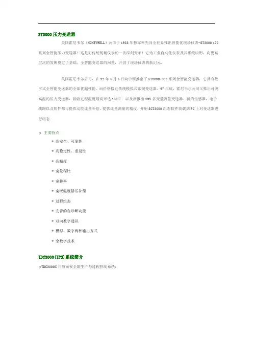
ST3000压力变送器美国霍尼韦尔(HONEYWELL)公司于1983年独家率先向全世界推出智能化现场仪表-ST3000 100系列全智能压力变送器!这是对传统现场仪表的一次深刻变革!它为工业自动化仪表及其系统应用,向更高层次的发展奠定了基础。
全智能变送器的问世,开创了现场仪表的新纪元。
美国霍尼韦尔公司,在92年4月6日向中国推出了ST3000/900系列全智能变送器,它具有数字式全智能变送器的全部优越性能,而价格接近传统模拟式常规变送器。
97年底,霍尼韦尔公司又推出可测高温的压力变送器,接收过程温度最高可达150℃。
以及新推出SMV多变量流量变送器。
新的传感器,电子线路以及软件都可提供动能流量补偿,提供流量测量的精度,并用SCT3000组态软件装载到PC上对变送器进行组态主要特点* 高安全、可靠性* 高稳定性、重复性* 高精度* 宽量程比* 宽移率* 宽域温度静压补偿* 过程组态* 完善的自诊断功能* 双向数字通讯* 模拟、数字两种输出方式* 全数字技术TDC3000(TPS)系统简介TDC3000X开放而安全的生产与过程控制系统:•强大与多样性TDC3000集散控制系统,它是TotalPlant全厂一体化开放概念里的一个平台。
通过一个创新的系统结构和开放的通讯环境,TDC3000将过程和现场仪表的管理(控制层)与生产和信息的管理(信息层)集成在一起,形成一个信息与控制的集成系统。
由此,通过一个单一窗口就可以为企业管理者提供各类数据,辅助他们及时地作出经营决策;同时,系统的通用性和可靠性确保了过程运作的安全进行。
•开放与安全性控制层与信息层的结合,主要是靠系统内的两种双处理器模件--------万能工作站(UxS)与应用模件(AxM)来实现。
这两种模件形成了TDC3000结构中称为X-LAYER的X层。
UxS是TDC3000系统的用户界面,符合X WINDOWS/MOTIF工业标准,它向操作者和工程师提供了一个面向现场过程控制与全厂信息的统一窗口;AxM是TDC3000系统内一个高性能且可靠的应用平台,可执行专用的或开放的应用软件。


霍尼韦尔(honeywell)美国霍尼韦尔(honeywell)ST3000/900系列全智能变送器*Honeywell- HoneywellST3000 系列变送器(备有现货,优势价格,项目协作)差压型号:STD924 STD930 STD974 STD904微差压:STD120 STD110 STD130 STD170 STD125压力型号:STG944,STG974 ,STG94L ,STG97L,STG98L ,STG99L单法兰:STF924 STF932 STF92F STF93F双法兰:STR93D STR94G霍尼韦尔绝压型号:STA922 STA940 STA92L STA94L温度变送器:STT171 STT173 STT250SFC智能手操器STS103-001-00006-24常用型号: 霍尼韦尔差压变送器的型号有以下等:STD924-A1A-00000-MB,SM,1C (0-100KPa)STD924-E1A-00000-AN,MB,SM,1C (0-100KPa)STD924-E1H-00000-MB,S2,SM,1C (0-100KPa)STD930-A1A-00000-MB,SM,1C (0-700KPa)STD930-E1A-00000-MB,SM,1C (0-700KPa)STD930-E1H-00000-S2,MB,SM,1C (0-700KPa)STD924霍尼韦尔差压变送器 霍尼韦尔压力变送器 ST3000STD930STG944/974 霍尼韦尔压力变送器STG944(0~140 至 0~3500kPa)STG974(0~2.1 至 0~21MPa)常用型号: 霍尼韦尔压力变送器的型号有以下等:STG944-A1A-00000-SM,MB,1C (0~140 至 0~3500kPa)STG944-E1A-00000-SM,MB,1C (0~140 至 0~3500kPa)STG944-E1G-00000-S2,SM,MB,1C (0~140 至 0~3500kPa)STG944-A1G-00000-S2,SM,MB,1C (0~140 至 0~3500kPa)STG974-A1A-00000-SM,MB,1C (0~2.1 至 0~21MPa)STG974-E1A-00000-SM,MB,1C (0~2.1 至 0~21MPa)1)4~20mA标准的制定者,全球第一台智能变送器的提供者2)真正的全量程精度达到0.075%,而非其它厂家标称的参考精度0.075%;这一点得益于霍尼韦尔所独有的复合传感器技术;3)最小的耐静压值为21Mpa(STD110与远传法兰除外);4)任何一台霍尼韦尔变送器均可满足最严格的防爆要求,防爆要求不需另加价;5)负载能力高达1440欧姆……Honeywell压力变送器ST3000系列包含了差压,绝压,表压,微差压,远传法兰,和液位变送器一系列完整的产品。
一、细则1 目的用于智能压力变送器单体调试2 范围HONEYWELL ST3000系列智能压力变送器3 责任和权限3.1负责调试技术的主管施工员应在调试前负责编写调试技术方案,并依据经批准的调试方案进行调试;负责对调试记录中数据的正确性进行审核;必要时,通知该项目调试人员重新复试;对调试记录中的调试项目数据是否符合规范要求负责;不合格仪表会同监理、业主等有关人员检查、确认后,退库处理。
3.2 参加调试的人员应熟知调试工作内容、规范、标准;依据调试方案中确定的方法进行调试;认真填写调试记录;维护调试用标准仪器、设备;对调试结果的真实性、正确性和有效性负责。
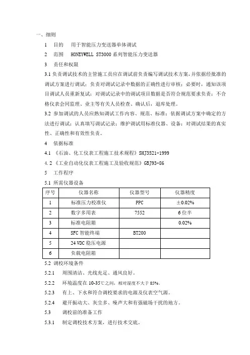
4依据标准4.1 《石油、化工仪表工程施工技术规程》SHJ3521-19994.2 《工业自动化仪表工程施工及验收规范》GBJ93-865工作程序5.1 所需仪器设备5.2 调校环境条件5.2.1 周围清洁、光线充足、通风良好。
5.2.2 环境温度在10-35℃之间,相对湿度不大于85%。
5.2.3 有上、下水和符合调校要求的电源及仪表空气源。
5.2.4 避开振动大、灰尘多、噪声大和有强磁场干扰的地方。
5.3 调校前的准备工作5.3.1 制定调校技术方案,进行技术交底。
5.3.2 熟悉仪表说明书、仪表规格书;掌握仪表性能及操作要求。
5.3.3 标准仪器要具备有效的检定合格证;基本误差的绝对值不应超过被校仪表基本误差绝对值的1/3。
5.4 调校方法5.4.1 外观检查5.4.1.1 铭牌及设备的型号、规格、材质、测量范围、显示部分、使用电源等技术条件应符合设计要求。
5.4.1.2 无变形、损伤、油漆脱落、零件丢失等缺陷;外形主要尺寸、连接尺寸符合设计要求5.4.1.3 端子、接头固定件等应完整;附件齐全。
5.4.1.4 合格证及检定证书齐备。
5.4.2 参数整定5.4.2.1 智能变送器的工作状态为数字通讯方式或模拟通讯方式;调校时将它设定在模拟通讯方式(便于监视输出电流)。
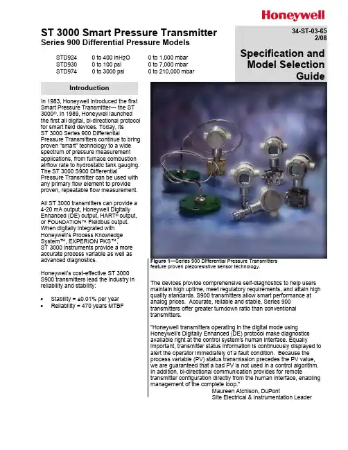
ST 3000 Smart Pressure TransmitterSeries 900 Differential Pressure ModelsSTD9240 to 400 inH 2O 0 to 1,000 mbar STD930 0 to 100 psi 0 to 7,000 mbarSTD974 0 to 3000 psi0 to 210,000 mbar34-ST-03-652/08Specification and Model SelectionGuideIn 1983, Honeywell introduced the first Smart Pressure Transmitter ― the ST 3000®. In 1989, Honeywell launched for smart field devices. Today, its ST 3000 Series 900 Differentialproven “smart” technology to a wide spectrum of pressure measurement applications, from furnace combustion airflow rate to hydrostatic tank gauging. The ST 3000 S900 DifferentialPressure Transmitter can be used with any primary flow element to provide proven, repeatable flow measurement.All ST 3000 transmitters can provide a 4-20 mA output, Honeywell DigitallyEnhanced (DE) output, HART ®output, or F OUNDATION™ Fieldbus output. When digitally integrated with Honeywell’s Process Knowledge System™, EXPERION PKS™,ST 3000 instruments provide a more accurate process variable as well as advanced diagnostics.Honeywell’s cost-effective ST 3000 S900 transmitters lead the industry in reliability and stability:• Stability = ±0.01% per year • Reliability = 470 years MTBFFigure 1—Series 900 Differential Pressure Transmitters feature proven piezoresistive sensor technology.The devices provide comprehensive self-diagnostics to help users maintain high uptime, meet regulatory requirements, and attain high quality standards. S900 transmitters allow smart performance at analog prices. Accurate, reliable and stable, Series 900 transmitters offer greater turndown ratio than conventional transmitters."Honeywell transmitters operating in the digital mode usingHoneywell's Digitally Enhanced (DE) protocol make diagnostics available right at the control system's human interface. Equallyimportant, transmitter status information is continuously displayed to alert the operator immediately of a fault condition. Because the process variable (PV) status transmission precedes the PV value, we are guaranteed that a bad PV is not used in a control algorithm. In addition, bi-directional communication provides for remotetransmitter configuration directly from the human interface, enabling management of the complete loop.”Maureen Atchison, DuPontSite Electrical & Instrumentation LeaderIntroduction34-ST-03-65Page 2DescriptionFeaturesThe ST 3000 transmitter can replace any 4 to 20 mA output transmitter in use today and operates over a standard two-wire system.The measuring means is a piezoresistive sensor, which actually contains three sensors in one. It contains a differential pressure sensor, a temperature sensor, and a static pressure sensor.Microprocessor-based electronics provide higher span-turndown ratio, improved temperature and pressure compensation, and improved accuracy.The transmitter’s meter body and electronics housing resist shock, vibration, corrosion, and moisture. The electronics housing contains a compartment for the single-board electronics, which is isolated from an integral junction box. The single-board electronics is replaceable and interchangeable with any other ST 3000 Series 100 or Series 900 model transmitter.Like other Honeywell transmitters, the ST 3000 features two-way communication and configuration capability between the operator and the transmitter through several Honeywell field-rated portable configuration devices, including the Smart Field Communicator (SFC) and the Multiple Communication Configurator (MC ToolKit). While both are made for in-field use, the MC Toolkit also can be ordered for use in intrinsically safe environments.The SCT 3000 Smartline® Configuration Toolkit provides an easy way to configure instruments using a personal computer. The toolkit enables configuration of devices before shipping or installation. The SCT 3000 can operate in the offline mode to configure an unlimited number of devices. The database can then be loaded down-line during commissioning. •Choice of linear or square root output conformity is asimple configuration selection. •Direct digital integration with Experion PKS and othercontrol systems provides localmeasurement accuracy to thesystem level without addingtypical A/D and D/A converterinaccuracies.•Unique piezoresistive sensor automatically compensatesinput for temperature andstatic pressure. Added “smart”features include configuringlower and upper rangevalues, simulating accurateanalog output, and selectingpreprogrammed engineeringunits for display.•Smart transmitter capabilities with local or remoteinterfacing means significantmanpower efficiencyimprovements incommissioning, start-up, andongoing maintenancefunctions.34-ST-03-65Page 3SpecificationsOperating Conditions – All ModelsParameterReference Condition (at zero static)Rated ConditionOperative LimitsTransportation andStorage°C °F °C °F °C °F °C °F Ambient Temperature25 ±1 77 ±2-40 to 85-40 to 185 -40 to 85 -40 to 185 -55 to 125-67 to 257Meter Body Temperature 25 ±177 ±2 -40 to 1101-40 to 2301-40 to 125-40 to 257 -55 to 125-67 to 257Humidity %RH10 to 55 0 to 100 0 to 100 0 to 100Vacuum Region - Minimum Pressure mmHg absolute inH 2O absolute Atmospheric Atmospheric25 132 (short term 2) 1 (short term 2)Supply Voltage, Current, and Load ResistanceVoltage Range: 10.8 to 42.4 Vdc at terminals Current Range: 3.0 to 21.8 mALoad Resistance: 0 to 1440 ohms (as shown in Figure 2)Maximum Allowable Working Pressure (MAWP) 4(ST 3000 products are rated to Maximum Allowable Working Pressure. MAWP depends on Approval Agency and transmitter materials of construction.)STD924, STD930, STD974 = 4500psi, 310 bar 3 Static Pressure Limit = Maximum Allowable Working Pressure (MAWP) = OverpressureLimit1 For CTFE fill fluid, the rating is –15 to 110°C (5 to 230°F) 2Short term equals 2 hours at 70°C (158°F) 3MAWP applies for temperature range –40 to 125°C. However Static Pressure Limit is de-rated to 3000 psi from -26 to -40°C. Use of graphite o-rings de-rates transmitter to 3625 psi. Use of Adapter with graphite o-rings de-rates transmitter to 3000 psi. 4Consult factory for MAWP of ST3000 transmitters with CSA approval.34-ST-03-65Page 4O/1000 mbar)Performance Under Rated Conditions* - Model STD924 (0 to 400 inH34-ST-03-655Page* Performance specifications are based on reference conditions of 25°C (77°F), zero (0) static pressure, 10 to 55% RH, and316L Stainless Steel barrier diaphragm.34-ST-03-65Page 6* Performance specifications are based on reference conditions of 25°C (77°F), zero (0) static pressure, 10 to 55% RH, and 316L Stainless Steel barrier diaphragm.34-ST-03-65Page7 Performance Under Rated Conditions - General for all ModelsParameter DescriptionOutput (two-wire) Analog 4 to 20 mA or DE digital communications mode. Options available forF OUNDATION Fieldbus and HART protocol.Supply Voltage Effect 0.005% span per volt.Damping Time Constant Adjustable from 0 to 32 seconds digital damping.CE Conformity (Europe) 89/336/EEC, Electromagnetic Compatibility (EMC) Directive.NAMUR NE 43 Compliance Option Transmitter failure information is generated when the measuring information is invalid or no longer present. Failure information is transmitted as a current signal but outside the normal 4-20 mA measurement signal level. Transmitter failure values are:≤ 3.6 mA and ≥ 21.0 mA. The normal signal range is ≥ 3.8 mA and ≤ 20.5 mA.SIL 2/3 Compliance SIL certified to IEC 61508 for non-redundant use in SIL 2 related Safety Systems(single use) and for redundant (multiple) use in SIL 3 Safety Systems throughTÜV Nord Sys Tec GmbH & Co. KG under the following standards:IEC61508-1: 1998; IEC 61508-2: 2000; IEC61508-3: 1998.Lightning Protection Option (Code “LP”) Leakage Current: 10 microamps max. @ 42.4 VDC, 93°CImpulse Rating: 10/20 µ sec. 5,000 Amps (50 strikes) 10,000 Amps (20 strikes) (rise/decay) 10/1000 µ sec. 250 Amps (1000 strikes) 500 Amps (400 strikes)Physical and Approval BodiesParameter DescriptionBarrier Diaphragms MaterialSTD924, STD930, STD974316L SS, Hastelloy C-276, Monel, Tantalum, Gold plated 316LSS, Gold platedHastelloy C-276, Gold plated MonelProcess Head MaterialSTD924, STD930, STD974316 SS, Carbon Steel (zinc-plated), Monel, HastelloyHead Gaskets Glass filled PTFE standard. Viton and graphite optional.Meter Body Bolting Carbon Steel (Zinc plated) standard. Options include 316 SS, NACE A286 SS boltswith NACE 304 SS nuts, and B7M.Optional Adapter Flange and Bolts Adapter Flange materials include 316 SS, Hastelloy C-276 and Monel. Options for bolting include carbon steel, 316SS, NACE A286SS and B7M. Standard adapter flange gasket material is glass filled PTFE. Viton and graphite optional.Mounting Bracket Carbon Steel (Zinc-plated) or Stainless Steel angle bracket or Carbon Steel flatbracket available (standard options).Fill Fluid Silicone DC 200 oil or CTFE (Chlorotrifluoroethylene)Electronic Housing Epoxy-Polyester hybrid paint. Low Copper-Aluminum. Meets NEMA 4X (watertight)and NEMA 7 (explosionproof). Stainless steel optional.Process Connections 1/4-inch NPT; 1/2-inch NPT with adapter. Process heads meet DIN 19213requirements.Wiring Accepts up to 16 AWG (1.5 mm diameter).Mounting Can be mounted in virtually any position using the standard mounting bracket. Bracketis designed to mount on 2-inch (50 mm) vertical or horizontal pipe. See Figure 3. Dimensions See Figure 4.Net Weight Approximately 9 pounds (4.1 Kg)34-ST-03-65Page 8Physical and Approval Bodies (continued)ParameterDescriptionApproval BodiesFactory MutualExplosion Proof: Approved as Explosion Proof for Class I, Division 1, Groups A, B, C, D locations,Dust Ignition Proof: Approved as Dust Ignition Proof for Class II, III, Division 1, Groups E, F, G locations,Intrincically Safe: Approved as Intrinsically Safe for for Class I, II, III, Division 1, Groups A, B, C, D, E, F, G locations.Nonincendive: Approved as Nonincendive for Class I, Division 2, Groups A, B, C, D locations.CSAExplosion Proof: Approved as Explosion Proof for Class I, Division 1, Groups B, C, D locations,Dust Ignition Proof: Approved as Dust Ignition Proof for Class II, III, Division 1, Groups E, F, G locations,Intrincically Safe: Approved as Intrinsically Safe for Class I, II, III, Division 1, Groups A, B, C, D, E, F, G locations.Canadian Registration Number (CRN)All ST 3000 model designs, except SATG19L, STG99L, STG170 and STG180 have been registered in all provinces and territories in Canada and are marked CRN:0F8914.5c.ATEXIntrinsically Safe, Zone 0/1: EEx ia IIC T4, T5, T6Flameproof/Zone 1: EEx d IIC T5, T6 (enclosure IP 66/67) Non-Sparking, Zone 2: EEx nA, IIC T6 (enclosure IP 66/67)Multiple Markings: Ex II 1 G: EEx ia IIC T4, T5, T6, Ex II 2 G: EExd IIC T5, T6Ex II 3 G: EEx nA, IIC T6 (Honeywell) (enclosure IP 66/67)SA (Australian) Intrinsically Safe: EX ia IIC T4Non-Sparking: Ex n IIC T6 (T4 with SM option) INMETRO (Brazil)Flame-Proof, Zone 1: EX d IIC T5Pressure Equipment Directive (97/23/EC)The ST 3000 pressure transmitters listed in this Specification have no pressurized internal volume or have a pressurized internal volume rated less than 1,000 bar(14,500 psig) and/or have a maximum volume of less than 0.1 liter. Therefore, these transmitters are either; not subject to the essential requirements of the directive 97/23/EC (PED, Annex 1) and shall not have the CE mark, or the manufacturer has the free choice of a module when the CE mark is required for pressures > 200 bar (2,900 psig).exceeding allowable pressure limits, (equipment with safety functions in accordance with Pressure Equipment Directive 97/23/EC article 1, 2.1.3), require separate examination.Figure 3—Examples of typical mounting positions34-ST-03-659PageFigure 4—Typical mounting dimensions for STD924, STD930 and STD974 for reference.34-ST-03-65Page 10Options Ordering InformationMounting BracketThe angle mounting bracket is available in either zinc-plated carbon steel or stainless steel and is suitable for horizontal or vertical mounting on a two inch (50 millimeter) pipe, as well as wall mounting. An optional flat mounting bracket is also available in carbon steel for two inch (50 millimeter) pipe mounting. Indicating Meter(Options ME and SM)Two integral meter options are available. An analog meter (option ME) is available with a 0 to 100% linear scale. The Smart Meter (option SM) provides an LCD display for both analog and digital output and can be configured to display pressure in pre-selected engineering units.Lightning Protection(Option LP)A terminal block is available with circuitry that protects the transmitter from transient surges induced by nearby lightning strikes.HART® Protocol Compatibility (Options HC and H6)Optional electronics modules for the ST 3000 that provides HART protocol compatibility in either the HART 5.x or 6.x formats. Transmitters with a HART option are compatible with any HART enabled system that provides either 5.x or 6.x format support.F OUNDATION Fieldbus(Option FF)Equips transmitter with FF protocol for use in 31.25 kbit/s FF networks. See document 34-ST-03-72 for additional information on ST 3000 Fieldbus transmitters. SIL2/SIL3 Certification(Option SL)This ST 3000 product is available for use with safety systems. With the SL option, we are fully certified to SIL 2 capability for single transmitters and SIL 3 capability for multiple transmitter use throughTÜV Nord Sys Tec GmbH & Co. KG. We are in compliance with thefollowing SIL standards:IEC 61508-1: 1998;IEC 61508-2: 2000;IEC 61508-3: 1998NAMUR NE43 Compliance(Option NE)This option provides software themeets the NAMUR NE43requirements for failsafe software.Transmitter failure information isgenerated when the measuringinformation is no longer valid.Transmitter failure values are:≤ 3.6 mA and ≥ 21.0 mA. Thenormal ST 3000 ranges are ≤ 3.8mA and ≥ 20.5 mA.Indicator Configuration(Option CI)Provides custom configuration ofSmart Meters.Tagging (Option TG)Up to 30 characters can be addedon the stainless steel nameplatemounted on the transmitter’selectronics housing at no extracost. Note that a separatenameplate on the meter bodycontains the serial number andbody-related data. A stainlesssteel wired on tag with additionaldata of up to 4 lines of 28characters is also available. Thenumber of characters for taggingincludes spaces.Transmitter Configuration(Option TC)The factory can configure thetransmitter linear/square rootextraction, damping time, LRV,URV and mode (analog/digital)and enter an ID tag of up to eightcharacters and scratchpadinformation as specified.Custom Calibration and ID inMemory (Option CC)The factory can calibrate anyrange within the scope of thetransmitter’s range and enter anID tag of up to eight characters inthe transmitter’s memory.Contact your nearest Honeywell salesoffice, orIn the U.S.:HoneywellIndustrial Automation & Control16404 North Black Canyon Hwy.Phoenix, AZ 850531-800-288-7491In Canada:The Honeywell Centre155 Gordon Baker Rd.North York, Ontario M2H 3N71-800-461-0013In Latin America:Honeywell Inc.480 Sawgrass Corporate Parkway,Suite 200Sunrise, FL 33325(954) 845-2600In Europe and Africa:Honeywell S. A.Avenue du Bourget 11140 Brussels, BelgiumIn Eastern Europe:Honeywell Praha,s.r.o. Budejovicka 1140 21 Prague 4,Czech RepublicIn the Middle East:Honeywell Middle East Ltd.Khalifa Street,Sheikh Faisal BuildingAbu Dhabi, U. A. E.In Asia:Honeywell Asia Pacific Inc.Honeywell Building,17 Changi Business Park Central 1Singapore 486073Republic of SingaporeIn the Pacific:Honeywell Pty Ltd.5 Thomas Holt DriveNorth Ryde NSW Australia 2113(61 2) 9353 7000In Japan:Honeywell K.K.14-6 Shibaura 1-chromeMinato-ku, Tokyo, Japan 105-0023Or, visit Honeywell on the World WideWeb at: Specifications are subject to changewithout notice. (Note thatspecifications may differ slightly fortransmitters manufactured beforeOctober 30, 1995.)Model Selection Guide (34-ST-16-24)Model Selection Guide34-ST-16-24 Issue 43Important Note:** Vent/Drains are Teflon coated for lubricity.* Carbon Steel heads are zinc-plated and not recommended for water service due to hydrogen migration. For that service, use 316 stainless steel wetted Process Heads.Base STD models no longer include a default communications option. All units now require the selection of a communication option from Table III (AN, DE, HC, H6 or FF).AvailabilityTable III continued next pageAvailabilityEnclosure IP 66/67(Honeywell). Enclosure IP 66/67** The user must determine the type of protection required for installation of the equipment. The user shall then check the box [√] adjacent to the type of protection used on the equipment certification nameplate. Once a type of protection has been checked on the nameplate, subsequently the equipment shall not be reinstalled using any of the other certification types.Note:See ST-83 for Published Specials with pricing.See ST-89 and User's Manual for part numbers.See ST-OE-9 for OMS Order Entry Information including TC, manuals, certificates, drawings and SPINS.See ST-OD-1 for tagging, ID, Transmitter Configuration (TC) and calibration including factory default values.To request a quotation for a non-published "special", fax RFQ to Marketing ApplicationsST 3000® is a registered trademark of Honeywell International Inc.HART is a registered trademark of the Hart Communication Foundation.FOUNDATION ™ is a trademark of the Fieldbus Foundation.Honeywell Process SolutionsIndustrial Measurement and ControlHoneywell International Inc. 2500 W. Union Hill Drive Phoenix, Arizona 85027©Honeywell International Inc.。

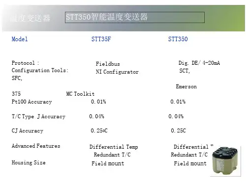
STT 3000 Series STT250Smart Temperature Transmitters Specifications Models STT25TEN0l-6091 March 2010IntroductionHoneywell’s STT 3000 family of microprocessor based transmitters covers the full spectrum of temperature measurement. Choose the top-tier STT350 for super Smart performance transmitters, the STT250 for competitive performance in a compact head mount package, or the low-tier PC configurable STT150 for fit-and-forget applications. See Product Specification Sheets :• EN0I-5222 for STT350• EN0I-6031 for STT250 (models STT25M/ H/ D) • EN0I-6063 for STT150 (models STT15R/ U/ S ) This Product Specification Sheet describes the latest addition to the STT250 range – the dual input STT25T targeted to provide secure/ redundant measurement and reduced maintenance costs by auto sensor self checking.DescriptionThe STT25T can accept two independent temperature sensor inputs – either Pt100 or thermocouples Types J, K, T or E. The primary sensor is used to drive the 4-20mA output, while the secondary sensor can be used as a redundant back-up in case the primary sensor fails, or can be used for cross-checking the stability of the primary sensor.The STT25T supports the HART* communications protocol for ease of configuration and maintenance checking of sensor integrity via any of the listed HART Communication Foundation tools.The transmitter is 2-wire powered and gives an output 4-20mA signal linearized to temperature over the 2 power wires. Lead wire compensation is provided for RTD (Resistance Temperature Detectors) and internal digital cold junction compensation is provided for thermocouples. MilliVolt and Ohms sensor inputs can also be accepted.Features• Direct sensor head mounting in DIN Form A housing.Housing materials include aluminum, 316SS and cast iron.• Mounting options include wall, pipe, DIN rail, field ordirect sensor head mounting.• Single model accepts input signals from two RTD orthermocouple or mixed sensor types Pt100, J, K, T or E.• Suitable for 3- or 2-wire Pt100.• Hard-wired upscale/ downscale failsafe link to ensuresecure operation in the event of a failure. • Open circuit sensor analysis carried out in everymeasurement cycle.• Selectable latching/non-latching failsafe operation foropen circuit sensor.• Integral analog or digital indication meter option. • Analog to Digital converter validated frequently. • Configuration adjustments and diagnostics checkscan be made either locally or remotely over the signal wires from anywhere along their route. This enables major savings in manpower time during commissioning, start-up and maintenance activities.Use the MC Toolkit Configurator, the HART hand-held communicator, or HART PC tool to configure the transmitter for any of these sensors/ applications.Accuracies stated overleaf are available merely by selecting the sensor type and range (i.e., without user calibration). Calibration of the LRV/URV end points typically will give accuracy improvements of two times. Sensor errors can be calibrated out by calibrating to the specific sensor either by having it at the LRV/URV temperatures or by simulation of the known values.In addition, all units pass through Environmental Stress Screening by fast cycling between -40°C and +85°C to ensure maximum product reliability. During this process the ambient temperature coefficients are determined for each unit and burned into memory to ensure temperature compensation over a wide range of operating conditions.HART* is a trademark of the HART Communication Foundation.Performance Under Rated ConditionsSensor Digital Accuracy over NormalRange°C (°F)D/AAccuracy% ofspanDigital Accuracy overMaximum Range°C (°F)Standards(All IEC referenced sensors usethe ITS-90 temperature scale)Pt100 0.15C for -200 to 450 (-328 to 842) 0.025%0.25C for -200 to 850C (-328 to 1562) IEC 60751 (α=0.00385) E 0.30C for 0 to 1000 (32 to 1832) 0.025%0.60C for -200 to 1,000C (-328 to 1832) IEC 60584-1J 0.30C for 0 to 800 (32 to 1472) 0.025%0.70C for -200 to 1,200C (-328 to 2192) IEC 60584-1K 0.60C for -120 to 1370 (-191 to 2498) 0.025%0.90C for -200 to 1370C (-328 to 2498) IEC 60584-1T 0.30C for -100 to 400 (-148 to 752) 0.025%0.5C for -250 to 400C (-418 to 752) IEC 60584-1SpecificationsOperating ConditionsParameter Reference Condition Rated Condition Operative Limits Transportation AndStorage Ambient temperature °C 23 °C ± 2 -40 to +85 -40 to +85 -50 to +100 HumidityRack mounted % RH 10 to 55 5 to 95 5 to 100 5 to 100In field housing % RH 10 to 55 5 to 100 5 to 100 5 to 100 Supply voltage Voltage range 10.8 to 35 Vdc at the transmitter terminalsOutput current Current overrange 3.8 to 20.8 mA. Failsafe limits < 3.8 and 21.8 mALoad resistance 0 to 1110ΩVibration Maximum of 4g over 15 to 200Hz (restricted to 3g with indication meter).Shock Maximum of 40g.Performance SpecificationsOutput D/A accuracy: ±0.025% of spanCold Junction accuracy: ±0.5°CTotal reference accuracy: Analogue 4-20mA mode = Digital accuracy + Output D/A accuracy + CJ accuracy (T/Cs only)Total reference accuracy: Digital DE mode = Digital accuracy + CJ accuracy (T/Cs only).(example: transmitter operating in analogue mode with Pt100 sensor and 0 to 200°C range.Total reference accuracy =0.15+(200/100)*0.025 = 0.2°C.Digital ambient temperature effect (per 10°C change from 23°C ref.): RTDs or Ohms : 0.050% of reading in Ohms. : T/Cs or mV : 0.080% of reading in mV.Output D/A ambient temp. effect (per 10°C change from 23°C ref.): ±0.045% of span.Cold Junction ambient temperature effect: 40: 1 rejection for ambient temperature changes from 23°C reference.Total Reference Accuracy (Reference – Includes combined effects of linearity, hysteresis, and repeatability) Total output ambient temperatureeffect : Analogue 4-20mA mode =Digital effect + Output D/A effect + CJeffect (T/Cs only).Total output ambient temperatureeffect: Digital DE mA mode = Digitaleffect + CJ effect (T/Cs only).Power supply voltage effect: 0.005%of Max span per Volt.Stability/time drift: 0.05% of max spanper year.Additional ParametersOutput: 4-20mA or Honeywell digitalDE protocol. HART and DE availablewith 4-20mA output.Adjustment range: No limits toadjustments within the MaximumRange except minimum span limit of 1engineering unit e.g. 1°CDamping time constant: Adjustablefrom 0 to 102 seconds digitaldamping.Output response time:1 second to reach 63% of final valuewith 0 secs damping.Output update time0.5 secs approximately.Input/ output galvanic isolationWithstands 500Vac dielectric strengthtest for 1 minute.Sensor open circuitOpen circuit/ burnout detection is userselectable. Upscale or downscale withcritical status message. Latching ornon-latching sensor burnout action.Common mode rejection120dB (1 million to 1) from 50Hz to50 kHz.Series mode rejection40dB (100 to 1) for 50 or 60Hz±0.5Hz. (with internal software filterset to local power line frequency).EMC complianceIn compliance with2004/108/EC,Electromagnetic Compatibility (EMC)Directive.Radiated RF Immunity: ±0.15% ofspan at 10V/m over 80 to 1,000MHz.Physical Mounting and ConstructionThe STT250 Temperature Transmitter is designed to be mounted in a DIN Form A housing for direct installation with the temperature sensor or can be provided in a remote pipe or wall mount housing. Details for the various housings available are referenced in the table below. The STT250 Temperature Transmitter module can also be DIN rail mounted to a top hat or “G” rail via a clip. Integral meters availableIntegral MetersHoneywell’s Series STT250 Temperature Transmitters can be supplied with local or remote indication. An Analogue, Engineering Units or a Smart meter can be mounted integral to the transmitter inside the field mount housing. Order an integral meter as part of the model number; Table II _ _ M, _ _ E and _ _ S, respectively. Order a remote meter as model RMA300. The analogue meter is a 4-20mA moving coil type and displays the temperature in 0 to 100% span.The E. U. meter displays temperature in engineering units with the STT25H, STT25T and STT25S HART units. Refer to 34-ST-25-08D for more details. The Smart meter accepts 4-20mA or DE protocol and displays temperature on a LCD in engineering units or 0 to 100% span.The remote digital meter reads DE protocol and displays temperature on a LCD in 0 to 100% span. Refer to 34-ST-25-07A for details.STT250 Module Dimensions (in/mm)55233STT250 ConnectionsMaterials of ConstructionTerminal Block NorylConnection Screws M3 Nickel plated brassModule Housing Cycoloy (PC/ABS) with metallized interior surfaceWeight 0.075 kg (0.2 lbs)ApprovalsThe STT250 Temperature Transmitter module is Intrinsically Safe to ATEX, IECEx , SAEx, FM and CSA standards when used with a suitable safety barrier. It is zone 2 and explosion-proof to ATEX, IECEx, SAEx, FM and CSA standards when installed in a suitable housing. See the Model Selection Guide Table VII in this Specification Sheet for detailed safety approvals covering both the STT250 module only or for the STT250 module supplied in a housing.Probe and Thermo well AvailabilitySTT250 can be supplied complete with a wide range of thermo wells, thermocouples or RTD sensors. See documents listed in the table below.The range of thermo wells available as a total thermal solution cover almost every possible requirement :STT820 Series 34-44-16-08 Rigid Probe Assemblies.STT830 Series 34-44-16-09 Threaded and Socket Weld Thermo well Assemblies with Transmitter Option.STT840 Series 34-44-16-10 Drilled Flange Thermo well AssembliesModel Selection Guides are subject to change and are inserted into the specifications as guidance only.Prior to specifying or ordering a model check for the latest revision Model Selection Guides which are published at: /Cultures/en-US/Products/Instrumentation/ProductModelSelectionGuides/default.htm Model Selection GuideThis page has been intentionally left blankFor More InformationLearn more about how Honeywell’s STT3000 Smart Temperature Transmitters can increase performance, reduce downtime and decrease configuration costs, visit our website /ps or contact your Honeywell account manager.Automation & Control Solutions Process SolutionsHoneywell2500 W. Union Hills Dr. Phoenix, AZ 85027Tel: 877.466.3993 or 602.313.6665 /psEN0l-6091March 2010© 2008-10 Honeywell International Inc.。

PA/V A SOLUTIONSVARIODYN D1Digital Public Address andVoice Alarm System2 | Voice Alarm is increasingly important in the safe management of buildings. A voice message informs occupants exactly what to do in an emergency and it is a long established fact that people respond more quickly and are more likely to take the correct action during an evacuation if voice messages are used instead of tone sounders.THE ROLE OF VOICE ALARM• Clear directions to people in the building• Live messages giving exactinstructions to people whoare not familiar with the surroundings • Customised pre-recordedmessages (available inmultiple languages)• Up to 20 minutes shorter response time to fire alarm• Serial Interface toHoneywell fire panels for EVAC guidance and time-controlled evacuation • High-end non-emergency features such asequalizing, automatic volume control and multi-channel announcements as well as backgroundmusic • Alarm cancellation and manual evacuation override controlBENEFITS | 3PUBLIC ADDRESS -MORE THAN VOICE ALARMVoice Alarm systems are more frequently used as public address and entertainment systems than only as automatic evacuation system inpublic buildings with a high number of visitors.• Paging and evacuation with zone-dependent messages • Integration with airport/train station managementsystems• Multiple channel/zone music broadcasting • Sport/concert hall and stadium sound systemintegration • Time-scheduled announcements• Touch screen operation panels• Operation from intuitive computer management systems • High quality background music for high class shopping experienceFEATURES PUBLIC ADDRESS PROVIDES ADDITIONALL Y:4 |Selecting, designing and commissioning a PA/VA system can be challenging. At Honeywell we have a team of experts that will help you build the most suitable system for your building.The first step is to decide exactly what type of PA/VA system you will need. This will largely depend on the size and functional complexity of your building.The following two types of systems are available that start from small ‘Compact Solution’ packages suitable for single storey buildings such as shops and offices and move up to a custommade ‘Modular System’ that will consist of a number of distributed systems linked together for large structures such as exhibition fairgrounds and airports.VOICE ALARMCOMPETENCE FOR YOU• Controlling and indicating equipment certified to EN 54-16 and EN 54-4• Complete range of EN 54-24 certified loudspeakers • Flexible systems that supports both simple and the most complex communication needs • High quality digital audio matrix• Intuitive touchscreen Graphical User Interface that manages the entire system • Phased evacuation scenarios • Situation, location & evacuation phasedependent voice messages • Exact guidance regarding evacuation routes• Freely configurableevacuation scenarios with logical dependencies • Dedicated Honeywelldesign and project supportSYSTEMS KEY FEATURES |5 LEISURE COMPLEXES SCHOOLS SMALL HOTELS OFFICESTHE COMPACT SOLUTION:COMPRIO D1An easy-to-install PA/VA system.Suitable for small to medium buildingswith up to 24 loudspeaker zones.APPLICATIONS• Leisure complexes• Supermarkets• Schools• Hotels• OfficesBENEFITS• Amplifier with build-in PSU available• ‘Off the Shelf’ Package• Installation within two hours• Only 8 HU rack space incl. amplifier,charger and batteries• Ensured compliance to ENstandards• Complete solution for up to 24zones• max. 2000 W output powerexpandable with additional DOM/AMPs6 | Our PA/VA systems can be distributed and networked together to deliver the most comprehensive and powerful solution for a wide range of applications. Suitable for mid to large and complex sites.THE MODULAR SOLUTION V ARIODYN D1• Industrial facilities • Universities• Airports and transport hubs • Stadiums• Exhibition halls and fairgrounds • Mega Shopping Malls • Large Office buildingsAPPLICATIONS• Scalable and modular to adapt to constant changes and demands• Supports a large number of evacuation and/or paging zones • Manages complicated evacuation strategies in the event of an emergency • IP connectivity tolink multiple nodes (VARIODYN D1 DOM)BENEFITS• Up to 120 announcements at the same time• Pre-recording and playbackof messages• Secured data link to various Honeywell Fire Alarm Systems• Decentralized and redundant system architecture• Interface to BuildingManagement Systems (e.g. Honeywell EBI)• Redundant network and Call Stations linksComputer Management Station (PAMMI)Decentralized | 7STADIUMS AIRPORTS SHOPPING MALLS RAILWAY STATIONSCUSTOMISED CONTROLThe PAMMI (Public Announcement Man Machine Interface) software provides monitoring and control of the Honeywell Voice Alarm System via a graphical user interface on a Microsoft Windows® based personal computer.PERFECT SYMBIOSIS VOICE ALARM AND FIRE ALARMAREA BY AREA, TARGETED AND ORDERL Y:EVACUATION PROCEDURE EXAMPLE AT THE AIRPORT• There is a short-circuit in the baggage sortingarea on the 1st sub-level,section B of the airport. • The fire detector detects the formation of smokeand transmits theinformation to the firealarm control panel.• The fire alarm system simultaneously initiatesalarms to the securityservices and the voicealarm system.• The security inspectorassesses the situation viathe video camera installedon-site and then activatesa stored a nnouncementto the personnel with thepush of a button.• Due to the increasingformation of smoke,the fire alarm systemautomatically closes thefire door in the affectedarea.Synergies arise through digital coupling of the fire alarm system with the voice alarm system, thus facilitating an orderly, area-specific evacuation during emergencies: If a fire is detected by the connected fire detectors and then received by the fire alarm control panel, this automatically activates the voice alarm system. The endangered areas are then selected automatically and informed via the PA/VA system, while at the same time the fire alarm control panel activates fire protection systems, for example, fire doors, air-conditioning and ventilating systems, elevator controls or smoke dampers.The combination of voice alarm and fire alarm technology not only offers functional advantages, there are economical advantages as well: PA/VA reduces the total EVAC time significantly, a PA/VA system is not much more expensive than standard sounders, while it adds valuable support by increasing productivity of building occupants.8 | | 9VARIODYN D1 AND COMPRIO PA/VA SYSTEM DIAGRAM Thanks to its modular construction and the varioussystem components, the VARIODYN D1 system can easily DCS Digital Call Station DSCF DSC for Firefighter Fire Alarm Control PanelInterfaceDOMAMP PSUDCSF 1/12Configuration via LaptopCD playerETCSDCS PlusCentral Operating Terminal(PAMMI, WINMAG, Honeywell EBI etc)Loop Isolator ModuleAdvanced,Automatic Volume Control10 | WINMAGPLUSONE MANAGEMENT SYSTEM FOR ALLPERFORMANCE FEATURES OF THE VARIODYN D1 INTERFACE WINMAGPLUS DRIVER• System configuration readout of a VARIODYN D1 network to take it over via import files to WINMAGplus application.• Fault and status indication of the VARIODYN D1 system components: • DOM, SCU, DAL bus devices like DCS and • UIM, Amplifiers (each channel)• Audio and control contact inputs and outputsThe WINMAGplus hazard management system lets you create a scalable software solution with superb levels of integration with different sub-systems.In case of Voice Alarm system, VARIODYN D1 is connected via Ethernet/RJ45 to the same network as the WINMAGplus server. This enables the VARIODYN D1 integration with systems such as: fire alarm, fire extinguishing, smoke and heat control, escape routes, CCTV, access control, intrusion detection, emergency lighting as well as BMS and others via open protocols.• Call station function: • Microphone switched to pre-selectable or fixed targets for live-spoken announcements• Playback of pre-recorded announcements onselectable or fixed targets• Display, update and controlof: • Volume• Volume presettings (min., max., alarm)• Audio signal levels • Control contacts | 11Client Ma chinesHazardManagementVideo SystemsIntrusion Detection SystemsAccess ControlPublic Address & Voice AlarmFire AlarmFireExtinguishingFireControlsEmergency LightingBuildingManagement Systems12 | CHALLENGING PROJECTS REQUIRE BEST DESIGN AND EXPERTISEBY CEN/TS 54-32 EUROPEAN STANDARD VA SYSTEM CAN BE DESIGNED IN 2 WAYS TO ACHIEVE REQUIRED INTELLIGIBILITY: 1. Simplified, prescriptive method, requiring loudspeakers mounted every 6 meters or less.2. Detailed method, requiring in practice acoustics simulations as VA system design base regarding spacing, location, type selection, audio equalizing and proper orientation of loudspeakers.Acoustic simulations are paramount for a proper PA/VA system design in complex, tough and large areas. EN 50489 and CEN/TS 54-32 require minimum intelligibility level from installed VA systems. Installing and planning VA systems bears a risk of failure during intelligibily measurements in the handover phase. Toprevent such critical situations and underbudgeting of VA systems acoustic simulations are the only guarantee. |13EXAMPLE OF THE ACOUSTIC SIMULATION OF AN AUDITORIUM Acoustic simulation software provides to precisely and reliably assess sound pressure level (dB) and intelligibility level (STI/CIS). The software calculates the simulatedroom as a space map in 3D, enabling the user to verify the selected type, location and setting of loudspeakers.Voice Alarm system design for acoustically challenging areas must be based on professional, quality simulations,prepared by experienced acoustic experts.Our Technical Support Team provides expertise, experience, tools and wide portfolio of certified VA loudspeakers to assure our partners and system designers that Variodyn D1 system designs will pass acceptance tests.14 | VARIODYN D1 PRODUCT FAMIL YAll of the components of the VARIODYN D1 product family are compatible, interchangeable and optimally adapted to the customers growing needs. As varied as the requirements may be, all of the components are modular designed andcan be combined with each other quick and easy.ComprioComprio is a voice alarm system optimised for small and medium-size facilities such as schools,hotels, leisure centres and offices. It's characterised by its compact design, wide performance range and its flexibility.Digital Output Module (DOM)The Digital Output Module (DOM) is the heart of the Honeywell Voice Alarm and Public Address system. Managing either 8 or 24 zones the DOM routes up to 4 channels of audio from amplifiers to any individual zone or group of zones.Class D Power AmplifiersCombining the latest in digitalaudio technology with the integrity necessary for emergency Voice Alarm systems to satisfy the requirements of EN54 part 16.Direct Drive Power Amplifier4-channel Direct Drive Amplifier 4 x 300 W or 4 x 500 W power outputs or unit providing 4 x 125 W or 4 x 250 W power outputs with integral EN 54-4 certified battery charger.Paging Microphone DCSPlus The paging microphone allows for the selection of loudspeakerzones, and the transmission of voice announcements via programmable buttons.Ethernet Touch Call Station (ETCS)This EN 54-16 certified touch screen call station provides a user friendly, multilingual and multi-user interface support with high failure safety due to redundant transmission routes via Ethernet (PoE possible). It includes audio memory up to 27 hour and a USB stick can be connected to play audio files as well.Universal Interface Module (UIM)Interface module enables audio or control connection to third party systems such as CD players, security systems and other PA/VA or building management control systems.System Communication Unit (SCU)The System Communication Unit (SCU) is an integrated digital audio memory source able to simultaneously record and play back multiple audio data streams.PAMMI PublicAnnouncement User Interface The PAMMI software provides connection and control of the Honeywell Voice Alarm System via a graphical user interface on a Microsoft Windows ® based PC.Emergency Microphones Emergency Microphone used to select and broadcast pre-programmed alarm messages and live voice announcements during emergency situations by security operator or fire brigade commander. | 15LOUDSPEAKERSHoneywell offers loudspeakers, specially designed to meet various requirements and specifications in many project types e.g.Excellent acoustic performance to realize clear, understandable voice announcements or high quality background music.• Cost-effective types• Well designed, modern appearance• Easy for installation to reduce time, efforts and costs • Robust material to offer long lifetime•Models with ceramic terminal block and thermofuseCeiling Loudspeaker• Metal or plastic ceilingloudspeakers• Several power tappings withsimple setting• Partly dual-cone speaker toensure best audio performance • Appropriate for indoorapplications such as offices, warehouses, schools etcHorn Speaker• Clear voice messagereproduction for open and outside areas• Offers a high sound pressureand long-lasting weather resistanceSound Projector• Wide frequency response range,low distortion• Robust aluminum housing • IP65 rating• Best option for applicationssuch as corridors and railway platformsColumn Loudspeaker • Flat, directed soundpropagation, minimized reverberation• Intelligible voice and superiorsound reproduction • IP65 rating• Great choice for theme parks ,exhibition halls and any open, high-volume rooms with high reverberation time.Cabinet Loudspeaker• Simple power setting and easyinstallation• Practicable for wall mountapplication• Plastic, MDF or metal vandal-proof cabinetSpherical Loudspeaker• Where wall mount or ceilingmounting is not possible • Variable hanging height • 360° sound propagationSpecial Loudspeaker for tunnels• Specially designed and EN 54-24certified for tunnel applications • Boundary effect and loudspeakerphasing for best intelligibility inextremely difficult tunnel projectsEXTRACT FROM OUR EXTENSIVE PRODUCT OFFERINGS:00-0000 | DI | 01/ 21© 2021 Honeywell International Inc.Honeywell Building Technologies 715 Peachtree St. NE Atlanta, GA 。
ST 3000 Smart TransmitterSeries 100 High Temperature GP ModelsSTG14T, STF14T 0-500 psig / 0-35 barg34-ST-03-707/04Specification and Model SelectionGuideIn 1983, Honeywell introduced the first Smart Pressure Transmitter ― the ST 3000®. In 1989, Honeywell launched for smart field devices. Today, Honey-well transmitters demonstrate proven reliability in hundreds on installations in a wide variety of industries and applica-tions. For applications requiring direct connection to processes requiring small flange, small sanitary connec-tions or 1/2” NPT, Honeywell offers the STG14T transmitter. Applications in-clude gauge pressure for reaction ves-sels in the chemical industry as well as level applications in both the chemical and hydrocarbon processing industries with a relatively high process tempera-ture of 302F (150C). Applications for the food and pharmaceutical industries typically use sanitary connections and M-20 fill fluid.All ST 3000 transmitters can provide a 4-20 mA output, Honeywell Digitally Enhanced (DE) output, HART * output, or F OUNDATION ™ Fieldbus output. When digitally integrated with Honey-well’s Process Knowledge System™, EXPERION PKS™, ST 3000 instru-ments provide a more accurate proc-ess variable as well as advanced diag-nostics.S100 transmitters lead the industry in: • Accuracy • Stability • Reliability • Rangeability • WarrantyIncludes Lifetime Tranmsitters: • Accuracy = +/-0.0375%• Stability = +/-0.01% per year • Reliability = 470 years MTBF • Rangeability = 400 to 1• Lifetime Warranty = 15 yearsFigure 1—Series 100 High Temperature GP Transmitters feature proven pie-zoresistive sensor technology.The devices provide comprehensive self-diagnostics to help users maintain high uptime, meet regulatory requirements, and attain high quality standards. S100 transmitters are ideal for critical applications, such as custody transfer of natural gas and energy and material bal-ances, where accuracy and stability are of the utmost importance."Our commitment to Honeywell field instruments is based on seam-less integration with our Honeywell system and the enhanced fault detection that the Honeywell DE protocol offers. Honeywell instru-ments also offer us a better way of ensuring database integrity over simple analog instruments. In addition, Honeywell's high-quality sup-port has enabled us to better implement solutions to some of ourmore difficult problems. We have used Honeywell differential pressure smart transmitters for the past eight years. Based on their accuracy and low failure rates, we are now targeting critical flow applications that require the robustness that these transmitters bring.” DCS Systems EngineerInternational Integrated Oil CompanyIntroduction34-ST-03-70 Page 2Description FeaturesThe ST 3000 transmitter can replace any 4 to 20 mA output transmitter in use today and operates over a standard two-wire system.The measuring means is a piezoresistive sensor, which actually contains three sensors in one. It contains a differential pressure sensor, a temperature sensor, and a static pressure sensor.Microprocessor-based electronics provide higher span-turndown ratio, improved temperature and pressure compensation, and improved accu-racy.The transmitter’s meter body and electronics housing resist shock, vibra-tion, corrosion, and moisture. The electronics housing contains a com-partment for the single-board electronics, which is isolated from an inte-gral junction box. The single-board electronics is replaceable and inter-changeable with any other ST 3000 Series 100 or Series 900 model transmitter.Like other Honeywell transmitters, the ST 3000 features two-way com-munication between the operator and the transmitter through our Smart Field Configurator (SFC). You can connect the SFC anywhere that you can access the transmitter signal lines.The SCT 3000 Smartline® Configuration Toolkit provides an easy way to configure instruments using a personal computer. The toolkit enables configuration of devices before shipping or installation. The SCT 3000 can operate in the offline mode to configure an unlimited number of de-vices. The database can then be loaded downline during commissioning. • Choice of linear or square root output conformity is asimple configuration selec-tion.• Direct digital integration with Experion PKS and other con-trol systems provides localmeasurement accuracy to thesystem level without addingtypical A/D and D/A converterinaccuracies.• Unique piezoresistive sensor automatically compensatesinput for temperature andstatic pressure.Added “smart”features include configuringlower and upper range val-ues, simulating accurate ana-log output, and selecting pre-programmed engineeringunits for display.• Smart transmitter capabilities with local or remote interfac-ing means significant man-power efficiency improve-ments in commissioning,start-up, and ongoing mainte-nance functions.34-ST-03-70 Page 334-ST-03-70 Page 4Specifications34-ST-03-70Page 5Ambient Temperature De-ratingSilicone Fill Fluid Neobee Fill FluidProcess temperatures above 125 °C (257 °F) require de-rating the ambient limit as follows:Process temperatures above 85 °C (185 °F) require de-rating the ambient limit as follows:Process Temperature Ambient TemperatureLimit Process Temperature Ambient TemperatureLimit150 °C (302 °F) 140 °C (284 °F) 125 °C (257 °F)50 °C (122 °F)60 °C (140 °F)85 °C (185 °F)110 °C (230 °F)100 °C (212 °F)85 °C (185 °F)50 °C (122 °F)60 °C (140 °F)75 °C (167 °F)Performance Under Rated Conditions* -* Performance specifications are based on reference conditions of 25°C (77°F), 10 to 55% RH, and 316L SS diaphragm. ** Transmitter URL limit or maximum process connection rating, whichever is lower.34-ST-03-70Page 6Performance Under Rated Conditions – General for all ModelsParameter Description Output (two-wire) Analog 4 to 20 mA or digital communications DE mode. Options available forF OUNDATION Fieldbus and HART protocol.Supply Voltage Effect ±0.005% span per volt.Damping Time Constant Adjustable from 0 to 32 seconds digital damping.EMC Classification Group 1, Class A, ISM Equipment (EN 55011, emissions), Industrial Equipment (EN50082-2, immunity)CE Conformity (Europe) 89/336/EEC, Electromagnetic Compatibility (EMC) Directive.Lightning Protection Option (Code “LP”) Leakage Current: ***********************,93°CImpulse Rating: 10/20 µ sec. 5,000 Amps (50 strikes) 10,000 Amps (20 strikes) (rise/decay) 10/1000 µ sec. 250 Amps (1000 strikes) 500 Amps (400 strikes)Physical and Approval BodiesParameter Description Process Interface See Model Selection Guide for Material Options for desired process connection.Diaphragm Materials (wetted) 316L Stainless SteelGasket Ring Materials (wetted) 316L Stainless SteelMounting Flange (non-wetted) 316 Stainless Steel.Fill Fluid Silicone (DC 200) or Neobee (M20)Electronic Housing Epoxy-Polyester hybrid paint. Low copper-aluminum alloy. Meets NEMA type 4X(watertight) and designed to meet NEMA 7 (explosion proof).Process Connections Process Head: 1/2-inch NPT.Sanitary: 2” Sanitary Tri-Clamp.Flange: 1/2”, 1”, 1 1/2” and 2” 150# or 300# ANSI flange.Wiring Accepts up to 16 AWG (1.5 mm diameter).Mounting 1/2-inch NPT, sanitary seal, or flange mount connection.Dimensions See Figures 4 to 6Net Weight 7 pounds (3.2 Kg) to 15 pounds (7 Kg)Approval Bodies- Hazardous Areas- Canadian RegistrationNumber (CRN) Approved as explosion proof and intrinsically safe for use in Class I, Division 1, Groups A, B, C, D locations, and nonincendive for Class I, Division 2, Groups A, B, C, D locations. Approved EEx ia IIC T4, T5, T6 and EEx d IIC T5, T6 per ATEX standards. See attached Model Selection Guide for options.- All ST 3000 model designs, except STG19L, STG99L, STG170, STG180, have been registered in all provinces and territories in Canada and are marked CRN: 0F8914.5C.Table continued on next page ⇒34-ST-03-70Page 7Physical and Approval Bodies, continuedParameter DescriptionPressure Equipment Directive (97/23/EC) The ST 3000 pressure transmitters listed in this Specification have no pressurized internal volume or have a pressurized internal volume rated less than 1,000 bar (14,500 psig) and/or have a maximum volume of less than 0.1 liter. Therefore, these transmitters are either; not subject to the essential requirements of the directive97/23/EC (PED, Annex 1) and shall not have the CE mark, or the manufacturer has the free choice of a module when the CE mark is required for pressures > 200 bar (2,900 psig).NOTE: Pressure transmitters that are part of safety equipment for the protection of piping (systems) or vessel(s) from exceeding allowable pressure limits, (equipment with safety functions in accordance with Pressure Equipment Directive 97/23/EC article 1, 2.1.3), require separate examination.Figure 4 Typical mounting dimensions for 1/2-inch NPT connection models for reference.34-ST-03-70 Page 8Figure 5 Typical mounting dimensions for flush sanitary seal connection models for reference.34-ST-03-70Page 9Figure 6 Typical mounting dimensions for small flange connection models for reference.34-ST-03-70 Page 10Options Ordering Information Indicating Meter(ME and SM Options)Two integral meter options are available. An analog meter (option ME) is available with a 0 to 100% linear scale. The Smart Meter (option SM) provides an LCD display for both analog and digital output and can be configured to display pressure in pre-selected engineering units.Lightning Protection (Option LP)A terminal block is available with circuitry that protects the transmitter from transient surges induced by nearby lightning strikes.HART Protocol Compatibility (Option HC)An optional electronics module is available for the ST 3000 that provides HART Protocol compatibility. Transmitters with the HART Option are compatible with the AMS System. (Contact your AMS Supplier if an upgrade is required.)Transmitter Configuration (Option TC)The factory can configure the transmitter linear/square root extraction, damping time, LRV, URV and mode (analog/digital) and enter an ID tag of up to eight characters and scratchpad information as specified. Lifetime Warranty(Option WL)Extends limited 1-year warranty policy to 15 years for ST 3000S100 pressure transmitters. See Honeywell Terms and Conditions.Indicator Configuration(Option CI)Provides custom configuration ofSmart MetersTagging (Option TG)Up to 30 characters can be addedon the stainless steel nameplatemounted on the transmitter’selectronics housing at no extra cost.Note that a separate nameplate onthe meter body contains the serialnumber and body-related data. Astainless steel wired on tag withadditional data of up to 4 lines of 28characters is also available. Thenumber of characters for taggingincludes spaces.Custom Calibration and ID inMemory (Option CC)The factory can calibrate any rangewithin the scope of the transmitter’srange and enter an ID tag of up toeight characters in the transmitter’smemory.F OUNDATION Fieldbus(Option FF)Equips transmitter with FF protocolfor use in 31.25 kbit/s FF networks.See document 34-ST-03-72 foradditional information on ST 3000Fieldbus transmitters.Contact your nearest Honeywell sales office,orIn the U.S.:HoneywellIndustrial Automation & Control16404 North Black Canyon Hwy.Phoenix, AZ 850531-800-288-7491In Canada:The Honeywell Centre155 Gordon Baker Rd.North York, Ontario M2H 3N71-800-461-0013In Latin America:Honeywell Inc.480 Sawgrass Corporate Parkway,Suite 200Sunrise, FL 33325(954) 845-2600In Europe and Africa:Honeywell S. A.Avenue du Bourget 11140 Brussels, BelgiumIn Eastern Europe:Honeywell Praha,s.r.o. Budejovicka 1140 21 Prague 4,Czech RepublicIn the Middle East:Honeywell Middle East Ltd.Khalifa Street,Sheikh Faisal BuildingAbu Dhabi, U. A. E.In Asia:Honeywell Asia Pacific Inc.Honeywell Building,17 Changi Business Park Central 1Singapore 486073Republic of SingaporeIn the Pacific:Honeywell Pty Ltd.5 Thomas Holt DriveNorth Ryde NSW Australia 2113(61 2) 9353 7000In Japan:Honeywell K.K.14-6 Shibaura 1-chromeMinato-ku, Tokyo, Japan 105-0023Specifications are subject to change without notice Or, visit Honeywell on the World WideWeb at: 34-ST-16-47 Issue 14**The user must determine the type of protection required for installation of the equipment. The user shall then check the box [D] adjacent to the type of protection used on the equipment certification nameplate. Once a type of protection has been checked on the nameplate, the equipment shall not then be reinstalled using any of the other certification types.This Page Intentionally BlankST 3000 is a registered trademark of Honeywell International Inc.HART* is a trademark of the Hart Communication Foundation.FOUNDATION™ is a trademark of the Fieldbus Foundation.Industrial Measurement and ControlHoneywell International Inc.2500 W. Union Hill Drive,Phoenix, Arizona 85027 Honeywell International Inc.。
霍尼韦尔ST3000系列差压变送器介绍
霍尼韦尔ST3000系列差压变送器介绍
ST3000系列差压变送器是以微处理器为基础的智能变送器,最新推出的R300版本,全⾯提升了变送器的精度,可靠性及长期稳定性指标。
它能测量各种液体和⽓体的差压、流量、压⼒或液位,并输出对应的4~20mA模拟信号和数字信号。
它独特的温度和静压误差⾃动修正功能使其能满⾜苛刻的使⽤环境。
它具有DE通讯协议,可与霍尼韦尔的Experion PKS集散控制系统和智能现场通讯器(SFC)实现双向数字通讯,消除了模拟信号传输误差,⽅便了变送器的调试、校验和故障诊断。
技术特点
1、先进的传感器技术
采⽤离⼦注⼊硅技术,在差压传感器上集成了静压和温度传感器,随时修正过程温度和静压引起的误差,提⾼了测量精度和稳定性
2、⾼可靠性:平均⽆故障时间470年。
3、⾼稳定性:±0.01%/年
4、⾼精度:±0.065%。
5、耐精压⾼:普通型为21MPa,最⾼可达42MPa
6、测量范围宽:
STD924 0-100KPa
STD930 0-700KPa
STD974 0-21MPa
7、规格齐全:接液部分有各种防腐材料备选,能满⾜各种⼯况条件下的使⽤。
测量对象
1、差压测量
2、压⼒测量(低压端通⼤⽓)
3、与节流装置配合进⾏流量测量
4、液位测量(⾮粘稠/⾮结晶液体)
5、界⾯测量(⾮粘稠/⾮结晶液体)。
STT25H概述Honeywell STT250 变送器外型小巧,并可在更为广泛的通讯协议下工作,从而体现出其卓越的性能。
用户可以根据实际需求选择不同型号的STT250变送器:•STT25H 带有 HART 通讯功能,适用于 HART 通讯协议,并可用任何 HART 通讯工具对其进行组态• STT25S带有HART 6 通讯和TUV SIL2认证• STT25M 适用于 4-20mA 通讯,可用现场通讯器(SFC)、智能组态工具(SCT)或 MCT 多协议通讯器在现场或控制室组态• STT25D 带有DE 通讯功能,既可用于4-20mA 通讯,也可连接到TDC3000/TPS/Experion PKS 控制系统实现数字一体化• STT25T 可以接入两个传感口信号,用于传感器互检或传感器冗余以上所有型号均为二线制,采用相同的温度传感器,并提供一个与过程温度成线性关系的输出信号,同时对热电阻提供导线补偿,对热电偶提供内部数字式冷端补偿。
此外,毫伏和欧姆均可作为变送器的输入信号。
特点• 变送器可以直接装入 DIN 导轨,或装入采用塑料、铝、316 不锈钢或碳钢等材料制成的外壳内• 安装时可选择平面、管道、DIN 导轨安装或直接装入温度传感器内• 变送器能接收各种温度传感器的输入信号,从而满足用户不同的需求,大大减少了备品备件• 可接收 4 线、3 线或 2 线制的 Pt100 和 Pt200 的热电阻信号• 硬线设置的输出最大/输出最小可确保在发生故障时仍能安全运行• 在每一次测量周期中均对传感器回路进行测试• 传感器回路开路时,可以选择联锁 / 解锁的故障保险功能• 用户可选择模拟或数字指示的表头• 模数转换器能够经常得到检测说明STT250 变送器可以直接代替当今使用的任何传统的或智能的温度变送器。
它储存有常用的温度传感器的特征曲线,用户可以使用手持通讯器或智能组态工具对各种温度传感器的变送器进行组态,并自动修正其非线性。
STT 3000 Series STT250SMART TEMPERATURE TRANSMITTER Models STT25H, STT25S, STT25M, STT25DEN0I-6031 10/07PRODUCT SPECIFICATION SHEETOVERVIEWHoneywell’s STT 3000 family of microprocessor based smarttemperature transmitters includes both the Series STT250 described in this specification sheet and the higher performance STT350described in Product Specification Sheet EN0I-5222. The STT350 offers high performance and advanced functionality.The STT250 units offer competitive performance in a more compactmodule and with a wider range of smart communications protocols.Choose the unit to meet your application needs :• STT25H with HART™ protocolwhen this popular protocol is preferred. Configuration of the HART unit can be made with any of the listed HART Communication Foundation tools.• STT25S with HART 6 protocol andTUV SIL 2 approval. Configuration of the HART unit can be made with any of the listed HART tools• STT25M for 4-20mA operation andlocal/ remote configuration via Honeywell’s digital DE protocol from the Smart FieldCommunicator (SFC) or Smart Configuration Toolkit PC based software (SCT).• STT25D with digital DE protocol foreither 4-20mA operation or digital integration into the TDC 3000™/ TPS 3000™ control system.Note that the latest addition to the STT250 family is the Dual InputSTT25T . The two sensor inputs may be used for sensor cross checking or for sensor redundancy.This is described in separate Product Specification Sheet EN0I-6091.All units support the same wide range of primary sensor types, are 2 wire powered and give an output linearised to temperature over the 2 power wires. Leadwire compensation is provided for RTD (Resistance Temperature Detectors) and internal digital cold junction compensation is provided for Thermocouples. MilliVolt and Ohms sensor inputs can also be accepted.FEATURES• Smart communication protocolsavailable include HART or DEHoneywell.• Direct sensor head mounting inDIN Form A housing. Housingmaterials available include plastic, aluminium, 316SS and cast iron.• Mounting options include wall, pipe, DIN rail or direct sensor headmounting with or without a housing.• Single model accepts input signal from a wide choice of primarysensors to satisfy varyingapplication requirements withminimum transmitter inventory.• Suitable for 4, 3 or 2 wire Pt100and Pt200 RTD measurement.• Hard wired upscale/ downscalefailsafe link to ensure secureoperation in the event of a failure.• Open circuit sensor analysiscarried out in every measurementcycle.• Selectable latching/non-latching failsafe operation for open circuit sensor. • Integral analogue or digital indication meter option. • Analogue to Digital converter validated frequently. DESCRIPTION The STT250 transmitters are suitable as replacements for any conventional or most smart temperature transmitters in use today. The memory contains the characteristics of most commonly used temperature sensors.You can easily use the hand held communicator or PC tool to configure the transmitter for any of these sensors and it will automatically correct for their associated non-linearity’s.Accuracies stated below are available merely by selecting the sensor typeand range (i.e. without user calibration).Calibration of the LRV/URV endpoints will typically give accuracy improvements of 2 times. Sensor errors can be calibrated out by calibration to the specific sensor either by having it at the LRV/URVtemperatures or by simulation of theknown values.In addition, all units pass throughEnvironmental Stress Screening byfast cycling between -40°C and +85°Cto ensure maximum product reliability.During this process the ambienttemperature coefficients are determinedfor each unit and burned into memory to ensure temperature compensation over a wide range of operatingconditions.Configuration adjustments and diagnostics checks can be madeeither locally or remotely over the signawires from anywhere along their route. This enables major savings in manpower time during commissioning, start up and maintenance activities. HART is a registered trademark of the HART Communication FoundationPerformance Under Rated ConditionsSensor Digital Accuracy over NormalRange°C (°F)D/AAccuracy% ofspanDigital Accuracy overMaximum Range°C (°F)StandardsPt100 0.15C for -200 to 450 (-328 to 842) 0.025%0.25C for -200 to 850C (-328 to 1562) IEC751(ITS-90)(α=0.00385) Pt200 0.30C for -200 to 450 (-328 to 842) 0.025%0.40C for -200 to 850C (-328 to 1562) IEC751(ITS-90)(α=0.00385) Pt100J 0.15C for -200 to 450 (-328 to 842) 0.025%0.25C for -200 to 640C (-328 to 1184) JISC1604-81(α=0.00392) Ω0.40Ω for 0 to 1000Ω 0.025%0.40Ω for 0 to 2,000Ω *mV 15μV for -20 to 120mV 0.025%15μV for -20 to 120mVB 1.0C for 550 to 1820 (1022 to 3308) 0.025% 3.0C for 200 to 1,820C (392 to 3308) IEC 584-1(ITS-90)E 0.30C for 0 to 1000 (32 to 1832) 0.025%0.60C for -200 to 1,000C (-328 to 1832) IEC 584-1(ITS-90)J 0.30C for 0 to 800 (32 to 1472) 0.025%0.70C for -200 to 1,200C (-328 to 2192) IEC 584-1(ITS-90)K 0.60C for -120 to 1370 (-191 to 2498) 0.025%0.90C for -200 to 1370C (-328 to 2498) IEC 584-1(ITS-90)N 0.40C for 0 to 1300 (32 to 2372) 0.025% 1.5C for -200 to 1300C (-328 to 2372) IEC 584-1(ITS-90)R 0.60C for 500 to 1760 (932 to 3200) 0.025% 1.0C for -50 to 1760C (-58 to 3200) IEC 584-1(ITS-90)S 0.60C for 500 to 1760 (932 to 3200) 0.025% 1.0C for -50 to 1760C (-58 to 3200) IEC 584-1(ITS-90)T 0.30C for -100 to 400 (-148 to 752) 0.025%0.5C for -250 to 400C ( -418 to 752) IEC 584-1(ITS-90)* 4 wire ohms input only and limited to 0 to 1,000 Ohms for model STT25DSPECIFICATIONSOperating ConditionsParameter Reference Condition Rated Condition Operative Limits Transportation AndStorage Ambient temperature °C 23 °C ± 2 -40 to +85 -40 to +85 -50 to +100 HumidityRack mounted % RH 10 to 55 5 to 95 5 to 100 5 to 100In field housing % RH 10 to 55 5 to 100 5 to 100 5 to 100Supply voltage Voltage range 10.8 to 35 Vdc at the transmitter terminalsOutput current Current overrange 3.8 to 20.8 mA. Failsafe limits < 3.8 and 21.8 mALoad resistance 0 to 1110ΩVibration Maximum of 4g over 15 to 200Hz (restricted to 3g with indication meter).Shock Maximum of 40g.Performance SpecificationsOutput D/A accuracy: ±0.025% of span Cold Junction accuracy: ±0.5°CTotal reference accuracy: Analogue 4-20mA mode = Digital accuracy + OutputD/A accuracy + CJ accuracy (T/Cs only) Total reference accuracy: Digital DE mode = Digital accuracy + CJ accuracy (T/Cs only).(example: transmitter operating in analogue mode with Pt100 sensor and 0 to 200°C range.Total reference accuracy =0.15+(200/100)*0.025 = 0.2°C.Digital ambient temperature effect (per 10°C change from 23°C ref.): RTDs or Ohms : 0.050% of reading in Ohms. : T/Cs or mV : 0.080% of reading in mV. Output D/A ambient temp. effect (per 10°C change from 23°C ref.): ±0.045% of span. Cold Junction ambient temperature effect: 40: 1 rejection for ambient temperature changes from 23°C reference. Total output ambient temperature effect :Analogue 4-20mA mode = Digital effect +Output D/A effect + CJ effect (T/Cs only).Total output ambient temperature effect:Digital DE mA mode = Digital effect + CJeffect (T/Cs only).Power supply voltage effect: 0.005% ofMax span per Volt.Stability/time drift: 0.05% of max span peryear.Additional ParametersOutput: 4-20mA or Honeywell digital DEprotocol. HART and DE available with 4-20mA output.Adjustment range: No limits to adjustmentswithin the Maximum Range exceptminimum span limit of 1 engineering unite.g. 1°CDamping time constant: Adjustable from 0to 102 seconds digital damping.Output response time:1 second to reach 63% of final value with 0secs damping.Output update time0.5 secs approximately.Input/ output galvanic isolation Withstands500Vac dielectric strength test for 1minute.Sensor open circuitOpen circuit/ burnout detection is userselectable. Upscale or downscale withcritical status message. Latching or non-latching sensor burnout action.Common mode rejection120dB (1 million to 1) from 50Hz to 50kHz.Series mode rejection40dB (100 to 1) for 50 or 60Hz ±0.5Hz.(with internal software filter set to localpower line frequency).EMC complianceIn compliance with2004/108/EC,ElectroMagnetic Compatibility (EMC)Directive.Radiated RF Immunity: ±0.15% of span at10V/m over 80 to 1,000MHz.EN0I-60312Physical Mounting, Construction and Integral MetersThe STT250 Temperature Transmitter is designed to be mounted in a DIN Form A housing for direct installation with the temperature sensor or can be provided in a remote pipe or wall mount housing.Details on the various housings and integral meters available are given in specification sheet EN0I-6032. The STT250 Temperature Transmitter module can also be DIN rail mounted to a top hat or “G”rail via a clip.STT250 Module Dimensions (in mm)STT250 ConnectionsMaterials of ConstructionTerminal Block NorylConnection Screws M3 Nickel plated brassModule Housing Cycoloy (PC/ABS) with metallised interior surfaceWeight 0.075 kg (0.2 lbs)ApprovalsThe STT250 Temperature Transmitter module is Intrinsically Safe to Cenelec, FM and CSA standards when usedwith a suitable safety barrier. It is zone 2 and explosion-proof to Cenelec, FM and CSA standards when installed ina suitable housing. See the Model Selection Guide Table VII in this Specification Sheet for detailed safetyapprovals covering both the STT250 module only or for the STT250 module supplied in a housing.Probe and Thermowell AvailabilitySTT250 can be supplied complete with any of the previously listed thermocouple or RTD sensors and with any of awide range of thermowells. The sensors are of Mineral Insulated (MI) construction with lengths of up to 2 meters available. For the direct head mount installation the sensor is supplied with a mounting plate for STT250 module attachment and fixing screws to provide the spring loaded attachment to the housing. For EEx d IIC T6 applicationsa flame trap is included between the sensor and sensor entry of the housing. See details on the standard sensors available in EN0I-6033 for Europe, or 34-44-29-01 for North America.The range of thermowells available as a total thermal solution cover almost every possible requirement :Materials: Carbon Steel, 304SS, 316SS, 316L SS, Hastelloy C-276, Monel 400, Inconel, and many others Thermowell Types: Threaded or flanged, with or without lagging and solid drilled, forged or fabricated construction Flange Types: Raised Face, Flat Face and Ring Type joint flanges available in 1 to 3 inch sizes or 15 to200mmFlange Ratings: ANSI 150 to 2500, BS 4504 NP6 to NP100, BS 10 Tables D to K and API 6A 5000 to 15000lb Other materials, types and accessories are available on request.EN0I-6031 3ModelGuide 34-44-16-XXSelectionEN0I-6031 4Model Selection Guide, continued 34-44-16-XXEN0I-6031 5Model Selection Guide, continued 34-44-16-XXClass I, Div. 2, Groups A,B,C,D(Module)Enclosure rated IP 66/67Non-SparkingEnclosure Rated IP 66/67EN0I-6031 6Model Selection Guide, continued 34-44-16-XXEN0I-6031 7。