三键电容式触控芯片XC2863 Datasheet
- 格式:docx
- 大小:173.50 KB
- 文档页数:13
TTY6751 8 KEYS 电容式触摸按键规格书 Ver1.2●产品描述 (2)●产品特色 (2)●产品应用 (2)●封装脚位图 (3)●脚位定义 (4)●AC / DC Characteristics (5)1Absolutely max. Ratings (5)2 D.C. Characteristics (5)3 A.C. Characteristics (5)●输出指示 (6)●功能描述 (7)●注意事项 (8)●应用线路图 (10)●封装说明 (12)●订购信息 (13)●修订记录 (13)●产品描述提供8个触摸感应按键,二进制(BCD)编码输出,具有一个按键承认输出的显示,按键后的数据会维持到下次按键,可先判断按键承认的状态。
提供低功耗模式,可使用于电池应用的产品。
对于防水和抗干扰方面有很优异的表现!●产品特色工作电压范围:2.7V – 5.5V工作电流: 1.8mA (正常模式);10 uA (休眠模式) @3.3V8个触摸感应按键持续无按键4秒,进入休眠模式提供二进制(BCD)编码直接输出接口(上电D2~D0/111)按键后离开,输出状态会维持到下次按键才会改变。
提供按键承认有效输出,当有按键时输出低电平,无按键为高电平。
可以经由调整CAP脚的外接电容,调整灵敏度,电容越大灵敏度越高具有防水及水漫成片水珠覆盖在触摸按键面板,按键仍可有效判别●产品应用各种大小家电,娱乐产品封装脚位图TTP272-AOBN 16-SOP-ATTP272-AOBN 16-SOP-A脚位定义SOP16 QFN16 脚位名称类型功能描述1 3 K5 I 触摸按键脚,串接100-1000欧姆,能提高抗干扰和提高抗静电能力2 4 K4 I 触摸按键脚,串接100-1000欧姆,能提高抗干扰和提高抗静电能力3 5 K3 I 触摸按键脚,串接100-1000欧姆,能提高抗干扰和提高抗静电能力4 6 K2 I 触摸按键脚,串接100-1000欧姆,能提高抗干扰和提高抗静电能力5 7 K1 I 触摸按键脚,串接100-1000欧姆,能提高抗干扰和提高抗静电能力6 8 K0 I 触摸按键脚,串接100-1000欧姆,能提高抗干扰和提高抗静电能力7 9 CAP -- 电容须使用 NPO 材质电容或 X7R 材质电容使用范围: 6800pF-33000pF,电容越大灵敏度越高8 10 VSS P 电源负端9 11 OUT_FLAG O 按键承认输出,低电平有效10 12 D0 O 二进制比特码输出D011 13 NC P 空接12 14 VDD P 电源正端13 15 D1 O 二进制比特码输出D114 16 D2 O 二进制比特码输出D215 1 K7 I 触摸按键脚,串接100-1000欧姆,能提高抗干扰和提高抗静电能力16 2 K6 I 触摸按键脚,串接100-1000欧姆,能提高抗干扰和提高抗静电能力I:输入O:输出P:电源AC / DC Characteristics 12 D.C. Characteristics3 A.C. Characteristics输出指示提供 8 keys 电容触摸按键, 输出是采用二进制(BCD)编码输出, 其关系如下表: 按键有按/没按D2 D1 D0 备注上电 1 1 1 1K0 触摸0 0 0 0离开 1 0 00K1 触摸0 0 0 1离开 1 0 01K2 触摸0 0 1 0离开 1 0 10K3 触摸0 0 1 1离开 1 0 11K4 触摸0 1 0 0离开 1 1 00K5 触摸0 1 0 1离开 1 1 01K6 触摸0 1 1 0离开 1 1 10K7 触摸0 1 1 1离开 1 1 11功能描述1TTY6751于手指按压触摸盘,在50ms内输出对应按键的状态。
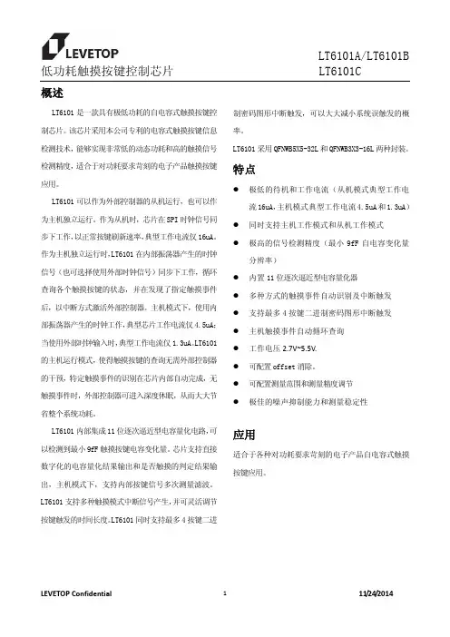
低功耗触摸按键控制芯片 LT6101C 概述LT6101是一款具有极低功耗的自电容式触摸按键控制芯片。
该芯片采用本公司专利的电容式触摸按键信息检测技术,能够实现非常低的动态功耗和高的触摸信号检测精度,适合于对功耗要求苛刻的电子产品触摸按键应用。
LT6101可以作为外部控制器的从机运行,也可以作为主机独立运行。
作为从机时,芯片在SPI时钟信号同步下工作,以正常按键刷新速率,典型工作电流仅16uA。
作为主机独立运行时,LT6101在内部振荡器产生的时钟信号(也可选择使用外部时钟信号)同步下工作,循环查询各个触摸按键的状态,并在发现了指定触摸事件后,以中断方式激活外部控制器。
主机模式下,使用内部振荡器产生的时钟工作,典型芯片工作电流仅4.5uA;当使用外部时钟输入时,典型工作电流仅1.3uA。
LT6101的主机运行模式,使得触摸按键的查询无需外部控制器的干预,特定触摸事件的识别在芯片内部自动完成,无触摸事件时,外部控制器可进入深度休眠,从而大大节省整个系统功耗。
LT6101内部集成11位逐次逼近型电容量化电路,可以检测到最小9fF触摸按键电容变化量。
芯片支持直接数字化的电容量化结果输出和是否触摸的判定结果输出,主机模式下,支持内部按键信号多次测量滤波。
LT6101支持多种触摸模式中断信号产生,并可灵活调节按键触发的时间长度。
LT6101同时支持最多4按键二进制密码图形中断触发,可以大大减小系统误触发的概率。
LT6101采用QFNWB5X5-32L和QFNWB3X3-16L两种封装。
特点z极低的待机和工作电流(从机模式典型工作电流16uA,主机模式典型工作电流4.5uA和1.3uA)z同时支持主机工作模式和从机工作模式z极高的信号检测精度(最小9fF自电容变化量分辨率)z内置11位逐次逼近型电容量化器z多种方式的触摸事件自动识别及中断触发z支持最多4按键二进制密码图形中断触发z主机触摸事件自动循环查询z工作电压2.7V~5.5V.z可配置offset消除。
CHIPHOMER TECHNOLOGY (SHANGHAI) LIMITEDCPT2610 数据手册单/双通道电容性触摸检测芯片September 2019目录CPT2610 数据手册 (1)目录 (2)图目录 (3)1概述 (4)2引脚 (5)2.1引脚排列 (5)2.2引脚说明 (6)3典型应用 (7)3.1双通道典型应用图 (7)3.2单通道典型应用图 (7)4功能描述 (8)4.1按键状态 (8)4.1.1按键输出有效电平选择 (8)4.1.2CPT2610SP8、CPT2610DN8 按键状态获取 (8)4.1.3CPT2610ST6、CPT2610DN6 按键状态获取 (8)4.2按键扫描模式 (8)4.3长时按键触发解除功能 (8)5电气特性 (9)6封装 (10)6.1SOP8L (10)6.2DFN2X2-8L (11)6.3SOT23-6L (12)6.4DFN1.6X1.6-6L (13)7订货信息 (14)8版本信息 (15)图目录图1CPT2610 SOP8L 引脚排列图 (5)图2CPT2610 SOT23-6L引脚排列图 (5)图3CPT2610 DFN1.6X1.6-6L引脚排列图 (5)图4CPT2610 DFN2X2-8L引脚排列图 (5)图5双通道触摸典型应用图 (7)图6单通道触摸典型应用图 (7)图7SOP8L封装尺寸图 (10)图8DFN2X2-8L封装尺寸图 (11)图9SOT23-6L封装尺寸图 (12)图10DFN1.6X1.6-6L封装尺寸图 (13)1 概述CPT2610是一款低功耗双通道/单通道电容检测芯片,具有高效的RF噪音抑制功能,能够准确识别手指触摸引起的微小电容变化,适用于用触摸按键替代机械按键等应用场合;具有实时的自校准和基线跟踪算法,能有效避免因环境因素变化而引起按键误触等情况;支持输出有效电平选择,以满足不同系统平台及应用的要求。
三通道电容式触摸键控制芯片XC2863目录1概述 (3)1.1 特性 (3)1.2 系统框图 (4)2管脚定义 (5)3功能描述 (6)4电气特性 (7)5关键特性 (8)5.1 环境自适应能力 (8)5.1.1环境漂移跟随 (8)5.1.2环境突变校准 (8)6应用指南 (9)7PCB设计 (10)7.1 触摸键设计 (10)7.1.1触摸键 (10)7.1.2触摸键的常用结构 (10)7.1.3触摸键设计 (11)7.2 PCB布线 (11)8封装 (12)1概述XC2863是一款支持宽工作电压范围的三输入三输出电容式触摸键控制芯片。
XC2863内部集成高分辨率触摸检测模块和专用信号处理电路,以保证芯片对环境变化具有灵敏的自动识别和跟踪功能,且内置特殊算法以实现防水、抗干扰等需求。
该芯片可满足用户在复杂应用中对稳定性、灵敏度、功耗、响应速度、防水、带水操作、抗震动、抗电磁干扰等方面的高体验要求。
XC2863为方便用户在应用中可对触摸键的灵敏度进行自主控制,特设置了灵敏度控制位。
用户只需在PCB设计中对这个管脚的逻辑电平值进行设置,就能自由选择在具体应用中芯片体现出的检测灵敏度。
XC2863还内置了上电复位及电源保护电路,在典型应用中可无需任何外部器件,也无需软件、程序或参数烧录。
芯片应用的开发过程非常简单,最大限度的降低了方案成本。
XC2863可广泛适用于遥控器、灯具调光、各类开关以及小家电和家用电器控制界面等应用中。
1.1特性工作电压:2.5V~5.5V三个高灵敏度的触摸检测通道无需进行参数烧录响应速度快抗电磁干扰能力强防水及带水操作功能独特的环境跟踪和自适应能力低功耗(典型工作电流< 25uA)内置上电复位(POR)和电源保护电路CMOS电平输出1.2系统框图XC2863包含PMU和Touch Key Core两个部分,其系统框图如图1所示。
图1 XC2863的系统框图2管脚定义XC2863采用SOP8封装,管脚分布如图2所示。

ESP32-C6系列芯片技术规格书搭载RISC-V32位单核处理器的极低功耗SoC2.4GHz Wi-Fi6(802.11ax)、Bluetooth®5(LE)、Zigbee及Thread(802.15.4)芯片封装内可叠封4MB flash30或22个GPIO,丰富的外设QFN40(5×5mm)或QFN32(5×5mm)封装包括:ESP32-C6ESP32-C6FH4版本1.0乐鑫信息科技版权©2023产品概述ESP32-C6是一款支持2.4GHz Wi-Fi 6、Bluetooth 5、Zigbee 3.0及Thread 1.3系统级芯片(SoC),集成了一个高性能RISC-V 32位处理器和一个低功耗RISC-V 32位处理器、Wi-Fi 、Bluetooth LE 、802.15.4基带和MAC 、RF 模块及外设等。
Wi-Fi 、蓝牙及802.15.4共存,共用同一个天线。
芯片的功能框图如下图所示。
Modules having power in specific power modes:ActiveActive and Modem-sleep Active, Modem-sleep, Light-sleep;optional in Light-sleepAll modesESP32-C6功能框图更多关于功耗的信息,请参考章节3.9低功耗管理。
产品特性Wi-Fi•工作在2.4GHz频段,1T1R•工作信道中心频率范围:2412~2484MHz•支持IEEE802.11ax协议:–仅20MHz非接入点工作模式(20MHz-onlynon-AP mode)–MCS0~MCS9–上行、下行正交频分多址接入(OFDMA),特别适用于高密度应用下的多用户并发传输–下行多用户多输入多输出(MU-MIMO),提升网络容量–波束成形接收端(Beamformee),提升信号质量–信道质量指示(Channel quality indication,CQI)–双载波调制(dual carrier modulation,DCM),提高链路稳定性–空间复用(Spatial reuse),提升网络容量–目标唤醒时间(TWT),提供更好的节能机制•完全兼容IEEE802.11b/g/n协议:–支持20MHz和40MHz频宽–数据速率高达150Mbps–无线多媒体(WMM)–帧聚合(TX/RX A-MPDU,TX/RX A-MSDU)–立即块确认(Immediate Block ACK)–分片和重组(Fragmentation and defragmen-tation)–传输机会(Transmission opportunity,TXOP)–Beacon自动监测(硬件TSF)–4×虚拟Wi-Fi接口–同时支持基础结构型网络(InfrastructureBSS)Station模式、SoftAP模式、Station+SoftAP模式和混杂模式请注意ESP32-C6在Station模式下扫描时,SoftAP信道会同时改变–天线分集–802.11mc FTM蓝牙•低功耗蓝牙(Bluetooth LE):通过Bluetooth5.3认证•Bluetooth mesh•高功率模式(20dBm)•速率支持125Kbps、500Kbps、1Mbps、2Mbps •广播扩展(Advertising Extensions)•多广播(Multiple Advertisement Sets)•信道选择(Channel Selection Algorithm#2)•功率控制(LE Power Control)•Wi-Fi与蓝牙共存,共用同一个天线IEEE802.15.4•兼容IEEE802.15.4-2015协议•工作在2.4GHz频段,支持OQPSK PHY•数据速率:250Kbps•支持Thread1.3•支持Zigbee3.0CPU和存储•高性能RISC-V处理器:–时钟频率:最高160MHz–四级流水线架构–CoreMark®得分:441.32CoreMark;2.76CoreMark/MHz(160MHz)•低功耗RISC-V处理器:–时钟频率:最高20MHz–二级流水线架构•L1cache:32KB•ROM:320KB•HP SRAM:512KB•LP SRAM:16KB•支持的SPI协议:SPI、Dual SPI、Quad SPI、QPI 接口在芯片封装外连接多个flash和其他SPI设备•通过cache加速flash访问•支持flash在线编程(ICP)高级外设接口•30×GPIO口(QFN40)或22×GPIO口(QFN32)•模拟接口:–1×12位SAR ADC,多达7个通道–1×温度传感器•数字接口:–2×UART–1×低功耗UART(LP UART)–2×SPI接口用于连接flash–1×通用SPI接口–1×I2C–1×低功耗I2C(LP I2C)–1×I2S–1×脉冲计数控制器–1×USB串口/JTAG控制器–2×TWAI®控制器,兼容ISO11898-1(CAN 规范2.0)–1×SDIO2.0从机控制器–LED PWM控制器,多达6个通道–1×电机控制脉宽调制器(MCPWM)–1×红外遥控器(TX/RX)–1×并行IO接口(PARLIO)–通用DMA控制器(简称GDMA),3个接收通道和3个发送通道–事件任务矩阵(ETM)•定时器:–1×52位系统定时器–2×54位通用定时器–3×数字看门狗定时器–1×模拟看门狗定时器功耗管理•通过选择时钟频率、占空比、Wi-Fi工作模式和单独控制内部器件的电源,实现精准电源控制•针对典型场景设计的四种功耗模式:Active、Modem-sleep、Light-sleep、Deep-sleep•Deep-sleep模式下功耗低至7µA•Deep-sleep模式下低功耗存储器(LP memory)仍保持工作安全机制•安全启动-内部和外部存储器的权限控制•Flash加密-加密和解密存储器•4096位OTP,用户可用的高达1792位•可信执行环境控制器(TEE)和访问(地址)权限管理(APM)•加密硬件加速器:–AES-128/256(FIPS PUB197)–ECC–HMAC–RSA–SHA–数字签名–Hash(FIPS PUB180-4)•片外存储器加密与解密(XTS_AES)•随机数生成器(RNG)RF模块•天线开关、射频巴伦(balun)、功率放大器、低噪声放大器•802.11b传输功率高达+21dBm•802.11ax传输功率高达+19.5dBm•低功耗蓝牙接收器灵敏度(125Kbps)高达-106dBm应用低功耗芯片ESP32-C6专为物联网(IoT)设备而设计,应用领域包括:•智能家居•工业自动化•医疗保健•消费电子产品•智慧农业•POS机•服务机器人•音频设备•通用低功耗IoT传感器集线器•通用低功耗IoT数据记录器目录产品概述2产品特性3应用51ESP32-C6系列型号对比12 1.1命名规则12 1.2型号对比122管脚13 2.1管脚布局13 2.2管脚概述15 2.3IO管脚182.3.1IO MUX和GPIO管脚功能182.3.2LP IO MUX功能212.3.3模拟功能212.3.4GPIO和LP GPIO的限制23 2.4模拟管脚24 2.5电源252.5.1电源管脚252.5.2电源管理252.5.3芯片上电和复位26 2.6Strapping管脚272.6.1SDIO输入采样沿和输出驱动沿控制282.6.2芯片启动模式控制282.6.3ROM日志打印控制282.6.4JTAG信号源控制29 2.7芯片与flash的管脚对应关系303功能描述31 3.1CPU和存储313.1.1HP CPU313.1.2LP CPU313.1.3片上存储313.1.4封装外flash323.1.5存储器映射323.1.6Cache333.1.7TEE控制器333.1.8访问权限管理(APM)333.1.9超时保护33 3.2系统时钟333.2.1CPU时钟333.2.2低功耗时钟343.3模拟外设343.3.1模/数转换器(ADC)343.3.2温度传感器34 3.4数字外设343.4.1通用异步收发器(UART)343.4.2串行外设接口(SPI)353.4.3I2C接口353.4.4I2S接口353.4.5脉冲计数控制器(PCNT)363.4.6USB串口/JTAG控制器363.4.7TWAI®控制器363.4.8SDIO2.0从机控制器373.4.9LED PWM控制器373.4.10电机控制脉宽调制器(MCPWM)373.4.11红外遥控器(RMT)383.4.12并行IO(PARLIO)控制器383.4.13通用DMA控制器(GDMA)383.4.14事件任务矩阵(ETM)38 3.5射频383.5.1 2.4GHz接收器393.5.2 2.4GHz发射器393.5.3时钟生成器39 3.6Wi-Fi393.6.1Wi-Fi射频和基带393.6.2Wi-Fi MAC403.6.3联网特性41 3.7低功耗蓝牙413.7.1低功耗蓝牙PHY413.7.2低功耗蓝牙链路控制器41 3.8802.15.4423.8.1802.15.4PHY423.8.2802.15.4MAC42 3.9低功耗管理42 3.10定时器433.10.1系统定时器433.10.2通用定时器433.10.3看门狗定时器43 3.11加密/安全组件443.11.1AES加速器(AES)443.11.2ECC加速器(ECC)453.11.3HMAC加速器(HMAC)453.11.4RSA加速器(RSA)453.11.5SHA加速器(SHA)453.11.6数字签名(DS)463.11.7片外存储器加密与解密(XTS_AES)463.11.8随机数发生器(RNG)463.12外设管脚分配474电气特性50 4.1绝对最大额定值50 4.2建议电源条件50 4.3VDD_SPI输出特性50 4.4直流电气特性(3.3V,25°C)51 4.5ADC特性51 4.6功耗特性524.6.1Active模式下的RF功耗524.6.2其他功耗模式下的功耗53 4.7可靠性535射频特性55 5.1Wi-Fi射频555.1.1Wi-Fi射频发射器(TX)特性555.1.2Wi-Fi射频接收器(RX)特性56 5.2低功耗蓝牙射频585.2.1低功耗蓝牙射频发射器(TX)特性585.2.2低功耗蓝牙射频接收器(RX)特性59 5.3802.15.4射频615.3.1802.15.4射频发射器(TX)特性625.3.2802.15.4射频接收器(RX)特性626封装637相关文档和资源64附录A–ESP32-C6管脚总览65修订历史67表格1-1ESP32-C6系列芯片对比12 2-1QFN40封装管脚概述16 2-2QFN32封装管脚概述17 2-3QFN40封装IO MUX管脚功能19 2-4QFN32封装IO MUX管脚功能19 2-5LP IO MUX功能21 2-6模拟功能22 2-7模拟管脚24 2-8电源管脚25 2-9电压稳压器25 2-10上电和复位时序参数说明26 2-11Strapping管脚默认配置27 2-12Strapping管脚的时序参数说明27 2-13SDIO输入采样沿/输出驱动沿控制28 2-14芯片启动模式控制28 2-15ROM日志打印控制29 2-16JTAG信号源控制29 2-17QFN40封装芯片与封装外flash/PSRAM的管脚对应关系30 3-1外设和传感器管脚分配47 4-1绝对最大额定值50 4-2建议电源条件50 4-3VDD_SPI内部和输出特性50 4-4直流电气特性(3.3V,25°C)51 4-5ADC特性51 4-6ADC校准结果52 4-7Active模式下Wi-Fi(2.4GHz)功耗特性52 4-8Active模式下低功耗蓝牙功耗特性52 4-9Active模式下802.15.4功耗特性53 4-10Modem-sleep模式下的功耗53 4-11低功耗模式下的功耗53 4-12可靠性认证53 5-1Wi-Fi射频规格55 5-2频谱模板和EVM符合802.11标准时的发射功率55 5-3发射EVM测试55 5-4接收灵敏度56 5-5最大接收电平57 5-6接收邻道抑制57 5-7低功耗蓝牙射频规格58 5-8低功耗蓝牙-发射器特性-1Mbps58 5-9低功耗蓝牙-发射器特性-2Mbps58 5-10低功耗蓝牙-发射器特性-125Kbps59 5-11低功耗蓝牙-发射器特性-500Kbps59 5-12低功耗蓝牙-接收器特性-1Mbps595-13低功耗蓝牙-接收器特性-2Mbps60 5-14低功耗蓝牙-接收器特性-125Kbps61 5-15低功耗蓝牙-接收器特性-500Kbps61 5-16802.15.4射频规格61 5-17802.15.4发射器特性-250Kbps62 5-18802.15.4接收器特性-250Kbps62 7-1QFN40封装管脚总览65 7-2QFN32封装管脚总览66插图插图1-1ESP32-C6系列芯片命名规则12 2-1ESP32-C6管脚布局(QFN40封装,俯视图)13 2-2ESP32-C6管脚布局(QFN32封装,俯视图)14 2-3ESP32-C6电源管理26 2-4上电和复位时序参数图26 2-5Strapping管脚的时序参数图28 3-1地址映射结构32 6-1QFN40(5×5mm)封装63 6-2QFN32(5×5mm)封装631ESP32-C6系列型号对比1ESP32-C6系列型号对比1.1命名规则F H/N xflash ⼤⼩ (MB)flash 温度H:⾼温N:正常封装内 flash芯⽚系列图1-1.ESP32-C6系列芯片命名规则1.2型号对比表1-1.ESP32-C6系列芯片对比1更多关于芯片丝印和包装的信息,请参考小节6封装。

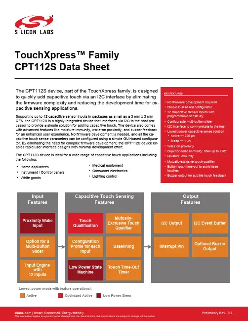
TouchXpress™ Family CPT112S Data SheetThe CPT112S device, part of the TouchXpress family, is designed to quickly add capacitive touch via an I2C interface by eliminating the firmware complexity and reducing the development time for ca-pacitive sensing applications.Supporting up to 12 capacitive sensor inputs in packages as small as a 3 mm x 3 mm QFN, the CPT112S is a highly-integrated device that interfaces via I2C to the host pro-cessor to provide a simple solution for adding capacitive touch. The device also comes with advanced features like moisture immunity, wake-on proximity, and buzzer feedback for an enhanced user experience. No firmware development is needed, and all the ca-pacitive touch sense parameters can be configured using a simple GUI-based configura-tor. By eliminating the need for complex firmware development, the CPT112S device en-ables rapid user interface designs with minimal development effort.The CPT112S device is ideal for a wide range of capacitive touch applications including the following:•Home appliances•Instrument / Control panels •White goods•Medical equipment •Consumer electronics •Lighting controlOptimized ActiveLowest power mode with feature operational:ActiveLow Power SleepFeature List and Ordering Information 1. Feature List and Ordering InformationFigure 1.1. CPT112S Part NumberingThe CPT112S has the following features:•Capacitive sensing input engine with 12 inputs•Post-sample touch qualification engine•Configuration profile space in non-volatile memory•I2C event buffer with interrupt pin to signal when new touch events have been qualified•Low power state machine to minimize current draw in all use cases•Capacitive proximity sensing input•Buzzer output•Mutually-exclusive touch qualifier•Touch time-out timerTable 1.1. Product Selection Guide2. Typical Connection Diagrams2.1 Signal, Analog, and Power connectionsFigure 2.1 Connection Diagram on page 2 shows a typical connection diagram for the power pins of CPT112S devices.Figure 2.1. Connection Diagram2.2 ConfigurationThe diagram below shows a typical connection diagram for the configuration connections pins. The ToolStick Base Adapter is available on the evaluation board.Figure 2.2. Configuration Connection Diagram3. Electrical Specifications3.1 Electrical CharacteristicsAll electrical parameters in all tables are specified under the conditions listed in Table 3.1 Recommended Operating Conditions on page 4, unless stated otherwise.3.1.1 Recommended Operating ConditionsTable 3.1. Recommended Operating Conditions3.1.2 Power ConsumptionSee 3.4 Typical Performance Curves for power consumption plots.Table 3.2. Power Consumption3.1.3 Reset and Supply MonitorTable 3.3. Reset and Supply Monitor3.1.4 Configuration MemoryTable 3.4. Configuration Memory3.1.5 Capacitive SenseTable 3.5. Capacitive Sense3.1.6 Buzzer OutputTable 3.6. Buzzer Output3.2 Thermal ConditionsTable 3.7. Thermal Conditions3.3 Absolute Maximum RatingsStresses above those listed in Table 3.8 Absolute Maximum Ratings on page 9 may cause permanent damage to the device. This is a stress rating only and functional operation of the devices at those or any other conditions above those indicated in the operation list-ings of this specification is not implied. Exposure to maximum rating conditions for extended periods may affect device reliability. For more information on the available quality and reliability data, see the Quality and Reliability Monitor Report at / support/quality/pages/default.aspx.Table 3.8. Absolute Maximum Ratings3.4 Typical Performance CurvesFigure 3.1. Active Mode Processing Time Per SensorNote: Active mode processing time per sensor measured with sensors configured to 1x accumulation, 8x gain. Sensor sampling and system processing time is included with mutually-exclusive buttons, the buzzer, slider, and touch time-outs disabled.Figure 3.2. Current vs. Active Mode Scan Period — Base Current ConsumptionFigure 3.3. Current vs. Active Mode Scan Period — Current Consumption for Each Additional SensorNote: Active mode scan period current draw measured with free run mode disabled and all 12 sensors enabled at 4x accumulation, 8x gain. In addition, the buzzer, slider, and mutually-exclusive button groups were disabled.Figure 3.4. Typical V OH CurvesFigure 3.5. Typical V OL Curves4. Functional Description4.1 Capacitive Sensing Input 4.1.1 IntroductionThe capacitive to digital converter uses an iterative, charge-timing self-capacitance technique to measure capacitance on an input pin.Sampling is configured and controlled by settings in the non-volatile configuration profile, which can be changed through the 2-pin con-figuration interface.C a p a c i t a n c eTimeFigure 4.1. Capacitive Sense Data Types4.1.2 Touch Qualification CriteriaThe device detects a touch event when an inactive (untouched) input enabled by the input enable mask detects an sequence of meas-urements that cross the active threshold.The device detects a touch release event when an active (touched) input enabled by the input enable mask detects an sequence of measurements that cross the inactive threshold.The debounce configuration profile parameter defines how many measurements in a row must cross a threshold before a touch or re-lease is qualified. In electrically noisy environments more heavily filtered data is used for qualification.4.1.3 ThresholdsCapacitive sensing inputs use input-specific thresholds for touch qualification. Each input uses two thresholds, one to detect inactive-to-active transitions on the input, and another to determine active-to-inactive transitions on the input. The inputs use two thresholds to add hysteresis and prevent active/inactive ringing on inputs. Each threshold can be set through Simplicity Studio tools and all thresholds are stored in non-volatile memory in the device's configuration profile.Thresholds are defined as percentages of a capacitive sensing input's touch delta.4.1.4 Debounce CounterEach capacitive sensing input maintains its own debounce counter. For an inactive sensor, this counter tracks the number of succes-sive samples which have crossed that input's active threshold. For an active sensor, this counter tracks the number of successive sam-ples which have crossed the inactive threshold. When the counter reaches a terminal value defined in the the configuration profile, the touch/release event is qualified.4.1.5 Touch DeltasEach capacitive sensing input uses a stored touch delta value that describes the expected difference between inactive and active ca-pacitive sensing output codes. This value is stored in the configuration profile for the system and is used by the touch qualification en-gine, which defines inactive and active thresholds relative to the touch delta.The touch deltas are stored in the configuration profile in a touch delta/16 format. For this reason, touch deltas must be configured as multiples of 16.4.1.6 Auto-Accumulation and AveragingCapacitive sensing inputs have an auto-accumulate and average post-sample filter that can be used to improve signal strength if nee-ded. Settings stored in the configuration profile can configure the engine to accumulate 1, 4, 8, 16, 32, or 64 samples. After the defined number of samples have been accumulated, the result is divided by either 1, 4, 8, 16, 32, or 64, depending on the accumulation setting. This auto-accumulated and averaged value is the sample output used for all touch qualification processing. Note that sample time per sensor increases as the level of accumulation increases. To reduce current consumption, the engine should not be set to auto-accumu-late unless it is required to achieve acceptable signal strength due to thick overlays or other system-level factors.4.1.7 Drive strengthThe drive strength of the current source used to charge the electrode being measured by the capacitive sensing input can be adjusted in integer increments from 1x to 8x (8x is the default). High drive strength gives the best sensitivity and resolution for small capacitors, such as those typically implemented as touch-sensitive PCB features. To measure larger capacitance values, the drive strength should be lowered accordingly. The highest drive strength setting that yields capacitive sensing output which does not saturate the sensing engine when the electrode is active (touched) should always be used to maximize input sensitivity.4.1.8 Active Mode Scan EnableActive mode scanning of capacitive sensing inputs is controlled by an enable setting for each capacitive sensing input. This setting is stored in the configuration profile.4.1.9 Active Mode Scan PeriodThe capacitive sensing input engine stays in active mode whenever one or more inputs have qualified as active. During this time, the sensors scan at a periodicity defined by the active mode scan period, which is stored in the configuration profile. Every active mode scan pushes new samples through the processing engine, which checks for new touch and release events on all enabled inputs.If free run mode is enabled, the engine will repeatedly scan all enabled inputs during the active mode scan period. In this mode of operation, the active mode scan period is used as a timer to determine how much time has passed since the last qualified active sensor has been seen. When a defined amount of time without a qualified touch event has occurred, the engine switches to a low power mode using the sleep mode scan period, and conserves current.If free run mode is disabled, the engine will enter a low power state after completing one scan of all enabled inputs and processing the resulting samples. The engine will remain in this low power state until it wakes, at a time defined by active mode scan period, to perform another scan.4.1.10 Active Mode Scan TypeThe active mode scan type, which is stored in the configuration profile, controls whether the capacitive sensing engine in active mode will scan only once during the active mode scan period before going to sleep, or whether the engine will continue scanning as quickly as possible during the active mode scan period, never entering a low power state.For optimal responsiveness, the engine should be configured to run with free run mode enabled. Setting the scan mode to 'free run' causes touch qualification on a new touch to occur as quickly as the scanning engine can convert and process samples on all sensors. In this mode, qualification time is not bounded by active mode scan period, and is only bounded by scanning configuration factors such as the debounce setting, the number of enabled sensors, the accumulation setting on each sensor, and the timing constraints of any enabled component.For optimal current draw when in active mode, the engine should be configured to use the 'one scan per period' mode setting. In this case, touch qualification is bound by the scan period and the debounce setting of the device.Touch Event(t = 0 ms)10 ms20 ms30 ms40 msFigure 4.2. Timing and Current — One Sample Per Period ModeTouch Event10 ms20 ms30 ms40 ms(t = 0 ms)4.1.11 Sleep Mode Scan PeriodThe sleep mode scan period defines the rate at which a scan of the inputs enabled as wake-up sources are sampled. Each enabled sensor can also be enabled as a wake-up source. After the sleep mode scan completes, the scan is processed for a qualified candidate touch. If a candidate touch is qualified, the system wakes form sleep mode and enters active mode scanning.The sleep mode scan period is stored in the configuration profile and is defined in units of ms.4.1.12 Active Mode and Sleep Mode TransitionsCapacitive sensing inputs will stay in active mode until no inputs detect qualified touches for a span of time defined by the counts until sleep parameter stored in the configuration profile. The scan period of enabled inputs is defined by the active mode scan period, also found in the configuration profile. If free run mode is enabled, the active mode sensing engine will remain awake and scanning the sen-sors as fast as possible. If free run mode is disabled, the engine will put itself into a low power state for the remainder of the active mode scan period, after a scan has completed.When in sleep mode, the sensing engine will wake at a period defined by sleep mode scan period to do a scan on sensors that have been enabled as wakeup sources. If the engine finds a candidate touch in this state, the system reverts to active mode to continue scanning.Note that in systems where a proximity input is selected, the sleep mode scan engine uses conversions on the proximity input instead of sensors enabled as wakeup sources.Devices configured to wake on a touch will attempt to qualify the candidate touch that initiated the sleep-to-active transition. If qualifica-tion completes successfully, the device will signal this qualification to the external system. Touch qualification of this candidate touch uses the same active mode thresholds, debounce setting, and active mode scan period settings as any touch that occurs during active mode scanning.D e v i c eE x e c u t i o nFigure 4.4. Active and Sleep Transitions4.2 I2C Event Buffer Interface4.2.1 IntroductionThe event buffer I2C interface provides an event-driven, packetized communication system describing newly qualified events generated by the capacitive sensing input engine.The interface provides access to a first-in-first-out buffer of data packets. When the sensing engine generates these packets and push-es them onto the buffer. The interface then signals a host to indicate that one or more packets are available in the buffer by activating the event buffer interrupt pin.The interrupt pin is defined as active-low and operates as a push-pull digital output.The host reads the packets through an I2C interface, with the host acting as an I2C master. Once all packets have been fully transmit-ted across the I2C interface, the event buffer interrupt pin is de-activated. The device will remain in active mode until no packets remain in the buffer, even if no sensors have been qualified as active for the period of time defined by the active mode scan period and the counts before sleep value.4.2.2 Packet retrieval in operational modeWhen the least significant byte of the CRC of an event packet has been transferred during a master read transaction, that event is popped from the device's buffer. If only a part of the event is read, the event will stay in the buffer and will be transmitted again by the device during the next read.If the host initiates a master read when the device is in operational mode but the interrupt pin is not active, signifying that the device has no events in its buffer to transmit, the device will NACK its slave address on the bus.If the I2C master sends a stop condition on the bus before the entire three-byte packet has been read, the device will not pop the pack-et from its internal buffer. Instead, the I2C state machine will reset, and the next transaction will begin with the first byte of the same event that was being read in the previous, prematurely-terminated transaction.The I2C event buffer has a depth of 22 events. If the host does not read events promptly after seeing the interrupt pin go active, there is the possibility of a buffer overflow. In the event of an overflow, the I2C engine will discard the oldest events first.New I2C packets will only be generated at the active mode sample rate, and so the buffer will only fill at a maximum of 12 packets (in the case of 12 simultaneous touch/releases) per sample period. If the host runs the I2C bus at 400kHz and reads packets as soon as the interrupt pin activates, all packets can be read from the buffer in 1 to 2 ms, which is faster than the rate at which a new active mode scan sequence can complete.4.2.3 Event Packet StructureEvery qualified event detected by the capacitive sensing input engine generates a single packet that can be retrieved by the host pro-cessor through the event buffer I2C interface. The packet is an atomic data unit that fully describes the generated event.Note: The bytes in the packet are transmitted MSB first.Each packet has a standard structure that can be parsed by the host.Table 4.1. Standard Packet StructureThe packet counter is a 4-bit number stored in the upper bits of byte 1. Each new event will be assigned a counter value that is +1 from the last qualified event. After event 15, the counter wraps back to 0 for the next event. The counter captures the temporal nature of touch events so that a host can reconstruct a sequence of events over time. Also, the host can use the counter value to determine if a packet has been lost due to a buffer overflow.The event type is a 4-bit value describes the originator of the event. For instance, the source could be a capacitive sensing button. The event type is stored in the lower 4 bits of byte 1.The event description bytes define characteristics of the event that have been qualified. Event descriptions are defined relative to the event source. An event source that is a capacitive sensing input will have a defined set of valid event description values. Those same values will mean something different for a different type of event source, such as a slider. Event description values are defined relative to the event type field of byte 1.Touch Event I2C Slave Address+ read bitCSxx index reserved byte 0byte 1byte 2byte 3Touch Release Event I2C Slave Address+ read bitCSxx index reserved byte 0byte 1byte 2byte 3Slider Event I2C Slave Address+ read bitslider position(MSB)slider position(LSB) byte 0byte 1byte 2byte 3packetcounter0010eventtype0000packetcounter0011eventtype0001packetcounter0100eventtype0010Figure 4.5. I2C Event Buffer Packet Structure4.2.4 Defined Event TypesThe device assigns the following event types to events.Table 4.2. Event Type MappingNote that this event type value is stored in the lower 4 bits of the first byte of a packet. The upper 4 bits are a packet counter value.4.2.5 Description Bytes for Touch EventsA touch or release event uses only one byte of the description field. That field identifies which sensor caused the touch or release event as shown below.Table 4.3. Touch or Release Event Sensor Mapping4.2.6 Description Bytes for Slider EventsThe slider activity description field uses two bytes to describe the position of the slider, which can be any value between 0 (0x0000) and 65534 (0xFFFE). The most-significant byte of this value is transmitted in the first byte (byte 2 of the event packet), and the least-signifi-cant byte is transmitted second (byte 3 of the event packet).When the slider is released, a final slider event will be transmitted with 0xFFFF in the two-byte field.4.2.7 Event Buffer I2C Slave AddressThe device's I2C slave address is configurable through the configuration profile. The device will ACK its slave address only when the interrupt pin is low, signalling that a packet is ready to be read by the host. If the interrupt pin is logic high, the device will not ACK its slave address.4.3 Capacitive Proximity Sensing4.3.1 Wake on ProximityThe wake on capacitive proximity detection engine monitors for the presence of a conductive object such as a hand to move within detectable range of the sensor. When the engine detects an object, the device wakes from sleep and can begin qualifying touch events on all sensors enabled for active mode sensing.4.3.2 Proximity ConfigurationThe proximity sensing feature uses a single sensor input for proximity qualification. The configuration profile stores the pin chosen by the user. The sensor used for proximity qualification should also have a drive strength setting that is as high as possible without saturat-ing the input when no conductive object is in proximity to the proximity sensor. The accumulation setting of the input is also configura-ble.The proximity threshold controls the sensitivity of the input. A lower threshold setting increases sensitivity and increases the range of the sensor.A proximity sensing input cannot be used for touch qualification, and so the active and inactive thresholds are not used for proximity sensors. Additionally, the proximity input has no effect on other components of the device such as mutually exclusive button groups, buzzer output, touch time out timers, and sliders.4.4 SliderThe device supports creation of a single slider that is composed of two or more capacitive sensing input pins. The pins chosen as slider inputs are assigned to the slider feature through the configuration profile.The configuration profile also stores a value designated as the highest positional value that can be derived by the slider engine. That highest value is used to derive the values of all intermediate positions on the slider array.When a capacitive sensing input pin is designated as a slider input, it will no longer function as a 'button' input and will not generate button style touch/release events across the I2C buffer interface.Touching the slider pads and moving a finger along a slider pad generates an event packet of type Slider, with the remaining two bytes of the packet describing the calculated active position of the slider.The range of possible reported slider active positions can be 0 to the maximum value of the slider as defined in the configuration profile,which can be any value between 40 and 65534. The 65535 (0xFFFF) value is reserved for a slider untouched event.Position 0 is always assigned to the lowest CSxx sensor enabled as a slider input. The maximum position value of the slider is assigned to the highest CSxx sensor enabled as a slider input. All slider inputs in between are assumed to be routed to the slider contiguously,lowest to highest.InvalidConfigurationValidConfigurationincreasing slider positionValidConfigurationpositionFigure 4.6. Slider Behavior and Layout ConstraintsSlider touch qualification uses the same touch deltas and thresholds that are defined in the configuration profile for all enabled sensors.The user should configure slider sensors through the configuration profile, just as one would configure a sensor assigned to a capaci-tive button.For optimal performance, each sensor used in the slider should have roughly the same touch surface area dimensions.If the touch-timeout feature is enabled, slider-assigned inputs will also be subject to being qualified as releases by the touch-timeout feature.The mutually exclusive button grouping feature does not affect slider-assigned sensors. Even if the mutually exclusive button grouping feature is enabled, multiple slider-assigned sensors can still be used to resolve a finger's position on the slider.4.5 Touch Time-OutThe touch time-out feature can be enabled and disabled through the configuration profile. When enabled, the device will monitor touch event duration on each input independently.When a touch event exceeds a duration specified in the configuration profile, the device forces a release event, even if the user is still actively touching the sensor.The feature qualifies a touch release by adding the configured touch delta value for that sensor to the sensor's current baseline value. By doing this, the raw data-to-baseline delta created by the touch will be removed, and the touch qualification engine will see this as a touch release event.When the user removes a finger from a sensor that had been qualified active but has been qualified released through touch timeout, the resulting raw-to-baseline negative delta will be aggressively tracked downward by the baseline, resulting in a sensor that remains sensi-tive to successive touches.The touch timeout duration is configured globally, so all inputs are monitored for the same touch duration.If both the touch timeout feature and the mutually exclusive button group feature are enabled, the timeout timer will only run on the touch that is externally reported as being active.4.6 Buzzer Output4.6.1 IntroductionThe buzzer output engine produces a square wave of a configurable duration and frequency when a capacitive sensing input goes from inactive to active. The feature can be enabled and disabled through the configuration profile. The configuration profile also includes the settings for active duration and frequency.Device ExecutionActiveOptimizedActiveSleepNo Touch, Buzzer InactiveFigure 4.7. Effects of the Buzzer on Current Draw — Active Mode, No Touch, Buzzer InactiveDevice ExecutionActiveOptimizedActiveSleepTouch Detected, Buzzer ActiveFigure 4.8. Effects of the Buzzer on Current Draw — Active Mode, Touch Detected, Buzzer Active4.6.2 Buzzer ConfigurationWhen enabled, buzzer output will appear on the CS11/buzzer pin (pin 10) of the device. When buzzer output is enabled, CS11 is not available for capactive input sensing.When activated, the buzzer will remain active for either the duration specified in the configuration profile, or until the last active sensor has qualified a touch release.The configuration profile supports configuration of output frequencies ranging from 1 kHz to 4 kHz.The configuration profile can configure the buzzer output pin to either push pull mode or open drain mode.4.7 Mutually Exclusive ButtonsWhen enabled through the configuration profile, this system allows one and only one capacitive sensing input to be qualified as active at a time. The first sensor active will remain the only sensor active until released. The device will internally qualify multiple touch and release events but will not report them.If multiple sensors have been internally qualified as active, the first sensor's touch event will be reported. If a touch event occurs simul-taneously on more than one sensor, the touch with the highest touch delta will be reported.If two sensors are qualified as active and the sensor being reported as active qualifies a touch release, the device will report that re-lease and then report a touch qualification on the still-active second sensor.In the case where a device has simultaneously qualified more than two active sensors and the reported active sensor qualifies and reports a release, the remaining qualified sensor with the highest sensor name will then be reported. For example, if sensors CS00,CS01, and CS02 are active with CS00 externally reported as active, after CS00's release, CS02 would be externally reported as an active sensor unless the device has already qualified a touch release on CS02.If both the touch timeout feature and the mutually exclusive button group feature are enabled, the timeout timer will only run on the touch that is externally reported as being active.Device Executionphysical touch on pad touch reported by CPT device release reported by CPT deviceFigure 4.9. Mutually-Exclusive Button Operation4.8 Self Testing4.8.1 IntroductionWhen the self-test feature is enabled through the configuration profile, the device performs a check on all enabled capacitive sensing inputs upon startup to determine whether the sensing input pins are erroneously shorted to ground or supply. If a short or open is found on a sensor, the self test feature will signal that an error has been found through a port pin. The feature will then disable that sensor before beginning touch qualification scans on all sensors left enabled.4.8.2 Test Failure SignalingIf the self test check reveals an error, the device will toggle the I2C buffer interrupt pin at a frequency of 2 Hz. This toggling will persist for two seconds if the device detects one or more self test errors.4.9 Configuration ProfileThe configuration interface is used by the device to configure default values and performance characteristics that effect capacitive sensing. The configuration data can be programmed through the Configuration interface (Config Clk and Config Data pins) using [Con-figurator] in Simplicity Studio.Several configuration profile templates are available in Simplicity Studio to provide a starting point for development.。
XC6192SeriesPower saving Push Button Load switch ETR33010-003■BLOCK DIAGRAMXC6192AXC6192B* Diodes inside the circuit are an ESD protection diodes and a parasitic diodes.OUTSSV IN SWSHDNOUTSSV IN SWSHDNXC6192Series ■PRODUCT CLASSIFICATION●Ordering Information(*1)●Selection GuideParts No. Turn-On Delay Time (s) Turn-Off Delay Time (s) PackageXC6192AA05ER-G0.5s 5sUSP-8B06XC6192AA10ER-G 10sXC6192BANNER-G Not applicable■PIN CONFIGURATION*The dissipation pad for the USP-8B06 package should be solder-plated in recommended mount pattern and metal masking so as to enhance mounting strength and heat release.When taking out a potential of the heat-sink, connect with V SS pin (#5 pin).■PIN ASSIGNMENTPIN NUMBER PIN NAMEFUNCTIONUSP-8B061 V IN Power Supply Input2 N.C No connection pin(The N.C pin should be connected the V SS pin.) 3 SW Push Button Signal input pin 4 PG Power Good Status Output 5 V SS Ground Pin6 TEST The TEST pin must be connected the V SS pin.7 SHDNForced Shutdown pin 8V OUTOutput pin■PIN FUNCTIOS ASSIGNMENTPIN NAME SIGNALSTATUS SW (*3)L ActiveH Keep the current state OPEN Undefined State (*1) SHDN (*3)LKeep the current state H Shut down OPEN Undefined State (*1) PGLow impedance V OUT < V RUSH (*2) High impedanceV OUT ≥ V RUSH (*2)(*1) Please do not leave the SW pin and the SHDN pin open. Each should have a certain voltage (*2) Please refer to electrical characteristics.(*3)Please refer to notes on use.43215867V OUT SHDN TEST V SS V IN N.C SW PGUSP-8B06(BOTTOM VIEW)XC6192Series ■ABSOLUTE MAXIMUM RATINGSXC6192Series■TEST CIRCUITSTest Circuit (1)Unless otherwise stated, V SS common, V IN =6.0V, V SW =6.0V, V SHDN =0V, V PG =Open, I OUT =0mA, C IN =0.1μF, C L =0.1μF■TYPICAL APPLICATION CIRCUIT【Typical Examples】(*1) Please select freely according to the threshold of the MCU's I/O.XC6192Series■OPERATIONAL EXPLANATIONThe XC6192 series A type fixes V OUT at “H” voltage (same level as the V IN pin voltage) when “L” voltage is input the required time into the SW pin, and shuts down V OUT (same level as GND) when “L” voltage is subsequently input the required time into the SW pin, thereby realizing alternating ON/OFF control (*1). Two shutdown methods are available: inputting “H” voltage into the SHDN pin, and inputting “L” voltage the required time into the SW pin.(*1)Alternating ON/OFF control on this IC is a system that alternates between VOUT “H” voltage and shutdown each time “L” voltage is input the required time into the SW pin.The B type fixes V OUT at “H” voltage when “L” voltage is input the required time into the SW pin. After V OUT is fixed at “H” voltage, the signal is not accepted if “L” voltage is subsequently input into the SW pin. The shutdown method is inputting “H” voltage into the SHDN pin.As protective functions, the XC6192 series is equipped with a rush current prevention circuit and a short-circuit protection circuit.OUTV IN SWSHDN■OPERATIONAL EXPLANATION (Continued)[Turn-On sequence: Fig.3]On the XC6192 series, when “L” voltage is input for the duration T OND into the SW pin with V OUT fixed at “L” voltage, the Pch pre-driver transistor PM1 (Fig.1) turns ON and V OUT starts to rise. If the SW pin is switched from “L” voltage to “H” voltage while V OUT is rising by PM1, V OUT will change to the shutdown state.When the V OUT pin voltage reaches Inrush Current Limit Voltage (V RUSH: refer to Electrical Characteristics), the main driver transistor PM2 (Fig.1) turns ON, and V OUT is fixed at “H” voltage even if the SW pin voltage changes to “H” voltage.When the V OUT pin voltage reaches V RUSH, the Nch transistor NM1 that is connected to the PG pin (Fig.1) turns OFF and the PG pin changes to high impedance.These operations suppress rush current to the capacitor that is connected to the V OUT pin and allow the input power supply to maintain stability. In addition, by connecting the PG pin to the Enable pin of the device that follows the XC6192 series, malfunctioning of that device is prevented. (Fig.2)[Shutdown sequence: Fig.4]On the XC6192 series, when one pulse of “H” voltage (at least 1ms as a guideline) is input into the SDHN pin with V OUT fixed at “H” voltage, V OUT changes to the shutdown state and the IC enters the standby state.[Turn-Off sequence: Fig.5]On the A type, when “L” voltage is input into the SW pin for the duration T OFFD with V OUT fixed at “H” voltage, V OUT shuts down. After shutdown, returning the SW pin to “H” voltage reduces the supply current to the standby current while holding the IC’s logic.The B type does not have this function.V OUT Pin VoltagePG Pin VoltageSHDN pin Voltage[Operation after Turn-On: Fig. 6]On the A type, when “L” voltage is input into the SW pin for the duration T OND and V OUT is fixed at “H” voltage, and then “L”voltage is input into the SW pin for the duration T OFFD , the Turn-Off sequence cannot be initiated. To initiate the Turn-Off sequence, “H” voltage must be input into the SW pin, and then “L” voltage must again be input for the duration T OFFD . The B type does not have a Turn-Off sequence by SW pin.[Operation after Turn-Off:Fig.7]On the A type, when “L” voltage is input into the SW pin for the duration T OFFD and V OUT is shut down, and then “L” voltage isinput into the SW pin for the duration T OND , the Turn-On sequence cannot be initiated.To initiate the Turn-On sequence, “H” voltage must be input into the SW pin, and then “L” voltage must again be input for the duration T OND .The B type does not have a Turn-Off sequence by SW pin.[Operation after shutdown: Fig. 8]On the XC6192 series, in order to initiate the Turn-On sequence after “H” voltage is input into the SHDN pin and V OUT is shut down, “H” voltage must be input into the SW pin and then “L” voltage must again be input for the duration T OND.[Inrush current limit and output short circuit protection:Fig.9 ]The XC6192 series has a function that limits rush current and a circuit that shuts down the output when an output short-circuit is detected.During the time until the V OUT pin voltage reaches V RUSH during the Turn-On sequence, only PM1 turns ON, and therefore the voltage rises through the Pre-driver On Resistor (R ONP: refer to the Electrical Characteristics).When the V OUT pin voltage reaches V RUSH or more, PM2 turns ON and rush current limiting is released.The rush current at the instant when PM1 turns ON is calculated using the following equation.Inrush Current = V IN / R ONP (A)In addition, during the time until the V OUT pin voltage reaches V RUSH by means of the rush current limiting function, the load current while V OUT rises must be set to less than the value given by the equation below.Start-up Load Current < (V IN – V RUSH (Max.)) / R ONP (A)Example: 4.2V – 4.15V / 135 Ohms = 0.359mA;Note this very low 0.359mA is used to charge the output capacitors. If startup load current exceeds this, the output current will pass thru PM1 only, and have a 135 ohm resistor creating a voltage drop. If it’s noticed that V OUT is significantly below V IN, please ensure start-up load current is NOT exceeded.If the V OUT pin voltage drops below the Short Circuit Detect Voltage (V SHORT: refer to the Electrical Characteristics) after the Turn-On sequence, a short-circuit is detected and PM1 and PM2 are latched in the OFF state, causing V OUT to shut down. The relation between the output current (I SHORT) and V SHORT when a short circuit occurs is given by the equation below.I SHORT = (V IN - V SHORT) / R ON (A)The equation for the maximum output current is as follows.I OUT (Min.) = (V IN - V SHORT (Max.)) / R ON (Max.) (A)[SW pin]When “L” voltage is input into the SW pin for the duration T OND with the IC in the standby state, the pin fixes V OUT at “H” voltage.On the A type, when V OUT is fixed at “H” voltage, “L” voltage can be input for the duration T OFFD to shut down V OUT.[SHDN pin]This pin shuts down V OUT when one pulse of “H” voltage (1ms or more as a guideline) is input into the SHDN pin with V OUT fixed at “H” voltage.[PG pin]NM1 and R2 (Fig.1) are connected to the PG pin.NM1 is an Nch MOSFET and is synchronized with the GATE signal of PM2, so NM1 turns OFF when PM2 turns ON.[VOUT pin]PM1, PM2, and R1 (Fig.1), and R2 (Fig.1) and the CL discharge transistor NM2 (Fig.1) are connected to the output pin.PM1 is a Pch MOSFET, and is effective in preventing rush current.PM2 is a Pch MOSFET and functions as the main driver.NM2 is an Nch MOSFET, and is synchronized with the GATE signal of PM1. Therefore, when PM1 turns ON, NM2 turns OFF.[SW Circuit]This circuit transmits the signal input into the SW pin to the internal circuitry.[SHDN Circuit]This circuit transmits the signal input into the SHDN pin to the internal circuitry.[VREF & POR]This circuit supplies the internal circuit reference voltage and is a reset circuit that is input into the logic circuitry.[Type Select]This circuit selects the product type.[Turn-On Delay Counter]This circuit count-controls the time until V OUT is fixed at “H” voltage after “L” voltage is input into the SW pin.During the time until the count is completed, the counter circuit can be returned to the initial state by inputting “H” voltage into the SW pin.[Turn-Off Delay Counter]This circuit only operates on the A type.When V OUT is fixed at “H” voltage, this circuit count-controls the time from input of “L” voltage into the SW pin until V OUT shuts downDuring the time until the count is completed, the counter circuit can be returned to the initial state by inputting “H” voltage into the SW pin.[VREF2 & POR2]This circuit sets the initial state of the V OUT pin.The circuit is set so that V OUT is in the shutdown state when the power is turned on, so there is no need to input “H” voltage into the SHDN pin after power is supply to shut down the output.[Inrush Current Limit]This circuit limits rush current until the V OUT pin voltage reaches V RUSH.[Short Circuit Protect]This circuit outputs a shutdown signal if the V OUT pin voltage reaches V SHORT.[Gate Slope]After the V OUT pin voltage reaches V RUSH, this circuit gradually changes the GATE voltage of PM2 from “H” voltage to “L” voltage.■NOTES ON USE1) For temporary, transitional voltage drop or voltage rising phenomenon. The IC is liable to malfunction should the ratings beexceeded.2) Please use this IC within the specified operating ranges.3) In some cases, power supply noise may cause malfunctioning of the internal counter circuit. Sufficiently reinforce the V IN,V OUT, and GND lines, and connect 0.1μF or higher capacitors near the IC between V IN and GND (V SS), and between V OUT and GND (V SS).4) Turn-On Delay Time characteristics and Turn-Off Delay Time characteristics are increased when using a capacitor largerthan 0.1 μF for CL connected to V OUT - GND (V SS). Sufficiently test actual operation before use.5) When “L” level is input into the SW pin, Operation Current flows. Sufficiently test actual operation before designingperipheral circuits.6) The SW pin and SHDN pin are connected to the gate of a CMOS inverter. If a voltage lower than the V IN pin voltage or avoltage higher than the V SS pin voltage is input into each pin, the flow-through current of the CMOS inverter may appear as supply current.7) If an intermediate voltage between “L” voltage and “H” voltage is input into the SW pin or SHDN pin, starting and stoppingof the IC may become unstable. Sufficiently test peripheral components and other parts to ensure that an intermediate voltage between “L” voltage and “H” voltage is not continuously input for an excessive time into the SW pin and SHDN pin.8) The TEST pin must be connected to GND (V SS).9) When using for an application other than a push-button application, please design the timing to include deviations and testsufficiently with the actual device before use.10) The USP-8B06 is a thin surface-mount package. Therefore, distortion of the board during PCB mounting may betransmitted to the IC chip, which may affect Turn-On Delay Time characteristics and Turn-Off Delay Time characteristics.Sufficiently test actual operation before use.11) Torex places an importance on improving our products and their reliability.We request that users incorporate fail-safe designs and post-aging protection treatment when using Torex products in their systems.(12) SHDN pin "H" "L" Voltage vs. Ambient Temperature(13) PG pin Output Current vs. Ambient Temperature(14) C L Discharge Current vs. Ambient Temperature0.500.550.600.650.700.750.800.850.90-50-25255075100125S H D N p i n "H " "L " V o l t a g e :V S H D N [V ]Ambient Temperature :Ta [℃]X C6192SeriesVSHDN "H" Voltage VSHDN "L" VoltageV IN =2.5VC IN =0.1uF, C L =0.1uF0.500.550.600.650.700.750.800.850.90-50-25255075100125S H D N p i n "H " "L " V o l t a g e :V S H D N [V ]Ambient Temperature :Ta [℃]X C6192SeriesVSHDN "H" Voltage VSHDN "L" VoltageV IN =3.7VC IN =0.1uF, C L =0.1uF0.500.550.600.650.700.750.800.850.90-50-25255075100125S H D N p i n "H " "L " V o l t a g e :V S H D N [V ]Ambient Temperature :Ta [℃]X C6192SeriesVSHDN "H" Voltage VSHDN "H" VoltageV IN =6.0VC IN =0.1uF, C L =0.1uF1.501.601.701.801.902.002.102.20-50-25255075100125P G p i n O u t p u t C u r r e n t :I P G [m A ]Ambient Temperature :Ta [℃]X C6192SeriesTurn-Off State, V IN =2.5V, V PG =0.3V C IN =0.1uF, C L =0.1uF1.501.601.701.801.902.002.102.20-50-25255075100125C LD i s c h a r g e C u r r e n t :I D C G [m A ]Ambient Temperature :Ta [℃]X C6192SeriesTurn-Off State, V IN =2.5V, V OUT =0.3V C IN =0.1uF, C L =0.1uF■PACKAGING INFORMATIONFor the latest package information go to, /technical-support/packagesPACKAGE OUTLINE / LAND PATTERN THERMAL CHARACTERISTICSUSP-8B06 USP-8B06 PKG High heatdissipation Board USP-8B06 Power Dissipation■MARKING RULE① represents product series.MARK PRODUCT SERIE 2 XC6192******-G② represents Type and Turn-On delay time. MARK Type Turn-On delay time PRODUCT SERIE0 A0.5s XC6192AA****-G 1 1.0sXC6192A1****-G 2 3.0s XC6192A3****-G 3 5.0s XC6192A5****-G 4 B0.5s XC6192BA****-G 5 1.0sXC6192B1****-G 6 3.0s XC6192B3****-G 7 5.0sXC6192B5****-G③ represents Turn-Off delay time.MARK Turn-Off delay timePRODUCT SERIE A 3s XC6192**03**-G B 5s XC6192**05**-G C 10s XC6192**10**-G D 15s XC6192**15**-G 0-XC6192B*NN**-G④,⑤ represents production lot number01~09, 0A~0Z, 11~9Z, A1~A9, AA~AZ, B1~ZZ in order. (G, I, J, O, Q, W excluded) * No character inversion used.。
SERIES 3N, SEAM SEALED CERAMIC 3.2X2.5MM SURFACE MOUNT PACKAGETel :*************-837(Mr.huang)Fax :0755-******** .cnADD: Room 1204~1206,Building 3C, TianAn Cloud Park Phase 1,Bantian, Longgang District, Shenzhen深圳市晶科鑫实业有限公司Shenzhen Crystal Technology Industrial Co., LtdAPPROVAL SHEETCUSTOMER P/N:TYPE: SMD CRYSTALDESCRIPTION: SMD3225 OSC 32.000MHZ 3.3V 15PF -40~85℃ P N/ SJK: 3N 32000G33YC ENVIRONMENTAL: ■RoHS■REACH■HF□PAHS□otherREVISION: A1 2017-5-10 MSL:Levels 1SIGNATURESUPPLIERCUSTOMER IssueCheckApproveQACheckApproveSJK 186****8994(Mr.Huang)Signature FAE_EMAIL *********************DateDate Approve: □accept□unacceptedNote:SERIES 3N, SEAM SEALED CERAMIC 3.2X2.5MM SURFACE MOUNT PACKAGE1.ELECTRICAL SPECIFICATIONSStandard atmospheric conditionsUnless otherwise specified, the standard range of atmospheric conditions for making measurement and tests are as follow:Ambient temperature : 25±5℃Relative humidity : 40%~70%If there is any doubt about the results, measurement shall be made within the following limits: Ambient temperature : 25±3℃Relative humidity : 40%~70%Measure equipmentElectrical characteristics measured by MD 37WX-05M or equivalen t.Crystal cutting typeThe crystal is using AT CUT (thickness shear mode).ParametersSYMElectrical Spec.NotesMINTYPE MAXUNITS 1 Nominal Frequency27.000000MHZ 2 Frequency StabilityAT 25℃±10 PPM Over Operating Temperature range±20PPM -40~85℃3 Operating Temperature Topr -4025 85 ℃4 Storage Temperature Tstg -55~ 125 ℃5 Supply Voltage VDD 3.3 / ±10%V 1.62~3.63 available 6 Input Current Icc5mA7 Enable Control YesPad18 Output Load : CMOS CL 15pF 9 Output Voltage High VoH 90% VddV 10 Output Voltage LowVoL 10% Vdd V 11 Rise Time Tr 5 ns 10%→90%VDDLevel12 Fall Time Tf 5 ns 90%→10%VDDLevel13 Symmetry (Duty ratio)TH/T 45~55 % 14 Start-up Time Tosc 10 ms 15 Enable Voltage High Vhi 70% VddV 16 Disable Voltage LowVlo30% VddV 17 Aging±3ppm/yr. 1st. Year at 25℃ 18 Output Disable Delay Time T off 150 us 19 Output Enable Delay Time T on150 us 20Phase Jitter (12KHZ~20MHZ )0.51.0psTel :*************-837(Mr.huang)Fax :0755-******** .cnADD: Room 1204~1206,Building 3C, TianAn Cloud Park Phase 1,Bantian, Longgang District, ShenzhenSERIES 3N, SEAM SEALED CERAMIC 3.2X2.5MM SURFACE MOUNT PACKAGE 2.DIMENSIONS (Units :mm)3.MARKING4.TEST CIRCUITTel:*************-837(Mr.huang)Fax:0755-******** ADD: Room 1204~1206,Building 3C, TianAn Cloud Park Phase 1,Bantian, Longgang District, ShenzhenSERIES 3N, SEAM SEALED CERAMIC 3.2X2.5MM SURFACE MOUNT PACKAGE5.WAVEFORM CONDITIONS6.OUTPUT ENABLE / DISABLE DELAYThe following figure shows the oscillator timing during normal operation . Note that when the device is in standby,the oscillator stops. When standby is released, the oscillator starts and stable oscillator output occurs after ashort delay7.SUGGESTED REFLOW PROFILETotal time : 200 sec. Max / Solder melting point :220 ℃Tel :*************-837(Mr.huang)Fax :0755-******** .cnADD: Room 1204~1206,Building 3C, TianAn Cloud Park Phase 1,Bantian, Longgang District, ShenzhenSERIES 3N, SEAM SEALED CERAMIC 3.2X2.5MM SURFACE MOUNT PACKAGE8.RELIABILITY TEST SPECIFICATION 1.Mechanical EnduranceNo. Test Item Test MethodsREF. DOC 1 Drop Test 75 cm height,3 times on concrete floor . JIS C6701 2Mechanical ShockDevice are shocked to half sine wave ( 1000G ) three mutuallyperpendicular axes each 3 times. 0.5m sec.duration timeMIL-STD-202F3 Vibration Frequency range 10 ~ 2000 HzAmplitude 1.52 mm/20G Sweep time 20 minutesPerpendicular axes each test time 4 Hrs(Total test time 12 Hrs)MIL-STD-883E4 Gross Leak Standard Sample For Automatic Gross LeakDetector, Test Pressure: 2kg / cm2 MIL-STD-883E5Fine LeakHelium Bomging 4.5 kgf / cm 2 for 2 Hrs 6 Solderability Temperature 245 ℃ ± 5℃ Immersing depth 0.5 mm minimum Immersion time 5 ± 1 seconds Flux Rosin resin methyl alcoholsolvent ( 1 : 4 )MIL-STD-883E2.Environmental EnduranceNo. Test Item Test MethodsREF. DOC 1Resistance To Soldering Heat Pre-heat temperature 125 ℃ Pre-heat time 60 ~ 120 sec. Test temperature 260 ± 5 ℃Test time 10 ± 1 sec. MIL-STD-202F2 High Temp. Storage +125 ℃ ±3 ℃ for 1000 ± 12 HrsMIL-STD-883E3Low Temp. Storage-40 ℃ ± 3 ℃ for 1000 ± 12 Hrs4 Thermal Shock Total 100 cycles of the following temperature cycleMIL-STD-883E5 Pressure CookerStorage 121 ± 3℃ , RH100% , 2 bar , 240 Hrs JIS C6701 6 High Temp &Humidity85℃ ± 3℃, RH 85% , 1000 HrsJIS C5023备注Tel :*************-837(Mr.huang)Fax :0755-******** .cnADD: Room 1204~1206,Building 3C, TianAn Cloud Park Phase 1,Bantian, Longgang District, Shenzhen。
三通道电容式触摸键控制芯片
XC2863
目录
1概述 (3)
1.1 特性 (3)
1.2 系统框图 (4)
2管脚定义 (5)
3功能描述 (6)
4电气特性 (7)
5关键特性 (8)
5.1 环境自适应能力 (8)
5.1.1环境漂移跟随 (8)
5.1.2环境突变校准 (8)
6应用指南 (9)
7PCB设计 (10)
7.1 触摸键设计 (10)
7.1.1触摸键 (10)
7.1.2触摸键的常用结构 (10)
7.1.3触摸键设计 (11)
7.2 PCB布线 (11)
8封装 (12)
1概述
XC2863是一款支持宽工作电压范围的三输入三输出电容式触摸键控制芯片。
XC2863内部集成高分辨率触摸检测模块和专用信号处理电路,以保证芯片对环境变化具有灵敏的自动识别和跟踪功能,且内置特殊算法以实现防水、抗干扰等需求。
该芯片可满足用户在复杂应用中对稳定性、灵敏度、功耗、响应速度、防水、带水操作、抗震动、抗电磁干扰等方面的高体验要求。
XC2863为方便用户在应用中可对触摸键的灵敏度进行自主控制,特设置了灵敏度控制位。
用户只需在PCB设计中对这个管脚的逻辑电平值进行设置,就能自由选择在具体应用中芯片体现出的检测灵敏度。
XC2863还内置了上电复位及电源保护电路,在典型应用中可无需任何外部器件,也无需软件、程序或参数烧录。
芯片应用的开发过程非常简单,最大限度的降低了方案成本。
XC2863可广泛适用于遥控器、灯具调光、各类开关以及小家电和家用电器控制界面等应用中。
1.1特性
工作电压:2.5V~5.5V
三个高灵敏度的触摸检测通道
无需进行参数烧录
响应速度快
抗电磁干扰能力强
防水及带水操作功能
独特的环境跟踪和自适应能力
低功耗(典型工作电流< 25uA)
内置上电复位(POR)和电源保护电路
CMOS电平输出
1.2系统框图
XC2863包含PMU和Touch Key Core两个部分,其系统框图如图1所示。
图1 XC2863的系统框图
2管脚定义
XC2863采用SOP8封装,管脚分布如图2所示。
图2 XC2863管脚分布
XC2863的管脚描述如表1所示。
注1:触摸检测通道与触摸键相连,连接示意图详见应用指南部分。
3功能描述
XC2863具有3个触摸检测通道(IN0,IN1和IN2)和3个触摸检测的输出管脚(OUT0,OUT1和OUT2)。
输出管脚OUT0、OUT1和OUT2为CMOS电平输出,输出的逻辑高电平为AVDD。
当触摸检测通道IN0,IN1或IN2上检测到触摸,触摸检测通道对应的输出管脚OUT0,OUT1或OUT2输出逻辑高电平,否则输出逻辑低电平
4电气特性
XC2863的电气特性如表2所示。
5关键特性
5.1环境自适应能力
当外界环境发生突变或缓慢变化时,XC2863都能够监测并自适应这种变化,通过内部算法进行自动调整从而始终保持最佳的灵敏度,使得芯片在复杂多变的应用环境中能够一直准确地进行触摸识别和判断。
XC2863的以下两项技术保证了其对环境的自适应特性。
5.1.1环境漂移跟随
XC2863的环境漂移跟随技术实时监测外部环境的缓慢变化,并自动调整其检测灵敏度以适应该变化,确保触摸体验不受外部环境影响。
5.1.2环境突变校准
XC2863的环境突变校准技术可以应对外部环境的突然变化。
XC2863自动识别外部环境突变所引起的触摸操作,并通过自动校准消除其影响。
6应用指南
触摸键
触摸键的应用中,触摸检测通道IN直接与触摸键的PCB设计相连接。
触摸键的典型应用如图3。
图3 触摸键典型应用
说明:
图中KEY0、KEY1和KEY2为PCB上的触摸键设计,分别与触摸检测通道IN0、IN1和IN2相连。
图中虚线框中的电阻R0、R1、R2和发光二极管LED0、LED1、LED2,仅为示例(如在需要用LED指示相应的OUT输出结果时可以使用)。
在AVDD和地之间接1uF的滤波电容(如图中虚线电容C1所示)。
OUT0、OUT1和OUT2为CMOS电平输出,具备驱动能力,均可与其他芯片连接。
7 PCB设计
7.1触摸键设计
7.1.1触摸键
触摸键一般由感应电极和覆盖在感应电极上的介质构成。
在某些应用中,感应电极上没有覆盖介质,感应电极直接充当触摸键。
触摸键的感应电极上的最顶层的介质层通常称为面板。
触摸键的感应电极通常由电阻率低的导电材料制作,常用的材料包括铜、ITO 等。
几乎所有的绝缘材料都可以用来制造触摸键的介质层。
相同厚度下,介电常数越大,触摸动作所引起的触摸键的电容的变化越明显,即表现为更灵敏。
7.1.2触摸键的常用结构
a.平面结构
平面结构中,触摸键的感应电极和到触摸检测通道的连线处于同一平面。
平面结构的触摸键的示意图如图5所示。
图5 平面结构的触摸键示意图
平面结构中,感应电极的形状没有特别的要求,但要确保在手指等触摸时,能够覆盖足够多的感应电极面积,保证触摸能够产生足够大的电容。
常用的感应电极形状有圆形、正方形、矩形等,如图6所示。
图6 常用电极形状
平面结构的触摸键,需要特别注意感应电极与所覆盖的介质层的间距。
一般而言,感应电极与介质层之间的间距越小,相同触摸所能产生的电容就越大。
这是因为,如果感应电极和介质层之间存在空隙,空隙中的空气就会成为触摸键的整个介质层的一部分,空气的介电常数通常比常用的介质材料低,从而等价于降
低了触摸键的介质的介电常数,进而就会使触摸时产生的电容变小。
b.非平面结构
非平面结构中,触摸键的感应电极和到触摸检测通道的连线处于不同平面。
非平面结构中,一般使用螺旋弹簧充当感应电极。
这种结构常用在感应电极和面板在物理上分离的应用,比如电磁炉、洗衣机等。
图7为使用螺旋弹簧做感应电极的示意图。
图7 螺旋弹簧作感应电极的示意图
7.1.3触摸键设计
一般情况下,触摸键的灵敏度与触摸键的面积成正比,与介质的介电常数、厚度成反比。
为获得最佳的灵敏度体验,需要设计合适的触摸键面积,选择适当的介质以及介质厚度。
触摸键的介质以亚克力为例,表4提供了介质厚度与触摸键面积的参考表。
7.2 PCB布线
在PCB布线时,建议遵守以下规则:
触摸键到芯片的触摸检测通道管脚的最大距离不超过10cm
触摸键到芯片的触摸检测通道管脚的走线电阻小于2000Ω;
触摸键到芯片的触摸检测通道管脚的金属走线宽度小于0.2mm(越细越好),尽量短、尽量远离电源和地;
8封装
图8 XC2863 SOP8封装外形图
图9 封装示意图
表5 封装尺寸。