单通道恒流 LED 可控硅调光芯片RM9005G中文规格书
- 格式:pdf
- 大小:859.56 KB
- 文档页数:6

规格说明书CZH8022W单通道直流LED灯光控制触摸芯片版本1.3创智辉保留不预先通知而修改此文件的权利。
目录1.概述 (3)2.特性 (3)3.封装及引脚说明 (5)4.封装尺寸图 (6)5.应用电路图 (7)6.电气参数 (8)7.BOM表 (9)8.修改记录 (9)1. 概述CZH8022W是一款用于LED灯光亮度调节及开关控制的单通道触摸芯片。
使用该芯片可以实现LED灯光的触摸开关控制和亮度调节。
具有如下功能特点和优势:灯光亮度可根据需要随意调节,选择范围宽,操作简单方便。
可在有介质(如玻璃、亚克力、塑料、陶瓷等)隔离保护的情况下实现触摸功能,安全性高。
应用电压范围宽,可在2.4~5.5V之间任意选择。
应用电路简单,外围器件少,加工方便,成本低。
抗电源干扰及手机干扰特性好。
EFT可以达到±2KV以上;近距离、多角度手机干扰情况下,触摸响应灵敏度及可靠性不受影响。
2. 特性TI触摸输入对应SO灯光控制输出。
共有四种功能可选,由OPT1和OPT2管脚上电前的输入状态来决定。
具体如下:1)OPT1=1,OPT2=1 对应:不带亮度记忆突明突暗的LED触摸无级调光功能2)OPT1=0,OPT2=1 对应:不带亮度记忆渐明渐暗的LED触摸无级调光功能3)OPT1=1,OPT2=0 对应:带亮度记忆渐明渐暗的LED触摸无级调光功能4)OPT1=0,OPT2=0 对应:LED三段触摸调光功能不带亮度记忆突明突暗的LED触摸无级调光功能如下:初始上电时,灯为关灭状态。
点击触摸(触摸持续时间小于550ms)时,可实现灯光的亮灭控制。
一次点击触摸,灯亮;再一次点击触摸,灯灭。
如此循环。
灯光点亮或关灭时,无亮度缓冲。
且灯光点亮的初始亮度固定为全亮度的50%。
长按触摸(触摸持续时间大于550ms)时,可实现灯光无级亮度调节。
一次长按触摸,灯光亮度逐渐增加,松开时灯光亮度停在松开时刻对应的亮度,若长按时间超过3秒钟,则灯光亮度达到最大亮度后不再变化;再一次长按触摸,灯光亮度逐渐降低,松开时灯光亮度停在松开时刻对应的亮度,若长按时间超过3秒钟,则灯光亮度达到最小亮度后不再变化。
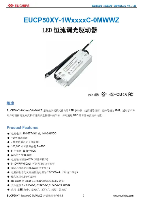
SHANGHAI EUCHIPS INDUSTRIAL CO.,LTDEUCP50XY-1WxxxxC-0MWWZProduct FeaturesLED 恒流调光驱动器概述EUCP50XY-1WxxxxC-0MWWZ 系列是恒流模式输出的LED 驱动器,抗浪涌等级高,防护等级为IP67,适用于户外。
用户可根据调光方式和市场需求选择相应的型号,并可通过NFC 编程器修改输出电流。
电源电压: 100-277VAC 或 141-391VDC 10kV 浪涌等级- 60℃低温启动(可选择) 100,000小时的寿命@ Tc=75C 5 年保修 @ Tc<=80C Airset TM NFC 编程电流输出精度+/-2% (可编程模型) 0-10V/PWM/DALI 可调光 (取决于型号) 调灭后待机功耗0.5W(取决于型号)电源控制器与风扇的辅助电源为12V 300mA (取决于型号) 输入过压保护(可选择)UL Class P , Class 2,ENEC/CB/CCC,SELV 认证 安全依据EN 61347-1, 61347-2-3,61347-2-13, 62384 应用 :LED 灯带、景观灯、工矿灯、路灯、泛光灯上海欧切斯实业有限公司型号清单 技术参数上海欧切斯实业有限公司注: 除非特别注明,所有的测试结果均在220VAC ,25℃室温下测得。
* 可选择标记项目,获取详细功能请联系销售人员调光安规/电磁兼容调调光光曲曲线线a. 带调灭功能默认值)b. 无调灭功能(联系销售获取此功能调光接线图(End of Life: Maximum Failure Rate=10%)使用寿命 vs. 外壳温度功率因数vs.负载THD vs.负载EUCP50NN(FR)-1WxxxxC-0MWWUUnspecified tolerance :±1AC INPUT(UL SJTW 3×18AWG)DC OUTPUT(UL SJTW 2×18AWG)BLACK(ACL)WHITE(ACN)GREEN(GND)RED(V+)BLUE(V-)效率 vs.负载 (1050mA)尺寸 (mm)EUCP50AR(AN)-1WxxxxC-0MWWUUnspecified tolerance :±1AC INPUT(UL SJTW 3×18AWG)DC OUTPUT(UL SJTW 2×18AWG)DIMMING WIRE(UL SJTW 2×18AWG)BLACK(ACL)WHITE(ACN)GREEN(GND)PURPLE(Vdim+)GRAY(Vdim-)RED(V+)BLUE(V-)EUCP50ER-1WxxxxC-0MWWUUnspecified tolerance :±1AC INPUT(UL SJTW 3×18AWG)DC OUTPUT(UL SJTW 2×18AWG)DIMMING WIRE(UL SJTW 3×18AWG)BLACK(ACL)WHITE(ACN)GREEN(GND)BLACK&WHITE(Vaux/+12V)PURPLE(Vdim+)GRAY(Vdim-)RED(V+)BLUE(V-)EUCP50DR-1WxxxxC-0MWWUUnspecified tolerance :±1AC INPUT(UL SJTW 3×18AWG)DC OUTPUT(UL SJTW 2×18AWG)DIMMING WIRE(UL 2464 4×22AWG)BLACK(ACL)WHITE(ACN)GREEN(GND)RED(V+)BLUE(V-)PINK(DALI 2)BLACK&WHITE(Vaux+)GRAY(Vaux-)BLUE&WHITE(DALI 1)EUCP50NN(FR)-1WxxxxC-0MWWSUnspecified tolerance :±1AC INPUT(VDE H05RN-F 3×1.0mm2)DC OUTPUT(VDE H05RN-F 2×1.0mm2)BROWN(ACL)BLUE(ACN)YELLOW&GREEN (GND)BROWN(V+)BLUE(V-)EUCP50AR(AN)-1WxxxxC-0MWWSUnspecified tolerance :±1AC INPUT(VDE H05RN-F 3×1.0mm2)DC OUTPUT(VDE H05RN-F 2×1.0mm2)DIMMING WIRE(H05RN-F 2×0.75mm2)BROWN(ACL)BLUE(ACN)YELLOW&GREEN (GND)PURPLE(Vdim+)GRAY(Vdim-)BROWN(V+)BLUE(V-)EUCP50ER-1WxxxxC-0MWWSUnspecified tolerance :±1AC INPUT(VDE H05RN-F 3×1.0mm2)DC OUTPUT(VDE H05RN-F 2×1.0mm2)DIMMING WIRE(H05RN-F 3×0.75mm2)BROWN(ACL)BLUE(ACN)YELLOW&GREEN (GND)BLACK&WHITE(Vaux/+12V)PURPLE(Vdim+)GRAY(Vdim-)BROWN(V+)BLUE(V-)EUCP50DR-1WxxxxC-0MWWSUnspecified tolerance :±1AC INPUT(VDE H05RN-F 3×1.0mm2)DC OUTPUT(VDE H05RN-F 2×1.0mm2)DIMMING WIRE(H05RN-F 4×0.5mm2)BROWN(ACL)BLUE(ACN)YELLOW&GREEN (GND)BROWN(V+)BLUE(V-)PINK(DALI 2)BLACK&WHITE(Vaux+)GRAY(Vaux-)BLUE&WHITE(DALI 1)。
白光LED的驱动器应能够支持LED光亮度的调节功能也就是所谓的led调光开关、pwm 调光开关技术。
目前调光技术主要有三种:PWM调光、模拟调光、以及数字调光。
市场上很多驱动器都能够支持其中的一种或多种调光技术。
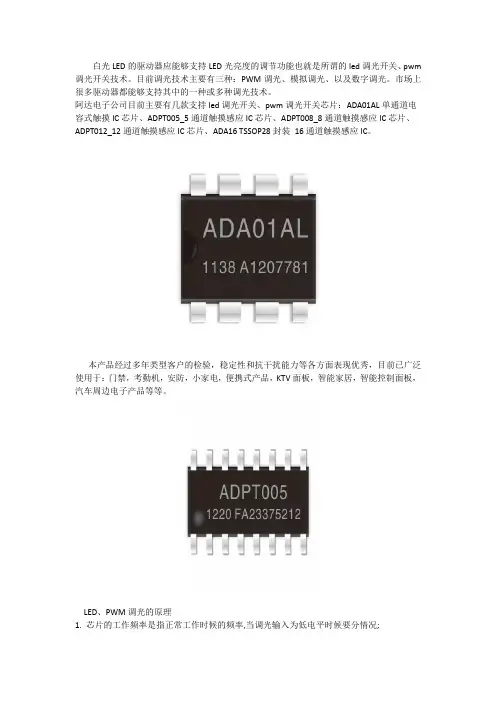
阿达电子公司目前主要有几款支持led调光开关、pwm调光开关芯片:ADA01AL单通道电容式触摸IC芯片、ADPT005_5通道触摸感应IC芯片、ADPT008_8通道触摸感应IC芯片、ADPT012_12通道触摸感应IC芯片、ADA16 TSSOP28封装16通道触摸感应IC。
本产品经过多年类型客户的检验,稳定性和抗干扰能力等各方面表现优秀,目前已广泛使用于:门禁,考勤机,安防,小家电,便携式产品,KTV面板,智能家居,智能控制面板,汽车周边电子产品等等。
LED、PWM调光的原理
1. 芯片的工作频率是指正常工作时候的频率,当调光输入为低电平时候要分情况;
2. LED恒流驱动如果是真正的PWM控制方式,则调光低电平来临的时候,恒流芯片不工作;
3. 当LED驱动为恒定开启时间,或者恒定关闭时间控制方法的时候,当调光低电平来临的时候,芯片还是会按照即定的频率来开关,但占空比会发生很大变化,即变的非常小
以上是我们为您整理阿达电子公司的部分PWM调光开关、LED调光开关芯片型号,更多详细资料请稳步到阿达官网资料下载或者产品中心进行更详细的查看。
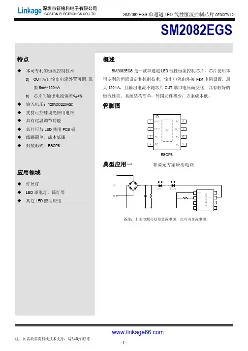
SM2082EGS内部功能框图管脚说明管脚序号管脚名称管脚说明1 GND 芯片地2 REXT 输出电流值设置端口7 OUT 电源输入与恒流输出端口3、4、5、6、8 NC 悬空脚订购信息订购型号封装形式包装方式卷盘尺寸管装编带SM2082EGS ESOP8 100000只/箱4000只/盘13寸极限参数若无特殊说明,环境温度为25°C。
符号说明范围单位V OUT OUT端口电压-0.5~450 VV REXT REXT端口电压-0.5~8 VRθJA注1PN结到环境的热阻65 °C/WT J工作结温范围-40~150 °CT STG存储温度-55~150 °CV ESD HBM人体放电模式>2 KV注1:散热表现与散热片尺寸、PCB厚度与层数息息相关。
实际应用条件下的热阻值会与测试值存在一定差异,使用者可选择适当的封装与PCB布局,以达到理想的散热表现。
电气工作参数若无特殊说明,环境温度为25°C。
符号说明条件最小值典型值最大值单位V OUT_MIN恒流拐点I OUT=30mA - - 6.5 VV OUT_BV OUT端口耐压- 450 - - VI OUT输出电流- 5- 120 mAI DD静态电流V OUT=10V,REXT悬空0.08 0.16 0.25 mAV REXT REXT端口电压V OUT=10V 0.58 0.6 0.62 VD IOUT IOUT片间误差I OUT=30mA - ±4 - %T SC电流负温度补偿起始点注2- - 150 - °C注2:电流负温度补偿起始点为芯片内部设定温度150℃。
OUT 端口输出电流特性SM2082EGS 的OUT 端口输出电流计算公式:(A))ΩRext(0.6VRext V I REXT OUT ==。
图1. SM2082EGS 输出电流与Rext 电阻关系曲线图2. SM2082EGS 恒流曲线图图3. SM2082EGS 输出电流温度特性注3注3:芯片焊接到2mm*2mm ,厚度为1mm 的铝基板上。
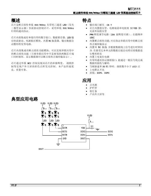
概述芯片是断点续传单线300/900ns归零码三通道 LED(发光二极管显示器)恒流驱动控制芯片,采用单线300/900ns 归零码通讯协议。
芯片内部集成有单线归零码数字接口、数据锁存器、LED输出恒流驱动、电源稳压模块、内置RC振荡器、输出数据自动整形转发等电路。
芯片内部集成有断点续传功能模块,可以实现串联应用中的断点续传功能(只要串联应用中不是相邻的两颗芯片端口同时损坏,显示数据都可以断点续传正确传输显示)。
芯片通过外围 MCU 控制实现该芯片的单独辉度、级联控制等实现户外大屏的彩色点阵发光控制。
本产品性能优良,质量可靠。
特点∙输出端口耐压 >26 V∙芯片内置稳压管,电源端需串电阻到 IC VDD 脚,无需外加稳压管∙PWM辉度调节电路(256 级辉度可调),扫描频率1KHZ∙内置断点续传功能,可以保证串联应用中的断点续传正确传输显示∙内置双 RC 振荡,并根据数据线上信号进行时钟同步,在接受完本单元的数据后能自动将后续数据进行整形转发∙内置上电复位电路∙归零码通讯协议级联接口,能通过一根信号线完成数据的接收与解码∙当刷新速率30帧/秒时,级联数不小于1024点∙上电默认不亮∙封装:DIP8、SOP8应用∙点光源∙护栏管∙软灯条∙户内外大屏等典型应用电路DIN2DIN1SOP8/DIP8封装管脚(800K传输速率断点续传功能)OUTR OUTG OUTB GNDVDDDIN2DIN1DOUT SOP8/DIP8极限参数推荐工作范围(无特殊说明,TA=-40~+85℃,GND=0V)电气参数开关特性内部框图DOUTVDD GND功能描述芯片采用单线归零码协议通讯传输。
芯片在上电复位以后,接收DIN 端口传输的数据,接受24 bit 后,DOUT 端口开始转发数据,提供下一个芯片的输入数据。
在转发之前,DOUT端口一直拉低。
此时芯片将不接收新的数据,芯片OUTR、OUTG、OUTB三个PWM输出口根据接收到的24 bit 数据,发出相应的不同占空比的信号,该信号周期在1 ms 左右。
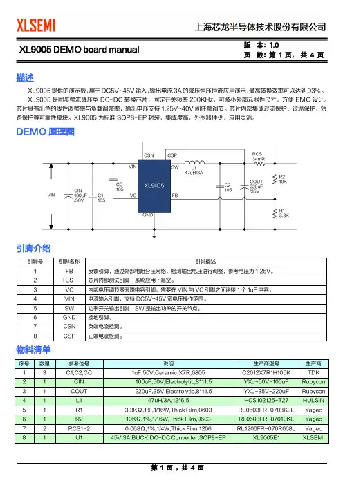
页数:第1 页,共4 页描述XL9005提供的演示板,用于DC5V~45V输入,输出电流3A的降压恒压恒流应用演示,最高转换效率可以达到93%。
XL9005是同步整流降压型DC-DC转换芯片,固定开关频率200KHz,可减小外部元器件尺寸,方便EMC设计。
芯片具有出色的线性调整率与负载调整率,输出电压支持1.25V~40V间任意调节。
芯片内部集成过流保护、过温保护、短路保护等可靠性模块。
XL9005为标准SOP8-EP封装,集成度高,外围器件少,应用灵活。
DEMO原理图引脚介绍物料清单页 数:第 2 页, 共 4 页DEMO 实物图实物图正面 实物图反面PCB 布局PCB 顶层截图 PCB 底层截图页 数:第 3 页, 共 4 页典型性能参数E f f i c i e n c y (%)Output current(A)O u t p u t v o l t a g e (V )Output current(A)5.0V 输出效率曲线 5.0V 输出线性调整率与负载调整率曲线瞬态负载响应波形瞬态负载响应波形(VIN=8V ,VOUT=5.0V ,IOUT=0至3A ) (VIN=12V ,VOUT=5.0V ,IOUT=0至3A )瞬态负载响应波形 瞬态负载响应波形(VIN=24V ,VOUT=5.0V ,IOUT=0至3A ) (VIN=36V ,VOUT=5.0V ,IOUT=0至3A )XL9005 DEMO board manual 版本:1.0页数:第4 页,共4 页应用信息输入电容选择在连续模式中,转换器的输入电流是一组占空比约为VOUT/VIN的方波。
为了防止大的瞬态电压,必须采用针对最大RMS电流要求而选择低ESR(等效串联电阻)输入电容器。
对于大多数的应用,1个100uF的输入电容器就足够了,它的放置位置尽可能靠近XL9005的位置上。
最大RMS电容器电流由下式给出:IRMS≈IMAX*√VOUT(VIN-VOUT)VIN其中,最大平均输出电流IMAX等于峰值电流与1/2 峰值纹波电流之差,即IMAX=ILIM-△IL/2。
YX009K3-RW 3按键五档带无级调光LED控制IC一、概述宇鑫科技:是一家专门服务于LED照明行业和消费电子产品行业的方案公司。
主要从事各类消费类电子产品控制方案芯片的研发与销售。
目前主要有:LED调光控制IC、分档调光IC、无级调光IC、调光调色温控制IC、移动电源控制IC、电量显示IC、应急灯控制IC、RGB七彩控制IC、红外遥控IC、定时控制IC、迷你风扇IC、及其他各类消费电子产品的专用控制IC等,主分:YX009K系列、YX017A系列、YX007系列、等都是公司自主研发与销售。
目前公司有近百款产品,若需选型手册,可联系客服索取,公司同时也根据用户不同需求进行针对性控制IC设计、销售和售后技术支持,本公司诚信经营,并热诚服务于不同规模公司的需求。
主要特点:1、芯片3按键控制方式,外围电路简单好用,可适用于LED台灯等调光控制*休眠微功耗设计,OFF状态时,芯片本身静态电流最低可小于1微安*点按5级分档步进调光*长按无级调光*PWM输出最大最小极限指示灯2、3按键方式控制逻辑如下:芯片每次上电默认为60%开机状态,后续调光记忆,直到掉电复位点按全程档位:20%-40%-60%-80%-100%点按或无级调光最大最小极限值:100%-20%OFF状态: 点按开关键-开机/点按开关键-关机 如此循环ON状态: 点按UP键-向上加20%,点按DOWN键-向下减20%ON状态: 长按UP键-向上无级调光/长按DOWN键-向下无级调光长按无级调光后,再点按,则是从当前值向上或向下20%这样步进3、 无级调光行程: 无级调光最大值与最小值之间的总行程时间是6秒左右4、 芯片驱动波形输出为31KHZ PWM,能实现平滑无闪烁调光,可直接驱动MOS管也可与支持高频调光的恒流芯片组合驱动,应用于各类灯具调光方案5、 调光极限值指示灯: 当PWM调到最大或最小值时,芯片6脚输出指示灯二、IC引脚功能说明三、 芯片引脚参考线路: (具体线路需工程师根据自己产品特点进行应用设计) 序号名称 功能说明 1V DD 电源+,2.5-5.0V 2UP “UP ”加按键 3DOWN “DOWN ”减按键 4ON/OFF “ON/OFF ”开关按键 5PWM 31KHZ调光PWM输出端口 6S ec 1 LED指示输出(调光极限值时,引脚输出高电平) 7IR NC 8 GND 电源地四、封装信息。
第二代调光LED线性驱动IC——RM903XRM903X是第二代调光LED线性驱动的最新成果。
它采用亚成微电子自有专利技术,充分实现恒流控制和效率优化。
与现有的驱动IC相比,RM903X具有更宽的电压适用范围和更高的效率,使用户的光源设计变得更加简单便捷。
第二代调光LED线性驱动IC的标志性特点是:高PF值、无频闪、支持调光。
采用RM903X 的方案可以做到PF值>0.8,几乎适应所有可控硅调光器,不需要去频闪电路即可做到任意亮度无频闪。
更简单、更稳定、更高效能,这是亚成微IC产品不懈的追求。
2014年,亚成微电子率先推出RM9005系列调光LED线性驱动,在业内掀起了线性驱动的新浪潮。
RM903X是亚成微以技术创新引领产品迭代的最新成果。
随着人们对健康光源的需求,RM903X系列必将成为新一代LED光源的首选方案。
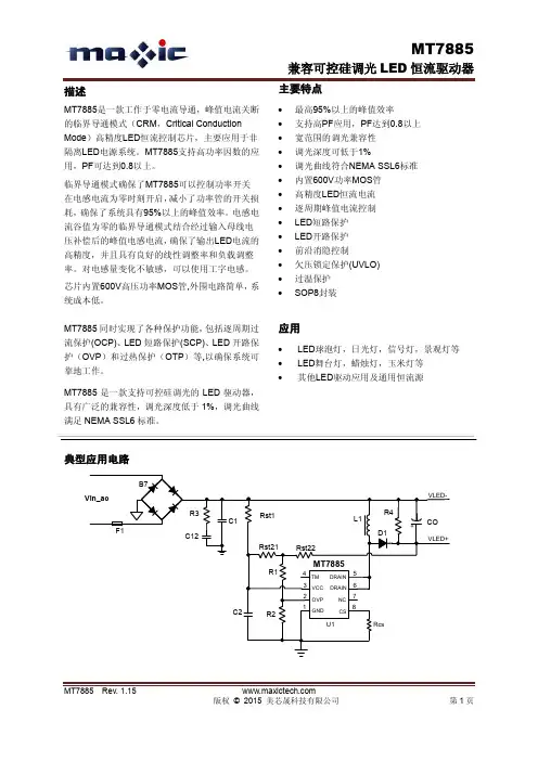
产品特点◆芯片可实现无频闪功能◆适应可控硅调光◆高PF值(PF>0.8)◆OTP过温保护点可调◆芯片应用无EMI 问题◆内置600V高压MOS◆不需要电感器件◆多芯片并联应用应用领域◆LED灯丝灯◆LED球泡灯◆LED筒灯/射灯◆LED可控硅调光应用典型方案A:RM9036A 120V 4W 灯丝灯方案/ 230V 8W灯丝灯方案B:RM9032A+RM9033A球泡灯方案9W 800lm调光频闪曲线EMI测试报告适应调光器列表RM903X和目前市面上调光IC优势对比:A:无频闪,完全满足欧美认证要求B:功率补偿功能,输入功率随电压变化更小C:恒流输出,光通量随输入电压变化更小D:可通过电阻调节温度保护点E:高性价比:低BOM成本、易规模化生产、高可靠性。
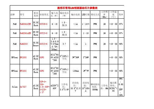
SM2082EK单通道LED恒流驱动控制芯片
概述:
SM2082EK是单通道LED恒流驱动控制芯片,芯片使用本司专利的恒流设定和控制技术,输出电流由外接Rext电阻设置为
5mA~60mA,且输出电流不随芯片OUT端口电压而变化,较好的恒流性能。
系统结构简单,外围元件极少,方案成本低。
特点:
本司专利的恒流控制技术
a)OUT端口输出电流外置可调,范围5mA~60mA
b)芯片间输出电流偏差小于±4%
输出AC电压:120V/220V
支持可控硅调光应用电路
具有过热保护功能
单颗芯片可做12W系统方案
芯片可与LED共用PCB板
线路简单、成本低廉
封装形式:ESOP8
应用领域:
T5/T8系列LED日光灯管
LED路灯照明应用
LED球泡灯,LED吸顶灯。
Instruction ManualP/N: 3015-9005Revision 2November 2017 Product Leadership ∙ Training ∙ Service ∙ ReliabilityNOTICE Specifications and information contained in this document may change without notice due to product improvements and enhancements.Bacharach, Inc. shall not be liable for errors contained herein or for incidental or consequential damages in connection with the furnishing, performance, or use of this material.No part of this document may be photocopied, reproduced, or translated to another language without the prior written consent of Bacharach, Inc.!WARNING: This product is considered to be Group 1 Class A equipment as defined by EN 55011 standards and is suitable for use in industrial environments. There may be potential difficulties in ensuring electromagnetic compatibility in other environments (e.g., domestic environments) due to conducted as well as radiated disturbances.Register your warranty by visitingCopyright © 2017, Bacharach, Inc.,all rights reserved. BACHARACH is a registered trademark of Bacharach, Inc. All other trademarks, trade names, service marks and logos referenced herein belong to their respective companies.Section 1. Overview1.1. IntroductionThe H-10 Pro is the most versatile, high performance leak detector available in the industry today. It detects refrigerants to pinpoint small, medium, and large leaks quickly and efficiently. Review this manual carefully and completely to assure satisfactory product performance and a long service life.1.2. Safety Warnings! WARNING: For your safety, DO NOT use this device to detect for leaks of refrigerants which are rated as combustible/flammable gases (e.g., ASHRAE A2- or A3-rated refrigerants).!HAZARDOUS AREA WARNING: This instrument has not been designed to be intrinsically safe for use in areas classified as hazardous locations. For your safety, DO NOT use it in hazardous (classified) locations.1.3. General Warnings!WARNING: This device is not to be used in any application that is beyond its intended purpose or beyond the scope of its specifications. For details on appropriate use, refer to the rest of this manual. Before risking equipment damage or personal injury, contact Bacharach if you are unsure of the validity of a particular application.!IMPORTANT:This analyzer is not intended to be used on a continuous basis.!WARNING:Except for replacement of consumables such as sensors, filters, and battery, this analyzer should only be opened and/or serviced by authorizedBacharach personnel. Failure to comply may void the warranty.!WARNING: Do not store instrument or its sensors with solvents or products that contain solvents.!IMPORTANT:Equipment Damage HazardsA.Submerging the probe in liquid willdamage the pump.B.Exposing the probe to pure refrigerantwill severely reduce the life or destroy the sensor. Life of the sensor is directly proportional to the amount of refrigerant that it is exposed to.C.Exposure to high concentrations ofrefrigerant may require adjustment of sensor heat. Refer to section 3.1.1.4. Specifications[1]Based on normal use. Consistent and/orconstant exposure to high levels of refrigerantwill deteriorate the sensor life more quickly.Increasing the sensor heater will also impactsensor life.[2]DO NOT use this device to detect for leaks ofrefrigerants which are rated as combustible/flammable gases (e.g., ASHRAE A2- or A3-ratedrefrigerants).[3]Sensitivity for R12, R22, R134a, R410a, R404a andR507 when unit is set to small leak setting,manual mode.[4]This warranty does not cover sensors, referenceleaks, filters, airflow balls, lamps, batteries, orprobe tips. This warranty does not coverdamages caused by the user.∇∇∇Section 2. Operation2.1. OverviewThe H-10 Pro sensor uses positive ion emission technology, commonly known as a heated diode. It is very sensitive to only halon substances (refrigerants) making this product highly resistive to false alarming, while retaining superior sensitivity for pinpointing the most difficult to find refrigerant leaks.A pump inside the unit draws air through the probe to the sensor. The presence of refrigerant(s) causes the H-10 Pro to sound a speaker and illuminate an LED in the probe. Sensitivity to pinpoint small, medium, and large leaks can be controlled by setting the Leak Size switch (see Section 2.2).2.2. Panel Controls2.3. Before First Use…Before you use the unit the first time: 1.Remove the sticky-label disc from thecap of the calibration reference bottle.This disc can be reused to help seal the vial when the leak detector is not in use, or it can be discarded. DO NOT attempt to unscrew the cap, you may damage the bottle. The calibration reference bottle should last approximately six months.2.With the Power switch in the OFFposition, charge the battery using the wall adapter. Charge time is 3-4 hours or until the Full Charge LED turns green.2.4. Adjusting the SensitivitySet the Leak Size switch as follows.SMALL switch position is the highest sensitivity. The unit will indicate leak rates of 0.006 oz/yr or greater and is used for fluorine-based (HFC) gases like R134a. This position also assures highest repeatability for locating 0.1 oz/yr (or greater) leaks per SAE J2791 moving probe test conditions. It must always be used to verify performance and calibration when using the calibration reference bottle.When using the small leak range position, a leak of HFC causing an audible signal equal to that produced by the leak vialhas a leak rate of approximately 0.5 oz/year.MEDIUM switch position is used for chlorine-based (CFC and HCFC) gases like R12 and R22. The medium setting will indicate approximately a 0.1 oz/yr (or greater) leak rate. This position supports finding leaks of approximately 0.5 oz/yr (per SAE J2791) or greater. It is also useful for locating larger HFC leaks.When using the medium leak range position on a CFC or HCFC system, this leak rate would also be approximately 0.5 oz/year.LARGE switch position is used to zero in on large leaks of any refrigerant. The large leak setting should be used in conjunction with manual mode.2.5. Auto Mode vs. Manual ModeAuto mode enables the H-10 Pro to block out background levels of refrigerants. This greatly reduces and/or eliminates false alarms while retaining sensitivity to quickly locate small or medium size leaks. Pinpointing leaks in this mode requires continuous probe movement.If the probe is held stationary over a leak, the unit will zero out the leak, going into the idle 1 tick/second condition. Briefly moving the probe away from the leak (1-2 seconds) permits the unit to re-establish sensitivity. Returning to the leak site, the unit will alarm again. Continuing thisprocedure will reliably and repeatedly pinpoint the leak with each pass over the leak site.If a large leak is present, the auto zero circuit may reduce sensitivity to an unacceptable level to find small and medium sized leaks. If this condition exists, use the manual mode to pinpoint a large leak. The manual mode is also an effective means to determine if a large leak of any refrigerant exists prior to searching for leaks (see Section 2.4).In Manual Mode the auto-zero circuit is disabled. The unit will not zero the leak if the probe is held over the leak site. This mode may require frequent readjustment of the Manual Balance control to maintain the required 1 tick per second that indicates proper adjustment and calibration for all three sensitivity switch positions. Manual mode provides greater sensitivity than auto mode.2.6. Setup1.Turn the unit on.2.Slide mode switch to AUTO position.3.Slide the sensitivity switch to theSMALL position.4.Check Low Battery LED. If it glows red,the battery needs charging, or youmay operate the unit using the supplied wall adapter.!NOTE: The sensor does not operate when the low battery LED is on.5.Check for sufficient airflow by pointingthe probe tip toward the floor, covering it with your finger, then releasing your finger. If proper flow exists, the red ball should noticeably rise up into the probe when you uncover the probe tip. Note that the actual height and final resting position of the red ball are not important. If the airflow ball does not rise:a.Tap the probe lightly to ensure theball is not sticking.b.Check the filter in the probe tip,per Section 4.1. If the flow is stillinsufficient, then the unit shouldbe sent for repair to the nearestAuthorized Service Center.6.Allow two minutes for the sensor towarm up, after which the flashing probe light and sound indicator will idle at approximately 1 click per second.7.Test operation by quickly touching theprobe tip to the top of the calibration reference bottle (make sure sticky label is removed). The unit should respond with a rapid flash rate and sound verifying correct operation and optimum sensitivity. If the unit does not respond correctly, see Section 3.1.2.7. Checking for Leaks! SAFETY WARNING: For your safety, DO NOT use this device to detect for leaks of refrigerants which are rated as combustible/flammable gases (e.g., ASHRAE A2- or A3-rated refrigerants). 1.Set the range switch to theappropriate range to ensuremaximum sensor life. If the leak sizeis unknown, start at the Large leaksetting. This protects the sensor if alarge amount of gas is present.!IMPORTANT:Exposing the sensorto large amounts of refrigerant orholding the probe over a leak for along period of time will significantlyshorten sensor life.2.Check for leaks in a logicalprogression through the entiresystem.3.If surfaces are dirty or wet, wipethem off with a clean, dry cloth toreduce filter clogging and extendsensor life. DO NOT allow the unit todraw in moisture. Use of the suppliedrubber probe tip helps preventmoisture from being drawn into theunit. Check for moisture beforeinserting the probe into areas to bechecked for leaks.4.If leaks have not been detected usingthe large leak setting: Try using themedium or small setting asappropriate.If leaks have been detected using thelarge leak setting: After locating andrepairing any leaks requiring the useof the LARGE switch setting, switchto the MEDIUM setting and verify thesystem is free of leaks. For HFCrefrigerants (such as R134a), verifythe system is leak free using theSMALL setting. For CFC and HCFCsystems (such as R12 and R22), theMEDIUM setting is typically sufficientto verify that the system is free ofleaks that require repairing.After a leak is located and repaired,clear the area with shop air, set theunit on the small leak sensitivity, anddouble check equipment for smallleaks.∇∇∇Section 3. Calibration andPerformance3.1. Heater AdjustmentsThe sensor heater circuit can be adjusted to control the sensitivity of the unit. A heat setting that is too high causes instability due to excessive sensitivity and shortens sensor life. A heat setting that is too low causes decreased sensitivity. The heater adjustment LEDs, heater adjustment, and calibration reference bottle is a unique system for setting the correct sensor heat (sensitivity) for optimum performance and long sensor life. To check the heater setting:1.Slide the mode switch to AUTO, slidethe leak switch to SMALL, turn ONthe unit and allow it to stabilize(approximately 2 minutes).2.When stabilized (at approximately 1click per second), briefly touch theprobe tip to the calibration referencebottle with the probe (ensure thesticky label disc is removed from thetop of the bottle.3.If adjusted properly, the red LOWLED will go out and the green OK LEDwill briefly glow. This indicates thesensor’s heat/sensitivity is adjustedfor optimum performance.If the red LOW LED remains on whenyou briefly touch the bottle, thesensor heat is set too low and theHeater Adjustment must be turnedslightly clockwise using a smallscrewdriver. Allow unit to stabilizeabout one minute and retest. Repeatthis procedure until the green OK LEDbriefly glows.If the red HIGH LED glows, the heat isset too high and the heateradjustment should be turned slightlycounterclockwise using a smallscrewdriver. Allow the unit tostabilize for about 1 minute and thenrepeat the test. Repeat thisprocedure until the proper green OKLED is indicated.!NOTE:After initial check for correct heater adjustment, disregard the calibration LEDs. Their indication is meaningless during subsequent leak testing activity.!NOTE:Check for proper heat adjustment on a daily basis. This assures the H-10 Pro is calibrated for the correct sensitivity for your daily test activity.!NOTE:Frequency of sensor heat adjustment is a function of how much exposure the sensor has to refrigerant. Adjustment may be required every couple of weeks for heavy duty service and once every few months for light duty service. !NOTE:Over the usable sensor life, when heater adjustment is fully clockwise and the green OK LED will not come on, it is time to replace the sensor. (See Section 4.3.)∇∇∇Section 4. Maintenance4.1. Replacing the FilterTo protect the pump from damage due to foreign particles and moisture, replace the filter as it becomes dirty. With moderate use (15 to 30 minutes a day), it is recommended that the filter be replaced once per month. In dirty environments or with heavy use, replace the filter more frequently. Always replace the filter when it is visibly dirty or wet. To replace the filter, follow the steps below.1.Remove the black rubber probe tip.2.Pick out the filter with a pin ortweezers. A fine screen will remain in the tip of the probe nozzle (behind where the filter sits).3.Insert the new filter in the probe tip.Make sure that the filter is firmly seated against the screen.4.Replace the rubber probe tip.4.2. Replacing the Airflow Indicator1.Remove the clear plastic section of theprobe tip by gently pulling and twisting.2.Turn the probe tip upside-down andtap on it to remove the old airflow indicator ball.3.Insert the new airflow indicator ballinto the tip.4.Reattach the probe tip to the probeassembly.4.3. Replacing the SensorThe sensor needs to be replaced when the H-10 Pro no longer responds to the calibration reference bottle, even with the heater adjustment turned fully clockwise (make sure the reference bottle contains some refrigerant).1.Turn the leak detector OFF.2.Turn the heater adjustment to itsfull counterclockwise position.3.Unplug the power cord and openthe sensor cover.4.Allow the sensor to cool beforetouching it.!WARNING: Sensor temperaturemay cause a burn if not allowed tocool.5.Unplug and discard the sensor.6.Insert a new sensor and close thesensor cover.7.Adjust the heater per Section 3.1.∇∇∇Section 5. Troubleshooting 5.1. Diagnosing IssuesP=Problem C/S=Cause/Solution(s) P No response to calibration reference bottle.C/S Heat Adjustment is set too low or bottle is empty. Readjust heater (see“Heater Adjustment” section) orreplace bottle (3015-0864).No air flow (indicator ball in probedoesn’t float). Replace filter in probetip (3015-0784). Check for properpump operation.Sensor exposed to excessive amountsof halogen gas. Move probe to cleanatmosphere for several minuteswhile sensor purges itself.Water is in the probe. Turn unit offand disconnect probe from chassis.Remove screws and take out chassis.Look at the underside of the leakdetector and follow the probe to thepump. Remove this hose from thepump. Blow clean air (5 psi) into theprobe tip for one or two minutes.Reassemble unit and replace thefilter (3015-0784).P Erratic response occurs in all leak positions.C/S Filter is clogged. Replace the filter (3015-0784).Dirt is in the sensor. Remove sensorand blow it out with clean air (notover 10 psi). If unsuccessful, replacethe sensor (3015-0486). Replace thefilter (3015-0784).Sensor has a short circuit. Replacesensor (3015-0486).Atmosphere is contaminated withexcessive refrigerant gas. Ventilatethe area.P Response is continuous (especially in SMALL leak switch position).C/S Detector sensitivity is excessive.Readjust heater (see “HeaterAdjustment” section).5.2. Limited WarrantyThe purchaser is warranted that this leak detector will be free of defects in material and workmanship for 3 years from date of purchase. This warranty does not cover sensors, reference leaks, filters, airflow balls, lamps, batteries, or probe tips. Damages caused by the user will not be covered.If any defects are discovered during the warranty period, an Authorized Service Center will repair or replace the unit at their option. The foregoing limited warranty is exclusive and in lieu of all other warranties, whether written or implied, and no warranty of merchantability or fitness for purpose will apply.5.3. Repair InformationShould it become necessary to repair your H-10 Pro, please contact an authorized service center. Units should be carefully packed to prevent shipping damage and shipped prepaid.5.4. Spare Parts5.5. Authorized Service Centers Replacement parts and service can be obtained by contacting one of the following Bacharach Service Centers.United StatesBacharach, Inc.621 Hunt Valley CircleNew Kensington, PA 15068Phone: 724-334-5051Fax: 724-334-5723Email: ******************** CanadaBacharach, Inc.10 West Pearce Street, Unit 4 Richmond Hill, Ontario L4B 1B6CanadaPhone: 905-470-8985Fax: 905-470-8963Email: ******************∇∇∇Bacharach, Inc.621 Hunt Valley CircleNew Kensington, PA 15068 USA Phone: 724-334-5000 • Fax: 724-334-5001 Toll Free: 1-800-736-4666Website: E-mail:********************。