故障代码及故障定义
- 格式:xls
- 大小:82.50 KB
- 文档页数:2
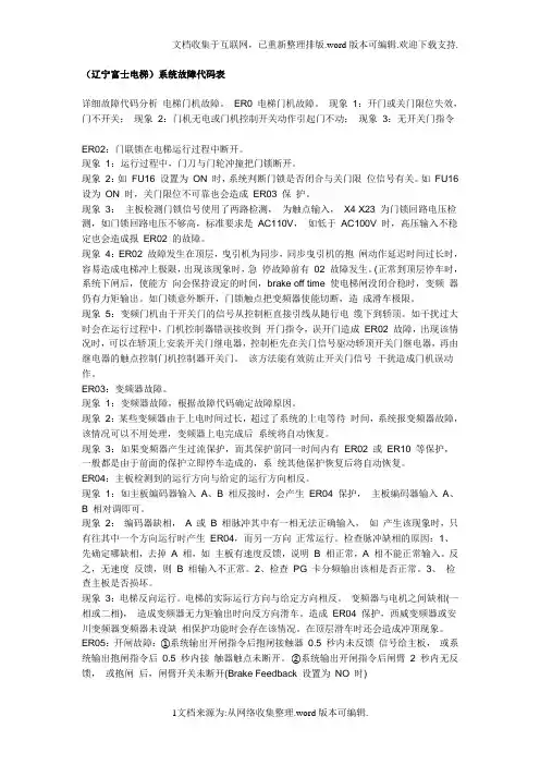
(辽宁富士电梯)系统故障代码表详细故障代码分析电梯门机故障。
ER0 电梯门机故障。
现象1:开门或关门限位失效,门不开关;现象2:门机无电或门机控制开关动作引起门不动;现象3:无开关门指令ER02:门联锁在电梯运行过程中断开。
现象1:运行过程中,门刀与门轮冲撞把门锁断开。
现象2:如FU16 设置为ON 时,系统判断门锁是否闭合与关门限位信号有关。
如FU16 设为ON 时,关门限位不可靠也会造成ER03 保护。
现象3:主板检测门锁信号使用了两路检测,为触点输入,X4 X23 为门锁回路电压检测,如门锁回路电压不够高,标准要求是AC110V,如低于AC100V 时,高压输入不稳定也会造成报ER02 的故障。
现象4:ER02 故障发生在顶层,曳引机为同步,同步曳引机的抱闸动作延迟时间过长时,容易造成电梯冲上极限,出现该现象时,急停故障前有02 故障发生。
(正常到顶层停车时,系统下闸后,使能方向会保持设定的时间,brake off time 使电梯闸没闭合稳时,变频器仍有力矩输出。
如门锁意外断开,门锁触点把变频器使能切断,造成滑车极限。
现象5:变频门机由于开关门的信号从控制柜直接引线从随行电缆下到轿顶。
如干扰过大时会在运行过程中,门机控制器错误接收到开门指令,误开门造成ER02 故障,出现该情况时,可以在轿顶上安装开关门继电器,控制柜先在关门信号驱动轿顶开关门继电器,再由继电器的触点控制门机控制器开关门。
该方法能有效防止开关门信号干扰造成门机误动作。
ER03:变频器故障。
现象1:变频器故障,根据故障代码确定故障原因。
现象2:某些变频器由于上电时间过长,超过了系统的上电等待时间,系统报变频器故障,该情况可以不用处理,变频器上电完成后系统将自动恢复。
现象3:如果变频器产生过流保护,而其保护前同一时间内有ER02 或ER10 等保护,一般都是由于前面的保护立即停车造成的,系统其他保护恢复后将自动恢复。
ER04:主板检测到的运行方向与给定的运行方向相反。
所在位置:技术中心---三洋空调故障代码---TCL空调故障代码一、KF(R)-34GW/E5:故障代码故障原因E1 室温热敏电阻短路或断路E2 室内管温热敏电阻短路或断路E3 室外管温热敏电阻短路或断路E4 控制器连续16秒未接到转速反馈信号E7 压缩机保护(压缩机连续运行7分钟,室内管温与室温相差在3℃以内时)二、KFR-25GW/JK2,KFR-34GW/JK2故障点故障显示症状验证方法检修接错线● ○●○●○●○重复亮1秒,灭1秒室外机不运转接通电源,继电器52C首次接通后,连续信号停止4~5秒☆检查连接导线☆检查室内机控制板☆检查室外机控制板☆检查电器部件连接信号● ○○○○○●○○○○○●○鹬馗戳?秒,灭2.5秒来自室外机的连续信号停止4~5秒管温、室温热敏电阻● ○●○○○○○●○●○○重复闪2次,灭2.5秒室外机不运转运行中将室温或管温电阻短路或开路2秒钟☆检查热敏电阻☆检查插座☆检查室内电路板室内风扇电机● ○●○●○○○○○●○●○●○○○重复闪3秒,灭2.5秒室内风扇重复出现转12秒停3分钟,风扇不运转在室内风扇电机运转12秒期间,不能发射转速反馈信号☆拔下插座CN211,测量CN121②-③之间,确认信号大于等于1.5V☆检查室内控制板☆检查室内风机☆检查插座室外化霜电阻● ○●○●○●○●○●○○○○○●○重复闪6秒,灭2.5秒室外机不运转压缩机起动后,除霜电阻接通或断开☆制冷量不足☆检查除霜电路板● :表示亮;○:表示灭三、KF-25GW/JK2,KF-35GW/JK2故障点故障显示症状验证方法检修管温、室温热敏电阻● ○●○○○○○●○●○○重复闪2次,灭2.5秒室外机不运转运行中将室温或管温电阻短路或开路2秒钟☆检查热敏电阻☆检查插座☆检查室内电路板室内风扇电机● ○●○●○○○○○●○●○●○○○重复闪3秒,灭2.5秒室内风扇重复出现转12秒停3分钟,风扇不运转在室内风扇电机运转12秒期间,不能发射转速反馈信号☆拔下插座CN211,测量CN121②-③之间,确认信号大于等于1.5V☆检查室内控制板☆检查室内风机☆检查插座四KFR-51LW/Aa2, KFR-51LW/Ba2故障显示部位故障部位原因解决措施27℃灯闪烁室外机结霜保护☆空气循环不畅☆室内机风扇电机不工作☆移去联物或清洗滤网☆检查室内风扇电机28℃灯闪烁室外机组☆室内、外机连接线错误☆检查接线☆检查室外机29℃灯闪烁管温热敏电阻☆插头接触不良☆热敏电阻陨坏☆检查接线☆检查热敏电阻☆检查室内控制板30℃灯闪烁室温热敏电阻☆插头接触不良☆热敏电阻陨坏☆检查接线☆检查热敏电阻☆检查室内控制板五:KFR-75LW/(S)2,KFR-120LW/(S)a2KFR-75LW/(S)2, KFR-120LW/(S)a2(1) 自检(以下指示灯闪烁)TUNER TEMP▽▽故障部位原因检修方法12—29室外机组☆室内、外机接线错误☆室外机检测到异常状态☆室外管温热敏电阻☆检测到反转相位☆检查接线☆检查室外机☆检查室外管温电阻11——28室温热敏电阻☆插头接触不良☆热敏电阻失灵☆检查接线☆检查热敏电阻☆检查室内控制板10——27室内管温热敏电阻☆插头接触不良☆热敏电阻失灵☆检查接线☆检查热敏电阻☆检查室内控制板7——24预防铜管结霜和过热☆空气循环不畅☆室内机风扇电机不工作☆移去障碍物或清洗滤网☆检查室内风扇电机(1——18亮表示空调正处于自检状态)(2)室外机故障代码闪烁的LED异常诊断原因检查方法LD1反相R、S和相接触不良检查电源输送电路LD2缺相☆S相断开☆电源接触时保护器触点断开☆检查电源输送电路☆检查各保护器LD3室外管温电阻异常(断路或短路)☆室外热敏电阻损坏☆热敏电阻接触不良☆检查热敏电阻☆检查插头和控制板LD4高压开关(63H2)☆高压开头接触不良☆高压开关发生作用☆检查高压开关和室外风扇电机☆制冷剂是否不足☆空气循环是非不畅LD5热继电器(51C)☆热继电器接触不良☆热敏电阻继电器工作☆检查热继电器、压缩机和电源LD6温度开关(26C)☆温度开关接触不良☆温度开关工作☆检查温度开关☆检查制冷剂是否充足☆毛细管是否阻塞LD7过热保护☆热敏电阻损坏☆管温超过67℃☆检查热敏电阻☆检查室外风扇电机☆检查空气循环是否受阻LD8室外控制板输入电路异常脉冲输入不正常检查室外机控制板六:KF-34JK3,KF-34GW/JK3, KFR-34GW/JK3室内管温传感器●○●○○○○○●○●○室内管温短路或断路1.5秒2.5秒室温传感器●○○○○○室内温传短路或断路2.5秒室内风扇●○●○● ○○○○○●○●○● 单片机12秒未接到转速反馈信号2.5秒2.5秒七:KFR-32GW /(B)1 23JK1 25JK故障定时灯(黄色)运行灯(绿色)室内机盘管温度传感器断亮闪亮1次/8秒室温传感器断亮闪亮2次/8秒室外机异常闪亮5次/8秒亮防结霜闪亮4次/8秒亮防冷风、化霜闪亮1次/2秒八: KFR-23JK5KF(R)-23GW/JK51、压缩机连续工作时间≥10min,盘管温度≥房间温度-5℃,转低速≥5min后仍盘管温度≥房间温度-5℃,则关闭空调。
FR-A540变频器的操作-故障处理常见故障代码常见故障代码定义操作面板显示:E.OC1 FR-PU04 OC During Acc名称:加速时过电流断路内容:加速运行中,当变频器输出电流超过额定电流的200%时,保护回路动作,停止变频器输出。
仅给R1、S1端子供电,输入起动信号时,也为此显示检查要点:是否急加速运转输出是否短路主回路电源(R、S、T)是否供电处理:延长加速时间起动时,“E.OC1”总是点亮的情况下,拆下电动机再起动。
如果“E.OC1”仍点亮,请与经销商或本公司营业所联系主回路电源(R、S、T)供电操作面板显示:E.OC2 FR-PU04 Stedy Spd OC名称:定速时过电流断路内容:定速运行中,当变频器输出电流超过额定电流的200%时,保护回路动作,停止变频器输出检查要点:负荷是否有急速变化,输出是否短路处理:取消负荷的急速变化操作面板显示:E.OC3 FR-PU04 OC Dur ing Dec名称:减速时过电流短路内容:减速运行中(加速、定速运行之外),当变频器输出电流超过额定电流的200%时,保护回路动作,停止变频器输出检查要点:是否急减速运转,输出是否短路,电动机的机械制动是否过早处理:延长减速时间,检查制动动作操作面板显示:E.THM FR-PU04 Motor Over load名称:电动机过负荷断路(电子过流保护)内容:过负荷以及定速运行时,由于冷却能力的低下,造成电动机过热,变频器的内置电子过流保护检测达到设定值的85%时,予报警(显示TH),达到规定值时,保护回路动作,停止变频器输出。
多极电动机或两台以上电动机运行时,电子过流保护不能保护电动机,请在变频器输出侧安装热继电器检查要点:电动机是否在过负荷状态下使用处理:减轻负荷。
恒转矩电动机时,把Pr.71设定为恒转矩电动机操作面板显示:E.THT FR-PU04 Lnv. Over load名称:变频器过负荷断路(电子过流保护)内容:如果电流超过额定电流的150%,而未到过电流切断(200%以下)时,为保护输出晶体管,用反时限特性,使电子过流保护动作,停止变频器输出(过负荷承受能力150%60s)检查要点:电动机是否有过负荷状态下使用处理:减轻负荷操作面板显示:E.IP FR-PU04 Inst.Pwr.Loss名称:瞬时停电保护内容:停电超过15ms(与变频器输入切断一样)时,为防止控制回路误动作,瞬时停电保护功能动作,停止变频器输出。
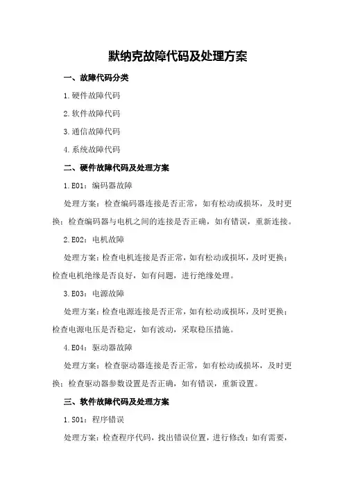
默纳克故障代码及处理方案一、故障代码分类1.硬件故障代码2.软件故障代码3.通信故障代码4.系统故障代码二、硬件故障代码及处理方案1.E01:编码器故障处理方案:检查编码器连接是否正常,如有松动或损坏,及时更换;检查编码器与电机之间的连接是否正确,如有错误,重新连接。
2.E02:电机故障处理方案:检查电机连接是否正常,如有松动或损坏,及时更换;检查电机绝缘是否良好,如有问题,进行绝缘处理。
3.E03:电源故障处理方案:检查电源连接是否正常,如有松动或损坏,及时更换;检查电源电压是否稳定,如有波动,采取稳压措施。
4.E04:驱动器故障处理方案:检查驱动器连接是否正常,如有松动或损坏,及时更换;检查驱动器参数设置是否正确,如有错误,重新设置。
三、软件故障代码及处理方案1.S01:程序错误处理方案:检查程序代码,找出错误位置,进行修改;如有需要,重新编译程序。
2.S02:软件版本不匹配处理方案:检查软件版本,升级或降级至与设备兼容的版本;如有需要,重新安装软件。
3.S03:系统文件损坏处理方案:备份重要数据,重新安装系统;如有需要,使用专业工具修复损坏的系统文件。
四、通信故障代码及处理方案1.C01:通信故障处理方案:检查通信线路是否正常,如有松动或损坏,及时更换;检查通信协议是否正确,如有错误,重新设置。
2.C02:网络故障处理方案:检查网络连接是否正常,如有问题,重新连接;检查网络设置是否正确,如有错误,重新设置。
3.C03:设备冲突处理方案:检查设备地址是否冲突,如有冲突,重新分配地址;检查设备之间的连接是否正确,如有错误,重新连接。
五、系统故障代码及处理方案1.B01:系统错误处理方案:检查系统设置,找出错误位置,进行修改;如有需要,重新安装系统。
2.B02:系统升级失败处理方案:备份重要数据,重新执行升级操作;如有需要,联系技术支持。
3.B03:系统恢复失败处理方案:检查恢复文件是否完整,如有损坏,重新获取恢复文件;按照恢复指南进行操作。
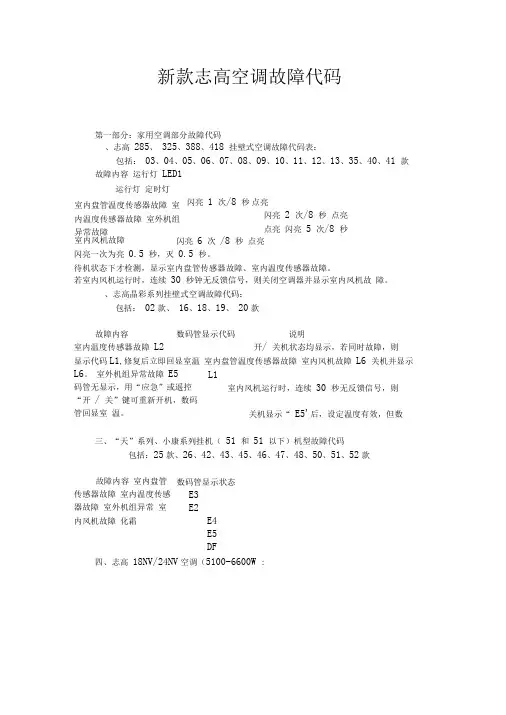
新款志高空调故障代码第一部分:家用空调部分故障代码、志高 285、 325、388、418 挂壁式空调故障代码表:包括: 03、04、05、06、07、08、09、10、11、12、13、35、40、41 款 故障内容 运行灯 LED1运行灯 定时灯闪亮 1 次/8 秒点亮 闪亮 2 次/8 秒 点亮 点亮 闪亮 5 次/8 秒闪亮一次为亮 0.5 秒,灭 0.5 秒。
待机状态下才检测,显示室内盘管传感器故障、室内温度传感器故障。
若室内风机运行时,连续 30 秒钟无反馈信号,则关闭空调器并显示室内风机故 障。
、志高晶彩系列挂壁式空调故障代码: 包括: 02款、 16、18、19、 20款 故障内容数码管显示代码说明室内温度传感器故障 L2开/ 关机状态均显示,若同时故障,则显示代码L1,修复后立即回显室温 室内盘管温度传感器故障 室内风机故障 L6 关机并显示L6。
室外机组异常故障 E5码管无显示,用“应急”或遥控“开 / 关”键可重新开机,数码管回显室 温。
三、“天”系列、小康系列挂机( 51 和 51 以下)机型故障代码包括:25款、26、42、43、45、46、47、48、50、51、52款故障内容 室内盘管传感器故障 室内温度传感器故障 室外机组异常 室内风机故障 化霜四、志高 18NV/24NV 空调(5100-6600W :室内盘管温度传感器故障 室内温度传感器故障 室外机组异常故障室内风机故障闪亮 6 次 /8 秒 点亮L1室内风机运行时,连续 30 秒无反馈信号,则关机显示“ E5'后,设定温度有效,但数数码管显示状态E3 E2E4 E5 DF示闪亮一次为:亮 0.5 秒,灭 0.5 秒。
如闪亮 2 次 /4 秒为:亮 0.5 秒,灭 0.5 秒 ,亮 0.5 秒,灭 0.5 秒 ,停 2 秒,一个周期共 4 秒,如此循环。
对于非变频 机,以下有关灯闪烁的解释不再重复。

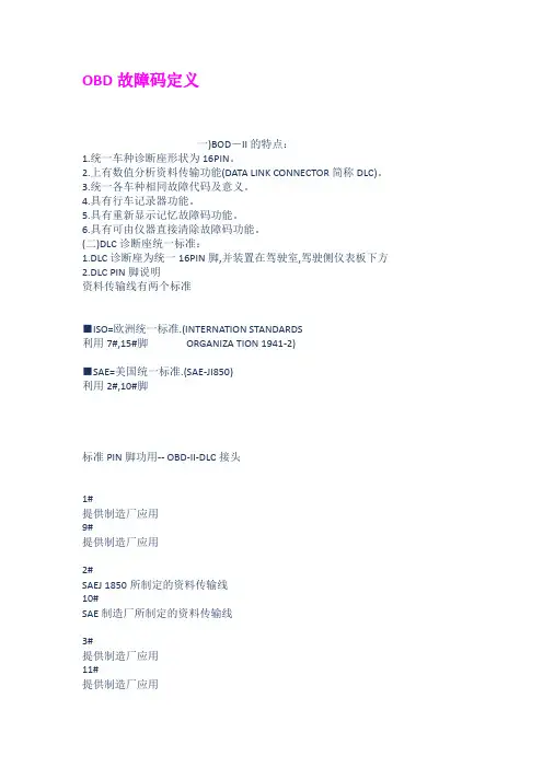
OBD故障码定义一)BOD-II的特点:1.统一车种诊断座形状为16PIN。
2.上有数值分析资料传输功能(DATA LINK CONNECTOR简称DLC)。
3.统一各车种相同故障代码及意义。
4.具有行车记录器功能。
5.具有重新显示记忆故障码功能。
6.具有可由仪器直接清除故障码功能。
(二)DLC诊断座统一标准:1.DLC诊断座为统一16PIN脚,并装置在驾驶室,驾驶侧仪表板下方2.DLC PIN脚说明资料传输线有两个标准■ISO=欧洲统一标准.(INTERNATION STANDARDS利用7#,15#脚ORGANIZA TION 1941-2)■SAE=美国统一标准.(SAE-JI850)利用2#,10#脚标准PIN脚功用-- OBD-II-DLC接头1#提供制造厂应用9#提供制造厂应用2#SAEJ 1850所制定的资料传输线10#SAE制造厂所制定的资料传输线3#提供制造厂应用11#提供制造厂应用4#直接车身搭铁12#提供制造厂应用5#信号回路搭铁13#提供制造厂应用6#提供制造厂应用14#提供制造厂应用7#ISO-9141-2所制定的资料传输线K15#ISO-9141-2所制定的资料传输线L8#提供制造厂应用16#直接电瓶正电源3.自1990年11月SAE定订J2054号通报-- 「诊断资料通讯标准」制定了14 个模式,简称为(DTM)-- DIAGNOSTIC TEST MODES.SAE-J2054号通报中制定的14个诊断通讯模式模式功能模式功能回到正常模式7数值指令显示传输诊断资料8切断正常传输2记忆资料清除9连接正常传输3检测RAM资料10清除故障记忆4元件控制功能11暂停正常传输5RAM资料下载12依数值位置定义诊断6RAM资料修改13依记忆内码定义诊断4.在1991年12月SAE定订J1979号通报,并在1994年6月修定该通报为-- 「诊断测试模式标准」即为OBD系统(联邦)及OBD-II系统(加州)-- ON--BOARD DIAGNOSTIC,制定7个模式,简称为(OBDOBD-II)SAE-J1979号通报中制定的7个诊断测试模式MODE $01-◎目前引擎诊断数值需求◎类比输入输出信号◎数值输入输出信号◎系统状态资讯◎综合计算数据值MODE $03 废气相关的引擎诊断[模式3] 故障码MODE $04 废气相关的诊断系统[模式4] 清除与归零CODE $05 含氧传感器监控测试[模式5] 结果MODE $02-◎目前引擎瞬间数值需求◎类比输入输出信号◎数位输入输出信号◎系统状态资讯◎综合计算数据值MODE $06 电脑监控非连续性[模式6] 测试结果MODE #07 电脑监控连续性测试[模式7] 结果5.在1993年6月SAE定订J2190号通报-- 「加强诊断测试标准」该通报依据J1979号通报(诊断测试模式标准)之增订文件,并适用于「诊断通讯方面」SAE -J1850或ISO 9141-2标准。
天行健,君子以自强不息;地势坤,君子以厚德载物;行盛于言。
一箪食,一飘饮,在陋巷,人不堪其忧,回也不改其乐。
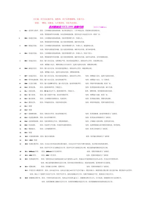
苏州默纳克NICE-3000故障代码海纳百川.2009.12.1.1.E01—逆变单元保护。
原因:主回路输出接地或短路;曳引机连线过长;工作环境过热;控制器内部连线松动。
处理:排除接线等外部问题;加电抗器或滤波器;检查风道与风扇是否正常;联系厂家。
2.E02—加速过电流。
原因:主回路输出接地或短路;电机参数调谐与否;负载太大。
处理:排除接线等外部问题;进行电机参数调谐;减轻突加负载。
3.E03—减速过电流。
原因:主回路输出接地或短路;电机参数调谐与否;负载太大;减速曲线太陡。
处理:排除外部接线等问题;进行电机参数调谐;减轻突加负载;调节曲线参数。
4.E04—恒速过电流。
原因:主回路输出接地或短路;电机参数调谐与否;负载太大;码盘干扰大。
处理:排除接线等外部问题;进行电机参数调谐;减轻突加负载;选择合适码盘,采用屏蔽线连接。
5.E05—加速过电压。
原因:输入电压过高;电梯倒拉严重;制动电阻选择偏大,或制动单元异常;加速曲线太陡。
处理:调整输入电压;调整电梯运行启动时序;选择合适制动电阻;调整曲线参数。
6.E06—减速过电压。
原因:输入电压过高;制动电阻选择偏大;或制动单元异常;减速曲线太陡。
处理:调整输入电压;选择合适制动电阻;调整曲线参数。
7.E07—恒速过电压。
原因:输入电压过高;制动电阻选择偏大,或制动单元异常。
处理:调整输入电压;选择合适制动电阻。
8.E08—控制电源故障。
原因:输入电压过高;驱动控制板异常。
处理:调整输入电压;与厂家联系。
9.E09—欠电压故障。
原因:输入电源瞬间停电;输入电压过低;驱动控制板异常。
处理:排除外部电源问题;联系厂家。
10.E10—系统过载。
原因:抱闸回路异常;负载过大。
处理:检查抱闸回路及电源;减小负载。
11.E11—电机过载。
原因:FC-02设定不当;抱闸回路异常;负载过大。
美的空调故障代码获取更多故障代码,请回复相关空调品牌。
例如:回复“格力”、“美的”;即可查询对应品牌空调的故障代码。
E系列、M系列、H系列、G系列直流变频挂机E0-EEPROM参数错误指示E1-室内机和室外机通信故障E2-过零检测出错E3-风机速度失控E4-温度保险丝断开保护E5-室外温度传感器故障E6-室内温度传感器故障P0-模块保护P1-电压过高或过低保护P2-压缩机顶部温度保护P4-直流变频压缩机位置保护N系列、W系列直流变频挂机E0-EEPROM参数错误指示E1-室内机和室外机通信故障E2-过零检测出错E3-风机速度失控E4-温度保险丝断开保护E5-室外温度传感器故障或室外807EEPROM故障E6-室内温度传感器故障P0-模块保护P1-电压过高或过低保护P2-压缩机顶部温度保护P4-直流变频压缩机位置保护C系列全直流变频挂机E1-EEPROM参数错误指示E2-室内机和室外机通信故障E3-过零检测出错E4-风机速度失控E5-室外温度传感器故障或室外E方参数故障E6-室内温度传感器故障E7-室外风机速度失控故障E8-显示板通信故障E9-IPM模块故障P0-模块保护P1-电压过高或过低保护P2-压缩机顶部温度保护P3-室外温度过低保护P4-直流变频压缩机位置保护I系列直流变频挂机E0-EEPROM参数错误指示E1-室内机和室外机通信故障E2-过零检测出错E3-风机速度失控E5-室外温度传感器故障或室外E方参数故障E6-室内温度传感器故障E7-室外风机速度失控故障E8-除尘复位故障P0-模块保护P1-电压过高或过低保护P2-压缩机顶部温度保护P3-室外温度过低保护P4-直流变频压缩机位置保护J、K、L、R、K(太阳能)系列直流变频挂机E0-EEPROM参数错误指示E1-室内机和室外机通信故障E2-过零检测出错E3-风机速度失控E5-室外温度传感器故障或室外E方参数故障E6-室内温度传感器故障E7-室外风机速度失控故障E8-模式冲突P0-模块保护P1-电压过高或过低保护P2-压缩机顶部温度保护P3-室外温度过低保护P4-直流变频压缩机位置保护50FBPY、50BPY变频柜机E01-一个小时四次模块保护E03-一个小时三次排气温度保护P01-室内板与室外板2分钟通讯不上保护P02-IPM模块保护P03-高低电压保护P04-室内温度传感器开路或短路(房间、温度)P05-室外温度传感器开路或短路(高温或低温)P06-室内蒸发器温度保护关压缩机(高温或低温)P07-室外冷凝器高温保护关压缩机P09-室外排气温度过高关压缩机P10-压缩机顶部温度保护P11-化霜或防冷风P12-室内风机温度过热P13-室内板与开关板3分钟通讯不上美的系列侧出风嵌入式空调器E0-上电时读EEPROM参数出错E1-室内房间温度T1传感器开路或短路E2-室内蒸发器温度T2传感器开路或短路E3-冷凝器温度T3传感器开路或短路Pd-四次电流保护P系列分体机E1-上电时读EEPROM参数出错E2-过零检测出错E3-风机速度失控E4-四次电流保护E5-室内房间温度传感器开路或短路E6-室内蒸发器温度传感器开路或短路E8-过滤网复位故障Q系列E1-T1传感器故障E2-T2传感器故障E3-T3传感器故障E4-T4传感器故障E5-网络通信故障E6-室外保护E7-加湿器故障E8-静电除尘故障E9-EEPROM出错5匹柜机系列新电控方案E1-T1传感器故障E2-T2传感器故障E3-T3/T4传感器故障E4-T4传感器故障E5-室内外通信故障E10-压缩机低压故障E13-压缩机缺相故障E14-压缩机相序反接故障R型交流变频系列、S型交流变频系列、V型交流变频分体机系列E0-EEPROM参数错误指示E1-室内机和室外机通信故障E2-过零检测出错E3-风机速度失控E4-温度保险丝断开保护E5-室外温度传感器故障E6-室内温度传感器故障P0-模块保护P1-电压过高或过低保护P2-压缩机顶部温度保护U型全直流变频、V型全直流变频分体机系列E0-EEPROM参数错误指示E1-室内机和室外机通信故障E2-过零检测出错E3-风机速度失控E4-温度保险丝断开保护E5-室外温度传感器故障E6-室内温度传感器故障E7-室外风机速度失控(V型全直流变频)P0-模块保护P1-电压过高或过低保护P2-压缩机顶部温度保护P3-室外温度过低保护(预留)P4-压缩机位置检测故障E2系列、E3系列、DC系列、DE系列、HA系列、F系列、I系列、G系列、GC系列、IA系列、IB系列柜机T1-传感器故障E2-T2传感器故障E3-T3传感器故障E4-T4传感器故障E5-负载板与显示板通信故障E8-室内外通信故障E9-开关门故障EA-压缩机低压故障Eb-室内直流风机失速Ed-压缩机缺相故障EE-压缩机相序反接故障PAU-进风格栅保护S1、S2、S3、S6型系列、Q1、Q2、Q3系列、U(U1)系列、、P系列、K系列柜机、V系列、J系列、R系列柜、V2系列、W系列、GA系列、N系列T1-传感器故障E2-T2传感器故障E3-T3/T4传感器故障E4-T4传感器故障(变频机用)E5-网络通信故障E6-室外故障E7-加湿器故障E8-静电除尘故障E9-自动门故障PAU-进风格栅保护Q1系列、Q2系列、Q3系列、U系列、V系列、J系列、V1系列、N系列、X系列、GA系列、、V1系列、H系列、A系列、B系列、K系列、W系列、FA系列、FB系列、FC系列、HA系列、HB 系列、GC系列分体机E1-上电时读EEPROM参数出错E2-过零检测出错E3-风机速度失控E4-四次电流保护E5-室内房间温度传感器开路或短路E6-室内蒸发器温度传感器开路或短路。
SAE Technical Standards Board Rules provide that: “This report is published by SAE to advance the state of technical and engineering sciences. The use of this report is entirely voluntary, and its applicability and suitability for any particular use, including any patent infringement arising therefrom, is the sole responsibility of the user.”SAE reviews each technical report at least every five years at which time it may be reaffirmed, revised, or cancelled. SAE invites your written comments and suggestions. Copyright ©2002 Society of Automotive Engineers, Inc.All rights reserved. No part of this publication may be reproduced, stored in a retrieval system or transmitted, in any form or by any means, electronic, mechanical, photocopying, recording, or otherwise, without the prior written permission of SAE.TO PLACE A DOCUMENT ORDER:Tel: 877-606-7323 (inside USA and Canada)Tel: 724-776-4970 (outside USA)Fax: 724-776-0790Email: custsvc@TABLE OF CONTENTS1Scope (4)1.1Purpose (4)1.2Differences from ISO Document (4)2References (4)2.1Applicable Publications (4)2.1.1SAE Publications (4)2.1.2ISO Documents (4)2.2Related Publications (4)2.2.1SAE Publications (4)3Terms and Definitions (4)4General Specifications (7)5Format Structure (7)5.1Description (7)5.2ISO/SAE Controlled Codes (Core DTCs) (8)5.3Manufacturer Controlled Codes (Non-Uniform DTCs) (9)5.4Body System Groupings (9)5.4.1B0XXX ISO/SAE controlled (9)5.4.2B1XXX Manufacturer Controlled (9)5.4.3B2XXX Manufacturer Controlled (9)5.4.4B3XXX Reserved by Document (9)5.5Chassis System Groupings (9)5.5.1C0XXX ISO/SAE Controlled (9)5.5.2C1XXX Manufacturer Controlled (9)5.5.3C2XXX Manufacturer Controlled (9)5.5.4C3XXX Reserved by Document (9)5.6Powertrain System Groupings - DTC Numbers and Descriptions are Given in Appendix B (9)5.6.1P0XXX ISO/SAE controlled (9)5.6.2P1XXX manufacturer control (9)5.6.3P2XXX ISO/SAE controlled (9)5.6.4P3XXX Manufacturer Controlled and ISO/SAE Reserved (9)5.7Network Groupings - DTC Numbers and Descriptions are Given in Appendix C (9)5.7.1U0XXX ISO/SAE Controlled (9)5.7.2U1XXX Manufacturer Controlled (9)5.7.3U2XXX Manufacturer Controlled (9)5.7.4U3XXX Reserved (9)6Diagnostic Trouble Code Descriptions (10)7Change Requests (11)Appendix A (Normative) Diagnostic Trouble Code Naming Guidelines (12)A.1Discussion (12)Appendix B (Normative) Powertrain System Diagnostic Trouble Code (14)B.1P00XX Fuel and Air Metering and Auxiliary Emission Controls (14)B.2P01XX Fuel and Air Metering (16)B.3P02XX Fuel and Air Metering (19)B.4P03XX Ignition System or Misfire (21)B.5P04XX Auxiliary Emission Controls (23)B.6P05XX Vehicle Speed, Idle Control, and Auxiliary Inputs (26)B.7P06XX Computer and Auxiliary Outputs (28)B.8P07XX Transmission (31)B.9P08XX Transmission (33)B.10P09XX Transmission (36)B.11P0AXX Hybrid Propulsion (38)B.12P0BXX Reserved by Document (39)B.13P0CXX Reserved by Document (39)B.14P0DXX Reserved by Document (39)B.15P0EXX Reserved by Document (39)B.16P0FXX Reserved by Document (39)B.17P10XX Manufacturer Controlled Fuel and Air Metering and Auxiliary Emission Controls (39)B.18P11XX Manufacturer Controlled Fuel and Air Metering (39)B.19P12XX Manufacturer Controlled Fuel and Air Metering (39)B.20P13XX Manufacturer Controlled Ignition System or Misfire (39)B.21P14XX Manufacturer Controlled Auxiliary Emission Controls (39)B.22P15XX Manufacturer Controlled Vehicle Speed, Idle Control, and Auxiliary Inputs (39)B.23P16XX Manufacturer Controlled Computer and Auxiliary Outputs (39)B.24P17XX Manufacturer Controlled Transmission (39)B.25P18XX Manufacturer Controlled Transmission (39)B.26P19XX Manufacturer Controlled Transmission (39)B.27P20XX Fuel and Air Metering and Auxiliary Emission Controls (40)B.28P21XX Fuel and Air Metering and Auxiliary Emission Controls (42)B.29P22XX Fuel and Air Metering and Auxiliary Emission Controls (45)B.30P23XX Ignition System or Misfire (47)B.31P24XX Auxiliary Emission Controls (48)B.32P25XX Auxiliary Inputs (50)B.33P26XX Computer and Auxiliary Outputs (52)B.34P27XX Transmission (54)B.35P28XX ISO/SAE Reserved (56)B.36P2AXX Fuel and Air Metering and Auxiliary Emission Controls (56)B.37P30XX Fuel and Air Metering and Auxiliary Emission Controls (56)B.38P31XX Fuel and Air Metering and Auxiliary Emission Controls (56)B.39P32XX Fuel and Air Metering and Auxiliary Emission Controls (56)B.40P33XX Ignition System or Misfire (56)B.41P34XX Cylinder Deactivation (56)B.42P35XX ISO/SAE Reserved (59)B.43P36XX ISO/SAE Reserved (59)B.44P37XX ISO/SAE Reserved (59)B.45P38XX ISO/SAE Reserved (59)B.46P39XX ISO/SAE Reserved (59)Appendix C(Normative) Network Communication Groupings (60)C.1U00XX Network Electrical (60)C.2U01XX Network Communication (62)C.3U02XX Network Communication (65)C.4U03XX Network Software (66)C.5U04XX Network Data (67)3.2Range/Performance—Circuit is in the normal operating range, but not correct for current operating conditions,it may be used to indicate stuck or skewed values indicating poor performance of a circuit, component, or system.3.3Low Input—Circuit voltage, frequency, or other characteristic measured at the control module input terminal orpin that is below the normal operating range.3.4High Input—Circuit voltage, frequency, or other characteristic measured at the control module input terminalor pin that is above the normal operating range.3.5Bank—Specific group of cylinders sharing a common control sensor, bank 1 always contains cylinder number1, bank 2 is the opposite bankNOTE—If there is only one bank, use bank #1 DTCs and the word bank may be omitted. With a single “bank”system using multiple sensors, use bank #1.3.6Sensor Location—Location of a sensor in relation the engine air flow, starting from the fresh air intakethrough to the vehicle tailpipe or fuel flow from the fuel tank to the engine in order numbering 1,2,3 and so on NOTE—See Figures 1 to 4.FIGURE 1—V6/V8/V12 CYLINDER ENGINE WITH 2 EXHAUST BANKS AND 4 CATALYSTS EXAMPLEFIGURE 2—V6/V8/V12 CYLINDER ENGINE WITH 2 EXHAUST BANKS AND 3 CATALYSTS EXAMPLEFIGURE 3—L4/L5/L6 CYLINDER ENGINE WITH 1 EXHAUST BANK AND 2 CATALYSTS EXAMPLEFIGURE 4—L4/L5/L6 CYLINDER ENGINE WITH 1 EXHAUST BANK AND 1 CATALYST EXAMPLEFIGURE 5—STRUCTURE OF DIAGNOSTIC TROUBLE CODESEXAMPLEThe data bus value $9234 would be displayed to technicians as the manufacturer controlled body code B1234, see the figure below.FIGURE 6—EXAMPLE OF TROUBLE CODE STRUCTURECodes have been specified to indicate a suspected trouble or problem area and are intended to be used as a directive to the proper service procedure. To minimize service confusion, fault codes should not be used to indicate the absence of problems or the status of parts of the system (e.g., powertrain system O.K., or MIL activated), but should be confined to indicate areas in need of service attention.Some ranges have been expanded beyond 100 numbers by using the hexadecimal base 16 number system. ISO/SAE Controlled Codes (Core DTCs)—ISO/SAE controlled diagnostic trouble codes are those codes where industry uniformity has been achieved. These codes were felt to be common enough across most manufacturers' applications that a common number and fault message could be assigned. All unspecified numbers in each grouping have been reserved for future growth. Although service procedures may differ widely amongst manufacturers, the fault being indicated is common enough to be assigned a particular fault code. Codes in this area are not to be used by manufacturers until they have been approved by ISO/SAE.5.3Manufacturer Controlled Codes (Non-Uniform DTCs)—Areas within each alpha designator have beenmade available for manufacturer-controlled DTCs. These are fault codes that will not generally be used by a majority of the manufacturers due to basic system differences, implementation differences, or diagnostic strategy differences. Each vehicle manufacturer or supplier who designs and specifies diagnostic algorithms, software, and diagnostic trouble codes are strongly encouraged to remain consistent across their product line when assigning codes in the manufacturer controlled area. For powertrain codes, the same groupings should be used as in the ISO /SAE controlled area, i.e., 100's and 200's for fuel and air metering, 300's for ignition system or misfire, etc.Code groupings for non-powertrain codes will be specified at a later date.While each manufacturer has the ability to define the controlled DTCs to meet their specific controller algorithms, all DTC words shall meet SAE J1930.5.4Body System Groupings5.4.1B0XXX ISO/SAE C O NTROLLED5.4.2B1XXX M ANUFACTURER C ONTROLLED5.4.3B2XXX M ANUFACTURER C ONTROLLED5.4.4B3XXX R ES ERVE D BY D O CUMENT5.5Chassis System Groupings5.5.1C0XXX ISO/SAE C ONTRO LLE D5.5.2C1XXX M ANUFACTURER C O NTROLLED5.5.3C2XXX M ANUFACTURER C O NTROLLED5.5.4C3XXX R ESERVED BY D O CUMENT5.6Powertrain System Groupings—DTC Numbers and Cescriptions are Given in Appendix B5.6.1P0XXX ISO/SAE C O NTROLLED5.6.2P1XXX M ANUFACTURER C ONTROL5.6.3P2XXX ISO/SAE C O NTROLLED5.6.4P3XXX M ANUFACTURER C ONTROLLED A ND ISO/SAE R ES ERV ED5.7Network Groupings—DTC Numbers and Descriptions are given in Appendix C5.7.1U0XXX ISO/SAE C ONTRO LLE D5.7.2U1XXX M ANUFACTURER C O NTROLLED5.7.3U2XXX M ANUFACTURER C O NTROLLED5.7.4U3XXX R ESERVED6.Diagnostic Trouble Code Descriptions—Each specified fault code has been assigned a description toindicate the circuit, component or system area that was determined to be at fault. The descriptions are organized such that different descriptions related to a particular sensor or system are grouped together. In cases where there are various fault descriptions for different types of faults, the group also has a “generic”description as the first code/message of the group. A manufacturer has a choice when implementing diagnostics, based on the specific strategy and complexity of the diagnostic.Where more specific fault descriptions for a circuit, component, or system exist, the manufacturer should choose the code most applicable to their diagnosable fault. The descriptions are intended to be somewhat general to allow manufacturers to use them as often as possible yet still not conflict with their specific repair procedures. The terms “low” and “high” when used in a description, especially those related to input signals, refer to the voltage, frequency, etc. at the pin of the controller. The specific level of “low” and “high” shall be specified by each manufacturer to best meet their needs.For example, in diagnosing a 5 V reference Throttle Position Sensor (TP Sensor), if the input signal at the Powertrain Control Module (PCM) is stuck at near 0 V, a manufacturer has the flexibility to select from either of two codes - P0120 (Throttle/Pedal Position Sensor/Switch A Circuit) or P0122 (Throttle/Pedal Position Sensor/ Switch A Circuit Low Input), depending on the manufacturer's diagnostic procedures. If the input signal at the PCM is stuck at near 5 V, a manufacturer has the flexibility to select from either of two codes - P0120 (Throttle/ Pedal Position Sensor/Switch A Circuit) or P0123 (Throttle/Pedal Position Sensor/Switch A Circuit High Input), depending on the manufacturer's diagnostic procedures. If the input signal at the PCM is stuck at 1.5 V at idle instead of the expected 1.0 V, the manufacturer has the flexibility to select from either of two codes - P0120 (Throttle/Pedal Position Sensor/Switch A Circuit) or P0121 (Throttle/Pedal Position Sensor/Switch A Circuit Range/Performance Problem), depending on the manufacturer's diagnostic procedures. The root cause of the higher than expected TP Sensor voltage may be either a faulty TP Sensor, corrosion in the TP Sensor connections or an improperly adjusted throttle plate. Identification of the root cause is done using the diagnostic procedures and is not implied by the DTC message, thus allowing the manufacturer the flexibility in assigning DTCs Change requests.7.Change Requests—Use this form to pass your request.Request Form for New SAE J2012 SAE Controlled DTCWhat is the purpose of the component, circuit, or system?Example: Exhaust Gas Recirculation.What is the purpose of the diagnostic?Example: detect low EGR flowRequested Group NumberRequested DTC NumberRequested DTC NomenclatureExample: EGR Low Flow DetectedRequested by:Phone/FaxEmailAddressDate:Please send completed form(s) to:SAE Headquarters755 West Big Beaver RoadSuite 1600Troy, MI 48084USAATTN: SAE J2012 PowertrainCommittee Chairman8.Notes8.1Marginal Indicia—The change bar (l) located in the left margin is for the convenience of the user in locatingareas where technical revisions have been made to the previous issue of the report. An (R) symbol to the left of the document title indicates a complete revision of the report.PREPARED BY THE SAE VEHICLE ELECTRICAL AND ELECTRONICS DIAGNOSTICSYSTEMS STANDARDS COMMITTEEAPPENDIX A(NORMATIVE)DIAGNOSTIC TROUBLE CODE NAMING GUIDELINESA.1Discussion—The following Table A1 is a guideline used to help in determining DTC descriptions. Appendix Bshows applications for recommended industry common trouble codes for the powertrain control system. These include systems that might be integrated into an electronic control module that would be used for controlling engine functions, such as fuel, spark, idle speed, and vehicle speed (cruise control) as well as those for transmission control. The fact that a code is recommended as a common industry code does not imply that it isa required code (legislated), an emission related code, nor that it indicates a fault that will cause themalfunction indicator to be illuminated.TABLE A1—DTC NAMING GUIDELINES FOR SIGNALS FROM COMPONENTSComponent/System SAE J19301)AcronymSAEJ19301)Modifier(if used) 1)Noun Name1Circuit1)Intermittent(if used) 1)State(if used) 1)Parameter(if used) 1)Location(if used) 1)Throttle Position TP Sensor Circuit Low Voltage Throttle Position TP Sensor Circuit PerformanceManifold AbsolutePressureMAP Sensor Circuit High VoltageEngine CoolantTemperatureECT Sensor Circuit Low Voltage Intake Air Temperature IAT Sensor Circuit High Voltage Vehicle Speed Sensor VSS included inacronymCircuit High VoltageVehicle Speed Sensor VSS included inacronymCircuit IntermittentHeated Oxygen Sensor HO2S included inAcronymHeaterCircuitHeated Oxygen Sensor HO2S included inAcronymHeater Circuit Low Voltage Bank (B1)Sensor 1 (S1)Idle Air Control IAC Valve Circuit Low VoltageMass Air Flow MAF Sensor Circuit High FrequencyMass Air Flow MAF Sensor Circuit PerformanceKnock Sensor KS included inacronymModule SensorCircuit Bank 1Knock Sensor KS included inacronymModule SensorCircuit PerformanceCrankshaft Position CKP Sensor CircuitEvaporative Emissions EVAP CanisterPurgeValve CircuitEngine Speed RPM Input CircuitAir Conditioning A/C ClutchStatusN/A Circuit Low VoltageHeated Oxygen Sensor HO2S Circuit TransitionTime Ratio Bank 1 (B1) Sensor (S1)Heated Oxygen Sensor HO2S Circuit Insufficient SwitchingBank 1 (B1)Sensor 1 (S1)Distributor Ignition DI Low ResolutionCircuitIntermittentDistributor IgnitionDIHigh Resolution CircuitNOTE 1) The Service Information uses Component/System from SAE J1930 or Acronym from SAE J1930, Modifier, Noun Name, Circuit, Intermittent, State, Parameter, and Location.TABLE A2—DTC NAMING GUIDELINES FOR SIGNALS TO COMPONENTSComponent/SystemSAE J19301)Acronym SAE J19301)Modifier (if used)1)Noun Name1)Control 1)Circuit 1)Intermittent (if used) 1)State (if used)1)Parameter (if used) 1)Location (if used) 1)Malfunction Indicator lamp MIL included in acronymControl Circuit Injector N/A Control Circuit Fan Control FC Relay 1Control Circuit Fan Control FC Relay 2Control Circuit Low Exhaust Gas RecirculationEGR Solenoid Control Circuit High Secondary Air Injection AIR Solenoid Control Circuit HighEvaporative Emissions EVAP Purge Solenoid Control Circuit Air Conditioning A/C ClutchRelay Control Circuit Idle Air Control IAC Valve Control Circuit Low Ignition Control IC N/A included in acronym Circuit Low Voltage Ignition ControlIC N/A included in acronym Circuit High VoltageTorque Converter ClutchTCCSolenoidControlCircuitStuck onNOTE 1) The Service Information uses Component/System from SAE J1930 or Acronym from SAE J1930, Modifier, Noun Name, Circuit, Intermittent, State, Parameter, and Location.TABLE A3—DTC NAMING GUIDELINES INVOLVING SEVERAL COMPONENTS OR SYSTEMSComponent/SystemSAE J19301)Acronym SAE J19301)Modifier 1)System 1)Intermittent 1)State 1)Parameter 1)Location 1)Exhaust Gas Recirculation EGR System Fuel TrimFT System LeanBank 1Secondary Air InjectionAIRSystemBank 1NOTE 1) The Service Information uses Component/System from SAE J1930 or Acronym from SAE J1930, Modifier, Noun Name, Circuit, Intermittent, State, Parameter, and Location.TABLE A1—DTC NAMING GUIDELINES FOR SIGNALS FROM COMPONENTSComponent/SystemSAE J19301)Acronym SAEJ19301)Modifier (if used) 1)Noun Name 1Circuit1)Intermittent (if used) 1)State (if used) 1)Parameter (if used) 1)Location (if used) 1)APPENDIX B(NORMATIVE)POWERTRAIN SYSTEM DIAGNOSTIC TROUBLE CODEB.1P00XX Fuel and Air Metering and Auxiliary Emission ControlsTABLE B1—P00XX FUEL AND AIR METERING AND AUXILIARY EMISSION CONTROLS DTC number DTC naming Location P0001 Fuel Volume Regulator Control Circuit/OpenP0002 Fuel Volume Regulator Control Circuit Range/PerformanceP0003 Fuel Volume Regulator Control Circuit LowP0004 Fuel Volume Regulator Control Circuit HighP0005 Fuel Shutoff Valve "A" Control Circuit/OpenP0006 Fuel Shutoff Valve "A" Control Circuit LowP0007 Fuel Shutoff Valve "A" Control Circuit HighP0008 Engine Position System Performance Bank 1 P0009 Engine Position System Performance Bank 2 P0010 a) "A" Camshaft Position Actuator Circuit Bank 1 P0011 a) "A" Camshaft Position - Timing Over-Advanced or System Performance Bank 1 P0012 a) "A" Camshaft Position - Timing Over-Retarded Bank 1 P0013 b) "B" Camshaft Position - Actuator Circuit Bank 1 P0014 b) "B" Camshaft Position - Timing Over-Advanced or System Performance Bank 1 P0015 b) "B" Camshaft Position - Timing Over-Retarded Bank 1 P0016 Crankshaft Position – Camshaft Position Correlation Bank 1 Sensor A P0017 Crankshaft Position – Camshaft Position Correlation Bank 1 Sensor B P0018 Crankshaft Position – Camshaft Position Correlation Bank 2 Sensor A P0019 Crankshaft Position – Camshaft Position Correlation Bank 2 Sensor B P0020 a) "A" Camshaft Position Actuator Circuit Bank 2 P0021 a) "A" Camshaft Position - Timing Over-Advanced or System Performance Bank 2 P0022 a) "A" Camshaft Position - Timing Over-Retarded Bank 2 P0023 b) "B" Camshaft Position - Actuator Circuit Bank 2 P0024 b) "B" Camshaft Position - Timing Over-Advanced or System Performance Bank 2 P0025 b) "B" Camshaft Position - Timing Over-Retarded Bank 2 P0026 Intake Valve Control Solenoid Circuit Range/Performance Bank 1 P0027 Exhaust Valve Control Solenoid Circuit Range/Performance Bank 1 P0028 Intake Valve Control Solenoid Circuit Range/Performance Bank 2 P0029 Exhaust Valve Control Solenoid Circuit Range/Performance Bank 2 P0030 HO2S Heater Control Circuit Bank 1 Sensor 1 P0031 HO2S Heater Control Circuit Low Bank 1 Sensor 1 P0032 HO2S Heater Control Circuit High Bank 1 Sensor 1 P0033 Turbo Charger Bypass Valve Control CircuitP0034 Turbo Charger Bypass Valve Control Circuit LowP0035 Turbo Charger Bypass Valve Control Circuit HighP0036 HO2S Heater Control Circuit Bank 1 Sensor 2TABLE B1—P00XX FUEL AND AIR METERING AND AUXILIARY EMISSION CONTROLS (CONTINUED) DTC number DTC naming Location P0037 HO2S Heater Control Circuit Low Bank 1 Sensor 2 P0038 HO2S Heater Control Circuit High Bank 1 Sensor 2 P0039 Turbo/Super Charger Bypass Valve Control Circuit Range/PerformanceP0040 O2 Sensor Signals Swapped Bank 1 Sensor 1/ Bank 2 Sensor 1P0041 O2 Sensor Signals Swapped Bank 1 Sensor 2/ Bank 2 Sensor 2P0042 HO2S Heater Control Circuit Bank 1 Sensor 3 P0043 HO2S Heater Control Circuit Low Bank 1 Sensor 3 P0044 HO2S Heater Control Circuit High Bank 1 Sensor 3 P0045 Turbo/Super Charger Boost Control Solenoid Circuit/OpenP0046 Turbo/Super Charger Boost Control Solenoid Circuit Range/PerformanceP0047 Turbo/Super Charger Boost Control Solenoid Circuit LowP0048 Turbo/Super Charger Boost Control Solenoid Circuit HighP0049 Turbo/Super Charger Turbine OverspeedP0050 HO2S Heater Control Circuit Bank 2 Sensor 1 P0051 HO2S Heater Control Circuit Low Bank 2 Sensor 1 P0052 HO2S Heater Control Circuit High Bank 2 Sensor 1 P0053 HO2S Heater Resistance Bank 1 Sensor 1 P0054 HO2S Heater Resistance Bank 1 Sensor 2 P0055 HO2S Heater Resistance Bank 1 Sensor 3 P0056 HO2S Heater Control Circuit Bank 2 Sensor 2 P0057 HO2S Heater Control Circuit Low Bank 2 Sensor 2 P0058 HO2S Heater Control Circuit High Bank 2 Sensor 2 P0059 HO2S Heater Resistance Bank 2 Sensor 1 P0060 HO2S Heater Resistance Bank 2 Sensor 2 P0061 HO2S Heater Resistance Bank 2 Sensor 3 P0062 HO2S Heater Control Circuit Bank 2 Sensor 3 P0063 HO2S Heater Control Circuit Low Bank 2 Sensor 3 P0064 HO2S Heater Control Circuit High Bank 2 Sensor 3 P0065 Air Assisted Injector Control Range/PerformanceP0066 Air Assisted Injector Control Circuit or Circuit LowP0067 Air Assisted Injector Control Circuit HighP0068 MAP/MAF – Throttle Position CorrelationP0069 Manifold Absolute Pressure – Barometric Pressure CorrelationP0070 Ambient Air Temperature Sensor CircuitP0071 Ambient Air Temperature Sensor Range/PerformanceP0072 Ambient Air Temperature Sensor Circuit LowP0073 Ambient Air Temperature Sensor Circuit HighP0074 Ambient Air Temperature Sensor Circuit IntermittentP0075 Intake Valve Control Solenoid Circuit Bank 1 P0076 Intake Valve Control Solenoid Circuit Low Bank 1 P0077 Intake Valve Control Solenoid Circuit High Bank 1 P0078 Exhaust Valve Control Solenoid Circuit Bank 1 P0079 Exhaust Valve Control Solenoid Circuit Low Bank 1TABLE B1—P00XX FUEL AND AIR METERING AND AUXILIARY EMISSION CONTROLS (CONTINUED) DTC number DTC naming Location P0080 Exhaust Valve Control Solenoid Circuit High Bank 1P0081 Intake Valve Control Solenoid Circuit Bank 2P0082 Intake Valve Control Solenoid Circuit Low Bank 2P0083 Intake Valve Control Solenoid Circuit High Bank 2P0084 Exhaust Valve Control Solenoid Circuit Bank 2P0085 Exhaust Valve Control Solenoid Circuit Low Bank 2P0086 Exhaust Valve Control Solenoid Circuit High Bank 2P0087 Fuel Rail/System Pressure - Too LowP0088 Fuel Rail/System Pressure - Too HighP0089 Fuel Pressure Regulator 1 PerformanceP0090 Fuel Pressure Regulator 1 Control CircuitP0091 Fuel Pressure Regulator 1 Control Circuit LowP0092 Fuel Pressure Regulator 1 Control Circuit HighP0093 Fuel System Leak Detected – Large LeakP0094 Fuel System Leak Detected – Small LeakP0095 Intake Air Temperature Sensor 2 CircuitP0096 Intake Air Temperature Sensor 2 Circuit Range/PerformanceP0097 Intake Air Temperature Sensor 2 Circuit LowP0098 Intake Air Temperature Sensor 2 Circuit HighP0099 Intake Air Temperature Sensor 2 Circuit Intermittent/Erratica)The "A" camshaft shall be either the "intake," "left," or "front" camshaft. Left/Right and Front/Rear are determined as if viewed from the driver'sseating position. Bank 1 contains cylinder number one, Bank 2 is the opposite bank.b)The "B" camshaft shall be either the "exhaust," "right," or "rear" camshaft. Left/Right and Front/Rear are determined as if viewed from thedriver's seating position. Bank 1 contains cylinder number one, Bank 2 is the opposite bank.B.2P01XX Fuel and Air MeteringTABLE B2—P01XX FUEL AND AIR METERINGDTC number DTC naming Location P0100 Mass or Volume Air Flow CircuitP0101 Mass or Volume Air Flow Circuit Range/PerformanceP0102 Mass or Volume Air Flow Circuit Low InputP0103 Mass or Volume Air Flow Circuit High InputP0104 Mass or Volume Air Flow Circuit IntermittentP0105 Manifold Absolute Pressure/Barometric Pressure CircuitP0106 Manifold Absolute Pressure/Barometric Pressure Circuit Range/PerformanceP0107 Manifold Absolute Pressure/Barometric Pressure Circuit Low InputP0108 Manifold Absolute Pressure/Barometric Pressure Circuit High InputP0109 Manifold Absolute Pressure/Barometric Pressure Circuit IntermittentP0110 Intake Air Temperature Sensor 1 CircuitP0111 Intake Air Temperature Sensor 1 Circuit Range/PerformanceP0112 Intake Air Temperature Sensor 1 Circuit LowP0113 Intake Air Temperature Sensor 1 Circuit HighP0114 Intake Air Temperature Sensor 1 Circuit IntermittentTABLE B2—P01XX FUEL AND AIR METERING (CONTINUED)DTC number DTC naming Location P0115 Engine Coolant Temperature CircuitP0116 Engine Coolant Temperature Circuit Range/PerformanceP0117 Engine Coolant Temperature Circuit LowP0118 Engine Coolant Temperature Circuit HighP0119 Engine Coolant Temperature Circuit IntermittentP0120 Throttle/Pedal Position Sensor/Switch "A" CircuitP0121 Throttle/Pedal Position Sensor/Switch "A" Circuit Range/PerformanceP0122 Throttle/Pedal Position Sensor/Switch "A" Circuit LowP0123 Throttle/Pedal Position Sensor/Switch "A" Circuit HighP0124 Throttle/Pedal Position Sensor/Switch "A" Circuit IntermittentP0125 Insufficient Coolant Temperature for Closed Loop Fuel ControlP0126 Insufficient Coolant Temperature for Stable OperationP0127 Intake Air Temperature Too HighP0128 Coolant Thermostat (Coolant Temperature Below Thermostat Regulating Temperature)P0129 Barometric Pressure Too LowP0130 O2 Sensor Circuit Bank 1 Sensor 1 P0131 O2 Sensor Circuit Low Voltage Bank 1 Sensor 1 P0132 O2 Sensor Circuit High Voltage Bank 1 Sensor 1 P0133 O2 Sensor Circuit Slow Response Bank 1 Sensor 1 P0134 O2 Sensor Circuit No Activity Detected Bank 1 Sensor 1 P0135 O2 Sensor Heater Circuit Bank 1 Sensor 1 P0136 O2 Sensor Circuit Bank 1 Sensor 2 P0137 O2 Sensor Circuit Low Voltage Bank 1 Sensor 2 P0138 O2 Sensor Circuit High Voltage Bank 1 Sensor 2 P0139 O2 Sensor Circuit Slow Response Bank 1 Sensor 2 P0140 O2 Sensor Circuit No Activity Detected Bank 1 Sensor 2 P0141 O2 Sensor Heater Circuit Bank 1 Sensor 2 P0142 O2 Sensor Circuit Bank 1 Sensor 3 P0143 O2 Sensor Circuit Low Voltage Bank 1 Sensor 3 P0144 O2 Sensor Circuit High Voltage Bank 1 Sensor 3 P0145 O2 Sensor Circuit Slow Response Bank 1 Sensor 3 P0146 O2 Sensor Circuit No Activity Detected Bank 1 Sensor 3 P0147 O2 Sensor Heater Circuit Bank 1 Sensor 3 P0148 Fuel Delivery ErrorP0149 Fuel Timing ErrorP0150 O2 Sensor Circuit Bank 2 Sensor 1 P0151 O2 Sensor Circuit Low Voltage Bank 2 Sensor 1 P0152 O2 Sensor Circuit High Voltage Bank 2 Sensor 1 P0153 O2 Sensor Circuit Slow Response Bank 2 Sensor 1 P0154 O2 Sensor Circuit No Activity Detected Bank 2 Sensor 1 P0155 O2 Sensor Heater Circuit Bank 2 Sensor 1 P0156 O2 Sensor Circuit Bank 2 Sensor 2 P0157 O2 Sensor Circuit Low Voltage Bank 2 Sensor 2。
故障码解读-回复故障码是现代汽车诊断系统中用来显示和存储车辆故障信息的一种代码,它可以帮助汽车技师快速准确地找到故障原因,以便进行修复。
故障码一般由一串数字和字母组成,可以分为标准故障码和厂商特定故障码两种类型。
标准故障码是由美国汽车工程师学会(SAE)制定的国际标准码,而厂商特定故障码是针对不同汽车品牌和模型的自定义码。
一、故障码的定义故障码的定义分为两部分:故障类型和故障位置。
故障类型表示车辆出现了哪种类型的故障,如发动机故障、传动系统故障等;故障位置表示故障发生在哪个系统或者哪个零部件上,如点火系统、燃油系统等。
故障码通常由一个字母和数个数字组成。
字母部分表示故障类型,常见的有P(Powertrain,动力系统故障)、C(Chassis,底盘系统故障)、B(Body,车身系统故障)、U(Unknown,未知系统故障)等;数字部分表示故障位置,每个位置对应一个特定的故障点或故障部件。
例如,故障码P0301表示发动机第一气缸的点火故障,而故障码C1234表示底盘系统某个传感器的故障。
二、故障码的读取要想读取故障码,首先需要一个扫描工具,也叫做故障码读取器或故障码扫描仪。
这种工具可以通过汽车的OBD接口与车辆的诊断系统进行通信,并读取和解析故障码。
OBD(On-Board Diagnostics)是指安装在行驶中的汽车上的故障自动诊断系统。
通过OBD接口,汽车的诊断系统可以与外部设备进行通信,包括扫描工具、检测设备等。
OBD接口通常位于汽车驾驶室内的仪表板下方,有一块盖子可以打开,暴露出16个引脚的接口。
使用扫描工具读取故障码的步骤如下:1.找到汽车的OBD接口,通常位于驾驶室内的仪表板下方,打开盖子,插入扫描工具的接口。
2.启动汽车的电源,但不需要发动引擎。
3.根据扫描工具的使用说明,设置通信协议和读取模式。
4.等待扫描工具与汽车的诊断系统建立通信。
5.一旦成功建立通信,扫描工具将读取故障码并显示在屏幕上。
dtc故障等级定义
《dtc故障等级定义》
DTC,即故障代码,是汽车电子控制单元(ECU)存储的故障信息。
每个DTC都有一个故障等级,用来表示故障的严重程度。
一般来说,DTC故障等级可以分为以下几个级别:
1. P级故障:表示主要故障,可能会导致车辆性能下降或排放增加。
这类故障大多是由于发动机或排放系统出现问题引起的,需要尽快处理。
2. C级故障:表示底层控制模块故障,可能会影响车辆操作或安全性。
这类故障大多是由于ABS、空调、底盘控制等系统出现问题引起的,需要及时检修。
3. B级故障:表示车身控制模块故障,可能会影响车身系统操作。
这类故障大多是由于车门、窗户、座椅等系统出现问题引起的,需要及时修复。
4. U级故障:表示通信故障,可能会导致车辆某些系统之间无法正常通信。
这类故障大多是由于CAN总线或其他通讯系统出现问题引起的,需要及时检修。
故障等级的定义,有助于车主和维修技师了解故障的严重程度,采取相应的处理措施。
在遇到DTC故障码时,可根据故障等级快速确定处理优先级,并及时进行维修保养,确保车辆的安全和性能。
柴暖故障10个代码大全及解释柴暖是一种常见的家用取暖设备,它的故障会影响家庭的正常取暖,因此,了解柴暖故障的代码及其解释对于保持柴暖的正常运行至关重要。
柴暖故障的代码大全及解释如下:1、E1代码:温度传感器故障。
这是由于温度传感器的故障导致的,可能是由于温度传感器的连接不良或者温度传感器本身出现故障。
2、E2代码:湿度传感器故障。
这是由于湿度传感器的故障导致的,可能是由于湿度传感器的连接不良或者湿度传感器本身出现故障。
3、E3代码:燃烧器故障。
这是由于燃烧器的故障导致的,可能是由于燃烧器的连接不良或者燃烧器本身出现故障。
4、E4代码:燃料泵故障。
这是由于燃料泵的故障导致的,可能是由于燃料泵的连接不良或者燃料泵本身出现故障。
5、E5代码:排烟管故障。
这是由于排烟管的故障导致的,可能是由于排烟管的连接不良或者排烟管本身出现故障。
6、E6代码:火焰传感器故障。
这是由于火焰传感器的故障导致的,可能是由于火焰传感器的连接不良或者火焰传感器本身出现故障。
7、E7代码:排烟温度传感器故障。
这是由于排烟温度传感器的故障导致的,可能是由于排烟温度传感器的连接不良或者排烟温度传感器本身出现故障。
8、E8代码:排烟湿度传感器故障。
这是由于排烟湿度传感器的故障导致的,可能是由于排烟湿度传感器的连接不良或者排烟湿度传感器本身出现故障。
9、E9代码:排烟压力传感器故障。
这是由于排烟压力传感器的故障导致的,可能是由于排烟压力传感器的连接不良或者排烟压力传感器本身出现故障。
10、E10代码:排烟风机故障。
这是由于排烟风机的故障导致的,可能是由于排烟风机的连接不良或者排烟风机本身出现故障。