调节阀几种典型气路图
- 格式:pdf
- 大小:224.29 KB
- 文档页数:13
⼗五种常⽤阀门结构及⼯作原理(带⽰意图)阀门有哪些种类?其结构及⼯作原理在这⾥给⼤家分类总结:1.截断阀类主要⽤于截断或接通介质流。
包括闸阀、截⽌阀、隔膜阀、球阀、旋塞阀、蝶阀、柱塞阀、仪表针型阀等。
2.调节阀类主要⽤于调节介质的流量、压⼒等。
包括调节阀、节流阀、减压阀等。
3.⽌回阀类⽤于阻⽌介质倒流。
包括各种结构的⽌回阀。
4.分流阀类⽤于分离、分配或混合介质。
包括各种结构的分配阀和疏⽔阀等。
5.安全阀类⽤于介质超压时的安全保护。
包括各种类型的安全阀。
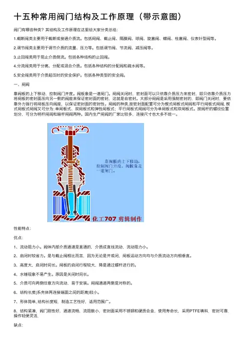
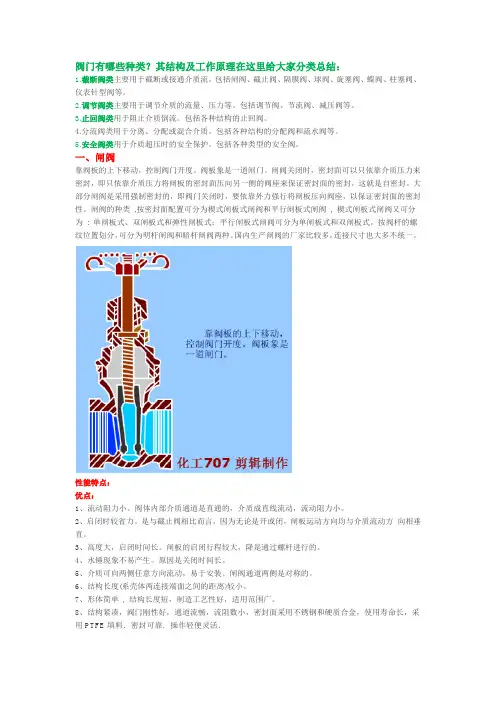
⼀、闸阀靠阀板的上下移动,控制阀门开度。
阀板象是⼀道闸门。
闸阀关闭时,密封⾯可以只依靠介质压⼒来密封,即只依靠介质压⼒将闸板的密封⾯压向另⼀侧的阀座来保证密封⾯的密封,这就是⾃密封。
⼤部分闸阀是采⽤强制密封的,即阀门关闭时,要依靠外⼒强⾏将闸板压向阀座,以保证密封⾯的密封性。
闸阀的种类,按密封⾯配置可分为楔式闸板式闸阀和平⾏闸板式闸阀, 楔式闸板式闸阀⼜可分为: 单闸板式、双闸板式和弹性闸板式;平⾏闸板式闸阀可分为单闸板式和双闸板式。
按阀杆的螺纹位置划分,可分为明杆闸阀和暗杆闸阀两种。
国内⽣产闸阀的⼚家⽐较多,连接尺⼨也⼤多不统⼀。
性能特点:优点:1、流动阻⼒⼩。
阀体内部介质通道是直通的,介质成直线流动,流动阻⼒⼩。
2、启闭时较省⼒。
是与截⽌阀相⽐⽽⾔,因为⽆论是开或闭,闸板运动⽅向均与介质流动⽅向相垂直。
3、⾼度⼤,启闭时间长。
闸板的启闭⾏程较⼤,降是通过螺杆进⾏的。
4、⽔锤现象不易产⽣。
原因是关闭时间长。
5、介质可向两侧任意⽅向流动,易于安装。
闸阀通道两侧是对称的。
6、结构长度(系壳体两连接端⾯之间的距离)较⼩。
7、形体简单, 结构长度短,制造⼯艺性好,适⽤范围⼴。
8、结构紧凑,阀门刚性好,通道流畅,流阻数⼩,密封⾯采⽤不锈钢和硬质合⾦,使⽤寿命长,采⽤PTFE填料.密封可靠.操作轻便灵活.缺点:密封⾯之间易引起冲蚀和擦伤,维修⽐较困难。
外形尺⼨较⼤,开启需要⼀定的空间,开闭时间长。
十五种常用阀门结构及工作原理(带示意图)阀门有哪些种类?其结构及工作原理在这里给大家分类总结:令狐采学1.截断阀类主要用于截断或接通介质流。
包括闸阀、截止阀、隔膜阀、球阀、旋塞阀、蝶阀、柱塞阀、仪表针型阀等。
2.调节阀类主要用于调节介质的流量、压力等。
包括调节阀、节流阀、减压阀等。
3.止回阀类用于阻止介质倒流。
包括各种结构的止回阀。
4.分流阀类用于分离、分配或混合介质。
包括各种结构的分配阀和疏水阀等。
5.安全阀类用于介质超压时的安全保护。
包括各种类型的安全阀。
一、闸阀靠阀板的上下移动,控制阀门开度。
阀板象是一道闸门。
闸阀关闭时,密封面可以只依靠介质压力来密封,即只依靠介质压力将闸板的密封面压向另一侧的阀座来保证密封面的密封,这就是自密封。
大部分闸阀是采用强制密封的,即阀门关闭时,要依靠外力强行将闸板压向阀座,以保证密封面的密封性。
闸阀的种类,按密封面配置可分为楔式闸板式闸阀和平行闸板式闸阀, 楔式闸板式闸阀又可分为: 单闸板式、双闸板式和弹性闸板式;平行闸板式闸阀可分为单闸板式和双闸板式。
按阀杆的螺纹位置划分,可分为明杆闸阀和暗杆闸阀两种。
国内生产闸阀的厂家比较多,连接尺寸也大多不统一。
性能特点:优点:1、流动阻力小。
阀体内部介质通道是直通的,介质成直线流动,流动阻力小。
2、启闭时较省力。
是与截止阀相比而言,因为无论是开或闭,闸板运动方向均与介质流动方向相垂直。
3、高度大,启闭时间长。
闸板的启闭行程较大,降是通过螺杆进行的。
4、水锤现象不易产生。
原因是关闭时间长。
5、介质可向两侧任意方向流动,易于安装。
闸阀通道两侧是对称的。
6、结构长度(系壳体两连接端面之间的距离)较小。
7、形体简单, 结构长度短,制造工艺性好,适用范围广。
8、结构紧凑,阀门刚性好,通道流畅,流阻数小,密封面采用不锈钢和硬质合金,使用寿命长,采用PTFE填料.密封可靠.操作轻便灵活.缺点:密封面之间易引起冲蚀和擦伤,维修比较困难。
阀门有哪些种类?其结构及工作原理在这里给大家分类总结:1.截断阀类主要用于截断或接通介质流。
包括闸阀、截止阀、隔膜阀、球阀、旋塞阀、蝶阀、柱塞阀、仪表针型阀等。
2.调节阀类主要用于调节介质的流量、压力等。
包括调节阀、节流阀、减压阀等。
3.止回阀类用于阻止介质倒流。
包括各种结构的止回阀。
4.分流阀类用于分离、分配或混合介质。
包括各种结构的分配阀和疏水阀等。
5.安全阀类用于介质超压时的安全保护。
包括各种类型的安全阀。
一、闸阀靠阀板的上下移动,控制阀门开度。
阀板象是一道闸门。
闸阀关闭时,密封面可以只依靠介质压力来密封,即只依靠介质压力将闸板的密封面压向另一侧的阀座来保证密封面的密封,这就是自密封。
大部分闸阀是采用强制密封的,即阀门关闭时,要依靠外力强行将闸板压向阀座,以保证密封面的密封性。
闸阀的种类,按密封面配置可分为楔式闸板式闸阀和平行闸板式闸阀, 楔式闸板式闸阀又可分为: 单闸板式、双闸板式和弹性闸板式;平行闸板式闸阀可分为单闸板式和双闸板式。
按阀杆的螺纹位置划分,可分为明杆闸阀和暗杆闸阀两种。
国内生产闸阀的厂家比较多,连接尺寸也大多不统一。
性能特点:优点:1、流动阻力小。
阀体内部介质通道是直通的,介质成直线流动,流动阻力小。
2、启闭时较省力。
是与截止阀相比而言,因为无论是开或闭,闸板运动方向均与介质流动方向相垂直。
3、高度大,启闭时间长。
闸板的启闭行程较大,降是通过螺杆进行的。
4、水锤现象不易产生。
原因是关闭时间长。
5、介质可向两侧任意方向流动,易于安装。
闸阀通道两侧是对称的。
6、结构长度(系壳体两连接端面之间的距离)较小。
7、形体简单, 结构长度短,制造工艺性好,适用范围广。
8、结构紧凑,阀门刚性好,通道流畅,流阻数小,密封面采用不锈钢和硬质合金,使用寿命长,采用PTFE填料.密封可靠.操作轻便灵活.缺点:密封面之间易引起冲蚀和擦伤,维修比较困难。
外形尺寸较大,开启需要一定的空间,开闭时间长。
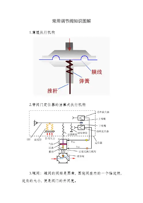
常用调节阀知识图解1.薄膜执行机构2.带阀门定位器的活塞式执行机构3.碟阀:蝶阀的阀瓣是圆盘, 围绕阀座内的一个轴旋转, 旋角的大小, 便是阀门的开闭度。
优点:轻巧、结构简单、比其他阀门要节省材料、开闭迅速,切断和节流都能用, 流体阻力小, 操作省力,可以做成很大口径。
应用:蝶阀在热水管路得到广泛的使用。
能够使用蝶阀的地方, 最好不要使用闸阀, 因为蝶阀比闸阀经济, 而且调节性好。
4.隔膜阀:隔膜阀是利用阀杆将弹性体薄膜紧压在阀座上用来隔断气路。
转动手轮可带动阀杆上、下移动,使隔膜离开阀座打开阀门或使隔膜紧压在阀座上关闭阀门。
应用场合:一是超纯水,超纯水要求流通管路内没有死角;二是有杂质的污水,溶液等,液体内有颗粒球阀容易磨损出现内漏,隔膜阀上下闭合极大的避免这个问题,长期使用后还可以更换隔膜片。
通常,使用条件或要求密封性能严格、泥浆介质、磨损、轻型结构、低压截止(压差小)、向大气少量渗漏、磨蚀性的介质时,推荐选用隔膜阀。
在双位调节、节流、调节、通道缩口、低噪声、有气穴和汽化现象、操纵转矩小的场合,可以选用隔膜阀。
在高温介质、高压介质、高压截止(压差大)、启闭动作快、结构长度短的条件下,不选用隔膜阀。
5.活塞执行机构6.角型阀角型阀:阀体为直角形,阀体内有一个阀座和密封面,一般为底进侧出。
优点:结构简单,密封效果好。
具有自洁净功能,阀体内不易存积污物,不宜堵塞,适用于控制高粘度介质,高压差以及含有悬浮物和颗粒物的介质。
缺点:容易发生阀芯振荡不稳定的现象。
7.气动薄膜调节阀:气动薄膜式执行机构有正作用和反作用。
正作用:当压力增大时,阀杆向下动作,压力是通入波纹膜片上方的薄膜气室。
反作用:当压力增大时,阀杆向上动作,压力是通入波纹膜片下方的薄膜气室。
8.气动活塞式执行机构9.三通阀阀体有三个接管口,适用于三个方向流体的管路控制系统,大多用于热交换器的温度调节、配比调节和旁路调节。
在使用中应注意流体温差不宜过大,通常小于是150℃,否则会使三通阀产生较大应力,否则会使三通阀产生较大应力而引起变形,造成连接处泄漏或损坏。
阀门有哪些种类?其结构及工作原理在这里给大家分类1.截断阀类主要用于截断或接通介质流。
包括闸阀、截止阀、隔膜阀、球阀、旋塞阀、蝶阀、柱塞阀、仪表针型阀等。
2.调节阀类主要用于调节介质的流量、压力等。
包括调节阀、节流阀、减压阀等。
3.止回阀类用于阻止介质倒流。
包括各种结构的止回阀。
4.分流阀类用于分离、分配或混合介质。
包括各种结构的分配阀和疏水阀等。
5.安全阀类用于介质超压时的安全保护。
包括各种类型的安全阀。
一、闸阀靠阀板的上下移动,控制阀门开度。
阀板象是一道闸门。
闸阀关闭时,密封面可以只依靠介质压力来密封,即只依靠介质压力将闸板的密封面压向另一侧的阀座来保证密封面的密封,这就是自密封。
大部分闸阀是采用强制密封的,即阀门关闭时,要依靠外力强行将闸板压向阀座,以保证密封面的密封性。
闸阀的种类 ,按密封面配置可分为楔式闸板式闸阀和平行闸板式闸阀 , 楔式闸板式闸阀又可分为 : 单闸板式、双闸板式和弹性闸板式;平行闸板式闸阀可分为单闸板式和双闸板式。
按阀杆的螺纹位置划分,可分为明杆闸阀和暗杆闸阀两种。
国内生产闸阀的厂家比较多,连接尺寸也大多不统一。
性能特点:优点:1、流动阻力小。
阀体内部介质通道是直通的,介质成直线流动,流动阻力小。
2、启闭时较省力。
是与截止阀相比而言,因为无论是开或闭,闸板运动方向均与介质流动方向相垂直。
3、高度大,启闭时间长。
闸板的启闭行程较大,降是通过螺杆进行的。
4、水锤现象不易产生。
原因是关闭时间长。
5、介质可向两侧任意方向流动,易于安装。
闸阀通道两侧是对称的。
6、结构长度(系壳体两连接端面之间的距离)较小。
7、形体简单 , 结构长度短,制造工艺性好,适用范围广。
8、结构紧凑,阀门刚性好,通道流畅,流阻数小,密封面采用不锈钢和硬质合金,使用寿命长,采用PTFE填料.密封可靠.操作轻便灵活.缺点:密封面之间易引起冲蚀和擦伤,维修比较困难。
外形尺寸较大,开启需要一定的空间,开闭时间长。
Accessory SchematicsThese drawings are helpful in determining what accessories are needed and their proper arrangement for a particular application. The following engineering schematics are used by Valtek when attaching accessories to control valves.Standard Positioner ControlAir FilterSchematic 19-1A:Positioner Signal-to-open, Fail-closedAir FilterSchematic 19-1B:Positioner Signal-to-close, Fail-open19-1119-12Supply EBP A BSupplyEB P AB Air FilterAir FilterSchematic 19-2B:Four-way Solenoid, De-energize-to-open, Fail-openSchematic 19-2A:Four-way Solenoid, De-energize-to-close, Fail-closedASCO 8345 - TypASCO 8345 - TypSolenoid Operated On-OffEAEA19-13Schematic 19-3A:Signal-to-open, Fail-closed, I/P 2000 SOV Signal Interrupt, De-energize-to-closeDe-energizing solenoid valve interrupts the signal to the positioner and drives the actuator to the low signalposition. This is dependent on the proper functioning of the positioner and the integrity of the feedback linkage.Schematic 19-3B:Signal-to-close, Fail-open, I/P 2000-SOV Signal Interrupt, De-energize-to-openSupplySupply19-14SupplySchematic 19-4A:Signal-to-open, Fail-closed, Three-way Solenoid Signal Interrupt, De-energize-to-closeASCO 8320 TYPSupplyDe-energizing solenoid valve interrupts the signal to the positioner and drives the actuator to the low signal posi-tion. This is dependent on the proper functioning of the positioner and the integrity of the feedback linkage.Schematic 19-4B:Signal-to-close, Fail-open, Three-way Solenoid Signal Interrupt, De-energize-to-open19-15Schematic 19-5A:Signal-to-open, Fail-closed, Three-way Solenoid Override, De-energize-to-closeSupplyAir FilterDe-energizing the solenoid blocks off the positioner output and vents the cylinder opposite the spring, allowing the spring to fail the valve.Soleniod must be rated for maximum supply pressure at all ports.Signal-to-close, Fail-open, Three-way Solenoid Override, De-energize-to-openSupply19-16Flow BoostersSupplySupplySchematic 19-6A:Signal-to-open, Fail-close, Flow BoostersSchematic 19-6B:Signal-to-close, Fail-open, Flow Boosters19-17Positioner with Quick ExhaustSchematic 19-7B:Signal-to-close, Fail-open, Quick Exhaust-to-openNeedle ValveSchematic 19-7A:Signal-to-open, Fail-closed, Quick Exhaust-to-closeAir FilterSupplyNeedle Valve19-18Schematic 19-8C:Signal-to-close, Fail-open, Speed Control in Open DirectionSupplyCheck ValveSupplyCheck ValveSupplyAir FilterSchematic 19-8A:Signal-to-open, Fail-closed, Speed Control in Both DirectionsSchematic 19-8B:Signal-to-open, Fail-closed, Speed Control in Closed DirectionSpeed Control SystemSupplyAir FilterSchematic 19-9A:Signal-to-open, Fail-in-placeLock-up SystemSchematic 19-9B:Signal-to-close, Fail-in-placeSupplyAir Filter19-1919-20Volume Tank Fail-Safe SystemSchematic 19-10B:Signal-to-close, Fail-open, Volume TankSupplySupplyAir FilterSchematic 19-10A:Signal-to-open, Fail-closed, Volume TankLock-up ValveSupplyVolume Tank Fail-Safe System with BoostersSupplySchematic 19-11B:Signal-to-close, Fail-open, Volume TankSchematic 19-11A:Signal-to-open, Fail-closed, Volume TankLock-up Valve(Normally Closed)Lock-up Valve(Normally Closed)19-2119-22Schematic 19-12B: Signal-to-close, Fail-openSchematic 19-12A:Signal-to-open, Fail-closedAir SupplyAir SupplyAir Spring System Using Cylinder VolumeOn-Off System with Quick ExhaustSchematic 19-13A:Fast-closing, Fail-closedSchematic 19-13B:Fast-opening, Fail-open19-23。
阀门有哪些种类?其结构及工作原理在这里给大家分类总结:1.截断阀类主要用于截断或接通介质流。
包括闸阀、截止阀、隔膜阀、球阀、旋塞阀、蝶阀、柱塞阀、仪表针型阀等。
2.调节阀类主要用于调节介质的流量、压力等。
包括调节阀、节流阀、减压阀等。
3.止回阀类用于阻止介质倒流。
包括各种结构的止回阀。
4.分流阀类用于分离、分配或混合介质。
包括各种结构的分配阀和疏水阀等。
5.安全阀类用于介质超压时的安全保护。
包括各种类型的安全阀。
一、闸阀靠阀板的上下移动,控制阀门开度。
阀板象是一道闸门。
闸阀关闭时,密封面可以只依靠介质压力来密封,即只依靠介质压力将闸板的密封面压向另一侧的阀座来保证密封面的密封,这就是自密封。
大部分闸阀是采用强制密封的,即阀门关闭时,要依靠外力强行将闸板压向阀座,以保证密封面的密封性。
闸阀的种类,按密封面配置可分为楔式闸板式闸阀和平行闸板式闸阀, 楔式闸板式闸阀又可分为: 单闸板式、双闸板式和弹性闸板式;平行闸板式闸阀可分为单闸板式和双闸板式。
按阀杆的螺纹位置划分,可分为明杆闸阀和暗杆闸阀两种。
国内生产闸阀的厂家比较多,连接尺寸也大多不统一。
性能特点:优点:1、流动阻力小。
阀体内部介质通道是直通的,介质成直线流动,流动阻力小。
2、启闭时较省力。
是与截止阀相比而言,因为无论是开或闭,闸板运动方向均与介质流动方向相垂直。
3、高度大,启闭时间长。
闸板的启闭行程较大,降是通过螺杆进行的。
4、水锤现象不易产生。
原因是关闭时间长。
5、介质可向两侧任意方向流动,易于安装。
闸阀通道两侧是对称的。
6、结构长度(系壳体两连接端面之间的距离)较小。
7、形体简单, 结构长度短,制造工艺性好,适用范围广。
8、结构紧凑,阀门刚性好,通道流畅,流阻数小,密封面采用不锈钢和硬质合金,使用寿命长,采用PTFE填料.密封可靠.操作轻便灵活.缺点:密封面之间易引起冲蚀和擦伤,维修比较困难。
外形尺寸较大,开启需要一定的空间,开闭时间长。
160研究与探索Research and Exploration ·工艺流程与应用中国设备工程 2021.01 (上)调节阀是自动调节系统不可缺少的组成部分,可以调节管路介质的压力、流量等。
调节阀按驱动能源形式分为气动、电动、液动三种。
气动调节阀是以压缩气为动力源,以气动薄膜或活塞气缸作为执行机构,借助阀门定位器、电磁阀等附件去控制,从而实现阀门的开关、比例式调节,并在整个气动调节阀气路控制原理分析魏高鹏(杭州杭氧工装泵阀有限公司,浙江 杭州 311305)摘要:调节阀是过程控制中一种重要的执行器,是自动调节系统不可缺少的组成部分,在实现工业生产自动化过程控制中有着重要地位。
不同阀门附件的组合使用可以提高调节阀的控制精度、速度、灵活性以及整个系统的安全性。
本文主要介绍定位器、电磁阀等附件的工作原理及功能,并分析几种典型的气路控制原理,作为自动化生产现场解决气动调节阀控制故障的参考资料。
关键词:调节阀;过程控制;附件;原理中图分类号:TF345 文献标识码:A 文章编号:1671-0711(2021)01(上)-0160-04控制系统出现电气故障或连锁时,使阀门回到安全位置。
1 气动调节阀主要附件的工作原理及功能1.1 电-气定位器定位器可以改善阀门的静态特性和动态特性,有助于克服介质对阀杆的不平衡力和填料对阀杆的摩擦力,提高控制本产品选用单晶硅太阳能电池作为电能转换装置。
④背板对电池片具有一定程度的保护作用,其具有防水、密封、耐老化的特点。
⑤铝合金保护层压件,起一定的密封、支撑作用。
⑥接线盒用于保护整个发电装置,接线盒会及时的自动断开短路电池串,防止烧坏整个装置。
⑦硅胶主要用来密封组件与铝合金边框、组件与接线盒交界处发电原理:光电效应,太阳光照射到电池的表面,电池片由于光生伏特效应将太阳光能直接转化成电能,产生电流,从而为软叶风扇以及照明灯供电。
其中,光生伏特效应是指半导体在受到光照射时产生电动势的现象。
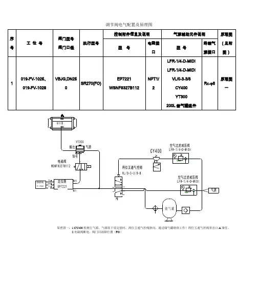
控制调节阀的标准气路图
1、用于开/关操作(单作用型:弹簧关)
气源切断时阀门关(当电磁阀得电时气源接通,阀门开)。
电磁阀失电时时阀门关(当电磁阀得电时气源接通,阀门开)。
下面是在电磁阀得电状态气路图
2、用于开/关操作(单作用型:弹簧开)
气源切断时阀门开(当电磁阀得电时气源接通,阀门关)。
电磁阀失电时时阀门开(当电磁阀得电时气源接通,阀门关)。
下面是在电磁阀得电状态气路图
3、用于调节——正作用(单作用型:弹簧开)
当信号增大时阀门关,当信号减小时阀门开
4、用于调节——反作用(单作用型:弹簧关)
当信号增大时阀门开,当信号减小时阀门关。
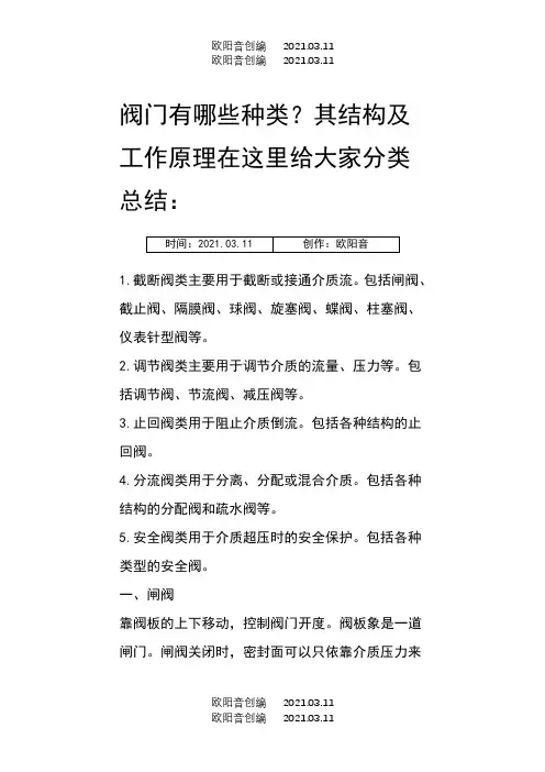
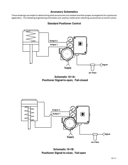
Accessory Schematics
These drawings are helpful in determining what accessories are needed and their proper arrangement for a particular application. The following engineering schematics are used by Valtek when attaching accessories to control valves.
Standard Positioner Control
Air Filter
Schematic 19-1A:
Positioner Signal-to-open, Fail-closed
Air Filter
Schematic 19-1B:
Positioner Signal-to-close, Fail-open
19-11
19-12
Supply EB
P A B
Supply
EB P A
B Air Filter
Air Filter
Schematic 19-2B:
Four-way Solenoid, De-energize-to-open, Fail-open
Schematic 19-2A:
Four-way Solenoid, De-energize-to-close, Fail-closed
ASCO 8345 - Typ
ASCO 8345 - Typ
Solenoid Operated On-Off
EA
EA
19-13
Schematic 19-3A:
Signal-to-open, Fail-closed, I/P 2000 SOV Signal Interrupt, De-energize-to-close
De-energizing solenoid valve interrupts the signal to the positioner and drives the actuator to the low signal
position. This is dependent on the proper functioning of the positioner and the integrity of the feedback linkage.
Schematic 19-3B:
Signal-to-close, Fail-open, I/P 2000-SOV Signal Interrupt, De-energize-to-open
Supply
Supply
19-14
Supply
Schematic 19-4A:
Signal-to-open, Fail-closed, Three-way Solenoid Signal Interrupt, De-energize-to-close
ASCO 8320 TYP
Supply
De-energizing solenoid valve interrupts the signal to the positioner and drives the actuator to the low signal posi-tion. This is dependent on the proper functioning of the positioner and the integrity of the feedback linkage.Schematic 19-4B:
Signal-to-close, Fail-open, Three-way Solenoid Signal Interrupt, De-energize-to-open
19-15
Schematic 19-5A:
Signal-to-open, Fail-closed, Three-way Solenoid Override, De-energize-to-close
Supply
Air Filter
De-energizing the solenoid blocks off the positioner output and vents the cylinder opposite the spring, allowing the spring to fail the valve.
Soleniod must be rated for maximum supply pressure at all ports.
Signal-to-close, Fail-open, Three-way Solenoid Override, De-energize-to-open
Supply
19-16
Flow Boosters
Supply
Supply
Schematic 19-6A:
Signal-to-open, Fail-close, Flow Boosters
Schematic 19-6B:
Signal-to-close, Fail-open, Flow Boosters
19-17
Positioner with Quick Exhaust
Schematic 19-7B:
Signal-to-close, Fail-open, Quick Exhaust-to-open
Needle Valve
Schematic 19-7A:
Signal-to-open, Fail-closed, Quick Exhaust-to-close
Air Filter
Supply
Needle Valve
19-18
Schematic 19-8C:
Signal-to-close, Fail-open, Speed Control in Open Direction
Supply
Check Valve
Supply
Check Valve
Supply
Air Filter
Schematic 19-8A:
Signal-to-open, Fail-closed, Speed Control in Both Directions
Schematic 19-8B:
Signal-to-open, Fail-closed, Speed Control in Closed Direction
Speed Control System
Supply
Air Filter
Schematic 19-9A:
Signal-to-open, Fail-in-place
Lock-up System
Schematic 19-9B:
Signal-to-close, Fail-in-place
Supply
Air Filter
19-19
19-20
Volume Tank Fail-Safe System
Schematic 19-10B:
Signal-to-close, Fail-open, Volume Tank
Supply
Supply
Air Filter
Schematic 19-10A:
Signal-to-open, Fail-closed, Volume Tank
Lock-up Valve
Supply
Volume Tank Fail-Safe System with Boosters
Supply
Schematic 19-11B:
Signal-to-close, Fail-open, Volume Tank
Schematic 19-11A:
Signal-to-open, Fail-closed, Volume Tank
Lock-up Valve
(Normally Closed)
Lock-up Valve
(Normally Closed)
19-21
19-22
Schematic 19-12B: Signal-to-close, Fail-open
Schematic 19-12A:
Signal-to-open, Fail-closed
Air Supply
Air Supply
Air Spring System Using Cylinder Volume
On-Off System with Quick Exhaust
Schematic 19-13A:
Fast-closing, Fail-closed
Schematic 19-13B:
Fast-opening, Fail-open
19-23。