霍尼韦尔CP-DIO
- 格式:pdf
- 大小:1.20 MB
- 文档页数:2

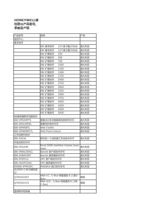
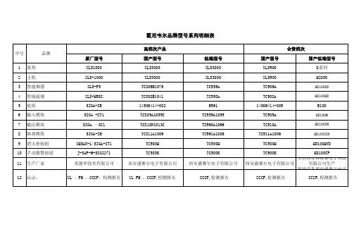
HONEYWELL楼控部分产品型号、参数及产地产品型号说明产地监控中心基本软件EBI 基本软件 12个读卡器/250点澳大利亚EBI 基本软件 12个读卡器/500点澳大利亚EBI 扩展软件 250澳大利亚EBI 扩展软件 500澳大利亚EBI 扩展软件 750澳大利亚EBI 扩展软件 1000澳大利亚EBI 扩展软件 1250澳大利亚EBI 扩展软件 1500澳大利亚EBI 扩展软件 1750澳大利亚EBI 扩展软件 2000澳大利亚EBI 扩展软件 2750澳大利亚EBI 扩展软件 3000澳大利亚EBI 扩展软件 3250澳大利亚EBI 扩展软件 3500澳大利亚EBI 扩展软件 3750澳大利亚EBI 扩展软件 4000澳大利亚EBI 扩展软件 4250澳大利亚EBI 扩展软件 4500澳大利亚EBI 扩展软件 5000澳大利亚BA服务器附件功能软件EBI-OPDASPTS数据点分布式数据库构架软件许可澳大利亚EBI-OPALMPAG报警传护软件许可澳大利亚EBI-OPWEBTL Web Toolkit澳大利亚EBI-OPWEBPCTL Web Point Control澳大利亚工作站附件软件EBI-XXCAL附件的一个浏览器工作站软件许可澳大利亚开放式软件许可EBI-IFXLDIR Excel 5000 interface license (scantask)澳大利亚EBI-IFBACDIRCL Bacnet 客户端软件许可澳大利亚EBI-SVBACNET Bacnet 服务器软件许可澳大利亚EBI-IFOPCCL OPC 客户端软件许可澳大利亚EBI-SVOPCDAS OPC 服务器软件许可澳大利亚SWEBI-IFMODIC MODBUS 接口软件许可澳大利亚XL5000 C-BUS通讯接口Q7055A1007BNA-1C,C-Bus-网络通讯卡 (1条C-Bus)德国Q7055A1015BNA-2CS,C-Bus-网络通讯卡 (2条C-Bus)德国直接数字控制器XL800控制器。
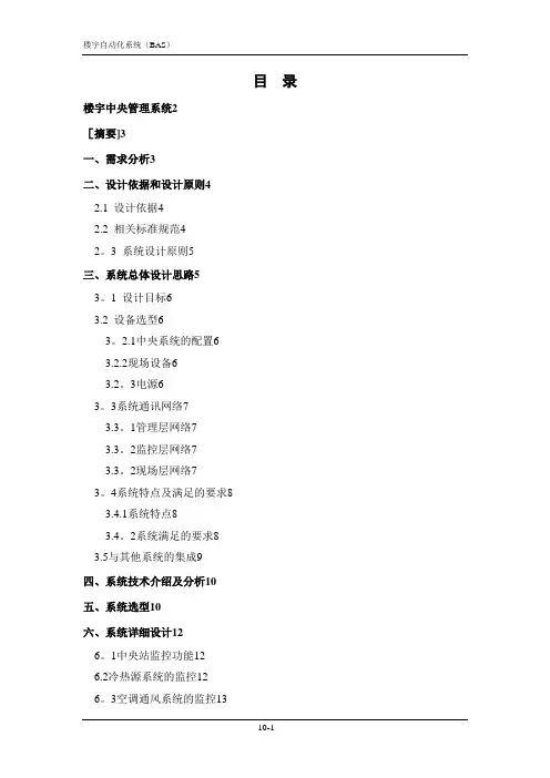
目录楼宇中央管理系统2[摘要]3一、需求分析3二、设计依据和设计原则42.1 设计依据42.2 相关标准规范42。
3 系统设计原则5三、系统总体设计思路53。
1 设计目标63.2 设备选型63。
2.1中央系统的配置63.2.2现场设备63.2。
3电源63。
3系统通讯网络73.3。
1管理层网络73.3。
2监控层网络73.3。
2现场层网络73。
4系统特点及满足的要求83.4.1系统特点83.4。
2系统满足的要求83.5与其他系统的集成9四、系统技术介绍及分析10五、系统选型10六、系统详细设计126。
1中央站监控功能126.2冷热源系统的监控126。
3空调通风系统的监控136.3.1空调系统146.4给排水系统的监控146。
4。
1给水系统146.4.2排水系统146.5电力系统的监测156。
5.1变配电系统156。
6其他系统15七、系统的扩容、扩建及故障影响16八、主要设备介绍168。
1 EBI系统168。
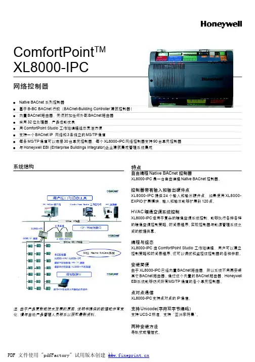
2 ComfortPoint BACnet控制系统178.3网络控制器CP—IPC198.4控制器扩展模块:CP—EXPIO228.4 现场控制器CP—SPC228。
5 ComfortPoint Open Studio编程工具介绍23九、系统使用功能介绍239.1中央站功能239。
1.1监视功能239.1.2 控制功能249.1。
3 先进的报警功能249。
1。
4 综合管理功能249.1。
5 通信及优化运行功能259.2 BACnet TCP/IP功能259.3 DDC功能269。
4 节能及能源控制软件29十、设备清单29楼宇自动化系统(BAS)方案[摘要]某项目BAS系统包括以下监控内容:冷源系统(包冷水机组、冷冻泵、冷却泵、冷却塔等)、空调机组、新风机组、排风机组、给排水系统(包括热泵机组、循环泵、生活水系统、污水处理系统等)、配电系统(包括低压配电、发电机等)、电梯系统等进行全自动监控,系统总监控点为:963点。

目录:非弹簧复位型风门驱动器 (2)非弹簧复位型风门驱动器(5/10NM) (2)非弹簧复位型风门驱动器(20NM/34NM) (4)弹簧复位型风门驱动器 (6)弹簧复位型风门驱动器(5/10/20NM) (6)非弹簧复位型风门驱动器非弹簧复位型风门驱动器5/10NM)应用CN系列风门执行器适用于电动风门控制,并可作为球阀的执行器,广泛应用于HVAC领域。
特点>自动调整轴杆中心位置>入口护套使连接更为方便>带手动离合按钮,可用于手动调节>机械末端限位>现场安装辅助开关>静音工作,一米处35dB>可预先接线>旋转方向可选>多种安装方向>机械位置指示>堵转扭矩过载保护>符合UL和CE认证技术规格>电压:24V/230V,50/60Hz (具体供电请参考附表)>工作温度:-20 (60)>相对湿度:5-・90%,不结霜>风门连杆:圆型连杆:8…16mm>方型连杆:6…13mm>连杆长度:最小41mm>防护等级:IP54>使用寿命:全程60,000次>重复定位:150万次>重量:450g选型说明非弹簧复位型风门驱动器20NM/34NM)应用CN系列风门执行器适用于电动风门控制,并可作为球阀的执行器,广泛应用于HVAC领域。
特点>自动调整轴杆中心位置>入口护套使连接更为方便>手动调节位置>机械末端限位>现场安装辅助开关>静音工作,一米处40dB>可预先接线>旋转方向可选>多种安装方向>机械位置指示技术规格>电压:24V/230V,50/60Hz (具体供电请参考附表)>工作温度:-20 (60)>相对湿度:5-・90%,不结霜>风门连杆:圆型连杆:10…27mm>方型连杆:10…18mm>连杆长度:最小22mm>防护等级:IP54>使用寿命:全程60,000次>重复定位:150万次>重量:1.4Kg选型说明弹簧复位型风门驱动器弹簧复位型风门驱动器5/10/20NM)应用CS系列风门执行器适用于电动风门控制,并可作为球阀的执行器,广泛应用于HVAC领域。

19 mm SeriesLow Cost, Stainless Steel, Isolated Pressure SensorsDESCRIPTIONHoneywell’s stainless steel 19C, 19U, and 19 Vacuum Gage Series sensors were developed for pressure applications that involve measurement of hostile media in harsh environments compatible with 316 stainless steel. The special Vacuum Gage Series sensors are specifically designed for applications that can be exposed to vacuum.The 19C Series are calibrated and temperature compensated. They are available for use with either a constant voltage or current source.They feature a variety of pressure connections to allow use in a wide range of OEM (Original Equipment Manufacturer) equipment. The 19U Series is uncompensated for applications that use their own specialized circuit designs.The 19C and 19U Series sensors are rugged and reliable transducers for use in a wide variety of pressure sensing applications where corrosive liquids or gases are monitored.FEATURES ∙ Low cost∙ Rugged, isolated stainless steel package ∙ Small size∙ Reliable semiconductor technology ∙ Calibrated and temperature compensated ∙ Absolute and gage pressures ∙ Vacuum compatible, isolated sensors ∙ 0 psi to 3 psi to, 0 psi to 500 psiPOTENTIAL APPLICATIONS ∙ Industrial controls ∙ Process control systems∙ Industrial automation and flow control ∙ Pressure calibrators19 mm SeriesPRESSURE SENSOR CHARACTERISTICS (All Devices)(1)2 /sensingLow Cost, Stainless Steel, Pressure Sensors(1)(1, 11)(1, 11)Honeywell Sensing and Control 319 mm SeriesNotes:1.Reference conditions (unless otherwise noted): TA = 25 °C [77 °F]; 19C Supply VS = 10 Vdc ±0.01 Vdc orIS = 1.5 mA ±0.0015 mA; 19U Supply VS = 5 Vdc ±0.01 Vdc or I = 1.0 mA ±0.0015 mA.2.Full-scale span (FSS) is the algebraic difference between the output voltage at full-scale pressure and the output at zeropressure. FSS is ratiometric to supply voltage.3.Pressure non-linearity is based on best-fit straight line from zero to the full-scale pressure. Pressure hysteresis is themaximum output difference at any point within the operation pressure range for increasing and decreasing pressure.4.Maximum error band of the offset voltage or span over the compensated temperature range, relative to the 25 °C [77 °F]reading.5.Long-term stability over a six-month period.6.Response time for a 0 psi to FSS pressure step change, 10% to 90% rise time.7.The maximum pressure that can be applied without chan ging the transducer’s performance or accuracy.8.The maximum pressure that can be applied to a transducer without rupture of either the sensing element or transducermon mode voltage as measured from output to ground. For higher levels of common mode voltage, contact factory.10.The error band resulting from a maximum deviation of a transducer’s output parameter (offset, span, or resistance) astemperature is varied 25 °C [77 °F] to any other temperature within the specified range (0 °C to 82 °C [32 °F to 180 °F]). This parameter is not 100% tested and is guaranteed by process design and tested on a sample basis only. Temperaturecoefficient of span is evaluated using a 1 mA constant current excitation source.11.Vacuum gage products may be affected by changes in environmental humidity levels. The specifications shown exclude theseeffects.PHYSICAL DIMENSIONS (For reference only: mm [in].)Note: Non-concentricity effects at the diaphragm weld area may cause runout of up to ±0.006 in between the upper and lower portions of the sensor body. (It is recommended to use a counter bore to mate with this device to allow for this non-concentricity).4 Honeywell Sensing and ControlLow Cost, Stainless Steel, Pressure SensorsHoneywell Sensing and Control 519 mm Seriesportions of the sensor body. (It is recommended to use a counter bore to mate with this device to allow for this non-concentricity).6 Honeywell Sensing and ControlLow Cost, Stainless Steel, Pressure SensorsORDERING INFORMATIONHoneywell Sensing and Control 7Sensing and Control Honeywell1985 Douglas Drive NorthMinneapolis, MN 55422 /sensing 009132-4-EN IL50 GLO Printed in USAFebruary 2020Copyright © 2020 Honeywell International Inc. All rights reserved.PERSONAL INJURYWARRANTY/REMEDYHoneywell warrants goods of its manufacture as being free of defective materials and faulty workmanship. Honeywell’s standard product warranty applies unless agreed to otherwise by Honeywell in writing; please refer to your order acknowledgement or consult your local sales office for specific warranty details. If warranted goods are returned to Honeywell during the period of coverage, Honeywell will repair or replace, at its option, without charge those items it finds defective. The foregoing is b uyer’s sole remedy and is in lieu of all other warranties, expressed or implied, including those of merchantability and fitness for a particular purpose. In no event shall Honeywell be liable for consequential, special, or indirect damages.While we provide application assistance personally, through our literature and the Honeywell web site, it is up to the customer to determine the suitability of the product in the application.Specifications may change without notice. The information we supply is believed to be accurate and reliable as of this printing. However, we assume no responsibility for its use.MISUSE OF DOCUMENTATIONSALES AND SERVICEHoneywell serves its customers through a worldwide network of sales offices, representatives and distributors. For application assistance, current specifications, pricing or name of the nearest Authorized Distributor, contact your local sales office or:Phone:Asia Pacific: +65 6355-2828Europe: +44 1698 481481USA/Canada: +1-302-613-4491。
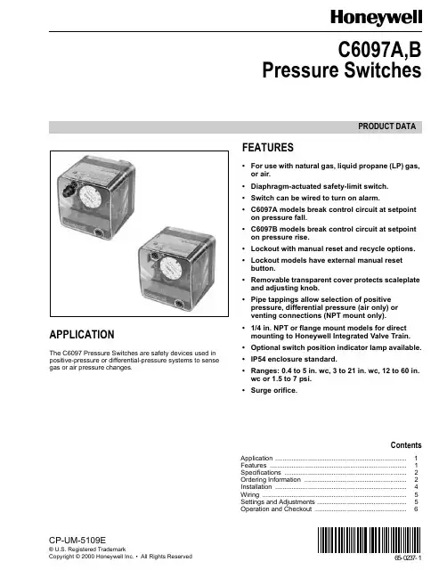
PRODUCT DATA65-0237-1CP-UM-5109E® U.S. Registered TrademarkCopyright © 2000 Honeywell Inc. • All Rights ReservedC6097A,BPressure SwitchesAPPLICATIONThe C6097 Pressure Switches are safety devices used in positive-pressure or differential-pressure systems to sense gas or air pressure changes.FEATURES•For use with natural gas, liquid propane (LP) gas, or air.•Diaphragm-actuated safety-limit switch.•Switch can be wired to turn on alarm.•C6097A models break control circuit at setpoint on pressure fall.•C6097B models break control circuit at setpoint on pressure rise.•Lockout with manual reset and recycle options.•Lockout models have external manual reset button.•Removable transparent cover protects scaleplate and adjusting knob.•Pipe tappings allow selection of positive pressure, differential pressure (air only) or venting connections (NPT mount only).•1/4 in. NPT or flange mount models for direct mounting to Honeywell Integrated Valve Train.•Optional switch position indicator lamp available.•IP54 enclosure standard.•Ranges: 0.4 to 5 in. wc, 3 to 21 in. wc, 12 to 60 in. wc or 1.5 to 7 psi.•Surge orifice.ContentsApplication ........................................................................1Features ...........................................................................1Specifications ...................................................................2Ordering Information ........................................................2Installation ........................................................................4Wiring ...............................................................................5Settings and Adjustments .................................................5Operation and Checkout ..................................................6C6097A,B PRESSURE SWITCHES65-0237—12ORDERING INFORMATIONWhen purchasing replacement and modernization products from your TRADELINE® wholesaler or distributor, refer to theTRADELINE® Catalog or price sheets for complete ordering number.If you have additional questions, need further information, or would like to comment on our products or services, please write or phone:1.Your local Home and Building Control Sales Office (check white pages of your phone directory).2.Home and Building Control Customer Logistics Honeywell Inc., 1885 Douglas Drive NorthMinneapolis, Minnesota 55422-4386 (612) 951-1000In Canada—Honeywell Limited/Honeywell Limitée, 155 Gordon Baker Road, North York, Ontario M2H 3N7.International Sales and Service Offices in all principal cities of the world. Manufacturing in Australia, Canada, Finland, France, Germany, Japan, Mexico, Netherlands, Spain, Taiwan, United Kingdom, U.S.A.SPECIFICATIONSModels:C6097A Pressure Switch: Breaks a circuit when pressure falls to scale setting. See Table 1.C6097B Pressure Switch: Breaks a circuit when pressure rises to scale setting. See Table 1.Table 2 shows switch ratings and Table 3 shows alternate electrical ratings when used with Honeywell Flame Safeguard Programmers.Minimum Ambient Temperature: -40°F (-40°C).Maximum Ambient Temperature: 140°F (60°C).Connections (Depending on Model):1/4-18 NPT tapping for main or high-pressure connection.1/8-27 NPT tapping for vent or low-pressure connection (air only).Flange mount for connection to Honeywell Integrated Valve Train (internal vent only, no external connections).Scale Range:0.4 to 5 in. wc (0.10 kPa to 1.25 kPa).3 to 21 in. wc (0.75 to 5.23 kPa).12 to 60 in. wc (3.0 kPa to 15 kPa).1.5 to 7 psi (10.3 kPa to 48 kPa).Approvals:Underwriters Laboratories Inc. listed.Canadian Standards Association listed.Factory Mutual: Approved.Industrial Risk Insurers: Acceptable.CSD-1 AFB: Acceptable.Accessories:32003041-001 C6097 Cover for manual reset models.32003040-001 C6097 Cover for recycle models.32003039-001 Position Indication Lamp Kit.Dimensions: See Fig. 1 and 2.Fig. 1. C6097 1/4 in. NPT Mount dimensions in in. (mm).C6097A,B PRESSURE SWITCHES365-0237—1a Acceptable media: Natural gas, liquid propane (LP) gas, and air .Table 1. Pressure Switch Model Selection.Model Operating Pressure Range Manual Reset DifferentialNon-Manual ResetDifferentialDifferential Type Maximum Rated Pressure(continuous) (psi)Manual Reset Media a Switch Action at Setpoint Comments Maximumat Minimum Setpoint Maximumat MaximumSetpoint Nominal Maximum C6097A10040.4 to 5 in. wc——0.16 in. wc 0.24 in. wc Additive2.9 No Air/Gas Breaks N.O. to C.connection on pressure fall.1/4 in. NPT Mount C6097A1012 3 to 21 in. wc2.4 in. wc 4.2 in. wc —— 4.3Yes Air/Gas 1/4 in. NPT Mount C6097A1020 3 to 21 in. wc 2.4 in. wc 4.2 in. wc —— 4.3Yes Air/Gas Flange Mount C6097A103812 to 60 in. wc 10 in. wc 12 in. wc —— 4.8Yes Air/Gas 1/4 in. NPT Mount C6097A104612 to 60 in. wc10 in. wc12 in. wc—— 4.8Yes Air/Gas Flange Mount C6097A1053 3 to 21 in. wc—0.24 in. wc0.48 in. wc 4.3No Air/Gas 1/4 in. NPT Mount C6097A1061 3 to 21 in. wc ——0.24 in. wc0.48 in. wc4.3No Air/Gas Flange Mount C6097A107912 to 60 in. wc —— 1.1 in. wc 2.4 in. wc 4.8No Air/Gas 1/4 in. NPT Mount C6097A108712 to 60 in. wc—— 1.1 in. wc 2.4 in. wc 4.8No Air/Gas Flange Mount C6097A10950.4 to 5 in. wc 0.6 in. wc 1.0 in. wc —— 2.9Yes Air/Gas 1/4 in. NPT Mount C6097A1103 1.5 to 7 psi 1.1 psi 1.4 psi ——9.3Yes Air/Gas Flange Mount C6097A1111 1.5 to 7 psi 1.1 psi 1.4 psi ——9.3Yes Air/Gas 14 in. NPT Mount C6097A1129 1.5 to 7 psi ——0.1 psi 0.39.3No Air/Gas Flange Mount C6097A1137 1.5 to 7 psi——0.1 psi 0.39.3No Air/Gas 1/4 in. NPT Mount C6097A12100.4 to 5 in. wc——0.16 in. wc 0.24 in. wc 2.9No Air/Gas Flange Mount C6097A12280.4 to 5 in. wc ———— 2.9Yes Air/Gas Flange MountC6097B100212 to 60 in. wc 10 in. wc 12 in. wc ——Subtractive4.8Yes Air/Gas Breaks N.C. to C. connectionon pressure rise.1/4 in. NPT Mount C6097B101012 to 60 in. wc10 in. wc12 in. wc —— 4.8Yes Air/Gas Flange Mount C6097B1028 3 to 21 in. wc2.4 in. wc 4.2 in. wc —— 4.3Yes Air/Gas 1/4 in. NPT MountC6097B1036 3 to 21 in. wc 2.4 in. wc 4.2 in. wc —— 4.3Yes Air/Gas Flange Mount C6097B1044 1.5 to 7 psi 1.1 psi 1.4 psi ——21.0Yes Air/Gas Flange Mount C6097B1051 1.5 to 7 psi1.1 psi1.4 psi ——21.0Yes Air/Gas 1/4 in. NPT Mount C6097B1069 3 to 21 in. wc ——0.24 in. wc0.48 in. wc4.3No Air/Gas Flange Mount C6097B107712 to 60 in. wc —— 1.1 in. wc 2.4 in. wc 4.8No Air/Gas Flange Mount C6097B108512 to 60 in. wc —— 1.1 in. wc 2.4 in. wc 4.8No Air/Gas 1/4 in. NPT Mount C6097B1093 1.5 to 7 psi ——0.1 psi 0.3 psi 21.0No Air/Gas Flange Mount C6097B1101 1.5 to 7 psi——0.1 psi 0.3 psi 21.0No Air/Gas 1/4 in. NPT Mount C6097B11193 to 21 in. wc——0.24 in. wc0.48 in. wc4.3NoAir/Gas1/4 in. NPT MountC6097A,B PRESSURE SWITCHES65-0237—14Table 2. Switch Ratings (Amperes)Table 3. Alternate Electrical Ratings when used withHoneywell Flame Safeguard Programmers.Fig. 2. C6097 Flange Mount dimensions in in. (mm).INSTALLATIONWARNINGExplosion or Fire Hazard.Can cause severe personal injury, death or property damage.Observe all safety requirements each time a control is installed on a burner.When Installing this Product...1.Read these instructions carefully. Failure to follow them can damage the product or cause a hazardous condition.2.Check the ratings given in the instructions and on the product to make sure that the product is suitable for your application.3.Installer must be a trained, experienced service technician.4.After installation is completed, check out product operation as provided in these instructions.WARNINGElectrical Shock Hazard.Can cause serious personal injury or death.Disconnect power supply before beginning installation. More than one disconnection can be involved.MountingNOTE:On flange models, remove the label holding theO-ring in place and make sure O-ring seal is in place before mounting the pressure switch on the valve.The C6097 models allow NPT or flange (directly to valve) mounting. The NPT models have a hexagonal fitting with a 1/4 in. NPT tapping, which is the high pressure connection, in differential applications. The bleed fitting is 1/8 in. NPTtapped. In differential pressure control applications using air only, connect the lower pressure to the bleed fitting. See Fig. 1 and Table 1. In applications using combustible gases, vent the bleed tapping according to applicable standard code or jurisdictional authority.C6097 models with flange mount can be fitted directly toHoneywell Integrated Valve Train (model specific). See Fig. 2 and Table 1. The flange mount models vent internally, with no external tap.Mount the C6097A,B in any position.Leak CheckAfter installation, perform a leak check on the pressure switch:1.Turn on main gas. Make sure gas has reached thepressure switch (e.g., high gas pressure switch)2.Check installation for gas leaks using a gas leak detector or a soap solution.120/240 Vac, 50/60 HzInductive Full Load 3.0Locked Rotor18.0Resistive5.0DeviceRatingIgnition Transformer 540 VA Pilot Valve 50 VAMain Valve400 VA with 2-1/2 times inrush.C6097A,B PRESSURE SWITCHES565-0237—1WIRINGWARNINGElectrical Shock Hazard.Can cause serious personal injury or death.Disconnect power supply before beginning installation. More than one disconnection can be involved.Make sure that all wiring agrees with all applicable localcodes, ordinances and regulations. An opening is provided to accommodate rigid conduit or armored cable for line voltage operation (see Fig. 3 and 4). Do not overload the switch contacts (see Switch Ratings in the Specifications section). The switching schematic is shown in Fig. 5.Fig. 3. C6097 (manual reset switch model)with cover removed.Fig. 4. C6097 (recycle model) with cover removed.SETTINGS AND ADJUSTMENTSPressure Setpoint Adjustmentdial (Fig. 3, 4 and 5) clockwiseto decrease the pressure setting.Fig. 5. C6097 schematic.C6097A,B PRESSURE SWITCHES65-0237—16OPERATION AND CHECKOUTOperationThe manual reset C6097A diaphragm actuates the snap-acting switch to break a control circuit and lock out when pressure falls to the scale setting. The recycle C6097Amodels recycle automatically when the control circuit returns to scale setting plus differential.The manual reset C6097B diaphragm actuates the snap-acting switch that breaks a control circuit and locks out when the pressure rises to the scale setting. The recycle C6097B models recycle automatically when the control pressure falls to the scale setting minus differential.Manual ResettingThe C6097A manual reset models lock out when pressure falls to the scale setting and require manual resetting after the pressure rises to scale setting plus differential to resume normal operation.The C6097B manual reset models lock out when pressure rises to the scale setting and require manual resetting after the pressure falls to scale setting minus the differential to resume normal operation.To reset, once normal operating pressure is restored, push the reset button in as far as it goes, then release.IMPORTANTLockout models cannot be made to recycleautomatically by permanently holding in the reset lever.CheckoutC6097 Gas Fuel Application1.Set cutoff pressure.2.Open main supply line. Depress reset lever on lockout models until switch makes control circuit.3.Set controller and limit switch to call for heat.4.For C6097A: Close the manual gas shutoff valve. C6097 should open control circuit when pressure reaches cutoff point.For C6097B: Open the manual gas shutoff valve, wait a few minutes for the pressure to rise; then lower the scale setting until the switch breaks control circuit and locks out.5.For C6097A: Open the shutoff valve, return thepressure switch to its original setting and press the reset button (if necessary).For C6097B: raise setting to normal and press reset button (if necessary).6.Allow system to operate through at least one complete cycle to make sure all components are functioning properly.C6097A Air Application1.Set cutoff pressure.2.Turn on fan.3.Block fan inlet or filter area. Switch should break control circuit when pressure drops to cutoff point. Manual reset models lock out.4.Remove obstruction. Press reset lever (manual reset models) and allow system to operate through at least one complete cycle to be sure all components are functioning properly.765-0237—165-0237—1 G.R. Rev. 4-00Home and Building Control Home and Building ControlHoneywell Asia Pacific Inc.Honeywell Inc.Honeywell Limited-Honeywell Limitée Room 3213-3225Honeywell Plaza 155 Gordon Baker Road Sun Hung Kai Centre P.O. Box 524North York, Ontario No. 30 Harbour Road Minneapolis, MN 55408-0524M2H 3N7Wanchai Hong KongHoneywell Latin American Region Honeywell Europe S.A.480 Sawgrass Corporate Parkway 3 Avenue du Bourget Suite 2001140 Brussels Sunrise FL 33325Belgium。

2017-HBS-0528-CN© 2017霍尼韦尔国际有限公司HBS 官方微信网址: 邮件: hbschina@ 维保服务热线: 400 920 2288霍尼韦尔智能建筑与家居集团建筑智能系统部中国上海浦东新区张江高科技园区环科路555号1号楼电话: (86-21) 8038 8600传真: (86-21) 6024 6073邮编: 201203北京办事处北京市朝阳区酒仙桥路14号兆维工业园甲一号楼5层电话: (86-10) 5669 6000传真: (86-10) 5756 0509邮编: 100015天津办事处天津市河西区解放路256号泰达大厦17层A2电话: (86-22) 5881 6607传真: (86-22) 5881 6643邮编: 300042广州办事处广州市海珠区滨江中路308号海运大厦15楼A 座电话: (86-20) 8410 1800传真: (86-20) 8410 1816邮编: 510220深圳办事处深圳市南山区东滨路4078号永新汇1号楼17、18楼电话: (86-755) 3638 1700传真: (86-755) 2518 1220邮编: 518054香港办事处香港北角英皇道255号国都广场霍尼韦尔大厦21楼电话: (852) 2331 9133传真: (852) 2953 6772澳门办事处澳门新口岸宋玉生广场249-263号中土大厦16楼F 座电话: (853) 2875-7580台湾办事处台湾新北市中和区连城路168号10楼电话: (886) 2 2245 1000传真: (886) 2 2245 3242HBS 官方微博易于集成• ComfortPoint Open 楼宇管理系统支持本地BACnet ®通信协议,能够连接其它支持BACnet ®协议的服务器或设备并与之实现交互操作。
提高用户生产效率,降低运营成本• ComfortPoint Open 配备专门设计用于移动系统访问的霍尼韦尔EasyMobile 客户端。
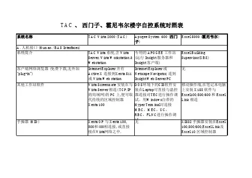
TAC 、西门子、霍尼韦尔楼宇自控系统对照表
TAC 、西门子、霍尼韦尔楼宇自控系统对照表
TAC 、西门子、霍尼韦尔楼宇自控系统对照表
TAC 、西门子、霍尼韦尔楼宇自控系统对照表
TAC 、西门子、霍尼韦尔楼宇自控系统对照表
TAC 、西门子、霍尼韦尔楼宇自控系统对照表
TAC 、西门子、霍尼韦尔楼宇自控系统对照表
TAC 、西门子、霍尼韦尔楼宇自控系统对照表
TAC 、西门子、霍尼韦尔楼宇自控系统对照表
TAC 、西门子、霍尼韦尔楼宇自控系统对照表
TAC 、西门子、霍尼韦尔楼宇自控系统对照表
TAC 、西门子、霍尼韦尔楼宇自控系统对照表
TAC 、西门子、霍尼韦尔楼宇自控系统对照表
TAC 、西门子、霍尼韦尔楼宇自控系统对照表
TAC 、西门子、霍尼韦尔楼宇自控系统对照表。
· ScanPal TM Enterprise Hybrid Device ;· Main battery (3.8V, lithium ion battery);· Regulator sheet.Remarks:If you ordered accessories for the terminal, please make sure they are also included in the package; be sure to keep the original packages for TM ScanPal EDA 70 to be returned for repairing when necessary.Note:End users should not arbitrarily replace the operating system with other operating systems. To update operating system installed on your device, you need to get license from the OS vendors.TM EDA 70-0/EDA 70-3 belongs to ScanPal SeriesRight Side View Install the Main BatteryReplace the battery with wrong models may cause explosion. Please make sure to use the battery in accordance with local regulations.Please recycle the battery when possible.Do not dispose it as household wastePlease ensure all kits are dry when connect the mobile device or battery to external devices.Damages caused by connecting wet kits are not covered by the warranty.1. Press down the battery cover safety button to move the battery cover safety lock to the unlock position at right;2. Open the battery cover with the battery cover buckle handle ;3. Insert the battery (Insert the non-connector side first, then press the battery down to establish connection between the battery and the phone)4. Press down the battery cover (Insert the non-connector side first, then press the battery cover down)5. Press down the battery cover safety button to move the battery cover safety lock to the lock position at leftRemarks:Refer to the illustrated installation steps on the following page.ScanPal TM EDA 70 comes with a battery in a separate package. Please follow the steps below to install the battery.Suspend / Wake Up the TerminalSuspend / Wake Up the TerminalPress the power button and then release (less than 2 seconds)To wake up the device from sleep mode, press the power button and then release (less than 2 seconds)TMScanPal EDA 70 Power IndicatorThe status of power indicators in non-charging and charging processare illustrated as below:Non- charging processOffBattery power is normal Flashing orange Battery power is low Charging process Constant green Charging complete Flashing green During charging process, and the charging is about to be completedOrangeDuring charging process, and the battery power is still low Flashing redBattery is abnormalTechnical SupportFor information about technical support, after-sales service and maintenance, please visit .User DocumentsFor the local version of this article, please visit .PatentsFor information on patents, please refer to /patents.WarrantyPlease log into /warranty_information for warranty information on your product.DisclaimerHoneywell International Inc. reserves the rights to modify the specifications and other information mentioned above without prior notification.Readers should consult Honeywell International Inc. to make sure if any changes made any time they read this article.The information in this article does not represent any commitments of Honeywell International Inc.Honeywell International Inc. is not responsible for direct or indirect loss caused by any technical or editing errors or omissions contained in this article.The proprietary information contained in this article is protected by copyright.All rights reserved.Without prior written consent from Honeywell International Inc., any form of photocopy, copy or translation into other languages for any part of this article is not allowed.All Rights Reserved by Honeywell International Inc.Website: 。
honeywell clip xt使用手册概述及解释说明1. 引言1.1 概述本使用手册旨在为用户提供关于Honeywell Clip XT的详细信息和操作指南。
作为一款先进的便携式气体检测仪器,Honeywell Clip XT具有出色的性能和可靠的功能,广泛应用于各行各业,特别是在工业领域中的危险场所。
1.2 文章结构本文将按照以下结构展开介绍和解释说明:- 第2部分:Honeywell Clip XT 使用手册概述,包括产品介绍、功能特点以及使用范围。
- 第3部分:解释说明,主要包括安装指南、操作步骤以及故障排除与常见问题解答。
- 第4部分:结论,总结回顾Honeywell Clip XT的主要特点和功能,并提供使用建议和展望未来发展趋势。
通过这样的章节划分,读者可以逐步了解Honeywell Clip XT相关内容,并掌握正确的使用方法和技巧。
1.3 目的撰写本篇文章的目的是帮助使用者深入了解Honeywell Clip XT,并为其提供详细而准确的操作指南。
我们希望通过这篇文章,读者能够充分认识到Honeywell Clip XT在危险环境监测方面的重要性和价值,并能够正确、安全地操作该设备。
通过阅读本文章,读者将了解到Honeywell Clip XT的产品特点、适用范围以及使用方法。
同时,我们也将提供一些故障排除和常见问题解答,以帮助用户在面临困扰时能够快速解决问题。
总之,本手册的目标是为用户提供全面而详尽的关于Honeywell Clip XT 的信息和指南,使他们能够更好地理解和应用这一先进的气体检测仪器。
2. Honeywell Clip XT 使用手册概述2.1 产品介绍Honeywell Clip XT是一款便携式气体检测仪器,具有高精度和灵敏度。
它使用最先进的传感技术,能够准确检测并监测任何危险气体的存在。
该仪器广泛应用于消防、工业、矿山和化工等领域,为工作场所和人员安全提供了可靠保障。