优解ZL2200激光扫描枪
- 格式:ppt
- 大小:486.00 KB
- 文档页数:7

脉冲光纤激光器使用说明书RFL-P20/30QS+武汉锐科光纤激光技术股份有限公司Wuhan Raycus Fiber Laser Technologies CO., LTD.安全信息在使用该产品之前,请先阅读和了解这份用户手册并熟悉我们为您提供的信息。
这份用户手册提供了重要的产品操作,安全以及其他信息给您以及所有将来的用户作参考。
为了确保操作安全和产品的最佳性能,请遵循以下注意和警告事项以及该手册的其他信息去操作。
a)锐科公司脉冲光纤激光器是IV级的激光产品。
在打开24VDC电源前,要确保连接是正确的24VDC的电源并确认正负极,错误连接电源,将会损坏激光器。
b)该激光器在1060~1085nm波长范围内发出超过20,30 W的激光辐射。
避免眼睛和皮肤接触到光输出端直接发出或散射出来的辐射。
c)不要打开机器,因为没有可供用户使用的产品零件或配件。
所有保养或维修只能在锐科公司内进行。
d)不要直接观看输出头,在操作该机器时要确保长期配戴激光安全眼镜。
安全标识及位置上面二个安全标识符号表示有激光辐射,我们把这符号标在产品光纤盒体盖顶上。
目录1.产品描述 (1)1.1.产品描述 (1)1.2.实际配置清单 (1)1.3.使用环境要求及注意事项 (1)1.4.技术参数 (2)2. 安装 (3)2.1. 安装尺寸图 (3)2.2. 安装方法 (4)3. 控制接口 (5)4. 操作程序 (7)4.1. 前期检查工作 (7)4.2. 操作步骤 (7)4.3. 打标过程中应注意的事项 (7)5. 质保及返修、退货流程 (7)5.1. 一般保修 (7)5.2. 保修的限定性 (7)5.3. 服务和维修 (8)1.产品描述1.1.产品描述锐科脉冲激光器是为高速和高效的激光打标系统而专门发展的,为工业激光打标机和其它应用提供了一款理想的高功率激光能量源。
脉冲激光器相对于传统的激光器,能够对每瓦的泵浦光转换效率提高10倍以上,低能量消耗的自动设计,适合实验室或室外操作。

Printed in U.S.A.TABLE OF CONTENTSPageSPECIFICATIONS . . . . . . . . . . . . . . . . . . . . . . . . . . . . . . . . . . . . . . . . . . . . . . 1INTRODUCTION . . . . . . . . . . . . . . . . . . . . . . . . . . . . . . . . . . . . . . . . . . . . . . . 1CONNECTOR CHART . . . . . . . . . . . . . . . . . . . . . . . . . . . . . . . . . . . . . . . . . . . . 1MEMORY MAP . . . . . . . . . . . . . . . . . . . . . . . . . . . . . . . . . . . . . . . . . . . . . . . . 1CIRCUIT ANALYSIS . . . . . . . . . . . . . . . . . . . . . . . . . . . . . . . . . . . . . . . . . . . . . 1BLOCK DIAGRAM . . . . . . . . . . . . . . . . . . . . . . . . . . . . . . . . . . . . . . . . . . . . 1DS2250 MICROPROCESSOR . . . . . . . . . . . . . . . . . . . . . . . . . . . . . . . . . . . . . . 1DUAL PORT RAM . . . . . . . . . . . . . . . . . . . . . . . . . . . . . . . . . . . . . . . . . . . . 1ON BOARD RAM U12 AND U13 . . . . . . . . . . . . . . . . . . . . . . . . . . . . . . . . . . . . 2OSCILLATOR . . . . . . . . . . . . . . . . . . . . . . . . . . . . . . . . . . . . . . . . . . . . . . . 2RESET . . . . . . . . . . . . . . . . . . . . . . . . . . . . . . . . . . . . . . . . . . . . . . . . . . . 2LOAD/RUN . . . . . . . . . . . . . . . . . . . . . . . . . . . . . . . . . . . . . . . . . . . . . . . . 2RS-232 INTERFACE . . . . . . . . . . . . . . . . . . . . . . . . . . . . . . . . . . . . . . . . . . . 2BIT I/O . . . . . . . . . . . . . . . . . . . . . . . . . . . . . . . . . . . . . . . . . . . . . . . . . . . 2LED INDICATORS . . . . . . . . . . . . . . . . . . . . . . . . . . . . . . . . . . . . . . . . . . . . 3TROUBLESHOOTING . . . . . . . . . . . . . . . . . . . . . . . . . . . . . . . . . . . . . . . . . . . . 3PROGRAMMING INSTRUCTIONSLOADING 344A4414G1 SOFTWARE INTO THE GETC 1e MODULE . . . . . . . . . . . . . . . . . 3REQUIRED ITEMS . . . . . . . . . . . . . . . . . . . . . . . . . . . . . . . . . . . . . . . . . . . . 3PREPARATION . . . . . . . . . . . . . . . . . . . . . . . . . . . . . . . . . . . . . . . . . . . . . . 3LOADING PROCEDURE . . . . . . . . . . . . . . . . . . . . . . . . . . . . . . . . . . . . . . . . 3ERRORS . . . . . . . . . . . . . . . . . . . . . . . . . . . . . . . . . . . . . . . . . . . . . . . . . . 3SERIAL NUMBERING . . . . . . . . . . . . . . . . . . . . . . . . . . . . . . . . . . . . . . . . . . 3PARTS LIST . . . . . . . . . . . . . . . . . . . . . . . . . . . . . . . . . . . . . . . . . . . . . . . . . . 4IC DATA . . . . . . . . . . . . . . . . . . . . . . . . . . . . . . . . . . . . . . . . . . . . . . . . . . . . 5HARNESS ASSEMBLY DIAGRAM . . . . . . . . . . . . . . . . . . . . . . . . . . . . . . . . . . . . . 7INSTALLATION INSTRUCTIONS . . . . . . . . . . . . . . . . . . . . . . . . . . . . . . . . . . . . . 7OUTLINE DIAGRAMS:HARNESS . . . . . . . . . . . . . . . . . . . . . . . . . . . . . . . . . . . . . . . . . . . . . . . . . 8GETC 1e . . . . . . . . . . . . . . . . . . . . . . . . . . . . . . . . . . . . . . . . . . . . . . . . . . 8SCHEMATIC DIAGRAM . . . . . . . . . . . . . . . . . . . . . . . . . . . . . . . . . . . . . . . . . .9MAINTENANCE MANUAL GE TRUNKING CARD 1e19D903536P1LBI-38822ACIRCUIT ANALYSISBLOCK DIAGRAMThe 1e module consists of two almost independent microprocessor (µP) sections (See Figure 2). The heart of each section is a DS2250 microprocessor, U1 or U2. In addition to its internal memory, each µP has a 32K byte external RAM, U12 or U13. Each section also contains a 4K byte dual port RAM (DPR), U3 or U4, which provides the interface to the GETC. A single oscillator, U14 provides clock for both processors. Each processor has a serial port which is converted to RS-232 by U8. Indicator LED’s D1 and D2 are activated by one-shots in U9 as long as they are triggered by the associated processor. A single input bit and a single output bit are available on each processor for I/O. The module has a single RESET button which resets both processors. LOAD/RUN circuits on each processor set op-erating mode. Port 1 and INT0 of both processors are tied together to provide a high speed parallel communication link between the two processors.DS2250 MICROPROCESSORThe microprocessor is a Dallas Semiconductor proprie-tary derivative of the Intel 8031. This special version proc-essor has internal circuitry for a bootstrap loader, terminal interface and internal control of 64K bytes of battery backed up RAM. The RAM can be partitioned into separate code and data spaces, with the code space write protected after code is loaded. An internal bit ECE2 under program control alters the memory map allowing access to all available memory.DUAL PORT RAMU3 and U4 provide the interface to the GETC 8032 processor. The GETC sees U3 and U4 as a single 8K byte memory block, addressed from 0 to 1FFFH. U1 sees U3 on its opposite port as a 4K byte RAM addressed from 0 to 0FFFH and likewise, U2 sees U4 as a 4K byte RAM ad-dressed from 0 to 0FFFH. Thus each 1e processor shares 4K bytes of memory space with the GETC processor, allowing efficient exchange of data. U11-D and U10-D drive the output enable (read) input from the GETC. U10-A, B, and C and U11-A and B drive DPR chip enables from the GETC.Copyright© January 1993, Ericsson GE Mobile Communications Inc.SPECIFICATIONSCurrent Drain80 to 120 ma.Supply Voltage 4.75VDC to 5.25VDCMemory Provided (bytes)64K on board, not backed up.128K in the DS2250’s, battery backed up.8K Dual PortRS-232 Serial Ports2I/O 2 bits input - Diode protected, weakly pulled upinverted before processor2 bits output - Transistor buffered, weakly pulled upopen collector.Oscillator frequency 1.0592 MHzIndicators One RED LED controlled by each DS2250 Dimensions 3.00in. x 7.75in. (board)INTRODUCTIONThe GETC 1e (expansion) module (19D903536P1) pro-vides additional processing power and memory for the G eneral E ectric T runking C ard (GETC) which will allow software growth, and expanded features for the E nhanced D igital A c-cess C ommunication S ystem (EDACS™). The 1e module is supplied standard with EDACS station GETC’s, Downlink GETC’s, CNI GETC’s, SCAT GETC’s, EDACS Site Control-ler GETC’s, Simulcast Control GETC’s, and EDACS Satellite Receiver GETC’s beginning in January 1993. The 1e module is not required, but is compatible with all previous hardware and software releases.The 1e module uses mostly surface mount components and mounts on spacers above the GETC. Electrical connections to the GETC are made by removing U3 from the GETC and plugging the 1e modules 28 pin ribbon cable and connector P1 into the GETC’s socket XU3. A small shield above the 1e module protects it from damage when sliding the GETC drawer in and out.CONNECTOR CHARTConnector DescriptionP11e module interface to the GETCaddress/data bus and powerJ1Allow serial interface to U2 at TTLlevelsJ2RS-232 serial interface to U1J3RS-232 serial interface to U2J4I/O on U1J5I/O on U2Figure 1 - Memory Map For Each DS2250MEMORY MAPLBI-38822LBI-388221ON BOARD RAM U12 AND U13When ECE2 is 0, each processor accesses a 32K RAM at address 8000H to 0FFFFH. These RAM’s are on the 1e module board, not on the DS2250, thus they are not backed up by the DS2250 battery. This memory space is used as temporary scratch pad by the processors. U10-E and U10-F drive the RAM CE (chip enable) pin from bit 15 of the address bus. A low enables the RAM.OSCILLATORU14 is an unbuffered CMOS inverter (HCU04). Here, U14-A functions as a linear gain stage with crystal Y1 in its feedback, forming an oscillator at 11.0592 MHz. U14-B buff-ers the clock and drives both processors.RESETSwitch S1 resets the 1e module and S4 on the GETC resets the GETC. Software will usually start properly with only a GETC reset, however resetting both will work.Depressing switch S1 grounds R21 and R22 and the posi-tive side of C21. This turns on PNP transistors Q4 and Q7 which pulls the RESET input of each processor high, holding them in the RESET condition. When S1 is released, the voltage at C21+ (and Q4 and Q7 bases) slowly rises as C21 charges through R8 and R15. Eventually this voltage rises high enough so Q4 and Q7 turn off and the processor RESET inputs fall low and are held low by R7 and R14. R8 and R15 hold Q4 and Q7 off.LOAD/RUN CIRCUITIn normal RUN mode, the processors RESET input is held low and PSEN is an output which controls external memory. The DS2250 is put into LOAD mode by holding the RESET pin high and the PSEN pin low.Switch S2 controls RUN/LOAD for processor U1. When S2 is down (toward S1) (shorting pins 2 and 3) U1 is in LOAD mode. VCC (5V) is applied to R10 and R12. This turns on Q8 which turns on Q7 through R9 thus pulling U1’s RESET high. VCC on R12 turns on Q6 which holds PSEN low. When S2 is up (shorting pins 1 and 2) the processor is in RUN mode. VCC is not applied to R10 and R12. Q8 is held off by R11 and Q7is held off by R8 so RESET is pulled low by R7. Q6 is held off by R13 so PSEN is not held low and may become an output of U1.Switch S3 controls RUN/LOAD for processor U2. When S3 is down (shorting pins 2 and 3) U2 is in LOAD mode. VCC (5V) is applied to R17 and R19. This turns on Q5 which turns on Q4 through R16 thus pulling U2’s RESET high. VCC on R19 turns on Q3 which holds PSEN low. When S3 is up (shorting pins 1 and 2) the processor is in RUN mode. VCC is not applied to R17 and R19. Q5 is held off by R18 and Q4 is held off by R15 so RESET is pulled low by R14. Q3 is held off by R20 so PSEN is not held low and may become an output of U2.RS-232 INTERFACEThe RS-232 interfaces are used to program the DS2250 modules and to interface to other serial devices (future appli-cations). An Intel Hex format file from a PC can be loaded into memory via the serial ports. Complete instructions will accom-pany software loaded in the field.U8 is a dual TTL to RS-232 duplex serial interface. Ca-pacitors C1, C2, C3, and C4 are used by U8 to convert 5V to RS-232 levels. Section 1 converts U1’s serial port to RS-232 and section 2 converts U2’s serial port to RS-232. Serial output for U1 is J2-1 and input is J2-2. Serial output for U2 is J3-1 and input is J3-2. J1 is inserted in the RXD line of U2 to allow interfacing to U2’s serial port at TTL levels.BIT I/OOne output bit from U1 is available. It is buffered by Q9 and drives out on J4-2. Weak pullup R30 holds J4-2 high when Q9 is turned off by U1. One input bit to U1 is available. It is buffered by U15-A and protected from static and overdrive by D3 and R27. Weak pullup R35 holds the input high when not in use.One output bit from U2 is available. It is buffered by Q10 and drives out on J5-2. Weak pullup R32 holds J5-2 high when Q9 is turned off by U1. One input bit to U2 is available. It is buffered by U15-B and protected from static and overdrive by D4 and R31. Weak pullup R36 holds the input high when notin use.Figure 2 - GETC 1e Block DiagramLBI-38822LBI-38822 2LED INDICATORSLED D1 is controlled by processor U1. The processor must apply pulses to retriggerable one-shot U9-A, pin 4, about every half second or faster to keep the light on. It is used as a visual indication that the software is running. The pulse on U9-4 retriggers the output on U9-6 keeping Q1 on and LED D1 on. If the pulses don’t appear in time, the one-shot times out and U9-6 falls low turning off Q1 and D1. R1 and C17 determine the drop out time.LED D2 is controlled by processor U2. The processor must apply pulses to retriggerable one-shot U9-B, pin 12, about every half second or faster to keep the light on. It is used as a visual indication that the software is running. The pulse on U9-12 retriggers the output on U9-10 keeping Q2 on and LED D2 on. If the pulses don’t appear in time, the one-shot times out and U9-10 falls low turning off Q2 and D2. R4 and C18 determine the drop out time.TROUBLESHOOTINGVery little troubleshooting is possible in the field. Prob-lems may be traced to the 1e module by substituting another 1e module. If it is not known that the substitute module has correct software, either load correct software into it or take the DS2250 modules out of the suspect 1e and put them into the new 1e. If DS2250 modules are substituted, be sure to put U1 from the old 1e into XU1 of the new 1e and likewise for U2. The two processors will generally contain different software.If problems can be traced to the 1e module, here are some things to look for. Visually check for damaged parts, un-soldered pins or parts, broken cable or pins (P1), or unseated DS2250 modules. Look for trash in the SIMM sockets. A magnifying glass or low power microscope is helpful. Make sure S2 and S3 are positioned toward the rear of the GETC in the RUN condition. Make sure the jumper is on J1-1 to 2. Check for 5V 0.25V at C5+. With a high speed, high impedance scope, check for oscillations at U14-4. A somewhat flattened sine wave of about 4V amplitude at 11.0592 Mhz will be seen.PROGRAMMING INSTRUCTIONSLOADING 344A4414G1 SOFTWARE INTOTHE GETC 1e MODULEREQUIRED ITEMS•IBM compatible PC, monitor and keyboard with atleast 640K memory,•Hard disk (recommended but not required) and serialport (COM1)•TQ-3360 programming cable•DB-25 male to DB-9 female adapter or cable (neededif PC COM1 connector is DB-9 male instead of DB-25 male)•Software Distribution diskette 344A4414G1PREPARATIONBefore loading can begin, the files listed below must existon the PC used as the loader. Create a new directory, forinstance, "LOAD1e" with the command "MKDIRLOAD1E". Then change into that directory and copy thefollowing files from the distribution diskette.load1e.exe1etop.hex1ebot.hex1ecrc.hexAlways change to this directory before loading softwareto 1e modules.The executable file "load1e.exe" loads the file"1etop.hex" into the top processor on the 1e module. Thisprocessor is physically in the rear as viewed from the front ofthe GETC and it accesses the top half of GETC RAM memoryspace (1000-1FFF). It is loaded through J2 and J104. Then"load1e.exe" loads file "1ebot.hex" into the bottom proces-sor on the 1e module. This processor is physically in the front,accesses the bottom half of GETC memory (0-FFF) and isserially loaded through J3 and J103. The loader uses file"1ecrc.hex" to check that the file was loaded correctly.This procedure assumes loading will occur after the iemodule is mounted in a GETC and installed in an EDACSstation.LOADING PROCEDURE1.Connect loader cable TQ-3360 from COM1 on thePC to J104 at rear of GETC. A DB-25 male to DB-9female adapter or cable may be required.2.Move S2 and S3 on the 1e module toward the front.If either switch is already positioned to the front,move it to the rear and then back to the front.3.Execute program LOAD1E and follow its instruc-tions. You will be kept informed of execution steps.After the top processor is loaded, move the program-ming cable to J103, then hit a key to load the bottomprocessor.4.When both processors are loaded correctly, thescreen will say "FINISHED - SWITCH S2 AND S3TO THE REAR". Do so and D1 and D2 shouldcome on to indicate code is executing. Unplug theprogramming cable.ERRORSErrors usually mean communications have been lostbetween the PC and the 1e module. If errors occur, checkcables, plugs, and move S2 and S3 to the rear then backtoward the front.Error 1 Did not receive signon banner from DS-2250.Error 2 Did not receive CR-LF from DS-2250.Error 3 Did not receive prompt from DS-2250.Error 4 Did not receive CRC value from DS-2250.Error 5 Did not receive serial number from DS-2250."Cannot open COM1" - COM1 on the PC is non-existentor in use by other software or hardware. A PC re-configu-ration is required."Cannot open ’filename’" - Be sure file exists in theappropriate directory."BAD CRC" - A CRC error means that after loading,memory contents are incorrect or the wrong 1ecrc.hex filewas used. If 1ecrc.hex is the same version shipped withthe software, a 1e module hardware problem is indicated."Wrong serial number-check cables" - If cabling iscorrect, DS-2250 stiks may have been swapped. The fourbyte serial number is printed to the screen to help inrestoring DS-2250’s to their proper locations. The fourbyte serial numbers must be the same for both DS-2250’sexcept that the least significant byte must be an oddnumber for the top DS-2250 and exactly one less for thebottom DS-2250."Illegal serial number" - Serial number is either invalid,was never programmed, or has been erased.*******END OF PROGRAMMING SPEC*******SERIAL NUMBERINGEach DS-2250 contains a unique serial number. Toavoid loading software to the wrong DS-2250, the loaderprogram, 1eload.exe, uses these serial numbers to checkcabling during programming. GETC code will check DS-2250 serial numbers and will not operate if serial numbersare in the wrong location or if the two serial numbers do notcompare correctly.Do not swap DS-2250 stiks in a 1e module or take oneDS-2250 from a 1e and put it in another 1e. It is permissibleto swap DS-2250’s as pairs if the top and bottom positionsare maintained.LBI-38822LBI-388223PARTS LISTSYMBOL PART NUMBER DESCRIPTION— — — CAPACITORS— — — C119A705205P21Tantalum: 22 µf ±20%, 20 VDCW.thruC5C619A702052P14Ceramic: .01 µf ±10%, 50 VDCW.thruC24C1719A705205P19Tantalum: 2.2 µf ±20%, 10 VDCW.andC18C1919A702061P35Ceramic: 30 pf ±5%, 50VDCW.andC20C2119A705205P2Tantalum: 1 µf ±20%, 16 VDCW.— — — — DIODES— — — — D1HP HSMS-T400LEDandD2D319A700053P2Silicon: 2Diode, Fast Recovery, 250 and mA, 70 PIV.D4— — — — JACKS— — — — J122-12-20343Pin; MolexthruJ5J822-10-20919Pin; MolexandJ9— — — — PLUGS— — — — P119B802001P1Header, 14X2; Samtec SpecialSEP-50546-1.7/01— — — TRANSISTORS— — — Q119A700076P2Transistor; NPN, 3904thruQ3,Q5andQ6,Q8thruQ10Q419A700059P2Transistor; PNP, 3906andQ7SYMBOL PART NUMBER DESCRIPTION— — — — RESISTORS— — — — R119B800607P473Metal Film: 47k ohms ±5%, 1/8 w.R219B800607P103Metal Film: 10k ohms ±5, 1/8 w.R319B800607P102Metal Film: 270 ohms ±5%, 1/8 w.R419B800607P473Metal Film: 47k ohms ±5%, 1/8 w.R519B800607P103Metal Film: 10k ohms ±5%, 1/8 w.R619B800607P271Metal Film: 270 ohms ±5%, 1/8 w.R719B800607P102Metal Film: 1k ohms ±5%, 1/8 w.R819B800607P103Metal Film: 10k ohms ±5%, 1/8 w.thruR13R1419B800607P102Metal Film: 1k ohms ±5%, 1/8 w.R1519B800607P103Metal Film: 10k ohms ±5%, 1/8 w.thruR22R2319B800607P105Metal Film: 1M ohm ±5%, 1/8 w.R2419B800607P102Metal Film: 1k ohms ±5%, 1/8 w.R2519B800607P104Metal Film: 100k ohms ±5%, 1/8 w.andR26R2719B800607P101Metal Film: 100 ohms ±5%, 1/8 w.R2819B800607P103Metal Film: 10k ohms ±5%, 1/8 w.andR29R3019B800607P104Metal Film: 100k ohms ±5%, 1/8 w.R3119B800607P101Metal Film: 100 ohms ±5%, 1/8 w.R3219B800607P104Metal Film: 100k ohms ±5%, 1/8 w.R3319B800607P103Metal Film: 10k ohms ±5%, 1/8 w.andR34R3519B800607P104Metal Film: 100k ohms 5%, 1/8 w.andR36— — — — SWITCHES— — — — S119A701324P1SW, PUSHBUTTON.S2ALCO SE1DGPC SW, 2 Position Slide.andS3— —INTEGRATED CIRCUITS— — U1DS2250-64-12Microcontroller SipStik.andU2U3IDT 7134S70J CMOS Dual-Port RAM, 32k (4kX8-Bit).andU4U519A703471P318Octal 3-State Noninverting Transparent and Latch, 74HC573.U6U819A149446P2RS-232 Drivers/Receivers, MAX232A.U9MC514538BDW Multivibrator (Retriggerable,Resettable).U1019A703483P304Hex Inverter, 74HC04AU1119A703483P302Quad 2-Input NAND Gate, 74HC00.GETC 1e MODULE19D903536P1 (344A3912G1, Rev. 0)Issue 1SYMBOL PART NUMBER DESCRIPTION U1219A705981P101Static RAM (SRAM), HM62256A.andU13U1419A703995P2Hex Unbuffered Inverter, 74HCU04.U1519A703483P321Hex Schmitt-Trigger Inverter, 74HC14.— — — — CRYSTALS— — — — Y119A702511G2611.059 MHz.— — — — SOCKETS— — — — XU1AMP 4-382486-0SIMM Socket.andXU2— — — — JUMPERS— — — — P219A702104P1Jumper.BIVAR CI-192-028Insulator (Under Y1).XETEL 42-000967Printed Wire Board.— — — MISCELLANEOUS— — —HARDWARE KIT344A4019G1(1e Installation) 119B802166P1Guard319B201955P9SPC, Thread4N84P13004B6Screw, Machine519A701365P8Washer6N80P13004B6Screw, machine: Pan head;No. 6-32 x 1/4".7N404P13B6Lockwasher, internal tooth: No. 6.84035306P25Washer, Fiber.919J706152P5Strap, Retaining.HARNESS INSTALLATIONHARDWARE KIT19C337712G17160861P33Clip.19A134011P1Screw (wire tie).LBI-38822LBI-38822 4IC DATA MICROCONTROLLER U1/U2DS2250DUAL PORT SRAM U3/U4IDT7134S70J (344A3040P201)OCTAL 3-STATE NONINVERTING TRANSPARENT LATCH U5, U619A703471P318 (74HC573)RS-232 DRIVERS/RECEIVERS U819A149446P2 (MAX232A)MULTIVIBRATOR (Retriggerable, Resettable) U9MC14538BDWHEX INVERTER U1019A703483P304LBI-38822LBI-388225IC DATAQUAD 2-INPUT NAND GATE U11 19A703483P302 (74HC00) STATIC RAM U12, U1319A705981P101 (62256)HEX UNBUFFERED INVERTER U1419A703995P2 (74HCU04)HEX SCHMITT-TRIGGER INVERTER U15 19A703483P321 H(74HC14)LBI-38822LBI-38822 6INSTALLATION INSTRUCTIONSHARNESS ASSEMBLY(19C337712, Sh. 1, Rev. 0)(19D438125, Sh. 3, Rev. 6) LBI-38822LBI-388227OUTLINE DIAGRAM GETC 1e Module(19D903536, Rev. 1)HARNESS(19D904442, Sh. 1, Rev. 0)LBI-38822LBI-388228SCHEMATIC DIAGRAMLBI-38822LBI-38822GETC 1e Module(19D903613, Sh. 1, Rev. 0)9SCHEMATIC DIAGRAMGETC 1e Module(19D903613, Sh. 2, Rev. 0)LBI-38822LBI-38822 10LBI-38822LBI-38822This page intentionally left blank11。

Safety Laser Scanner SE2L2IDEC’s safety products for safe and productive production linesStop area can be made smaller by detecting approach at the additional protection zone to start slowdown.(Conventional configuration of one protection zone +two warning zones is possible)RF1V force-guided relay(4-pole/6-pole)One SE2L protects a wide area (270º and 5m) and can be used in a variety of applications such as large sized systems or long conveyor lines.*1: average stride length (70 cm) of a 170 cm personCan interrupt a small load directly.Area Protection Ensures the safety of humans in a hazardous area, or those approaching the machine.RF2 force-guided relay (2-pole)Can be used as interface relays to send inputsignals to a controller, or to amplify current for driving a contactor.∗1A maximum of four SE2Ls can be interconnected using RS-485 for master/slave operation.3An SE2L can monitor two separate hazardous areas to stop machines when detecting the access of humans. No reflective sensor is necessary, thus eliminating the need of optical axis alignment. Can replace two light curtains.FS1A Safety ControllerLD6A LED SignaLight TowersReference monitoring function ensures safety bydetecting the positional change of SE2L or reference boundary, such as a door’s opening/closing status.Dual protection function A variety of safety products can be connected to the controller equipped with various control logics.Used to indicate the status ofprocesses. Visible even at a distance.By disabling some areas of protection zone, muting function allows objects to enter the hazardous area without stopping the machine.With override function, when stopped by errors at muting status, the work can be moved easily.Access Protection Allows only objects to pass through. Detects the access of humans.Utilize distance measurement dataA maximum of 32 area patterns can be configured/switched according to the mobile application suchas AGV, ensuring the optimum protection in variousapplications.EDM function monitors the status of externaldevices, enabling monitoring of welded contacts andsuch.Pulse signals from an incremental encoder can be sentto the SE2L directly without a controller, enabling toswitch areas easily depending on the speed.During safety protection, the SE2L can send outdistance measurement data through the Ethernetport, in order to obtain the data of the obstacles.Emergency Stop SwitchesXW/XN/X6A variety of models to choose from.Force-guided relayCollision AvoidanceIDEC’s safety productsfor safe and productiveproduction linesProtects humans from colliding.Also prevents loads on fromfalling.45Operational status is displayed on the SE2L. It can also be displayed on PC to monitor errors and data log for easy trouble shooting.Checks dust in air with signals and reduces unintendeddetection. Safety function is not impaired.Easy-to-use configuration and useful functions for simple and comfortable maintenance.IDEC Safety Solution− Safety system − Safety consulting − Risk assessment − Safety seminarsOptical window can be replaced by the user, reducing downtime and cost. A cover bracket to protect the SE2L for damage by collision is also available.Cover Bracket Optical WindowIDEC —Committed to creating the optimum safety environment —both for humans and systems.SE2L Safety Laser ScannerPackage Quantity: 1• See product catalogs or IDEC's website for detailed part no.Safety Products6SE2L Safety Laser ScannerNote 2: Additional distance of 200 mm is needed when the SE2L operates under high reflective background.Note 3: Total current supply of OSSD output and warning output should be below 1.0A.Note 4: The angle between the sensing plane and the light source should be more than 5 degrees.78SE2L Safety Laser ScannerAll dimensions in mm.DimensionsSafety Laser ScannerCover BracketSE9Z-HS2-CM01• Used to protect the optical window in combina-tion with base mounting bracket or rear mounting bracket.96.250254-M515ø854090.77091817(10)(30)29.53321Rear Mounting BracketSE9Z-HS2-BK026866204548.22513415061.225(93.2)(101.2)284-ø5.3SE2L Mounting Holes4-ø5.3Cover Bracket Mounting Holes7.5°7.5°7.5°7.5°Base Mounting BracketSE9Z-HS2-BK011106860286611013010(18)3-ø5.3604570257.5°7.5°48.225364-ø5.3 SE2L Mounting Holes4-ø5.3Cover Bracket Mounting Holes9SE2L Safety Laser ScannerWiring Examplesa) When using 32 scanning areas (e.g. AGV)b) When using muting/override/EDMc) When switching 32 scanning areas using an encoderIDEC safety products Safety Controller: FS1A E-STOP: X seriesIDEC safety productsSignaLight w/alarm: LD6A PLC: FC6A LED pilot light: AP22Force-guided relay: RF2IDEC safety productsSignaLight w/alarm: LD6A PLC: FC6A Muting sensor: SA1E Muting sensor lamp: HW1P-5Force-guided relay:RF210SE2L Safety Laser ScannerInput/Output CircuitOSSD/WARNING outputs are Nchannel MOSFET outputs.Input CircuitAvailable for are input, EDM1, EDM2, RESET1, RESET2, MUTING1, MUTING2, MUTING3, MUTING4, OVERRIDE1, and OVERRIDE2.RES_REQ1, RES_REQ2, MUT_OUT1, MUT_OUT2 outputs are PNP outputs.IDEC safety products SignaLight w/alarm: LD6A PLC: FC6A LED pilot light: AP22Safety Controller: FS1A E-STOP: X seriesIDEC safety productsSignaLight w/alarm: LD6A PLC: FC6A LED pilot light: AP22Safety Controller: FS1A E-STOP: X seriesd) When using the master slave function to guard an AGV or robote) When using the master slave function to guard multiple hazards and perform partial stopsOSSD/WARNING Output CircuitOther Output Circuit11Operating PrincipleWith the SE2L, the distance is measured by the Time of Flight (TOF) principle. The SE2L sends out very short pulses of infrared light. The mirror rotated by the motor sends the infrared light within the scanning range of 270º, and is reflected back from an object within the range.The distance can be calculated as follows:L =1−2× c × TL = Distance to the object c = Speed of lightT = Time differenceArea SwitchingThe SE2L can store up to 32 area patterns. The number of maximum configurable areas depends on selected functions such as scan area mode and muting.Scanning AreaA scanning area of the SE2L consists of:• A protection + two zones • A protection zone • Two protection zonesUp to 32 sets of scanning areas can be configured.A software SLS Project Designer supplied with the SE2L is used to configure the protection and warning zones, providing excellent user interface. Automatic zoneconfiguration by referring the boundary is also possible. See SE2L User's Manual “7. Function Configuration of SE2L” for details. The latest version of the software can bedownloaded from IDEC website.Protection zone: The area obtained by risk assessmentand calculation of safety distanceWarning zone: The area to send alarms which can beset according to the applicationArea previewArea commentResponse time (ON/OFF)Area selectionPoint coordinateArea display Mouse positionZoom-in, zoom-out toolDrawing tools barNote 1: Dual protection and muting function modes cannot beused when encoder input mode is selected.Note 2: Among the four input patterns, at least one pattern mustbe used for encoder input. Other three remaining patterns can be selected to be used as a static input or not in use. A pattern with encoder input mode has up to 32 sets of area.Input combination for area switching(ex. 5 inputs)Response TimeThe OFF response time (default: 60ms) for the OSSD signaland ON response time (default: 270ms) can be configuredby using the SLS Project Designer. The response time forWARNING 1, 2 is the same as the response time for OSSD.In dual protection mode, different response time can beset for protection zone 1 and 2 each. The stability of theSE2L can be increased by setting a long response time,but a long safety distance is required (see User's Manual4. Application Examples of SE2L). Before setting theresponse time, the user must perform a risk assessmentthoroughly. The configurable response time is shown in thetable below. Be sure to add the time taken to switch areas(30 ms).Time ChartObjectpresentObjectabsentOSSDONOFFOFF Response Time ON Response TimeObjectDetectionSE2L Response Time• Minimum configurable response time in Master/Slave modeOFF: 120ms, ON: 300msSafety DistanceAccess protectionIn this application, the SE2L is horizontally installed toprotect the hazardous area. The protection zone is setaround the hazardous area to prevent humans or objectsfrom entering the hazardous area. Warning zones 1 and 2are configured to surround the protection zone.Protection zone 1 application(horizontal, stationary installation)Warning zones 1 and 2 are set around the protectionzone to send alarms to prevent humans or objects fromentering the hazardous area and stopping the machine. Bydetecting humans or objects in the protection zone, theOSSD signal switches from ON to OFF. Also, when humansor objects are detected in the warning zone, WARNINGsignal switches from ON to OFF.Upper view (stationary)• Maintain the distance “a” shorter than the minimumdetection width. To prevent unwanted detection, maintainthe distance "b" 100mm.Side view (stationary)CalculationS = (K × (T m + T s) + C + Z sS = Safety distance (mm)K = Human approach speed 1,600 (mm/s)T m = Maximum stop speed of machine or system (s)1213InstallationLight InterferenceSE2L is a sensor that transmits pulsed laser for obstacle detection. Interfering light sources may lead to falsedetection. Before using the SE2L, examine the surrounding environment. If the SE2L must be used under theenvironment shown below, install the SE2L so that the light source is located more than ±5 degrees from the sensing plane to prevent light interference.a) Incandescent light b) F lorescent light c) Strobe lightd) F lashing beacon e) Sunlightf) Infrared light sourceplane Detectionorigin pointMutual InterferenceWhen using several safety laser scanners or scanning range finders of the same model, pulse laser signals from other sensors may be falsely detected. To prevent mutual interference, see the installation methods shown below. See User's Manual for more details.1) Changing the installation heightInstall the SE2Ls at different heights to keep at least 5 degree distance between the detection planes. ①Face to face installation5° or more5° or moreDetection planeDetection plane②Parallel installation5° or more 5° or moreDetection planeDetection plane2) Changing the installation angleAdjust the angle of SE2Ls to keep at least 5 degree distance between the detection planes.①Face to face installation5° or moreD e t e c t ion p la n eD e t e c t ion p la n e②Parallel installation5° or moreD e t e c t io np la n eD e t e c t ion p la n e3) Using shieldsInstall a shield between the SE2Ls to prevent prevent the laser beams from entering the other SE2L.①Face to face installation②Parallel installation14Highly Reflective BackgroundHighly reflective backgrounds may cause false detection causing the SE2L to detect a longer distance than the actual distance. If an operating environment with a highly reflective background cannot be avoided, an additional distance of 200 mm is needed when configuring protection or warning zones.* Additional distance: the distance required to operate the SE2L under high reflective backgroundLimited Detection Capability AreaThe limited detection capability area is the area between the optical window and the beginning of the detection zone. The area from the origin point of the SE2L to 90 mm from the origin point is the limited detection capability area.In this area, a low reflective object is difficult to detect.WiringThe table below shows the functions of each wire. Use of a shielded wire is recommended.15OSSDIn SE2Ls, the OSSD signal has a self-diagnosis function that tests the signal periodically to detect malfunction. The OSSD signal will turn OFF when a error is detected due to the self-diagnosis function. The self-diagnosis function of the OSSD detects abnormality by switching off OSSD 1 to OSSD 4 at intervals of 300 µs maximum. Be sure to use a force-guided relay, converter, or controller that does not respond to this self-diagnosis function.Time chartOperating Environmentx Make sure that the operating environment is within the range of the specifications (temperature, humidity, light interference) described in User’s Manual, otherwisemalfunction or degradation of detection performance may result.x Do not use the SE2L near a machine that may generate strong radio waves. It may interfere with the operation of the SE2L.x Do not use or install the SE2L where dust, smoke, or corrosive chemical substances exist. Using the SE2L under these environments may lead to degradation of detection performance.x The SE2L is for indoor use only.Installationx Install the SE2L on a stable surface or structure to prevent displacement of the sensor.x Install the SE2L securely so that screws do not loosen due to shock or vibration. (Recommended tightening torque 3 N∙m). Displacement may degrade protection performance.x Determine the safety distance before installing the SE2L. After installing the SE2L, use a test piece for all protection zones to check the sensing functions.x After installing the SE2L, use protective materials such as safety guards and light curtains to prevent entry into the protective zone.x The following switches must be installed far from the protection zone, so that the operator can operate the switches while overseeing the entire protection zone.* Switch to reset the interlock function * Switch to start muting function * Switch to start override functionx If several SE2Ls are installed on the same sensing plane, mutual interference may occur.x Provide enough space for installation and maintenance of the SE2L.x Do not cover the front of the optical window with glass or transparent cover, otherwise detection characteristics of the SE2L may be impaired.x Minimum sensing width differs according to the distance.For correct use of the SE2L, take note of the following precautions.x SE2L is a AOPDDR (Active Optoelectronic Protective Device responsive to Diffuse Reflection) that detects diffused emitted light within the protection zone.x Perform tests before operation to check the function and performance of the SE2L.x SE2L is designed to protect human beings or systems by monitoring the hazardous area. It is not designed for the protection from high speed objects or electromagnetic radiation.x To maintain the degree of protection and to prevent injury or death, do not modify or disassemble the SE2L.x IDEC does not warrant any problems that were caused by modification or disassembly of the SE2L.x The operator must be a person qualified to operate the SE2L. The operator must be trained and be able to operate the SE2L correctly.x The administrator must provide continuous training to the operator for correct use of the SE2L.x The administrator must understand the user's manual and be responsible for ensuring appropriate operating conditions for SE2L.x SE2L has been manufactured and shipped under strict quality control. If you find any defect in the product, contact distributor or sales representative.x IDEC does not take responsibility for damage caused by improper use of the product by customers or third parties. IDEC cannot take responsibilities for any loss from the misuse except for the responsibilities governed by law.x To examine the object detecting performance, use a test piece the size equivalent to the minimum detectable object.x Error occurs when detection capability is below 30% due to homogenous dirt on the optical window. The operator must keep the windows clean.x When the interlock function is active, make sure that the surrounding environment, especially within the protection zone, is safe before resetting the interlock.x While SE2L is removed, a protective measure must be taken to ensure safety within the protection zone. To prevent entry into the danger zone, use protective materials such as a safety guard or light curtain. x SE2L and its accessories are subject to change for improvement without prior notice.x Dispose the SE2L as industrial waste or in accordance with the local regulations.OSSD1OSSD2OSSD3OSSD4Wiringx Be sure to turn off all power before wiring.x When using converter power, make sure to use power that satisfies the following requirements.1) The rated output voltage is within 24V DC±10% (SELVcircuit, overvoltage category II)2) The circuit between primary circuit and secondarycircuit is reinforced insulation or double insulation.3) The output holding time is 20 ms.4) The power supply must comply with electrical safetyand electromagnetic compatibility (EMC) regulationsrequirements of each country, state, and district.x All input/output cables must be located away from power cables and high voltage cables.x To control safety-related machine or system, use OSSD output. Because warning zone output (warning signal) is a non-safety signal, do not use for safety purposes.x Both the OSSD1 and OSSD2 outputs should be connected to safety-related machines or control system. When OSSD3 and OSSD4 are used, connect the outputs in the same manner.x Use shielded cable for the connection between OSSD signals and safety-related machines or systems.Installationx A password is used for configuring the safety function. Only an administrator or operator should be able to set safety functions.x SE2L will not operate without initial configuration.x Perform test operation and check the configuration before using the SE2L.x The stability of the SE2L increases by delaying the response time of the OSSD signal but the sensing performance decreases for moving objects. Before using this function, be sure to carry out risk assessment.x The operator must record the changes made in the configuration. SLS Configurator report function is available. For details, see the User's Manual.Testing and Maintenancex The operator should perform the following tests or maintenance based on the checklist described in the User's Manual.1) Pre-operation inspection2) Operation inspection3) Daily inspection4) Periodic inspectionThe checklist in the User's Manual is a basic guideline for performing tests and maintenance. The operator should perform additional tests and maintenance if necessary.x Stop the machine if failure occurs during tests.x Clean the optical window if any dirt is found, and ask for repair if damaged. Refer to the User's Manual for details.。
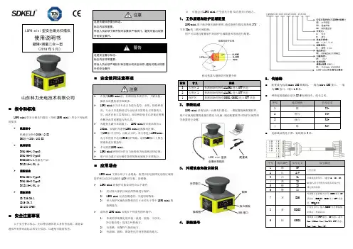
LSPD mini 型安全激光扫描仪使用说明书避障+测量二合一型(2018年5月)山东科力光电技术有限公司⏹指令和标准LSPDmini型安全激光扫描仪(简称LSPD mini)符合下列标准的要求欧盟指令机械安全指令2006/42/EC EMC指令2004/108/EC欧洲标准EN61496-1(Type3)EN61496-3(Type3)EN60825-1(1类激光产品)EN13849-1(PL d)国际标准EN61496-1(Type3)EN61496-3(Type3)EN13849-1(PL d)国家标准GB/T19436.1GB19436.3GB4208(IP65)⏹安全注意事项以下安全警示标志,用以警告潜在的人身伤害危险,请务必遵从所有带有此标志的安全信息,以避免可能的伤害。
注意这是关键信息提示标志。
标志内容很重要。
作业人员必须了解并按内容要求严格执行,避免可能出现意外的安全事件。
警告这是安全警示标志。
标志内容非常重要。
作业人员必须严格执行标志提示的安全信息,避免可能出现意外的安全事件⏹安全使用注意事项注意在使用LSPD mini前,仔细阅读本说明书,了解安装、操作及设置的程序和要求。
LSPD mini应当由专业人员进行选型、安装、检修和保养。
专业人员是指经过专业培训并取得认可资格的人员,或者有着丰富的知识、培训和经验且已经被证明拥有解决此类问题能力的人员。
为避免光路打在地面上,LSPD mini的安装高度应≧200mm。
安装时尽量使LSPD mini远离振动区域。
当USB接口打开时,应防止水汽、灰尘等进入LSPD mini。
为了在使用中达到IP65防护等级,请将USB接口上黑色的密封盖压紧盖好。
不可跌落LSPD mini。
LSPD mini使用时应符合当地的相关标准和法律法规。
用户应当建立安全操作管理的规章制度并有效执行。
⏹应用场合LSPD mini 主要应用于工业现场,典型应用包括固定危险区域的防护和自动导引运输车(AGV)的导航、防碰撞。


EP-9000二维有线扫描枪说明书连接扫描枪将扫描枪连接到附带线缆的专用接头,另一端插入电脑对应的USB端口。
可以在电脑上打开一个Excel表格,用扫描枪扫描商品上的条码,Excel表格里有数据显示即可正常使用。
接口模式本扫描枪支持USB键盘、USB转串口、串口的接口模式。
扫描下面的条码可以将扫描枪配置为USB键盘模式。
USB键盘(默认)扫描下面的条码可以将扫描枪配置为串口模式(需要串口专用线才可输出数据)。
串口扫描下面的条码可以将扫描枪配置为USB转串口模式。
(需要安装驱动,请与销售商联系)USB转串口版本号版本号产品默认配置扫描下面条码可将产品恢复为出厂默认配置。
恢复出厂默认配置扫描模式按键扫描(默认)自感应模式屏幕读取模式当选择此模式时,您的扫描平台将优化为可读取手机或者电脑等显示屏中显示的条码。
不过打开此模式可能造成读取印刷条码的速度稍有降低。
屏幕读取模式关(默认)屏幕读取模式串口波特率配置波特率4800波特率9600(默认)波特率19200波特率38400波特率57600波特率115200汉字输出模式英文(默认)简体中文(记事本/excel)简体中文(Word)发票码功能关闭发票码功能(默认)打开发票码功能为保证发票内容正确输出,打开发票码功能时,请将汉字输出模式配置成简体中文(记事本/excel)。
发票类型选择专用发票(默认)普通发票蜂鸣器配置音量大小音量低音量高(默认)结束符不使用结束符结束符设置为回车结束符设置为回车换行(默认)结束符设置为制表符键盘布局选择Keyboard Layouts美国-英语English(United States)(默认)重码检测用来配置解相同条码的间隔时间,如未超过设置时间,相同条码只会解一次。
重码检测间隔300ms重码检测间隔500ms重码检测间隔750ms(默认)重码检测间隔1s重码检测间隔2s条码类型选择打开/关闭所有条码打开所有条码类型可能会导致解码速度降低,建议根据使用场景自行打开需要的条码类型。


Z-6082全方位激光扫描平台用户手册注意:此激光平台有时会产生无线电射频能量,如果没有按照本手册的指南进行安装和使用,有可能会造成对无线电通信的干扰。
此设备已被测试并达到了A级计算机安全设备标准(EN55022和47 CFP 的第2及第15部分)。
这些设计使产品在使用过程中尽量避免对商业环境造成无线电干扰。
CE标准:Z-6082完全符合CE标准。
但请特别注意采用带有CE认证标志的ZEBEX电源。
注明:本手册所有内容同时适用于Z-6086激光扫描平台,唯Z-6086增加有EAS防盗消磁线圈。
声明:ZEBEX是巨豪实业股份有限公司的注册商标,本手册中提到的其余商标都属于相应公司所有。
本手册的内容可能会被更改或更新而不另行通知,本手册所提供的信息也可能不够准确,ZEBEX 公司对此不承担任何法律责任。
版权所有,未经ZEBEX公司授权不得转印、复制或出售本文档的任何内容,本手册最终解释权归ZEBEX公司所有。
版本号:2007-01■目录介绍 (1)拆包 (2)外观及说明 (2)电源连接 (3)扫描测试 (3)固定安装 (5)连接到PC/POS (6)如何扫描 (8)扫描方法 (8)指示灯 (8)蜂鸣器指示 (8)休眠 (9)通过主机控制激光平台 (10)激光平台维护 (10)激光安全 (11)附录A:接线与脚位定义 (12)附录B:规格及尺寸 (13)附录C:问题解析 (15)附录D:激光平台产品基本设定 (16)附录E:激光扫描平台条码设定 (18)一.恢复出厂设置 (18)二.显示产品信息 (19)三.接口的设定 (19)四.串口参数设定 (23)五.条码数据后附加参数 (25)六.开放与关闭不同码制 (30)七.声音设定 (39)八.休眠时间设定 (42)九.同一条码扫描时间间隔 (46)十.给条码加标识符 (47)十一.设定读码长度范围 (49)十二. 条码加载前缀或后缀 (53)十三.截除条码字符 (55)附录F Full ASCLL码 (57)Z-6082采用了ZEBEX公司2004年研制的Dual-Laser技术和Z-SCAN ASIC芯片。


D a t a l o g i cm a g e l l a n2200v s 柜台嵌入式扫描平台福州条码扫描器Datalogic Magellan 2200vs 柜台嵌入式扫描平台得利捷Magellan 2200VS 是一个二维扫描平台,为中等容量至高容量零售点 (POS) 交易的非常小型柜台收银环境量身定制,特别适用于药店、便利店、小型到中等规模的杂货店、DIY店、专卖店。
全方位为零售商精心打造。
先进的软件解码算法,提供业界最佳的扫描速度,同时改善了对损坏、起皱、或印刷质量差的条形码的读码一次性通过率,从而提高了在零售付款台的运营效率。
Magellan 2200VS 扫描器是专为在紧凑、垂直方式应用并需要高性能的零售商而设计的。
闪存可轻松升级软件,助于延长零售商的投资寿命。
此外,能以各种方式使用辅助 RS – 232 端口,包括增加手持扫描仪、对扫描器进行编程和配置、或访问扫描器标签的数据输出。
对于需要电子商品防盗系统 (EAS) 的应用,2200VS 可内置Checkpoint EAS和支持 Sensormatic EAS 系统,并能通过辅助 RS-232 端口提供条形码识读成功的信号。
选配的增值功能提供可选的信息工具,可通过在扫描仪软件和诊断方面管理信息来帮助降低前端成本。
由于优越的人体工学和通过率,2200VS凭借其在同级别中领先的性能,证明了Magellan 品牌的高质量和可靠性。
闪存可轻松升级软件,有助于延长零售商的投资寿命。
此外,能以各种方式使用辅助 RS – 232 端口,包括增加手持扫描仪、对扫描器进行编程和配置、或访问扫描器标签的数据输出。
对于需要电子商品防盗系统 (EAS) 的应用,2200VS 可内置Checkpoint EAS和支持 Sensormatic EAS 系统,并能通过辅助 RS-232 端口提供条形码识读成功的信号。
选配的增值功能提供可选的信息工具,可通过在扫描仪软件和诊断方面管理信息来帮助降低前端成本。