德国STEINEL 2010 2310 等热风枪发热芯检测
- 格式:doc
- 大小:199.50 KB
- 文档页数:7
散热片(heat sink)检验规范目的:此规范之目的用于判断Heat Sink产品外观之可接受及不可接受之标准。
适用范围:本规范适用于各种制程技术制作之Heat Sink外观检验。
(若客户的特殊要求时,以该合约要求之文件优先。
)规格文件优先权:当遇到不同规格文件冲突时,请依以下优先权3-1 针对限度样品或允收条件所订定之规格3-2 采购订单或指定之合约3-3 Delta工程图面及规格3-4 此份外观检验规范抽样标准:依据MIL – STD - 105E 收样表,一般检验水准Ⅱ,AQL 1.0 抽样标准实旋抽样检验。
检验环境条件、设备及表面等级:5-1 检验环境条件:5-1-1 温度及湿度:常温20℃±8℃、湿度:常湿45%~85%。
5-1-2 照明:400~500烛光之白色萤光性照明设备,眼睛与受检面成45°左右。
5-1-3 目视距离:表面Class A / B 45cm,Class C 60cm。
5-1-4 检验时间:表面Class A 10秒/面,Class B 5秒/面,Class C 3秒/面。
5-2 检验设备:透明塑胶尺、游标卡尺、高度规、工作平台、表同粗度计、投影仪等。
5-3 表面等级:Class A表面检视时必须翻转检视面以得到最大反射光线,Class B / C 表面检视时则不可翻转检视表面。
于检视表面时不可使用辅助之仪器将检视面放大,负责检视人员也必须经过适当这训练。
请依以下检视图示Class A (Viewing Conditions)Class B (Viewing Conditions)Class C (Viewing Conditions)检验标准:6-1 成品外观:依台达电子工程图面。
6-2 供应商提供相关品质证明文件:6-2-1 材质证明文件6-2-2 出货检验报告(EX:尺寸、拉拔力量测试数据、膜厚测定资料等。
)Heat Sink 种类及表面等级定义:7-1 Heat Sink 种类7-1-1 铝挤型(Extruded Heat Sink)7-1-2 铝压铸(Die-Casting Heat Sink)7-1-3 锻造(Forging Heat Sink)7-1-4 堆叠型(Stacked Heat Sink)7-1-5 折叠型(Folder Heat Sink)7-1-6 刨、削型(Skive Heat Sink)7-1-7 冲压型(Stamping Heat Sink)7-1-8 机械加工(Machining Heat Sink)7-2 Heat Sink 表面等级定义缺点类型:8-1 外观8-1-1 有感刮痕:一般露出底材或深度较深(大于0.25mm),用指甲可以感觉出来。
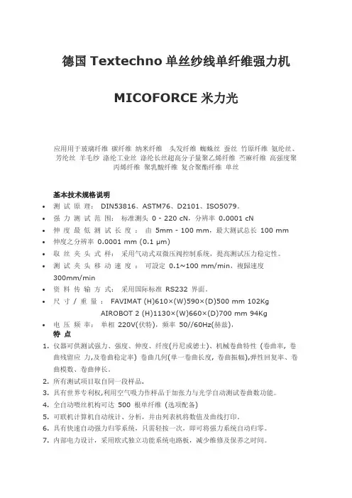
德国Textechno单丝纱线单纤维强力机MICOFORCE米力光应用用于玻璃纤维碳纤维纳米纤维头发纤维蜘蛛丝蚕丝竹原纤维氨纶丝、芳纶丝羊毛纱涤纶工业丝涤纶长丝超高分子量聚乙烯纤维苎麻纤维高强度聚丙烯纤维聚乳酸纤维复合聚酯纤维单丝基本技术规格说明∙测试原理:DIN53816、ASTM76、D2101、ISO5079。
∙强力测试范围:标准测头0 - 220 cN,分辨率0.0001 cN∙伸度最低测试长度:由5mm - 100 mm,最大测试总长100 mm ∙伸度之分辨率0.0001 mm (0.1 μm)∙取丝夹头式样:采用气动式双微压阀控制系统,提高测试压力稳定性。
∙测试夹头移动速度:可設定0.1~100 mm/min,複歸速度300mm/min∙资料传输方式:采用国际标准RS232 界面。
∙尺寸/ 重量:FAVIMAT (H)610×(W)590×(D)500 mm 102KgAIROBOT 2 (H)1130×(W)660×(D)700 mm 94Kg∙电压频率:单相220V(伏特),频率50//60Hz(赫兹),特点1.仪器可供测试强力、强度、伸度、纤度(丹尼或徳士)、机械卷曲特性(卷曲率, 卷曲残留应力,及卷曲稳定率) 卷曲几何(单一卷曲长度, 卷曲振幅),弹性回复率、卷曲模数、卷曲伸长。
2.所有测试项目取自同一段样品.3.具有世界专利权,利用空气吸力作样品于加张力与光学自动测试卷曲数功能。
4.全自动喂丝机构可达500 根单纤维(选项配备)5.可联机计算机自动统计、分析,并由列表机将数值及曲线打印。
6.具有快速自动强力归零系统,只需轻按一次,即可将强力系统自动归零。
7.内部电力设计,采用欧式独立功能系统电路板,减少维修及保养之时间。
8.可依不同纤维种类侧测试之需要,设定断点伸度之百分比(%),配合制程分析之用。
9.可设定参考强度及伸度点,并自动打印测试,及设定曲线中之杨氏系数(Modulus%)配合制程分析之用,亦可设定管制强伸度上下限功能。

拆焊台核查方法我一开始弄这个拆焊台核查呀,真的是一头雾水,就是瞎摸索。
我试过不少方法,现在多多少少有点经验了,就跟你唠唠。
首先呢,你得看看拆焊台的外观。
我就有一次,拿到拆焊台,只顾着检查功能,结果差点犯了大错。
这外观就像是人的衣服,你得看看有没有裂缝啊,破损啊啥的。
要是有裂缝,就可能影响内部构造,就好比衣服破了个洞,风可能就直接灌进去了是一个道理。
然后就是电源部分,这可是拆焊台的动力源泉。
我一开始总是忽略这个,结果有一次怎么都没法正常工作,才发现是电源线有点松动,接触不良。
你可以把电源线摇一摇,拽一拽,按照我自己的这种土办法,要是它时好时坏,那肯定这儿有问题。
这就像水龙头,有时候出水断断续续,那肯定是水管子哪里出故障了。
再说说那个加热头。
我之前对这个加热头啊,不知道怎么去判断好坏。
我就自己想办法,我把它加热到一定温度,然后用个小锡丝去接触,要是锡丝很快就熔化了,说明加热头能正常发热。
就好比炒菜的时候,你看锅够不够热,往锅里滴一滴水,要是“呲啦”一声很快就变成水汽了,那锅就热了。
要是锡丝半天都没反应,那就可能加热头有问题。
还有个温度调节的功能。
这个我开始的时候理解错了。
我以为只要能加热就行,只要把温度调高就肯定能工作。
可是有一次处理一个特别精细的焊点,我把温度调得太高,差点把周围的元件都弄坏了。
所以呢,你要把温度调到不同的数值,看看拆焊台的反应是不是正常。
比如说从低温到高温慢慢调,看看加热头的加热速度是不是均匀的变化。
还有那个拆焊台的支架,这东西看似不重要,我之前也不当回事儿。
结果有次在工作过程中,发现没有个稳固的支架,整个拆焊台摇摇晃晃的,就像一个人站在软绵绵的地上一样不平衡。
这样的话根本没法好好工作。
所以一定要检查支架是不是牢固,有没有变形之类的。
还有些拆焊台可能有一些特殊功能,像有的有个什么智能休眠功能。
这个我当时不确定怎么检测。
后来我就长时间不操作它,然后再按照说明书上的方法去唤醒它,看它能不能正常被唤醒。
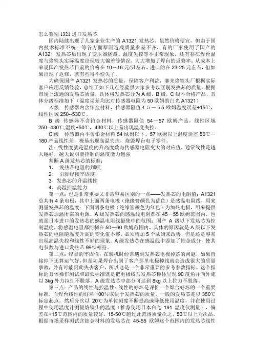
怎么鉴别1321进口发热芯国内陆续出现了几家企业生产的A1321发热芯,虽然价格便宜,但由于国内技术标准不统一等各方面原因造成质量参差不齐,有的厂家使用了国产的A1321发热芯后出现了变压器烧毁、温度失控等不正常现象,还有存在焊台温度与烙铁头实际温度出现较大偏差等情况,大大增加了焊台的返修率;从成本上来说国产发热芯目前的价格在10-16元/只左右,进口的在23-25元左右,但如果出现了返修,就有些得不偿失了。
为确保国产A1321发热芯的质量,保障客户利益,赛光烙铁头厂根据实际客户应用反馈经验,总结了如下几点经验供大家参考以区别发热芯的质量。
根据市场上流通的发热芯质量,具体将发热芯分为A级,B级,C级不合格产品,具体分级标准如下(温度误差均比对传感器电阻为50欧姆的白光A1321)A级传感器内含铂金材料,传感器阻值45-55欧姆温度误差+15℃,线性区域250--530℃。
B级传感器不含铂金材料,传感器阻值54-57欧姆产品,线性区域250--430℃,温度+50℃,430℃以上易出现温度失控。
C级传感器内不含铂金材料54欧姆以下、57欧姆以上温度误差50℃-180产品线性差,极易出现高温失控,烧毁焊台电子零件。
注:线性度就是温度的升高度数与传感器电阻变大的对应值,通常线性是越大越好,越大说明能控制的温度能力越强判断A级发热芯的标准:1、发热芯电阻的判断;2、引脚焊接牢固度;3、发热芯的升温线性4、高温控温能力第一点:也是非常重要又非常容易区别的一点——发热芯的电阻值;A1321总共有4条电极,其中上面两条电极(绝缘管颜色为蓝色)是感温电阻线,用来测量发热芯的温度;下面两条电极(绝缘管颜色为红色)为加热电极,用来提供发热芯加温所需的电源。
A级发热芯的感温线电阻都在45-55欧姆范围内,也就是日本进口的发热芯的感温电阻线最集中的范围;国产A级以下发热芯为控制温度,将感温电阻都控制在50-60欧姆范围内,具体的原因就是A级以下发热芯的电阻随温度升高的变化值不够,必须增加5个欧姆来改善,但是还是容易出现高温失控和线性不好的现象。
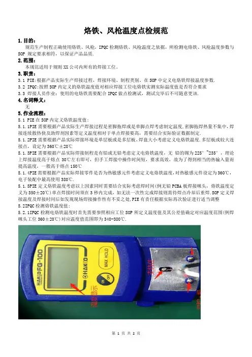
烙铁、风枪温度点检规范1.目的:规范生产制程正确使用烙铁、风枪,IPQC检测烙铁、风枪温度之依据,所检测电烙铁、风枪温度参数与SOP 规定要求相符,以保证产品品质.2.范围:本规范适用于规则XX公司内所有的焊接工位。
3.职责:3.1 PIE:根据产品实际生产焊接过程、焊接环境、制程类别、在SOP中定义电烙铁焊接温度参数.3.2 IPQC:按照SOP内定义的烙铁温度值对相应焊接工位电烙铁实测实际温度值是否符合要求3.3 焊接人员作业:使用的电烙铁需要配合IPQC做点检测试,测试完毕后不可随意更该.4.名词释义:无5.作业流程:5.1 PIE在SOP内定义烙铁温度值:5.1.1PIE需要根据产品实际生产焊接过程是密脚拖焊或是单脚点焊考虑制定温度,密脚拖焊热量不集中,焊接连续散热快及助焊剂因素等定义温度相对于单点焊接要高,需要结合实际验证数据制定.5.1.2PIE需要根据产品实际焊接环境是单层板或是多层板、焊盘大小考虑定义电烙铁温度.多层板或较大连接点,设定为360℃±20℃5.1.3PIE需要根据产品实际焊接制程是有铅或无铅考虑定义电烙铁温度,无铅的锡为225°~235°,理论上焊接温度高于熔点30℃左右即可,但手工焊接中操作时间短,要求高效,故为了得到相当的热输入量而提高温度,一般高于熔点150℃5.1.4PIE需要根据产品实际焊接零件是否为热敏感元件考虑定义电烙铁温度,对热敏感元件设定为360℃,电子装配中最高使用380℃.5.1.5PIE定义烙铁温度考虑以上因素同时需要结合实际考虑焊时间(例无铅PCBA板焊接咪头,烙铁温度定义为350±20℃)单点焊接时间须在3秒内完成,如无法一次性完成焊接则需待焊点冷却后重焊.SOP定义焊接温度及焊接时间后如发现现场焊接操作性有不妥之处,PIE有责任根据实际再次验证进行适当调整5.2IPQC检测烙铁温度值:5.2.1IPQC检测电烙铁温度时首先需要参照相应工位SOP所定义温度值及其公差值确定对应温度范围(例焊咪头工位360±20℃)对应温度值范围即为340-380℃.SOP-TD-C-012 A REV.0-2018.03.225.2.2确认温度测试仪的电池电量以及显示效果,将温度测试仪的开关拔到“ON”位,开启电源,观察数显屏幕显示的数值是否清晰可见,将温度测试仪置于室温下约3分钟,观察数显屏幕所显示的温度数值,然后与室内温度计的温度值进行对比,如果数值差别在±3℃以内,判定温度测试仪OK,可以用于检测烙铁温度。

Products > Heat Guns Heat Guns Glue Guns Exterior Lights Sensors Voltage Testers ELECTRONIC HEAT GUNSSTEINEL Electronic Heat Guns are ideal for applications requiring precisetemperature control such as shrink tubing or welding plastics. Electronic control makes itpossible to restrict airflow through pin-point reduction nozzles used for soldering sink wireconnectors, de-soldering circuit boards, shrinking small diameter tubes. Also can be used toweld with narrow-slit nozzles.Electronic thermo couple control is what sets these heat guns apart. This feature continuousmonitors and adjusts output to maintain a consistant temperature and avoid overheating.You can count on STEINELheat guns for precision, durability and long life.Roofing Welding PlasticMaterialsButt-weldingPVCSoldering &De-solderingShaping Plastic Sealing VinylFlooringApplying ShTubesHG 3002 LCDElectronically monitored heat gun with variable airflow and digital temperaturedisplay for precise control.Temperature Continuously variable 120°F – 1100°F.Airflow Continuously variable up to 17.6 cfm with selectablecool air stage.LCD Displays temperature output in 10°F increments.Double Insulated Power Cord Rubber construction for increased safety.Output1,500 watts.Voltage120 VAC / 60 Hz.Certifications UL / CSA.Full One Year Warranty Refer to owner's manual for details.AccessoriesAccepts a full range of nozzles and accessories.HG 2002 LEElectronically monitored heat gun with 3-stage airflow and LED temperature rangeindicator.Temperature Continuously variable 120°F – 1100°F.3-Stage Airflow Stage 1: cool air at 17.6 cfmStage 2: 9.5 cfmStage 3: 17.6 cfmLED Display Diodes indicate temperature range selected. Double Insulated Power Cord Rubber construction for increased saftey.Output1,500 watts.Voltage120 VAC / 60 Hz.Certifications UL / CSA.Full One Year Warranty Refer to owner's manual for details. AccessoriesAccepts a full range of nozzles and accessories.HG 2000 EElectronically controlled heat gun with constant air flow.Lightweight , ergonomically designed.Temperature Continuously variable 120°F – 1100°F.Constant Airflow14.8 cfm.Ergonomic Design Lightweight (21.7 oz.) and easy to use, even in tightquarters.Double Insulated Power Cord Rubber construction for increased saftey.Output1,500 watts.Voltage120 VAC / 60 Hz.Certifications UL / CSA.Full One Year Warranty Refer to owner's manual for details. AccessoriesAccepts a full range of nozzles and accessories.HG 1802 EElectronically monitored heat gun with variable temperature and 3 stage airflow. Temperature Continuously variable 120°F – 1100°F.3 Stage Airflow Stage 1: cool air at 17.6 cfmStage 2: 9.5 cfmStage 3: 17.6 cfmDouble Insulated Power Cord Rubber construction for increased safety.Output1,500 watts.Voltage120 VAC / 60 Hz.Certifications UL / CSA.Full One Year Warranty Refer to owner's manual for details. AccessoriesAccepts a full range of nozzles and accessories.。
西威变频器调试资料一. 变频器线路说明1。
同步变频器选型方法2。
与常见微机板匹配注意事项(蓝光、新时达、中秀、奔克、里霸)3。
与常用曳引机匹配注意事项(蓝光、欣达、孚信、阿尔法、蒙特纳利、威特)4。
端子与接线说明二。
外部部件说明与选配1。
制动电阻选型2. 滤波器选型3. 编码器与分频卡海德汉hipeface内密控4. 旋转变压器与RES卡三。
操作说明1。
面板操作说明2。
参数修改步骤3。
参数保存方法四。
参数设置表及简要说明五. 变频器自学习调试1。
电流自学习2. 无齿定位自学习六。
速度曲线与时序的说明七. 舒适感调试说明1。
PI调节2。
预转矩调试八。
常见显示错误与处理方法1. 报警清除方法2。
软件报错的说明3。
硬件故障处理方法九。
3.5与3.4新增、改变内容对照表十。
附录1 3.5版本说明十一。
反馈表一。
变频器线路说明1。
同步变频器选型方法当永磁同步无齿曳引机选配变频器型号时,除了要符合曳引机的铭牌参数外,一般还需要满足1.6 Ib>2。
0Ij,的电流公式。
Ib:变频器的额定电流。
Ij:曳引机的额定电流。
2. 与常见微机板匹配注意事项(蓝光、新时达、中秀、奔克、里霸)(未完善)因西威变频器软件系统比较强大,启动时比一般变频器要慢.在电梯系统上电后,变频器正常信号给的比较慢,新时达微机板等会不断的断合变频器电源,从而无法正常运行运行。
具体处理方法:将变频4060号参数置1(反),微机板中Drive OK输入端设为常闭有效。
3。
与常用曳引机匹配注意事项(蓝光、欣达、孚信、阿尔法、蒙特纳利、威特)(未完善) 进口曳引机参数不详,,具体参数要向曳引机销售方咨询。
4. 端子与接线说明(详细参见说明书P50)a、主线路注意事项制动电阻应接在BR1和C之间,不能接在C和D或者D和BR1之间,如果接错会损坏变频器"主线路端子在接线时要拧紧,不然会影响变频器和电机性能,容易产生故障"b、控制线路注意事项采用变频器内部24V时,需要将变频器18、19端子接入回路。
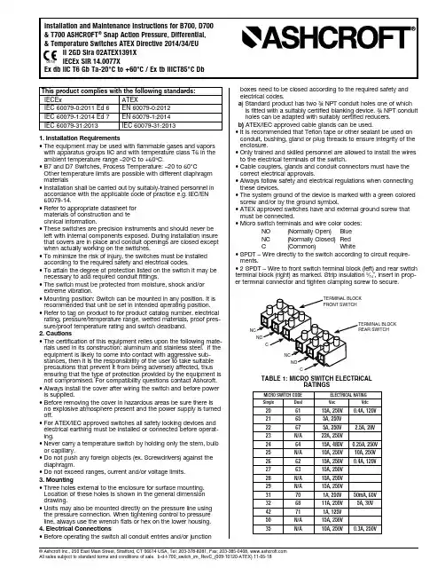
© Ashcroft Inc., 250 East Main Street, Stratford, CT 06614 USA, Tel: 203-378-8281, Fax; 203-385-0408, All sales subject to standard terms and conditions of sale. b-d-t-700_switch_im_RevC_(009-10120-ATEX) 11-05-181. Installation Requirements • T he equipment may be used with flammable gases and vapors with apparatus groups IIC and with temperature class T6 in the ambient temperature range –20ºC to +60ºC.• B 7 and D7 Switches, Process Temperature: – 20 to 60°COther temperature limits are possible with different diaphragm materials • I nstallation shall be carried out by suitably-trained personnel in accordance with the applicable code of practice e.g. IEC/EN 60079-14.• R efer to appropriate datasheet for materials of construction and te c hnical information.• T hese switches are precision instruments and should never be left with internal components exposed. During installation insure that covers are in place and conduit openings are closed except when actually working on the switches.• T o minimize the risk of injury, the switches must be installed according to the required safety and electrical codes.• T o attain the degree of protection listed on the switch it may be necessary to add required conduit fittings.• T he switch must be protected from moisture, shock and/or extreme vibration.• M ounting position: Switch can be mounted in any position. It is recommended that unit be set in intended operating position.• R efer to tag on product to for product catalog number, electrical rating, pressure/temperature range, wetted materials, proof pres-sure/proof temperature rating and switch deadband.2. Cautions • T he certification of this equipment relies upon the following mate-rials used in its construction: aluminum and stainless steel. If the equipment is likely to come into contact with aggressive sub-stances, then it is the responsibility of the user to take suitable precautions that prevent it from being adversely affected, thus ensuring that the type of protection provided by the equipment is not compromised. For compatibility questions contact Ashcroft.• A lways install the cover after wiring the switch and before power is supplied.• B efore removing the cover in hazardous areas be sure there is no explosive atmosphere present and the power supply is turned off.• F or ATEX/IEC approved switches all safety locking devices and electrical earthing must be installed or connected before operat-ing.• N ever carry a temperature switch by holding only the stem, bulb or capillary.• D o not push any foreign objects (ex. Screwdrivers) against the diaphragm.• Do not exceed ranges, current and/or voltage limits.3. Mounting • T hree holes external to the enclosure for surface mounting. Location of these holes is shown in the general dimension drawing.• U nits may also be mounted directly on the pressure line using the pressure connection. When tightening control to pressure line, always use the wrench flats or hex on the lower housing.4. Electrical Connections • B efore operating the switch all conduit entries and/or junctionboxes need to be closed according to the required safety andelectrical codes. a ) S tandard product has two ¾ NPT conduit holes one of whichis fitted with a suitably certified blanking device. ¾ NPT conduit holes can be adapted with suitably certified reducers. b) ATEX/IEC approved cable glands can be used.• I t is recommended that Teflon tape or other sealant be used on conduit, bushing, gland or plug threads to ensure integrity of the enclosure.• O nly trained and skilled personnel are allowed to install the wires to the electrical terminals of the switch.• C able couplers, glands and conduit connectors must have the correct electrical approvals.• A lways follow safety and electrical regulations when connecting these devices.• T he system ground of the device is marked with a green colored screw and/or by the ground symbol.• A TEX approved switches have and external ground screw that must be connected.• Micro switch terminals and wire color codes: NO (Normally Open) Blue NC (Normally Closed) Red C (Common) White • S PDT – Wire directly to the switch according to circuit require-ments.• 2 SPDT – Wire to front switch terminal block (left) and rear switch terminal block (right) as marked. Strip insulation 5⁄16˝, insert in prop-er terminal connector and tighten clamping screw to secure.MICRO SWITCH CODEELECTRICAL RATING SingleDualVa cVdc 20 61 15A, 250V 0.4A, 120V 21 65 5A, 250V 22 67 5A, 250V 2.5A, 28V 23 N/A 22A, 250V 24 64 15A, 480V 0.25A, 250V 25 N/A 10A, 250V 10A, 250V 26 62 15A, 250V 0.4A, 120V27 63 15A, 250V 28 N/A 15A, 250V 29 N/A 15A, 250V 31 70 1A, 250V 50mA, 60V 32 68 11A, 250V 5A, 30V42 71 1A, 125V 50 N/A 15A, 250V35N/A10A, 250V0.3A, 250VTABLE 1: MICRO SWITCH ELECTRICALRATINGSThis product complies with the following standards: IECEx ATEX IEC 60079-0:2011 Ed 6 EN 60079-0:2012 IEC 60079-1:2014 Ed 7 EN 60079-1:2014 IEC 60079-31:2013 IEC 60079-31:2013© Ashcroft Inc., 250 East Main Street, Stratford, CT 06614 USA, Tel: 203-378-8281, Fax; 203-385-0408, All sales subject to standard terms and conditions of sale. b-d-t-700_switch_im_RevC_(009-10120-ATEX) 11-05-185. Adjustment of Setpoin Note – As indicated below, adjustment of setpoint is made by use of 7⁄8˝ nut. Precision switch element mounting screws and bracket adjusting screw are factory sealed and should not be tampered with.B700 Series – A single setpoint adjustment nut (7/8˝) is located centrally at the bottom on the inside of the enclosure.For accurate setpoint calibration, mount the switch on a calibration stand, a pump or catalog No. 1305 deadweight gauge tester. A suitable reference standard such as an ASHCROFT Duragauge or Test Gauge is necessary to observe convenient changes in pressure.As received, the pressure switch will normally be set to approx-imately 90% of the indicated range. Pressurize the s ystem torequired setpoint and turn the adjustment nut until switch changes mode. Direction of turning is indicated on a label affixed to the inside of the switch enclosure. When setpoint has been achieved raise and lower pressure to insure that setpoint is correct.After installation of the switch replace cover to insure electrical safety and to protect internal parts from the environment.Note – Since vacuum models are already above setpoint at atmo-sphere, the Normally Open (NO) circuit will be closed as received.D700 Series – A single setpoint adjustment nut (7/8˝) is located centrally at the bottom on the inside of the enclosure.The direction of turning is indicated on a label affixed to the inside of the switch enclosure.A typical calibration procedure would be as follows: Static Working Pressure - 600 psig Adjustable Differential Range - 5/200 psid Differential Setpoint - 150 psi above static working pressure.Simultaneously raise the high and low side pressure to 600 psig. Maintain the low side pressure at 600 psig. Raise the high side pressure to 750 psig to obtain 150 psi differential.Turn the adjustment nut until the switch changes mode at 150 psi differential. When the setpoint has been achieved, raise and lower the high side pressure to ensure that the differential setpoint is correct.D700 Series (low range differential) – A single setpoint adjust-ment nut (7⁄8˝ ) is located centrally at the bottom on the inside of the enclosure.The direction of turning is indicated on a label affixed to the inside of the switch enclosure. XG5 switches have a setpoint indication scale adjacent to the adjustment nut. To adjust the switch, align the top of the adjustment nut hex with the indicator line on the scale. Do not force adjustment or attempt to ex-ceed the maxi-mum setting shown on the scale or nameplate.For accurate setpoint calibration or for switches without a scale mount the switch on a calibration stand so that the HIGH and LOW pressures expected under operating conditions may be obtained. Suitable reference standards are necessary for each pressure.Note – During calibration an approximate setpoint under operating conditions can be obtained by setting the operating point with the low side open to atmosphere. A final setpoint adjustment can be made after installation.Apply LOW pressure. Then apply HIGH pressure to the required setpoint and turn the adjustment nut until the switch operates. When the setpoint has been achieved, raise and lower HIGH pres-sure to ensure that the differential pressure between the HIGH and LOW pressures is correct.After installation of the switch, replace the cover to ensure electri-cal safety and to protect the internal parts from the e nvironment.T700 Series – A single setpoint adjustment nut (7⁄8˝ ) is located cen-trally at the bottom on the inside of the enclosure.The bulb of the switch should be immersed in a bath at the desired setpoint temperature. Optimum performance will be obtained if the bulb is fully immersed. Allow five minutes for initial stabilization.As received, the temperature switch will normally be set to approx-imately 90% of the indicated range. After stabilization, turn the adjustment nut until switch changes mode. Direction of turning is indicated on a label affixed to the inside of the switch enclosure. When setpoint jas been achieved raise and lower temperature to insure that the setpoint is correct.After installation of the switch replace cover to insure electrical safety and to protect internal parts from the environment.B750, D750 and T750 Variable Deadband Switches – Deadband is varied by rotating the wheel on the precision switch. Whenviewed from the front of the enclosure, rotation to the left increases deadband – rotation to the right decreases deadband. Letters on the wheel may be used as a reference. Deadbands obtainable will vary from 0.5% to 9% of pressure or temperature range depending on range segment and type of diaphragm.Adjustment of Setpoint – As received, the switch will normally be set to approximately 90% of range. Rotate the wheel on the MICRO SWITCH all the way to the right; this will provide small-est deadband. Pressurize, or increase bath temperature, to the required setpoint and turn the adjustment nut until the switch changes mode. Lower the pressure to reset the switch. Rotate the wheel on the MICRO SWITCH until the desired deadband is obtained. The upper setpoint will be changing upward with this adjustment. Lower the pressure to reset the switch. Then increase the pressure to the desired setpoint and turn the adjusting nut until the switch changes mode. Lower the pressure and check reset-point and deadband.6. Specific Conditions of Use • P rior to use, the equipment shall be subjected to a pressure test, which shall be based on the process pressure of the associated system. If available, the test shall be conducted in accordance with the requirements of an applicable industry standard. The pressure shall be applied from the system side of the diaphragm. It must be proven that there is no leakage of the test medium into the flameproof enclosure and that the flameproof enclosure does not become pressurized above ambient atmospheric pressure.• E poxy coated enclosures are non-conducting and may generate an ignition-capable level of electrostatic charges under certain extreme conditions. The user should ensure that the equipment is not installed in a location where it may be subjected to external conditions (such as high-pressure steam) which might cause a build-up of electrostatic charges on non-conducting surfaces. Additionally, cleaning of the equipment should be done only with a damp cloth. • S witch vent must not be used nor blocked.• I n accordance with clause 5.1 of IEC/EN 60079-1 the critcal dimensions of the flamepaths are:• Never use aggressive solvents.• Do not use high-pressure water to clean the switch.8. Maintenance/Troubleshooting• All ASHCROFT switches require little or no maintenance.• I nspection and maintenance of this equipment shall be carried out by suitably trained personnel in accordance with the applica-ble code of practice e.g. IEC/EN 60079-17.• Be sure that the case is closed at all times.• W hen the switch is exposed to process media that may hard-en and/or build up in the pressure port, the switch should be removed and cleaned as needed.• I f the switch does not function, only trained and skilled personnel should check on the wiring, power supply and/or mounting.• I f the problem cannot be solved, do not attempt to repair, please contact Ashcroft or Ashcroft distributor.© Ashcroft Inc., 250 East Main Street, Stratford, CT 06614 USA, Tel: 203-378-8281, Fax; 203-385-0408, All sales subject to standard terms and conditions of sale. b-d-t-700_switch_im_RevC_(009-10120-ATEX) 11-05-18。
天行健,君子以自强不息;地势坤,君子以厚德载物;行盛于言。
一箪食,一飘饮,在陋巷,人不堪其忧,回也不改其乐。
苏州默纳克NICE-3000故障代码海纳百川.2009.12.1.1.E01—逆变单元保护。
原因:主回路输出接地或短路;曳引机连线过长;工作环境过热;控制器内部连线松动。
处理:排除接线等外部问题;加电抗器或滤波器;检查风道与风扇是否正常;联系厂家。
2.E02—加速过电流。
原因:主回路输出接地或短路;电机参数调谐与否;负载太大。
处理:排除接线等外部问题;进行电机参数调谐;减轻突加负载。
3.E03—减速过电流。
原因:主回路输出接地或短路;电机参数调谐与否;负载太大;减速曲线太陡。
处理:排除外部接线等问题;进行电机参数调谐;减轻突加负载;调节曲线参数。
4.E04—恒速过电流。
原因:主回路输出接地或短路;电机参数调谐与否;负载太大;码盘干扰大。
处理:排除接线等外部问题;进行电机参数调谐;减轻突加负载;选择合适码盘,采用屏蔽线连接。
5.E05—加速过电压。
原因:输入电压过高;电梯倒拉严重;制动电阻选择偏大,或制动单元异常;加速曲线太陡。
处理:调整输入电压;调整电梯运行启动时序;选择合适制动电阻;调整曲线参数。
6.E06—减速过电压。
原因:输入电压过高;制动电阻选择偏大;或制动单元异常;减速曲线太陡。
处理:调整输入电压;选择合适制动电阻;调整曲线参数。
7.E07—恒速过电压。
原因:输入电压过高;制动电阻选择偏大,或制动单元异常。
处理:调整输入电压;选择合适制动电阻。
8.E08—控制电源故障。
原因:输入电压过高;驱动控制板异常。
处理:调整输入电压;与厂家联系。
9.E09—欠电压故障。
原因:输入电源瞬间停电;输入电压过低;驱动控制板异常。
处理:排除外部电源问题;联系厂家。
10.E10—系统过载。
原因:抱闸回路异常;负载过大。
处理:检查抱闸回路及电源;减小负载。
11.E11—电机过载。
原因:FC-02设定不当;抱闸回路异常;负载过大。
说明书温度感应器PR-SPA-EX-NWT1.生产与销售 EPHY-MESS GmbH电话: +49 6122 9228-0 Berta-Cramer-Ring 1 传真: +49 6122 9228-99 65205 威斯巴登电子邮件:*****************德国2.标准依据DIN EN 60079-0:2012 + A11:2013 (IEC 60079-0:2011, 修改 + 修订版:2012 + 修订版:2013)DIN EN 60079-7:2015 (IEC 60079-7:2015)DIN EN 60079-11:2012 (IEC 60079-11:2011 + 修订版:2012)DIN EN 60079-31:2014 (IEC 60079-31:2013)3.标识3.1 防爆类型增安型IBExU 14 ATEX 1281U_IECEx IBE 14.0058 U_II 2G Ex eb IIC Gb mm_ yy 0637 T min [°C] ≤ TA ≤ T AB-Nr.-Pos.Nr.Sn.-Nr. xxxx U 标识依据说明书3.2 防爆类型的本质安全型0637 T AB-Nr.-Pos.Nr. ≤ s. Punkt 6 BDA 标识依据说明书4.安装4.1 安装于电机凹槽中在电机(例如电动机,发电机或变压器)凹槽中安装该温度感应器时,没有特殊事项需要遵守。
该感应器尺寸适合在电气设备的凹槽中直接固定安装。
优秀的设计让被监测的组件和温度传感器之间有着良好的热接触。
传感器平行于绕组安装进预设的插槽中。
在组装和操作过程中,必须避免温度传感器过度弯曲(折叠)或对某点载荷过大。
安装时注意电线和绝缘层不得有损坏。
布线(连接线)应做好防拉扯措施。
传感器的使用者必须定义和记录防爆类型。
传感器的安装应确保机械安全。
4.2 在电机凹槽以外的地方使用在这种应用情况中,传感器与爆炸性气体有直接接触,应将自热以及由此引起的表面温度升高考虑在内。
摘要随着半导体技术的迅速发展,电子产品的已进入各行各业,涉及航空航天、机械制造、电子商务等,可以说,我们大家的生活已无法离开电子产品。
可焊性测试是电子产品生产制造过程中检验产品可焊接性能的一种必要手段。
产品引线的焊接性能将直接影响到产品的使用,严重的焊接不良甚至会影响到整机的可靠性。
而且此类不良很多是间歇性的,有时会影响维修人员对故障的判断,造成一些不必要的损失。
本文着重介绍了各类可焊性测试方法在元器件生产中的实际应用,以及使用方法中的一些关键点。
通过在工作中的实际应用,结合标准的要点和产品的特点,在不违背标准的情况下,针对各类不同的产品,使用不同的测试方法进行检测,这样能更有效的反应产品的可焊接性能。
特别是针对一些短引脚、无引脚产品,如何使用合适的方法,甚至说使用更有说服力的润湿法来进行检测。
这些方法的研究,将有利于封装厂在生产过程中改进产品电镀品质的检测方法,能更快、更有效的发现产品的电镀缺陷,及时调整生产工艺的,提高产品质量,满足客户的需求。
关键词:可焊性;方法;标准;半导体元器件AbstractWith the rapid development of semiconductor technology, electronic products has entered into all walks of life, involved in aerospace, mechanical manufacturing, electronic commerce and so on, in other words, our life cannot leave the electronic products.Solderability test is a necessary mean to inspect the product solderability during the electronic product manufacturing process. The solderability of the lead will directly affect the product using; serious bad soldering may even affect the reliability of the machine. And such bad soldering is intermittent; sometimes it will affect maintenance personnel’s judgment for fault, causing some unnecessary loss.This article emphatically introduces the practical application of all kinds of solderability test methods in the production of components, and some key points in using the methods. Through practical application, combining the main points of the standard and the characteristics of the products, under the case of without violating the standard, for all kinds of different products, using different testing methods can reflect the solderability more effective. Especially for some short pin and no pin products, how to testby the right method or more persuasive wetting method? The research of these methods will be of conducive forpackaging factory to improve the detection method of improving products electroplating quality in the process of production, and can find plating defects of product faster and more effective to adjust the production technology, improve product quality, and meet customer demand timely.Keywords: Solderability, Methods, Standard, Semiconductor components目录目录摘要 (Ⅰ)Abstract (Ⅱ)第1章绪论 (1)1.1课题研究的目的和意义 (1)1.1.1课题背景 (1)1.1.2目的和意义 (2)1.2 国内外研究现状 (2)1.2.1 课题来源 (2)1.3 课题的主要研究内容 (4)第2章半导体元器件的可焊性描述 (6)2.1 可焊性描述 (6)2.2 测试可焊性的几种主要方法 (6)2.2.1 可焊性测试前处理 (7)2.2.2 助焊剂的使用 (9)2.2.3 焊料的使用 (10)2.2.4 槽焊法 (11)2.2.5 电烙铁法 (12)2.2.6润湿称量法 (13)2.3本章小结 (17)第3章小型短管脚产品使用润湿称量法测试 (18)3.1小型短管脚产品的定义 (18)3.2 设备介绍 (18)3.3 SOT-23产品的测试 (19)3.3.1 SOT-23封装介绍 (19)3.3.2 润湿称量法对SOT-23产品进行测试 (20)3.4本章小结 (22)第4章无外引脚产品的测试 (23)4.1 无外引脚产品介绍 (23)4.2 槽焊法测试 (24)4.3 润湿称量法测试 (25)4.4 本章小结 (26)第5章基板封装产品的测试 (27)5.1基板封装介绍 (27)5.2 槽焊法对基板封装进行测试 (27)5.3 电烙铁法进行补充测试 (29)5.4 本章小结 (29)结论 (30)江苏科技大学硕士论文参考文献 (31)致谢 (33)第1章绪论第1章绪论1.1 课题研究的目的和意义1.1.1课题背景1947年晶体管发明的同时,也开创了半导体封装的历史。
16、MPK708C系统电梯故障手册电梯在调试过程中会出现各种故障,系统的故障记录信息是问题分析,解决的有效途径,本手册详细介绍了MPK708C电梯控制系统、SIEI 变频器提供的各种故障信息及分析解决问题的方。
16.1 MPK708C控制器故障记录图例:1、E1: Security circuit opened解释:安全回路断开原因:变压器TC2保险丝熔断安全回路有开关路动作安全窗、盘车手轮、底坑、轿顶、机房、曳引机急停开关动作解决办法:更换保险丝检查限速器、上/下极限、断绳、缓冲器、安全钳开关检查安全窗、盘车手轮、底坑、轿顶、机房、曳引机急停动作故障显示及恢复方法:楼层显示器可显示,微机记录故障,安全回路恢复正常即可复位故障。
2、E2:Door Lock Opened Or Error解释:门锁故障原因:关门时厅/ 轿门锁不通,超时关门运行时厅/ 轿门锁断开,电梯急停主控器检测点故障解决办法:检查门机检查轿顶板PM709输入输出信号动作是否准确主控器I3.1 , I3.2 输入信号是否正确检查厅/轿门联锁及线路故障显示及恢复方法:楼层显示器可显示,微机记录故障,门锁信号恢复正常即可复位故障。
出现此故障后可能伴有E14出现,电梯到端站重新校正后恢复运行。
3、E3: Can’t Find the Leveling Point解释:电梯减速后超过10秒检测不到门区信号原因:门区开关损坏平层板插入深度少解决办法:更换门区开关平层板至少插入开关2/3故障显示及恢复方法:楼层显示器显示,微机记录故障,检修复位。
4、E4: Can’t Find the Deceleration Point解释:检测不到减速点原因:换速(双稳态)开关故障换速磁铁位置错误变频器分频卡输出脉冲错误或有干扰参数time/floor protect错误解决办法:检查换速(双稳态)开关,并更换1mm调整磁铁位置,磁铁距离开关水平距离6+-通过主控器显示界面观察脉冲信号变化是否正常检测变频器分频模块调整加大time/floor protect参数(默认13S)故障显示及恢复方法:楼层显示器可显示,微机记录故障,出现此故障后可能伴有E14出现,电梯到端站重新校正后恢复运行。
1.适用范围1.1本仪器适用于在电力、石化、冶金等工业领域和环境监测、节能能效测试以及高校科研的燃烧技术分析领域。
电化学传感器可测量6组分烟气参数,红外传感器可测量CO/CO2,综合了烟气压力、温度、流速等参数,是燃烧优化领域和环保监测领域中最理想的分析工具。
2.J2KN烟气分析仪操作步骤2.1烟气分析2。
1。
1连接采样管线和环境/烟气温度探针2.1.2首先打开基础模块;使用方向键选择子菜单“烟气分析”,按<OK>键确认后,仪器便开始为期1分钟的自动校准.校准期间烟气分析仪采样针不能置于烟道内。
2。
1.3然后进入“燃料类型”选项,按手操器键盘中间的〈OK〉键,选好燃料类型(上下键)再按<OK〉键,接下来仪器将询问是否使用数据处理,按F4选择“NO”,先进入主菜单;2.1。
4将采样探针放置于烟道中,以便热电偶和烟气环境充分接触.先确认探管处于烟道气的中心点(探管顶端处于烟气最高温度区域),然后再开始测量。
仪器带有烟气温度中心点搜索功能。
仪器显示“+”的时候,测量的温度在上升,表明探管向温度中心点移动;仪器显示“—”的时候,表明探管正远离向温度中心点,温度在下降.烟气温度稳定超过3秒后,指示符号会消失.2.1。
5正确的测量值会经过短时间的延时后才会显示,原因是烟气在仪器内部传输及传感器稳定的电化学反应积聚都需要时间,所以等待至少2分钟,测量数据稳定后方可记录、打印、保存;2。
2压力测量2.2。
1打开基础模块,使用方向键选择子菜单“压力测量”,会显示当前值和传感器校零指示。
这时从仪器接口处拔下压力管线,等几秒钟后按〈F4〉,传感器即被重新校准.2。
2。
1重新将压力管线插回仪器,就会显示确切的测量值,这时可以按〈内存〉键,可以将其存储到内存中此前的数据组中。
存储值会显示在屏幕上,按〈ESC>退出差压测量菜单.2。
3燃油烟黑测量2.3.1连接采样管线和环境/烟气温度探针2.3。
2首先打开基础模块,使用方向键选择子菜单“燃油烟黑测量”中可以输入锅炉温度、烟黑测量点和燃油油类.2。
德國STEINEL司登利
HG-2310LCD熱風槍维修检测
德國STEINEL司登利HG-2310LCD熱風槍维修检测
注意: 在進行維修檢測前,必須先將電源切斷.並由合格電器技師操作.
德國STEINEL司登利HG-2310LCD熱風槍维修检测
(一)卸下出風口保護罩,防滑手柄及螺絲,打開外
殼. 將各部件移出機殼進行檢測.
(二)檢查各部件(發熱芯、摩打、電路板、開關制、電
源線)是否短路,如短路,先行處理.
(三)參照電路連接圖,測量下列各部件線端的參數.如
需更換新的部件,注意各線端的正確接駁位.
德國STEINEL司登利HG-2310LCD熱風槍维修检测
<I> 發熱芯部份:
使用萬用表"Ω"檔測量電阻值,並記錄結果:
第一步驟:
(A) #1 (橙色線) 與#5 (棕色線) 正常電阻值範圍:
410-490 Ω.
(B)#4 (黑色線) 與#5 (棕色線) 正常電阻值範圍:
25-40 Ω.
(C) #1 (橙色線) 與#4 (黑色線) 正常電阻值範圍:
430-600 Ω.
(D) #2 (綠色線) 與#3 (紅色線) 正常電阻值範圍:
0.1-4.0 Ω.
(E)#11 (灰色線) 與#12 (灰色線) 正常電阻值範圍:
20-100 KΩ.
如上述(B) (D) (E) 三項各組的電阻值必須在正常範圍內爲之合格.如有任何一組不符,即表示
發熱芯已損壞,需要更換.
第二步驟:
<1>如: (A)與(B)測出的電阻值為“∞”, (C)測出的電阻值是正常範圍時,表示晶體管(#32)損壞,需更換.
<2>如: (A)與(C)測出的電阻值為“∞”, (B)測出的電阻值是正常的範圍時,表示啟動線(#33)損壞,需修好.
<3>如需進行<1>或<2>的更換、修復,按如下方法:卸下發熱芯及塑
膠部份上的4個螺絲,將發熱部件由金屬筒內慢慢取出,查看:
(a)加熱絲(#31)﹑測量點(#34)是否短路,陶瓷部份(#35)是否
嚴重破碎,如有上述任何一种情形,表示發熱芯無法修復,需
更換.
(b)更換晶體管(#32)的步驟: [ 晶體管規格為:( 230AV 240℃
熱保護管) ] .
(1)將晶體管(#32)尾部的管腳〔連接啟動絲(#33)〕靠晶
體管邊剪斷.
(2)將金屬三葉片(#37)用尖咀鉗拉直,並保留鐵片及隔熱
片,以便還原時裝上.
(3)將黑色固定膠殼(#36)的安裝位置記下後卸下備用,如
已溶化及嚴重破裂,需更換.
(4)將舊有晶體管另一端(前端),卸除收縮管,及與棕色線
(#5)的連接, 在將新的晶體管前端用金屬卡扣接好棕
色線(#5),在收縮管內包好
(5)把前端已接好棕色線(#5)的新晶體管尾端,用金屬卡
扣連接舊有晶體管尾部〔連接啟動絲(#33)〕的管腳,
並用無鉛焊錫焊好.
(6)還原各部件.
(c)修復啟動絲(#33)的步驟:
(1)將卸下的發熱部件陶瓷(#35)口部朝上[黑色固定膠
殼(#36)朝下] 拿著.
(2)用萬用錶設於“Ω”檔上,一端固定處於棕色線(#5)的焊
接點,另一端逐層測量啟動絲的電阻值.正常電阻值為:
410-490Ω.超出正常電阻值的一層即是損壞層.用彎頭
攝子輕觸損壞層,找出斷口并重新接駁斷口; 左上邊的
斷口接駁下邊層, 或右邊的斷口接駁上邊層,接駁要
緊密纏線5圈,再將剩餘接頭部份剪掉.
(3)用萬用表“Ω”檔測量(A)項,查看電阻值是否正常; 否,
則重複(2) .
註:啟動絲修復最多3個斷口.
(d)清除塵埃,復原各部件.
德國STEINEL司登利HG-2310LCD熱風槍维修检测
<II> 摩打部份:
第一步驟:轉動電機與膠殼,檢查兩者之間是否有鬆脫現象;如有,需更換摩打.并查找螺絲.
第二步驟:先解除摩打與電路板焊接點(#21與#22 )的連接,將
兩者分離,方便進行檢測.
使用直流電源器測量電流值:(留意摩打正負極的正確接觸點!)
(A)正極接#22(紅色線),負極接#21(藍色線).爲摩打提供35
V 電壓, 接通後摩打風葉是處於轉
動狀態,檢測其電流值. 正常電流值範圍是: 0.30-0.49A
(B)繼續供電給摩打,使它的風葉處於轉動狀態,用手拿起摩
打朝上下左右擺動.
檢查風葉是否仍然暢順,及是否有雜音、異響或振動,有則
需更換摩打.
檢測上述(A)與(B)兩項,確定是否需更換摩打.
德國STEINEL司登利HG-2310LCD熱風槍维修检测
<III> 開關制部份:
使用萬用表“Ω”檔測量電阻值:
(A)把開關制置於#1 檔(參閱圖--正面),#1與#2導通
後測量其電阻值(參閱圖--反面),
正常電阻值範圍是0-2.0Ω.
(B)把開關制置於#2 檔(參閱圖--正面),#1與#2及#3與
#4導通後測量其電阻值(參閱圖--反面), 正常電阻值範
圍是0-2.0Ω.
(C)把開關制置於#3 檔(參閱圖--正面),#1與#2、#3與
#4及#5與#6導通後測量其電阻值
(參閱圖--反面), 正常電阻值範圍是0-2.0Ω.
上述(A)與(B) 兩項各組的電阻值必須在正常範圍內爲之合格.如有任何一組測出的電阻值
爲"∞",即表示開關制損壞,須作更換.
德國STEINEL司登利HG-2310LCD熱風槍维修检测
<IV> 電源線部份:
把開關制置於“0” 檔(參閱開關制圖--正面)
使用萬用表"Ω"檔, 二對二交替測量是否短路或斷路.
如出現上述情形,將電源線卸下,找出其損壞位置, 清除後用線卡或焊接方法固定電源線線端,再接駁於固定端上.
提示: 出現損壞處,一般在距離固定端10公分處.
德國STEINEL司登利HG-2310LCD熱風槍维修检测
<V> 電路板及顯示器部份:
在確定上述各部件正常而熱風槍仍不能正常工作時,或顯示器不能夠正常顯示時,
是電路板損壞, 須更換電路板.
(一)要求: 在對熱風槍進行維修檢測,更換完零配
件後,應對機殼內部、外殼及入風口進行除塵除汚工作. 還原各部件後,再啟動並由低溫開始作調溫. 查看其是否正常運作.。