8线总线收发器SN74LVCC3245的原理及应用
- 格式:doc
- 大小:79.00 KB
- 文档页数:2
74LVC245A; 74LVCH245AOctal bus transceiver; 3-stateRev. 9 — 11 September 2018Product data sheet1. General descriptionThe 74LVC245A; 74LVCH245A are 8-bit transceivers featuring non-inverting 3-state buscompatible outputs in both send and receive directions. The device features an output enable(OE) input for easy cascading and a send/receive (DIR) input for direction control. OE controls theoutputs so that the buses are effectively isolated.Inputs can be driven from either 3.3 V or 5 V devices. When disabled, up to 5.5 V can be applied tothe outputs. These features allow the use of these devices in mixed 3.3 V and 5 V applications.The 74LVCH245A bus hold on data inputs eliminates the need for external pull-up resistors to holdunused inputs.2. Features and benefits• 5 V tolerant inputs/outputs for interfacing with 5 V logic•Wide supply voltage range from 1.2 V to 3.6 V•CMOS low-power consumption•Direct interface with TTL levels•Inputs accept voltages up to 5.5 V•High-impedance when V CC = 0 V•Bus hold on all data inputs (74LVCH245A only)•Complies with JEDEC standard:•JESD8-7A (1.65 V to 1.95 V)•JESD8-5A (2.3 V to 2.7 V)•JESD8-C/JESD36 (2.7 V to 3.6 V)•ESD protection:•HBM JESD22-A114F exceeds 2000 V•MM JESD22-A115B exceeds 200 V•CDM JESD22-C101E exceeds 1000 V•Specified from -40 °C to +85 °C and -40 °C to +125 °C3. Ordering information4. Functional diagram5. Pinning information5.1. Pinning74LVC245A 74LVCH245ADIR V CC A0OE A1B0A2B1A3B2A4B3A5B4A6B5A7B6GND B7001aak2921234567891012111413161518172019Fig. 3.Pin configuration SOT163-1 (SO20),SOT339-1 (SSOP20) and SOT360-1 (TSSOP20)001aak29374LVC245A 74LVCH245AT ransparent top viewB6A6A7B5A5B4A4B3A3B2A2B1A1B0A0OE G N D B 7D I R V C C9128137146155164173182191011120terminal 1 index areaGND (1)(1) This is not a supply pin. The substrate is attached to this pad using conductive die attach material. There is no electrical or mechanical requirement to solder this pad. However, if it is soldered, the solder land should remain floating or be connected to GND.Fig. 4.Pin configuration SOT764-1 (DHVQFN20)5.2. Pin description6. Functional descriptionTable 3. Function selectionH = HIGH voltage level; L = LOW voltage level; X = don’t care; Z = high impedance OFF-state.7. Limiting valuesTable 4. Limiting valuesIn accordance with the Absolute Maximum Rating System (IEC 60134). Voltages are referenced to GND (ground = 0 V).[1]The minimum input voltage ratings may be exceeded if the input current ratings are observed.[2]The output voltage ratings may be exceeded if the output current ratings are observed.[3]For SO20 packages: above 70 °C derate linearly with 8 mW/K.For (T)SSOP20 packages: above 60 °C derate linearly with 5.5 mW/K.For DHVQFN20 packages: above 60 °C derate linearly with 4.5 mW/K.8. Recommended operating conditions9. Static characteristicsTable 6. Static characteristicsAt recommended operating conditions. Voltages are referenced to GND (ground = 0 V).[1]All typical values are measured at V CC = 3.3 V (unless stated otherwise) and T amb = 25 °C.[2]The bus hold circuit is switched off when V I ˃ V CC allowing 5.5 V on the input terminal.[3]For I/O ports the parameter I OZ includes the input leakage current.[4]Valid for data inputs of bus hold parts only (74LVCH245A). Note that control inputs do not have a bus hold circuit.[5]The specified sustaining current at the data input holds the input below the specified V I level.[6]The specified overdrive current at the data input forces the data input to the opposite input state.10. Dynamic characteristicsTable 7. Dynamic characteristicsVoltages are referenced to GND (ground = 0 V). For test circuit see Fig. 7.[1]Typical values are measured at T amb = 25 °C and V CC = 1.2 V, 1.8 V, 2.5 V, 2.7 V and 3.3 V respectively.[2]t pd is the same as t PLH and t PHL.t en is the same as t PZL and t PZH.t dis is the same as t PLZ and t PHZ.[3]Skew between any two outputs of the same package switching in the same direction. This parameter is guaranteed by design.[4]C PD is used to determine the dynamic power dissipation (P D in μW).P D = C PD × V CC2 × f i × N + Σ(C L × V CC2 × f o) where:f i = input frequency in MHz; f o = output frequency in MHzC L = output load capacitance in pFV CC = supply voltage in VoltsN = number of inputs switchingΣ(C L × V CC2 × f o) = sum of the outputs.10.1. Waveforms and test circuit11. Package outlineSO20: plastic small outline package; 20 leads; body width 7.5 mm SOT163-1Fig. 8.Package outline SOT163-1 (SO20)SSOP20: plastic shrink small outline package; 20 leads; body width 5.3 mm SOT339-1Fig. 9.Package outline SOT339-1 (SSOP20)TSSOP20: plastic thin shrink small outline package; 20 leads; body width 4.4 mm SOT360-1Fig. 10.Package outline SOT360-1 (TSSOP20)DHVQFN20: plastic dual in-line compatible thermal enhanced very thin quad flat package; no leads;Fig. 11.Package outline SOT764-1 (DHVQFN20)12. Abbreviations13. Revision history14. Legal informationData sheet status[1]Please consult the most recently issued document before initiating orcompleting a design.[2]The term 'short data sheet' is explained in section "Definitions".[3]The product status of device(s) described in this document may havechanged since this document was published and may differ in case ofmultiple devices. The latest product status information is available onthe internet at https://.DefinitionsDraft — The document is a draft version only. The content is still under internal review and subject to formal approval, which may result in modifications or additions. Nexperia does not give any representations or warranties as to the accuracy or completeness of information included herein and shall have no liability for the consequences of use of such information. Short data sheet — A short data sheet is an extract from a full data sheet with the same product type number(s) and title. A short data sheet is intended for quick reference only and should not be relied upon to contain detailed and full information. For detailed and full information see the relevant full data sheet, which is available on request via the local Nexperia sales office. In case of any inconsistency or conflict with the short data sheet, the full data sheet shall prevail.Product specification — The information and data provided in a Product data sheet shall define the specification of the product as agreed between Nexperia and its customer, unless Nexperia and customer have explicitly agreed otherwise in writing. In no event however, shall an agreement be valid in which the Nexperia product is deemed to offer functions and qualities beyond those described in the Product data sheet.DisclaimersLimited warranty and liability — Information in this document is believedto be accurate and reliable. However, Nexperia does not give any representations or warranties, expressed or implied, as to the accuracyor completeness of such information and shall have no liability for the consequences of use of such information. Nexperia takes no responsibility for the content in this document if provided by an information source outside of Nexperia.In no event shall Nexperia be liable for any indirect, incidental, punitive, special or consequential damages (including - without limitation - lost profits, lost savings, business interruption, costs related to the removalor replacement of any products or rework charges) whether or not such damages are based on tort (including negligence), warranty, breach of contract or any other legal theory.Notwithstanding any damages that customer might incur for any reason whatsoever, Nexperia’s aggregate and cumulative liability towards customer for the products described herein shall be limited in accordance with the Terms and conditions of commercial sale of Nexperia.Right to make changes — Nexperia reserves the right to make changesto information published in this document, including without limitation specifications and product descriptions, at any time and without notice. This document supersedes and replaces all information supplied prior to the publication hereof.Suitability for use — Nexperia products are not designed, authorized or warranted to be suitable for use in life support, life-critical or safety-critical systems or equipment, nor in applications where failure or malfunctionof an Nexperia product can reasonably be expected to result in personal injury, death or severe property or environmental damage. Nexperia and its suppliers accept no liability for inclusion and/or use of Nexperia products in such equipment or applications and therefore such inclusion and/or use is at the customer’s own risk.Quick reference data — The Quick reference data is an extract of the product data given in the Limiting values and Characteristics sections of this document, and as such is not complete, exhaustive or legally binding. Applications — Applications that are described herein for any of these products are for illustrative purposes only. Nexperia makes no representation or warranty that such applications will be suitable for the specified use without further testing or modification.Customers are responsible for the design and operation of their applications and products using Nexperia products, and Nexperia accepts no liability for any assistance with applications or customer product design. It is customer’s sole responsibility to determine whether the Nexperia product is suitableand fit for the customer’s applications and products planned, as well asfor the planned application and use of customer’s third party customer(s). Customers should provide appropriate design and operating safeguards to minimize the risks associated with their applications and products. Nexperia does not accept any liability related to any default, damage, costs or problem which is based on any weakness or default in the customer’s applications or products, or the application or use by customer’s third party customer(s). Customer is responsible for doing all necessary testing for the customer’s applications and products using Nexperia products in order to avoid a default of the applications and the products or of the application or use by customer’s third party customer(s). Nexperia does not accept any liability in this respect.Limiting values — Stress above one or more limiting values (as defined in the Absolute Maximum Ratings System of IEC 60134) will cause permanent damage to the device. Limiting values are stress ratings only and (proper) operation of the device at these or any other conditions above thosegiven in the Recommended operating conditions section (if present) or the Characteristics sections of this document is not warranted. Constant or repeated exposure to limiting values will permanently and irreversibly affect the quality and reliability of the device.Terms and conditions of commercial sale — Nexperia products aresold subject to the general terms and conditions of commercial sale, as published at /profile/terms, unless otherwise agreed in a valid written individual agreement. In case an individual agreement is concluded only the terms and conditions of the respective agreement shall apply. Nexperia hereby expressly objects to applying the customer’s general terms and conditions with regard to the purchase of Nexperia products by customer.No offer to sell or license — Nothing in this document may be interpreted or construed as an offer to sell products that is open for acceptance or the grant, conveyance or implication of any license under any copyrights, patents or other industrial or intellectual property rights.Export control — This document as well as the item(s) described herein may be subject to export control regulations. Export might require a prior authorization from competent authorities.Non-automotive qualified products — Unless this data sheet expressly states that this specific Nexperia product is automotive qualified, the product is not suitable for automotive use. It is neither qualified nor tested in accordance with automotive testing or application requirements. Nexperia accepts no liability for inclusion and/or use of non-automotive qualified products in automotive equipment or applications.In the event that customer uses the product for design-in and use in automotive applications to automotive specifications and standards, customer (a) shall use the product without Nexperia’s warranty of the product for such automotive applications, use and specifications, and (b) whenever customer uses the product for automotive applications beyond Nexperia’s specifications such use shall be solely at customer’s own risk, and (c) customer fully indemnifies Nexperia for any liability, damages or failed product claims resulting from customer design and use of the product for automotive applications beyond Nexperia’s standard warranty and Nexperia’s product specifications.Translations — A non-English (translated) version of a document is for reference only. The English version shall prevail in case of any discrepancy between the translated and English versions.TrademarksNotice: All referenced brands, product names, service names and trademarks are the property of their respective owners.Contents1. General description (1)2. Features and benefits (1)3. Ordering information (2)4. Functional diagram (2)5. Pinning information (3)5.1. Pinning (3)5.2. Pin description (3)6. Functional description (3)7. Limiting values (4)8. Recommended operating conditions (4)9. Static characteristics (5)10. Dynamic characteristics (7)10.1. Waveforms and test circuit (8)11. Package outline (10)12. Abbreviations (14)13. Revision history (14)14. Legal information (15)© Nexperia B.V. 2018. All rights reservedFor more information, please visit: Forsalesofficeaddresses,pleasesendanemailto:*************************** Date of release: 11 September 2018Mouser ElectronicsAuthorized DistributorClick to View Pricing, Inventory, Delivery & Lifecycle Information:N experia:74LVC245AD74LVCH245AD74LVCH245ADB74LVCH245APW74LVC245APW74LVC245ABQ,115 74LVC245AD,11274LVC245ADB,11274LVC245ADB,11874LVC245AD,11874LVC245APW,11274LVC245APW,11874LVCH245ABQ,11574LVCH245AD,11274LVCH245ADB,11274LVCH245ADB,118 74LVCH245AD,11874LVCH245APW,11274LVCH245APW,11874LVC245ABX,11574LVCH245ABX,115 74LVCH245APW/AUJ74LVC245APW/AUJ。
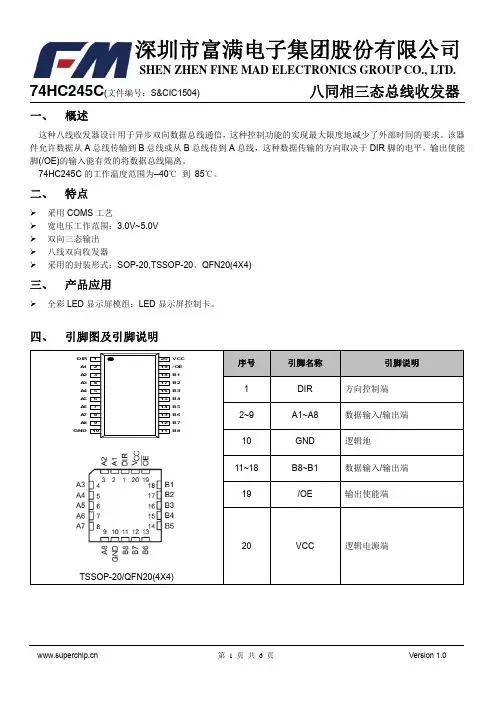
74HC245C(文件编号:S&CIC1504)八同相三态总线收发器一、概述这种八线收发器设计用于异步双向数据总线通信,这种控制功能的实现最大限度地减少了外部时间的要求。
该器件允许数据从A总线传输到B总线或从B总线传到A总线,这种数据传输的方向取决于DIR脚的电平。
输出使能脚(/OE)的输入能有效的将数据总线隔离。
74HC245C的工作温度范围为–40℃到85℃。
二、特点采用COMS工艺宽电压工作范围:3.0V~5.0V双向三态输出八线双向收发器采用的封装形式:SOP-20,TSSOP-20、QFN20(4X4)74HC245C(文件编号:S&CIC1504)八同相三态总线收发器五、绝对最大额定值74HC245C(文件编号:S&CIC1504)八同相三态总线收发器七、交流特性(VDD=5V Tamb=25℃)八、电气特性操作特性(TA=25℃)74HC245C(文件编号:九、参数测量信息3、波形之间的相位关系是被任意选择的,所有输入脉冲是由具有以下特点的信号发生器提供:PRR≤1MHz,Z O=50Ω,t r=6ns,t f=6ns.4、每一次输入数据的改变测量一次输出。
5、t PLZ和t PHZ与t dis是一样的。
6、t PZL和t PZH与t en是一样的。
7、t PLH和t PHL与t pd是一样的。
74HC245C(文件编号:S&CIC1504)八同相三态总线收发器十、封装信息TSSOP-20符号最小值典型值最大值A-- 1.10 1.15A10.02--0.08A20.95 1.00 1.05A30.380.430.48b0.170.220.25c0.100.150.20D 6.40 6.50 6.60E 6.30 6.40 6.50E1 4.30 4.40 4.50e0.65BSCL0.570.620.67L1 1.05BSCθ0°3°6°74HC245C(文件编号:S&CIC1504)八同相三态总线收发器。

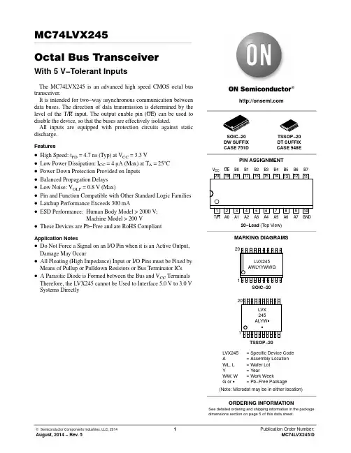
MC74LVX245Octal Bus TransceiverWith 5 V−Tolerant InputsThe MC74LVX245 is an advanced high speed CMOS octal bus transceiver.It is intended for two−way asynchronous communication between data buses. The direction of data transmission is determined by the level of the T/R input. The output enable pin (OE) can be used to disable the device, so that the buses are effectively isolated.All inputs are equipped with protection circuits against static discharge.Features•High Speed: t PD = 4.7 ns (Typ) at V CC = 3.3 V•Low Power Dissipation: I CC = 4 m A (Max) at T A = 25°C •Power Down Protection Provided on Inputs •Balanced Propagation Delays •Low Noise: V OLP = 0.8 V (Max)•Pin and Function Compatible with Other Standard Logic Families •Latchup Performance Exceeds 300 mA•ESD Performance:Human Body Model > 2000 V;Machine Model > 200 V•These Devices are Pb−Free and are RoHS CompliantApplication Notes•Do Not Force a Signal on an I/O Pin when it is an Active Output,Damage May Occur•All Floating (High Impedance) Input or I/O Pins must be Fixed by Means of Pullup or Pulldown Resistors or Bus Terminator ICs •A Parasitic Diode is Formed between the Bus and V CC Terminals Therefore, the LVX245 cannot be Used to Interface 5.0 V to 3.0 VSystems DirectlySee detailed ordering and shipping information in the package dimensions section on page 5 of this data sheet.ORDERING INFORMATION120MARKING DIAGRAMSSOIC−20DW SUFFIX CASE 751DTSSOP−20DT SUFFIX CASE 948ELVX245= Specific Device Code A = Assembly Location WL, L = Wafer Lot Y= YearWW, W = Work WeekG or G= Pb−Free Package(Note: Microdot may be in either location)LVX 245ALYW G GSOIC−20TSSOP−20PIN ASSIGNMENT20−Lead (Top View)192018171615142134567V CC 1381291110OE B0B1B2B3B4B5B6B7T/R A0A1A2A3A4A5A6A7GNDB0OE 19T/R 1A0B1A1B2A2B3A3B4A4B5A5B6A6B7A7Figure 1. Logic DiagramTable 1. PIN NAMESPins FunctionOE T/R A0−A7Bo−B7Output Enable Input Transmit/Receive InputSide A 3−State Inputs or 3−State Outputs Side B 3−State Inputs or 3−State OutputsINPUTS OPERATING MODE Non−Inverting OE T/R L L B Data to A Bus L H A Data to B Bus HXZH = High Voltage Level; L = Low Voltage Level; Z = High Impedance State;X = High or Low Voltage Level and Transitions are Acceptable; For I CC reasons, Do Not Float InputsMAXIMUM RATINGSSymbol Parameter Value Unit V CC DC Supply Voltage–0.5 to +7.0V V in DC Input Voltage (T/R, OE)–0.5 to +7.0V V I/O DC Output Voltage–0.5 to V CC +0.5VI IK Input Diode Current−20mAI OK Output Diode Current±20mAI out DC Output Current, per Pin±25mAI CC DC Supply Current, V CC and GND Pins±75mAP D Power Dissipation180mW T stg Storage Temperature–65 to +150°C Stresses exceeding those listed in the Maximum Ratings table may damage the device. If any of these limits are exceeded, device functionality should not be assumed, damage may occur and reliability may be affected.RECOMMENDED OPERATING CONDITIONSSymbol Parameter Min Max Unit V CC DC Supply Voltage 2.0 3.6V V in DC Input Voltage (T/R, OE)0 5.5V V I/O DC Output Voltage0V CC V T A Operating Temperature, All Package Types−40+85°CD t/D V Input Rise and Fall Time0100ns/V Functional operation above the stresses listed in the Recommended Operating Ranges is not implied. Extended exposure to stresses beyond the Recommended Operating Ranges limits may affect device reliability.DC ELECTRICAL CHARACTERISTICSSymbol Parameter Test Conditions V CCVT A = 25°C T A = −40 to 85°CUnit Min Typ Max Min MaxV IH High−Level Input Voltage 2.03.03.61.52.02.41.52.02.4VV IL Low−Level Input Voltage 2.03.03.60.50.80.80.50.80.8VV OH High−Level Output Voltage(V in = V IH or V IL)I OH = −50 m AI OH = −50 m AI OH = −4 mA2.03.03.01.92.92.582.03.01.92.92.48VV OL Low−Level Output Voltage(V in = V IH or V IL)I OL = 50 m AI OL = 50 m AI OL = 4 mA2.03.03.00.00.00.10.10.360.10.10.44VI in Input Leakage Current V in = 5.5 V or GND(T/R, OE)3.6±0.1±1.0m AI OZ Maximum 3−State Leakage Current V in = V IL or V IHV out = V CC or GND 3.6±0.25±2.5m AI CC Quiescent Supply Current V in = V CC or GND 3.6 4.040.0m A Product parametric performance is indicated in the Electrical Characteristics for the listed test conditions, unless otherwise noted. Product performance may not be indicated by the Electrical Characteristics if operated under different conditions.AC ELECTRICAL CHARACTERISTICS (Input t r = t f= 3.0 ns)Symbol Parameter Test ConditionsT A = 25°C T A = −40 to 85°CUnit Min Typ Max Min Maxt PLH, t PHL Propagation DelayInput to OutputV CC = 2.7 V C L = 15 pFC L = 50 pF6.18.610.714.21.01.013.517.0nsV CC = 3.3 ± 0.3 V C L = 15 pFC L = 50 pF4.77.26.610.11.01.08.011.5t PZL, t PZH Output Enable Time toHigh and Low LevelV CC = 2.7 V C L = 15 pFR L = 1 k W C L = 50 pF9.011.516.920.41.01.020.524.0nsV CC = 3.3 ± 0.3 V C L = 15 pFR L = 1 k W C L = 50 pF7.19.611.014.51.01.013.016.5t PLZ, t PHZ Output Disable Time FromHigh and Low LevelV CC = 2.7 V C L = 50 pFR L = 1 k W11.518.0 1.021.0nsV CC = 3.3 ± 0.3 V C L = 50 pFR L = 1 k W9.612.8 1.014.5t OSHL t OSLH Output−to−Output Skew(Note 1)V CC = 2.7 V C L = 50 pFV CC = 3.3 ±0.3 V C L = 50 pF1.51.51.51.5ns1.Skew is defined as the absolute value of the difference between the actual propagation delay for any two separate outputs of the same device.The specification applies to any outputs switching in the same direction, either HIGH−to−LOW (t OSHL) or LOW−to−HIGH (t OSLH); parameter guaranteed by design.CAPACITIVE CHARACTERISTICSSymbol ParameterT A = 25°C T A = −40 to 85°CUnit Min Typ Max Min MaxC in Input Capacitance (T/R, OE)41010pFC I/O Maximum 3−State I/O Capacitance8pFC PD Power Dissipation Capacitance (Note 2)21pF2.C PD is defined as the value of the internal equivalent capacitance which is calculated from the operating current consumption without load.Average operating current can be obtained by the equation: I CC(OPR) = C PD V CC f in + I CC/8 (per bit). C PD is used to determine the no−load dynamic power consumption; P D = C PD V CC2 f in + I CC V CC.NOISE CHARACTERISTICS (Input t r = t f = 3.0ns, C L = 50pF, V CC = 3.3V, Measured in SOIC Package)Symbol CharacteristicT A = 25°CUnit Typ MaxV OLP Quiet Output Maximum Dynamic V OL0.50.8V V OLV Quiet Output Minimum Dynamic V OL−0.5−0.8V V IHD Minimum High Level Dynamic Input Voltage 2.0V V ILD Maximum Low Level Dynamic Input Voltage0.8VFigure 2. Figure 3.V CCGNDSWITCHING WAVEFORMSOEA or BA or BV CCGND HIGHIMPEDANCE V OL +0.3V V OH -0.3V HIGHIMPEDANCEV CC GNDT/R*Includes all probe and jig capacitance C L *TEST POINT *Includes all probe and jig capacitanceTEST POINT CONNECT TO V CC WHEN TESTING t PLZ AND t PZL .CONNECT TO GND WHEN TESTING t PHZ AND t PZH .TEST CIRCUITSFigure 4. Propagation Delay Test Circuit Figure 5. 3−State Test CircuitORDERING INFORMATIONDevicePackage Shipping †MC74LVX245DWR2G SOIC−20(Pb−Free)1000 / Tape & Reel MC74LVX245DTR2GTSSOP−20(Pb−Free)2500 / Tape & Reel†For information on tape and reel specifications, including part orientation and tape sizes, please refer to our Tape and Reel Packaging Specifications Brochure, BRD8011/D.CASE 948E−02ISSUE CDIM A MIN MAX MIN MAX INCHES 6.600.260MILLIMETERS B 4.30 4.500.1690.177C 1.200.047D 0.050.150.0020.006F 0.500.750.0200.030G 0.65 BSC 0.026 BSC H 0.270.370.0110.015J 0.090.200.0040.008J10.090.160.0040.006K 0.190.300.0070.012K10.190.250.0070.010L 6.40 BSC 0.252 BSCM0 8 0 8 ____NOTES:1.DIMENSIONING AND TOLERANCING PER ANSI Y14.5M, 1982.2.CONTROLLING DIMENSION:MILLIMETER.3.DIMENSION A DOES NOT INCLUDE MOLD FLASH, PROTRUSIONS OR GATE BURRS. MOLD FLASH OR GATE BURRS SHALL NOT EXCEED 0.15 (0.006) PER SIDE.4.DIMENSION B DOES NOT INCLUDE INTERLEAD FLASH OR PROTRUSION.INTERLEAD FLASH OR PROTRUSIONSHALL NOT EXCEED 0.25 (0.010) PER SIDE.5.DIMENSION K DOES NOT INCLUDE DAMBAR PROTRUSION. ALLOWABLE DAMBAR PROTRUSION SHALL BE 0.08(0.003) TOTAL IN EXCESS OF THE K DIMENSION AT MAXIMUM MATERIAL CONDITION.6.TERMINAL NUMBERS ARE SHOWN FOR REFERENCE ONLY .7.DIMENSION A AND B ARE TO BE DETERMINED AT DATUM PLANE −W−.DETAIL E6.400.252------16X0.360.65PITCHSOLDERING FOOTPRINT**For additional information on our Pb−Free strategy and soldering details, please download the ON Semiconductor Soldering and Mounting Techniques Reference Manual, SOLDERRM/D.CASE 751D−05ISSUE GM0.25SA SBTDIM MIN MAXMILLIMETERSA 2.35 2.65A10.100.25B0.350.49C0.230.32D12.6512.95E7.407.60e 1.27 BSCH10.0510.55h0.250.75L0.500.90q0 7NOTES:1.DIMENSIONS ARE IN MILLIMETERS.2.INTERPRET DIMENSIONS AND TOLERANCESPER ASME Y14.5M, 1994.3.DIMENSIONS D AND E DO NOT INCLUDE MOLDPROTRUSION.4.MAXIMUM MOLD PROTRUSION 0.15 PER SIDE.5.DIMENSION B DOES NOT INCLUDE DAMBARPROTRUSION. ALLOWABLE PROTRUSIONSHALL BE 0.13 TOTAL IN EXCESS OF BDIMENSION AT MAXIMUM MATERIALCONDITION.__ON Semiconductor and the are registered trademarks of Semiconductor Components Industries, LLC (SCILLC) or its subsidiaries in the United States and/or other countries.SCILLC owns the rights to a number of patents, trademarks, copyrights, trade secrets, and other intellectual property. A listing of SCILLC’s product/patent coverage may be accessed at /site/pdf/Patent−Marking.pdf. SCILLC reserves the right to make changes without further notice to any products herein. SCILLC makes no warranty, representation or guarantee regarding the suitability of its products for any particular purpose, nor does SCILLC assume any liability arising out of the application or use of any product or circuit, and specifically disclaims any and all liability, including without limitation special, consequential or incidental damages. “Typical” parameters which may be provided in SCILLC data sheets and/or specifications can and do vary in different applications and actual performance may vary over time. All operating parameters, including “Typicals” must be validated for each customer application by customer’s technical experts. SCILLC does not convey any license under its patent rights nor the rights of others. SCILLC products are not designed, intended, or authorized for use as components in systems intended for surgical implant into the body, or other applications intended to support or sustain life, or for any other application in which the failure of the SCILLC product could create a situation where personal injury or death may occur. Should Buyer purchase or use SCILLC products for any such unintended or unauthorized application, Buyer shall indemnify and hold SCILLC and its officers, employees, subsidiaries, affiliates, and distributors harmless against all claims, costs, damages, and expenses, and reasonable attorney fees arising out of, directly or indirectly, any claim of personal injury or death associated with such unintended or unauthorized use, even if such claim alleges that SCILLC was negligent regarding the design or manufacture of the part. SCILLC is an Equal Opportunity/Affirmative Action Employer. This literature is subject to all applicable copyright laws and is not for resale in any manner.PUBLICATION ORDERING INFORMATIONMouser ElectronicsAuthorized DistributorClick to View Pricing, Inventory, Delivery & Lifecycle Information:O N Semiconductor:MC74LVX245MELG MC74LVX245MG MC74LVX245DTR2MC74LVX245DTR2G MC74LVX245DWR2 MC74LVX245DWR2G。
八路总线收发器具有热插入和总线保持功能补充
Diodes公司逻辑产品组合
Diodes 公司推出能够在数据总线之间实现异步通信的74LVT245BB 八路收发器,其控制引脚确定数据流方向,同时禁用三态输出,允许总路线完全隔离。
数据总线以往主要用于计算机应用,现在电视机、机顶盒、基站和多种其它数据通信设备中广泛应用,为各种收发器电路提供了广阔的市场。
74LVT245BB器件为数据总线之间的正常异步通信提供了部分掉电功能,从而禁用输出并且在设备掉电时防止损坏电流回流。
这款器件还通过在上电期间保持三态输出来耐受热插入。
施密特触发输入还包括总线保持功能,因而未使用的输入无需电阻器。
结合优于500mA的闭锁免疫能力,这些收发器可推动实现广泛的设计,能够在计算机服务器和蜂窝电话基站等应用中进行热插拨而无需关闭设备。
74LVT245BB器件指定在2.7V至3.6V供电电压范围运作,可以在3.3V或5V驱动输入,允许混合逻辑电压应用。
其输出可以吸收64mA或提供32mA电流,并且在强制达到5.5V时具有《125μA的泄漏电流。
74LVT245BB器件的传播时间为2.7ns (典型),具有适用于大型总线架构的驱动能力,以及掉电以避免载入数据总线的功能,在功率性能比、可靠性和成本方面带来优势。
74LVXC3245MTCX原理1.概述本文档将介绍74LV XC3245M TC X芯片的原理、功能及使用方法。
该芯片是一种高集成度、高速驱动能力的双向总线转换器。
它具有诸多特点和应用场景,本文将详细讲解。
2. 74LVXC3245MTC X芯片的特点-双向总线转换器,能够实现逻辑电平的双向转换-低功耗设计,适用于电池供电系统-高速传输,最大传输速率可达100MH z-支持5V和3.3V之间的电平转换3.功能描述74LV XC3245MT CX芯片具有以下主要功能:3.1电平转换该芯片可以实现5V和3.3V之间的双向电平转换。
通过引脚的设置,可以将5V逻辑电平转换为3.3V逻辑电平,或者将3.3V逻辑电平转换为5V逻辑电平。
3.2双向传输该芯片支持双向数据传输,可以在两个总线之间进行数据的双向传输。
它能够实现将数据从一侧总线传输到另一侧总线,同时保持两侧总线的输入输出状态。
3.3高速传输74LV XC3245MT CX芯片具有高速传输的能力,最大传输速率可达100M Hz。
这使得它适用于高速数据传输的场景,如计算机总线、存储器接口等。
4.使用方法使用74LV XC3245MTC X芯片进行电平转换和双向传输的方法如下:1.设置引脚电平:根据需求,将DI R引脚设置为高电平或低电平,以确定数据传输的方向。
2.连接总线:将要进行转换的两个总线分别连接到A端和B端。
3.数据传输:通过控制DI R引脚的电平,实现双向数据的传输。
使用74LV XC3245MTC X芯片时需要注意以下事项:-确保供电电压符合芯片的规格要求,以避免损坏芯片或降低性能。
-使用正确的引脚连接方式,确保总线连接正确无误。
-在高速传输时,要保持信号线的稳定性,减少信号干扰。
5.应用场景74LV XC3245MT CX芯片广泛应用于以下场景:1.计算机总线:用于连接不同电平的总线,实现数据的双向传输和电平转换。
2.存储器接口:用于连接处理器和存储器,实现高速数据的传输。
74hc245 的作用是什么74hc245 应用原理是什么
大家都知道,74hc245CMOS 高速收发器,那幺它有什幺作用你知道吗,它在电路中的应用原理呢?本文讲解的是74hc245 的作用是什幺,以及
74hc245 应用原理是什幺。
74hc245
74hc245 是一种兼容TTL 器件引脚的高速CMOS 总线收发器(bus transceiver),典型的CMOS 型三态缓冲门电路,八路信号收发器。
由于单片机或CPU 的数据/地址/控制总线端口都有一定的负载能力,如果负载超过其负载能力,一般应加驱动器。
主要应用于大屏显示,以及其它的消费类电子产品中增加驱动。
特征
输出驱动能力:15 个LTSTL 负载
输出直接与CMOS、NMOS 和TTL 接口。
IMPORTANT NOTICETexas Instruments Incorporated and its subsidiaries (TI) reserve the right to make corrections, modifications, enhancements, improvements, and other changes to its products and services at any time and to discontinue any product or service without notice. Customers should obtain the latest relevant information before placing orders and should verify that such information is current and complete. All products are sold subject to TI’s terms and conditions of sale supplied at the time of order acknowledgment.TI warrants performance of its hardware products to the specifications applicable at the time of sale in accordance with TI’s standard warranty. Testing and other quality control techniques are used to the extent TI deems necessary to support this warranty. Except where mandated by government requirements, testing of all parameters of each product is not necessarily performed.TI assumes no liability for applications assistance or customer product design. Customers are responsible for their products and applications using TI components. To minimize the risks associated with customer products and applications, customers should provide adequate design and operating safeguards.TI does not warrant or represent that any license, either express or implied, is granted under any TI patent right, copyright, mask work right, or other TI intellectual property right relating to any combination, machine, or process in which TI products or services are used. Information published by TI regarding third–party products or services does not constitute a license from TI to use such products or services or a warranty or endorsement thereof. Use of such information may require a license from a third party under the patents or other intellectual property of the third party, or a license from TI under the patents or other intellectual property of TI.Reproduction of information in TI data books or data sheets is permissible only if reproduction is without alteration and is accompanied by all associated warranties, conditions, limitations, and notices. Reproduction of this information with alteration is an unfair and deceptive business practice. TI is not responsible or liable for such altered documentation.Resale of TI products or services with statements different from or beyond the parameters stated by TI for that product or service voids all express and any implied warranties for the associated TI product or service and is an unfair and deceptive business practice. TI is not responsible or liable for any such statements.Mailing Address:Texas InstrumentsPost Office Box 655303Dallas, Texas 75265Copyright 2002, Texas Instruments Incorporated。
基于STM32的报警显示系统设计张文新【摘要】Introduces a kind of Warning and Display System, in this system, the chip that STM32F103VE is the operation core, FPGA is the control component of timer and logic, and AD9985A is the analog to digital converter. The hardware design of this systemˊs is simple, and relia-bility is high. It can be flexibly applied to all kinds of industrial data acquisition system which requires the human-computer interaction using environment, and has a wide application prospect.%介绍一种以STM32F103VE芯片为主控制器,以FPGA芯片为时序逻辑控制器,以AD9985A芯片为模数转换器的实时报警显示系统。
该系统硬件架构简单,可靠性高,可灵活应用于各种需要人机交互使用环境的工业级数据采集系统中,应用前景广泛。
【期刊名称】《现代计算机(专业版)》【年(卷),期】2016(000)020【总页数】6页(P85-90)【关键词】报警显示系统;STM32F103VE;AD9985A;人机交互【作者】张文新【作者单位】广州海格通信集团股份有限公司,广州 510663【正文语种】中文介绍一种以STM32F103VE芯片为主控制器,以FPGA芯片为时序逻辑控制器,以AD9985A芯片为模数转换器的实时报警显示系统。
该系统硬件架构简单,可靠性高,可灵活应用于各种需要人机交互使用环境的工业级数据采集系统中,应用前景广泛。
74HC245详细中文资料74HC245是一款高速CMOS器件,74HC2 45引脚兼容低功耗肖特基TTL(LSTTL)系列。
74HC245译码器可接受3位二进制加权地址输入(A0, A1和A2),并当使能时,提供8个互斥的低有效输出(Y0至Y7)。
74HC245特有3个使能输入端:两个低有效(E1和E2)和一个高有效(E3)。
除非E1和E2置低且E3置高,否则74HC138将保持所有输出为高。
利用这种复合使能特性,仅需4片74HC 245芯片和1个反相器,即可轻松实现并行扩展,组合成为一个1-32(5线到3 2线)译码器。
任选一个低有效使能输入端作为数据输入,而把其余的使能输入端作为选通端,则74HC245亦可充当一个8输出多路分配器,未使用的使能输入端必须保持绑定在各自合适的高有效或低有效状态。
74HC245与74HC 238逻辑功能一致,只不过74HC138为反相输出。
功能CD74HC245 ,CD74HC238和CD74HCT245,CD74HCT238是高速硅栅CMOS解码器,适合内存地址解码或数据路由应用。
74HC245作用原理于高性能的存贮译码或要求传输延迟时间短的数据传输系统,在高性能存贮器系统中,用这种译码器可以提高译码系统的效率。
将快速赋能电路用于高速存贮器时,译码器的延迟时间和存贮器的赋能时间通常小于存贮器的典型存取时间,这就是说由肖特基钳位的系统译码器所引起的有效系统延迟可以忽略不计。
HC138 按照三位二进制输入码和赋能输入条件,从8 个输出端中译出一个低电平输出。
两个低电平有效的赋能输入端和一个高电平有效的赋能输入端减少了扩展所需要的外接门或倒相器,扩展成24 线译码器不需外接门;扩展成32 线译码器,只需要接一个外接倒相器。
在解调器应用中,赋能输入端可用作数据输入端。
特性复合使能输入,轻松实现扩展兼容JEDEC标准no.7A 存储器芯片译码选择的理想选择低有效互斥输出ESD保护HBM EIA/JESD22-A114-C超过20 00 V MM EIA/JESD22-A115-A超过200 V 温度范围-40~+85 ℃-40~+12 5 ℃多路分配功能 74HC245是一款高速CMOS器件,74HC245引脚兼容低功耗肖特基TTL(LSTTL)系列。
LED 显示屏中常用的芯片说明及原理Led中常见的芯片有:74HC595列驱动,74HC138译码驱动,74HC245信号放大,74HC4953行扫描等。
1、74HC59574HC595是硅结构的CMOS器件,兼容低电压TTL电路,遵守JEDEC标准。
74HC595是具有8位移位寄存器和一个存储器,三态输出功能。
移位寄存器和存储器是分别的时钟。
数据在SHcp(移位寄存器时钟输入)的上升沿输入到移位寄存器中,在STcp(存储器时钟输入)的上升沿输入到存储寄存器中去。
如果两个时钟连在一起,则移位寄存器总是比存储寄存器早一个脉冲。
移位寄存器有一个串行移位输入(Ds),和一个串行输出(Q7’),和一个异步的低电平复位,存储寄存器有一个并行8位的,具备三态的总线输出,当使能OE时(为低电平),存储寄存器的数据输出到总线。
8位串行输入/输出或者并行输出移位寄存器,具有高阻关断状态。
三态。
将串行输入的8位数字,转变为并行输出的8位数字,例如控制一个8位数码管,将不会有闪烁。
2特点8位串行输入 /8位串行或并行输出存储状态寄存器,三种状态输出寄存器(三态输出:就是具有高电平、低电平和高阻抗三种输出状态的门电路。
)可以直接清除 100MHz的移位频率特点8位串行输入/8位串行或并行输出存储状态寄存器,三种状态输出寄存器(三态输出:就是具有高电平、低电平和高阻抗三种输出状态的门电路。
)可以直接清除100MHz的移位频率3输出能力并行输出,总线驱动;串行输出;标准中等规模集成电路595移位寄存器有一个串行移位输入(Ds),和一个串行输出(Q7’),和一个异步的低电平复位,存储寄存器有一个并行8位的,具备三态的总线输出,当使能OE时(为低电平),存储寄存器的数据输出到总线。
参考数据Cpd决定动态的能耗,Pd=Cpd×VCC×f1+∑(CL×VCC^2×f0)F1=输入频率,CL=输出电容f0=输出频率(MHz)Vcc=电源电压4、引脚说明符号引脚描述Q0…Q7 8位并行数据输出,其中Q0为第15脚GND 第8脚地Q7’第9脚串行数据输出MR 第10脚主复位(低电平)SHCP 第11脚移位寄存器时钟输入STCP 第12脚存储寄存器时钟输入OE 第13脚输出有效(低电平)DS 第14脚串行数据输入VCC 第16脚电源2、74HC138 芯片74HC138是一款高速CMOS器件,74HC138引脚兼容低功耗肖特基TTL(LSTTL)系列。
74HC245详细中文资料74HC245是一款高速CMOS器件,74HC2 45引脚兼容低功耗肖特基TTL (LSTTL)系列。
74HC245译码器可接受3位二进制加权地址输入(A0, A1和A2),并当使能时,提供8个互斥的低有效输出(Y0至Y7)o74HC245特有3个使能输入端:两个低有效(E1和E2)和一个高有效(E3)。
除非E1和E2置低且E3置高,否则74HC138将保持所有输出为高。
利用这种复合使能特性,仅需4片74HC 245芯片和1个反相器,即可轻松实现并行扩展,组合成为一个1-32(5线到3 2线)译码器。
任选一个低有效使能输入端作为数据输入,而把其余的使能输入端作为选通端,则74HC245亦可充当一个8输出多路分配器,未使用的使能输入端必须保持绑定在各自合适的高有效或低有效状态。
74HC245与74HC 238逻辑功能一致,只不过74HC138为反相输出。
功能CD74HC245,CD74HC238 和CD74HCT245,CD74HCT238 是高速硅栅CMOS解码器,适合内存地址解码或数据路由应用。
74HC245作用原理于高性能的存贮译码或要求传输延迟时间短的数据传输系统,在高性能存贮器系统中,用这种译码器可以提高译码系统的效率。
将快速赋能电路用于高速存贮器时, 译码器的延迟时间和存贮器的赋能时间通常小于存贮器的典型存取时间,这就是说由肖特基钳位的系统译码器所引起的有效系统延迟可以忽略不计。
HC138按照三位二进制输入码和赋能输入条件,从8个输出端中译出一个低电平输出。
两个低电平有效的赋能输入端和一个高电平有效的赋能输入端减少了扩展所需要的外接门或倒相器,扩展成24线译码器不需外接门;扩展成32线译码器,只需要接一个外接倒相器。
在解调器应用中,赋能输入端可用作数据输入端。
特性仅供学习与参考复合使能输入,轻松实现扩展兼容JEDEC标准no.7A存储器芯片译码选择的理想选择低有效互斥输出ESD保护HBM EIA/JESD22-A114-C超过20 00 V MM EIA/JESD22-A115-A超过200 V 温度范围-40〜+85 ℃ -40〜+12 5 ℃多路分配功能74HC245是一款高速CMOS器件,74HC245引脚兼容低功耗肖特基TTL (LSTTL)系歹列。
元器件交易网IMPORTANT NOTICETexas Instruments and its subsidiaries (TI) reserve the right to make changes to their products or to discontinueany product or service without notice, and advise customers to obtain the latest version of relevant informationto verify, before placing orders, that information being relied on is current and complete. All products are soldsubject to the terms and conditions of sale supplied at the time of order acknowledgement, including thosepertaining to warranty, patent infringement, and limitation of liability.TI warrants performance of its semiconductor products to the specifications applicable at the time of sale inaccordance with TI’s standard warranty. Testing and other quality control techniques are utilized to the extentTI deems necessary to support this warranty. Specific testing of all parameters of each device is not necessarilyperformed, except those mandated by government requirements.CERTAIN APPLICATIONS USING SEMICONDUCTOR PRODUCTS MAY INVOLVE POTENTIAL RISKS OFDEATH, PERSONAL INJURY, OR SEVERE PROPERTY OR ENVIRONMENTAL DAMAGE (“CRITICALAPPLICATIONS”). TI SEMICONDUCTOR PRODUCTS ARE NOT DESIGNED, AUTHORIZED, ORWARRANTED TO BE SUITABLE FOR USE IN LIFE-SUPPORT DEVICES OR SYSTEMS OR OTHERCRITICAL APPLICATIONS. INCLUSION OF TI PRODUCTS IN SUCH APPLICATIONS IS UNDERSTOOD TOBE FULLY AT THE CUSTOMER’S RISK.In order to minimize risks associated with the customer’s applications, adequate design and operatingsafeguards must be provided by the customer to minimize inherent or procedural hazards.TI assumes no liability for applications assistance or customer product design. TI does not warrant or representthat any license, either express or implied, is granted under any patent right, copyright, mask work right, or otherintellectual property right of TI covering or relating to any combination, machine, or process in which suchsemiconductor products or services might be or are used. TI’s publication of information regarding any thirdparty’s products or services does not constitute TI’s approval, warranty or endorsement thereof.Copyright © 1998, Texas Instruments Incorporated。
用8位总线控制、应用广泛的12位通用电路的功能以测量或控制为目的的模拟电路需要12位分辨率。
本电路用8位总线控制得到广泛应用的12位D-A转换器DAC80,这是一种通用性极强的电路。
可很方便地用跨接线选择输出极性和输出电压范围等。
电路工作原理8位微型计算机的数据是用8位并行输出的,除串行输入的D-A 转换器外,一般必须把数据分成两组输入、并加以调整。
要求数据锁存器应为16位。
先把D7~D4这四位数据锁存在低位字节,用下一个时钟脉冲同时把已锁的4位数据和高位字节送人12位D-A转换器。
DAC80-CB1-V是地进制输入的电压输出D-A转换器,其基准电压为6.3V,接在REF-IN端,也可把跨接线J1去掉,从外部输入。
当需要使用多个DAC,使电路具有跟踪特性时,多采用这种方法。
BP为双极置偏端子,若输出双极性电压,可将跨接线J2短路,用内部的6.3K电阻使1MA的电流流过。
用接在正负RCC的可变电阻进行增益调整和调零,如电源不稳,应采用齐纳二极管使其稳定,然后再接到VR1和VR2上。
跨接线J3和J4用来选择输出幅度,J3短路可输出20VP-P电压,J4短路。
可输出10VP-P电压,所以在设计电路底板时应考虑设置跨接线插孔,本电路图为双极性输出、电压为正负10V的接线状态。
组装注意事项12位数据输入线要尽量短,并用外层接地的屏蔽线,以免逻辑信号与模拟电路耦合。
因为DAC80的引线1~12均为逻辑输入,所以在IC下面布置了地线。
应特别注意,求和连接的引线20和BP置偏的引线17均为微弱电平引线,为了避免与其它引线耦合,要缩短走线长度,并且必须用外层接地的屏蔽线。
为了提高输出电压0V的精度,模拟量和数字的接地要明确分开,两部分的地线可在D-A转换器附近相接,或在电源地线端子处相接。
关于D-A转换器:输入数据一变,由于同步,内部电流也要改变,所以在IC附近加了电源旁路电容C2、C3。
74HC245引脚图应用电路与中文资料74HC244 是一款常见的驱动信号芯片,常用于各种单片机mcu系统中,单片机io口输出的电流很小而244芯片就是用来放大电流,他是具有三态输出的八路缓冲器和线路驱动器,他与74HC245的唯一区别是74HC244是单向的,数据只能从A端流向Y 端,而74HC245则是双向的。
他们的驱动能力相同。
74hc244的pdf资料下74HC244也常常用于隔离,比如单片机和并口等设备直连理论上可以直接用单片机的几根I/O口接并口线,但如果电路板没做好,可能会连带把计算机并口烧坏,所以要加个74HC244芯片隔离一下74HC244 是CMOS电路,74ls244 是双极晶体管型电路,二者的特性差别很大,LS器件是淘汰型,尽量不要选用。
74HC240,74HC241,74HC244为同一系列的产品,他们的区别很小在引脚及其功能方面下面的中文资料中都有详细的说明.74hc244实物图74hc244管脚图下面介绍74hc244的功能:74HC244芯片内部共有两个四位三态缓冲器,使用时可分别以1C和2G作为它们的选通工作信号。
当1C和2G都为低电平时,输出端Y和输入端A状态相同;当1G和2G都为高电平时,输出呈高阻态。
八同相三态缓冲器/线驱动器74HC233芯片功能如果输入的数据可以保持比较长的时间(比如键盘),简单输入接口扩展通常使用的典型芯片为74HC244,由该芯片可构成三态数据缓冲器。
74HC244芯片引脚排列如图1所示。
74HC244芯片内部共有两个四位三态缓冲器,使用时分别以1C和2G作为它们的选通工作信号。
当1/0E和2/0E都为低电平时,输出端Y和输入端A状态相同;当1/0E和2/0E 都为高电平时,输出成高阻态dip封装的74hc244引脚图贴片74hc244引脚图74hc244封装图74hc244真值表74hc244及74hc241 74hc240功能表缓冲并行端口电路74hc244应用电路74hc244电流最大值74hc244电压温度等操作条件。
8线总线收发器SN74LVCC3245的原理及应用
在新一代电子产品设计与应用中,低功耗和高速度已经成为数字电路设计的发展趋势。
但是众所再知,芯片的功耗与频率成正比关系,这两个看似不可调和的矛盾,最终导致了各种低压数字器件的出现。
如TI公司的TMS320F2812就采用了核心1.8V和外围电路由3.3V供电的架构,但这也同时带来了新的问题,就是大多数外围数字芯片仍为TTL或CMOS逻辑电平,当把微处理器I/O电压移植到较低的节点,而外设仍留在电压较高的节点时,经常会出现微处理器与外设I/O之间电压不匹配的现象。
针对上述问题,德州仪器(TI)推出了AVC及LVC等多款新型双电源电平转换收发器,从而为运行于不同电压节点上的接口设备提供了理想的选择。
这些转换产品能够在1.5V、1.8V、2.5V、3.3V与5V电压节点之间进行灵活的双向电平转换,因此非常适用于便携式消费类电子产品、网络、数据通信及计算应用领域。
TI的新型双电源电平转换器件能够在保持信号完整性及速度不变的情况下,在接口电压完全不同的两个设备之间进行通信。
此外,该系列器件还提供全面的可配置性,如果采用AVC技术,则每条轨可从1.4V配置为3.6V,而采用LVC技术则可从1.65V配置为5.5V。
本文介绍带有三态输出且输出电压可调的8线总线双向电平转换器SN74LVCC3245的原理及应用。
1 SN74LVCC3245简介
SN74LVCC3245是8位正逻辑总线收发器,它有两个独立供电电源轨。
其中B口被用来跟踪Vccb电压,可以接收的电压范围为3V到5.5V,与此相对应的A口则用来跟踪VCCA电压,可以接收的电压范围为2.5V到3.6V。
这种结构允许数字逻辑从一个供电电压为3.3V的系统环境转换到一个供电电压为5.5V的系统环境,反之亦然。
SN74LVCC3245可以应用于数字总线间的异步通讯,完全数据从A总线到B总线或B总线到A 总线的数字传递,传递方向取决于方向控制引脚DIR上的逻辑电平。
输出允许引脚OE可以用来禁用器件,这样可对总线进行有效隔离。
这些控制电路(DIR,OE)是由VCCA供电的。
图1示出SN74LVCC3245的引脚排列。
SN74LVCC3245双向电平转换器具有如下主要特点:
·双向电压转换;
·A口输出电压范围为2.3V~3.6V;B口输出电压范围为3V~5.5V;
·控制输入信号VIH/VIL逻辑电平参数VCCA的电压
2 真值表和内部逻辑
表1是SN74LVCC3245的逻辑真值表,当OE和DIR均为低电平时,数据由B口传输到A口;当OE为低电平而DIR为高电平时,数据由A口传输到B口;如果OE为高电平,则器件将与外部总线隔离。
3 SN74LVCC3245在DSP中的应用
DSP以其强大的信号处理能力见长,但控制能力却明显不足。
因此,当设计控制口线较多的系统时,可采用双处理器的方法(即采用DSP加控制器力相对较强的普通52单片机)来构成整个系统,这样,DSP作为下位机发挥其运行能力强的优势来进行信号处理,并通过串口与上位机(单片机)通讯,接收其控制指令和设置参数,并将处理好的数据传输到52单片机,而单片机完成数据显示、打印等控制功能。
这样,在该系统中就会存在电平不匹配的问题。
如系统使用的DSP是TI公司的TMS320F2812,那么,其I/O电源是3.3V,但普通52单片机的数字逻辑电平为5V的CMOS电平,这就需要对两者通讯所用的串口信号线进行电平转换。
此外,SPI(serial peripheral interface)总线串口是由Motorola公司提出的一种同步串行外设接口,该接口通常也需要完成TxD和RxD这两根信号线的电平转换。
VHC245内部结构。