步进电机中英文对照外文翻译文献
- 格式:doc
- 大小:57.50 KB
- 文档页数:14
附录2:英文资料及其中文翻译Stepper motor is an electrical pulse will be converted into angular displacement of the implem enting agencies. Put it in simple language-speaking: When the stepper drive pulse signal to a r eceiver, it drives stepper motor rotation direction by setting a fixed point of view (and the ste p angle). You can control the number of pulses to control the amount of angular displacement, so as to achieve the purpose of accurate positioning; At the same time, you can by controllin g the pulse frequency to control the motor rotation speed and acceleration, so as to achieve th e purpose of speed.Stepper motor directly from the AC-DC power supply, and must use special equipment - stepp er motor drive. Stepper motor drive system performance, in addition to their own performance with the motor on the outside, but also to a large extent depend on the drive is good or bad.A typical stepper motor drive system is operated by the stepper motor controller, stepper mot or drives and stepper motor body is composed of three parts. Stepper motor controller stepper pulse and direction signal, each made of a pulse, stepper motor-driven stepper motor drives a rotor rotating step angle, that is, step-by-step further. High or low speed stepper motor, or spe ed, or deceleration, start or stop pulses are entirely dependent on whether the level or frequenc y. Decide the direction of the signal controller stepper motor clockwise or counterclockwise rot ation. Typically, the stepper motor drive circuit from the logic control, power driver circuit, pr otection circuit and power components. Stepper motor drive controller, once received from the direction of the signal and step pulse, the control circuit on a pre-determined way of the electr ical power-phase stepper motor excitation windings of the conduction or cut-off signal. Control circuit output signal power is low, can not provide the necessary stepping motor output powe r, the need for power amplifier, which is stepper motor driven power drive part. Power stepper motor drive circuit to control the input current winding to form a space for rotating magnetic field excitation, the rotor-driven movement. Protection circuit in the event of short circuit, ove rload, overheating, such as failure to stop the rapid drive and motor.Motor is usually for the permanent magnet rotor, when the current flows through the stator wi ndings, the stator windings produce a magnetic field vector. The magnetic field will lead to a rotor angle of rotation, making a pair of rotor and stator magnetic field direction of the magne tic field direction. When the stator rotating magnetic field vector from a different angle. Also as the rotor magnetic field to a point of view. An electrical pulse for each input, the motor r otation angle step. Its output and input of the angular displacement is proportional to the pulse s, with pulse frequency proportional to speed. Power to change the order of winding, the elect rical will be reversed. We can, therefore, control the pulse number, frequency and electrical po wer windings of each phase to control the order of rotation of stepper motor.Stepper motor types:Permanent magnet (PM). Magnetic generally two-phase stepper, torque and are smaller and gen erally stepping angle of 7.5 degrees or 15 degrees; put more wind for air-conditioning. Reactive (VR), the domestic general called BF, have a common three-phase reaction, step angl e of 1.5 degrees; also have five-phase reaction. Noise, no torque has been set at a large numb er of out.Hybrid (HB), common two-phase hybrid, five-phase hybrid, three-phase hybrid, four-phase hybri d, two-phase can be common with the four-phase drive, five-phase three-phase must be used w ith their drives;Two-phase, four-phase hybrid step angle is 1.8 degrees more than a small size, great distance, and low noise;Five-phase hybrid stepping motor is generally 0.72, the motor step angle small, high resolution, but the complexity of drive circuits, wiring problems, such as the 5-phase system of 10 lines. Three-phase hybrid stepping motor step angle of 1.2 degrees, but according to the use of 1.8 degrees, the three-phase hybrid stepping motor has a two-phase mixed than the five-phase hybr id more pole will help electric folder symmetric angle, it can be more than two-phase, five-ph ase high accuracy, the error even smaller, run more smoothly.Stepper motor to maintain torque: stepper motor power means no rotation, the stator locked rot or torque. It is a stepper motor, one of the most important parameters, usually in the low-spee d stepper motor torque at the time of close to maintain the torque. As the stepper motor outp ut torque increases with the speed of constant attenuation, the output power also increases with the speed of change, so as to maintain torque on the stepper motor to measure the parameter s of one of the most important. For example, when people say that the stepper motor 2N.m, i n the absence of special circumstances that means for maintaining the torque of the stepper m otor 2N.m.Precision stepper motors: stepper motor step angle accuracy of 3-5%, not cumulative.Start frequency of no-load: the stepper motor in case of no-load to the normal start of the pul se frequency, if the pulse frequency is higher than the value of motor does not start, possible to lose steps or blocking. In the case of the load, start frequency should be lower. If you wa nt to achieve high-speed rotation motor, pulse frequency should be to accelerate the process, th at is, the lower frequency to start, and then rose to a certain acceleration of the desired freque ncy (motor speed from low rise to high-speed).Step angle: that is to send a pulse, the electrical angle corresponding to rotation.Torque positioning: positioning torque stepper motor does not refer to the case of electricity, l ocked rotor torque stator.Operating frequency: step-by-step stepper motor can run without losing the highest frequency. Subdivision Drive: stepper motor drives the main aim is to weaken or eliminate low-frequency vibration of the stepper motor to improve the accuracy of the motor running. Reduce noise. I f the step angle is 1.8 °(full step) the two-phase hybrid stepping motor, if the breakdown of the breakdown of the number of drives for the 8, then the operation of the electrical pulse for each resolution of 0.072 °, the precision of motor can reach or close to 0.225 °, also depend s on the breakdown of the breakdown of the drive current control accuracy and other factors, the breakdown of the number of the more difficult the greater the precision of control.步进电机是一种将电脉冲转化为角位移的执行机构。
步进电机PLC控制技术中英文对照外文翻译文献中英文对照外文翻译文献(文档含英文原文和中文翻译)The shallow treads into the PLC control technique and development trend of electrical engineering1. Say all:Along with the micro-electronics technique and the calculator technical hair Exhibition, the programmable preface controller has an advance by leaps and bounds of hair Exhibition, its function has already outrun a logic control far and far, in proper order The scope of control, it has an effect to combine with calculator, can enter Go to imitate to control most, have along range correspondence function etc.. Have-The person is called it the modern D industry controls of three pay pillar greatly(namely PLC, robot, CAD/CAM)it a, currently programmable controller BE applied in metallurgy extensively, Mineral industry, machine, light Class D realm, automate for the industry Provided to there is the tool of one dint The PLC controls of tread to open the wreath servo organization into the electrical engineering should Used for combining tool machine to produce an on-line number to control a slippery pedestal to control automatically Make, can the province go to the number of that unit to control system, making that unit The cost of controlling the system lowers.2、What is a stepper motor:Stepper motor is a kind of electrical pulses into angular displacement ofthe implementing agency. Popular little lesson: When the driver receives a step pulse signal, it will drive a stepper motor toset the direction of rotation at a fixed angle (and the step angle). You can control the number of pulses to control the angular displacement, so as to achieve accurate positioning purposes; the same time you can control the pulse frequency to control the motor rotation speed and acceleration, to achieve speed control purposes.What kinds of stepper motor sub-:In three stepper motors: permanent magnet (PM), reactive (VR) and hybrid (HB) permanent magnet stepper usually two-phase, torque, and smaller, step angle of 7.5 degrees or the general 15 degrees; reaction step is generallythree-phase, can achieve high torque output, step angle of 1.5 degrees is generally, but the noise and vibration are large. 80 countries in Europe and America have been eliminated; hybrid stepper is a mix of permanent magnet and reactive advantages. It consists of two phases and the five-phase: two-phase step angle of 1.8 degrees while the general five-phase step angle of 0.72 degrees generally. The most widely used Stepper Motor. What is to keep the torque (HOLDING TORQUE)3、Tread into the basic characteristics of electrical engineering:(1)、tread generally into the accuracy of the electrical engineering for tread into Cape of 3-5% and don't accumulate.(2)、tallest temperatures which enter electrical engineering outward appearance and allow tread and lead into the electrical engineering temperature high can make the magnetism material of electrical engineering back first, cause the dint descend thus is as for lose a step, so the electrical engineering outward appearance allow of the tallest temperature should be decided by small back with electrical engineeringmagnetism material and order; Speak generally, the magnetism material backs to order all above have in 130 C an of even be up to 200C above, so tread completely normal into the electrical engineering outward appearance temperature in 80-90C.(3)、dints which enter electrical engineering would with turn to go up but descend soon,While treading to turn to move into the electrical engineering,electrical engineering each electricity feeling which round a set mutually will become one anti- to electromotive force; The frequency is more high, anti- to electromotive force more big ,big in its function, the electrical engineering enlarges with the frequency(or speed) but mutually the electric current let up, causing the dint descend thus.(4)、can revolve normally when 4 enter electrical engineering low speed, but if high in certain the speed can't start, and the companion have a roar the interjection tread to have a technique parameter into the electrical engineering: empty carry start frequency, then tread into electrical engineering at empty carry under circumstance can start normally of pulse frequency, if the pulse frequency is high in should be worth., The electrical engineering can't start normally, the possible occurrence throws a step or blocks up to turn. Under the situation that there is one load, the start frequency should be much lower if want to make the electrical engineering attain high speed to turn to move, the pulse frequency should have an acceleration process, then start the frequency is lower, then press certain acceleration to rise the high hoped. Tread to show the characteristics of with it into the electric motor, turn ages of manufacturing to develop important use to accompany with in the numeral small together of numeral turn technical of development and tread into the electricalengineering technical exaltation,tread will get an application in more realms into the electrical engineering.4、enter an electrical engineering control system to constitute:Tread is a kind of performance organization that will give or get an electric shock a pulse conversion to move for the Cape into the electrical engineering. When tread to receive to a pulse signal into the actuator, it drives a step to press the direction of enactment to turn to move an angle for fixing to be called "tread to be apart from Cape" into the electrical engineering, it revolves one-step circulate with the fixed angle one step. Can pass control pulse piece to control a Cape to move to attain the purpose of assurance most and thus; Can pass control pulse frequency to control electrical engineering to become dynamic speed and acceleration in the meantime, the purpose attained to adjust thus soon treads into the electrical engineering. Can be the special kind electrical engineering that a kind of control uses, make use of it didn't accumulate error margin accuracy to 100 to divide 100 of characteristics, be suffused with to apply in various open a wreath control PLC which enter electrical engineering technique.5、Stepper motor of the PLC control technology:Make the importation tread to be subjected to a homologous control into total amount and pulse frequency of the importation pulse of electrical engineering. Establish the pulse signal occurrence that a pulse total amount and pulse frequency can control a machine therefore and in control,software; Can make use of PL in fixed time a machine composing for the frequency lower control pulse, the pulse frequency can pass in fixed time machine in fixed time constant control pulse period, the pulse amounts control then can establish a the pulsecounter C10 be when the pulse number attain initial value, count machine C1.The action cuts off pulse back track, making it stop, the servo organization tread into the electrical engineering have no the pulse input then stop operation,servo performance organization fixed position be servo performance organization of when move speed to have higher request, can use PLC high-speed pulse,Different PLC it the frequency of high-speed pulse can reach to 4000-6000Hzses. The PLC is used to produce control pulse, passing PLC plait distance exportation several pulses certainly the control treads to turn Cape into the electrical engineering, programmable controller output's control the pulse enters electrical engineering to switch on electricity sequence to assign by the step homologous of round a set. The PLC controls of tread can go an allotment machine by adoption software wreath into the electrical engineering, the hardware wreath goes allotment machine to adopt the PLC resources that the soft wreath takes up more, Tread especially to round a set to count mutually into the electrical engineering big should consider adoption hardware wreath to go allotment machine well for large production line at 4, although the hardware structure is a little bit a little more complicated, can save an exportation importation of taking up the PLC point, the market has a various appropriation chips to choose to use currently. Tread to enlarge to several ten highest hundred folds into the output's control of the actuator PLC of the electrical engineering power pulse, volt, several Anne arrive several ten several Anne s drive an ability, the exportation of general PLC connects to have to certainly drive an ability, but inside usual transistor flow exportation to connect an ability only for ten several arrive several ten volts, several ten arrive several 100 million Anne but tread to then have several request into theelectrical engineering to the power ten arrive up 100 volts, several Anne arrive several ten Anne s drive an ability so should adopt an actuator to output the pulse carry on enlarging.6、Application features of PLC(1)、High reliability, strong anti-interferenceHigh reliability is the key to performance of electrical control equipment. PLC as the use of modern large scale integrated circuit technology, using the strict production process, the internal circuits to the advanced anti-jamming technology, with high reliability. Constitute a control system using PLC, and the same size compared to relay contactor system, electrical wiring and switch contacts have been reduced to hundreds or even thousands of times, fault also greatly reduced. In addition, PLC hardware failures with self-detection, failure alarm timely information. In the application software, application are also incorporated into the peripheral device fault diagnosis procedure, the system is in addition to PLC circuits and devices other than the access protection fault diagnosis. In this way, the whole system extremely high reliability.(2)、Fully furnished, fully functional, applicabilityPLC to today, has formed a series products of various sizes, can be used for occasions of all sizes of industrial control. In addition to processing other than logic, PLC data, most of computing power has improved, can be used for a variety of digital control in the field. A wide variety of functional units in large numbers, so that penetration to the position of PLC control, temperature control, CNC and other industrial control. Enhanced communication capabilities with PLC and human-machine interface technology, using the PLC control system composed of a variety of very easily.(3)、Easy to learn, well engineering and technical personnel welcome PLC is facing the industrial and mining enterprises in the industrial equipment. It interfaces easily, programming language easily acceptable for engineering and technical personnel. Ladder language, graphic symbols and expressions and relay circuit very close to are not familiar with electronic circuits, computer principles and assembly language do not understand people who engage in industrial control to open the door.(4)、System design, the workload is small, easy maintenance, easy to transformPLC logic with memory logic instead of wiring, greatly reducing the control equipment external wiring, make the control system design and construction of the much shorter period, while routine maintenance is also easier up, even more important is to change the procedures of the same equipment has been changedproduction process possible. This is particularly suitable for many varieties, small batch production situations.7、The development trend of 5 domestic and international electrical engineering: (1)、continue along small scaled direction development turned along with electric motor application the realm open widely and each kind of whole machine is continuously small scaled to turn, the electric motor which requests with its kit have to also more and more small, at 57, the electric motor of 42 machine seat numbers applies many after years, now its machine seat number to 39,35,30,25 directions get down extension.(2 )、right nesses of electric motors carry on comprehensive design namely turn soon position to spread afeeling machine, decelerate the wheel gear etc. and electric motor essence to synthesize design together, so make it be able to constitute 1 to shut wreath system expediently, as a result have one more superior control function.(3)、to five mutually with three mutually the electric motor direction develop,Be suffused with currently applied of two mutually with four mutually the electric motor, its vibration and voice are bigger, but five mutually with three mutually the electric motor have advantage but in regard to these two kinds of electric motors, five mutually the electric motor drive electric circuit compare. 8、Conclusion:At present, the use of programmable process controller (that is, the PLC technology) can easily realize the control of motor speed and the position of the convenient, c onvenient for a variety of stepper motor operation, t o complete a variety of complex work. It represents the advanced industrial automation revolution; accelerate the realization of the electromechanical integration.浅析步进电机的PLC控制技术与发展趋势1、概述随着微电子技术和计算机技术的发展,可编程序控制器有一了突飞猛进的发展,其功能已远远超出了逻辑控制、顺序控制的范围,它与计算机有一效结合,可进行模拟最控制,具有一远程通信功能等。
英文资料及其中文翻译Stepper motor is an electrical pulse will be converted into angular displacement of the implementing agencies. Put it in simple language-speaking: When the stepper drive pulse signal to a receiver, it drives stepper motor rotation direction by setting a fixed point of view (and the step angle). You can control the number of pulses to control the amount of angular displacement, so as to achieve the purpose of accurate positioning; At the same time, you can by controlling the pulse frequency to control the motor rotation speed and acceleration, so as to achieve the purpose of speed.Stepper motor directly from the AC-DC power supply, and must use special equipment - stepper motor drive. Stepper motor drive system performance, in addition to their own performance with the motor on the outside, but also to a large extent depend on the drive is good or bad. A typical stepper motor drive system is operated by the stepper motor controller, stepper motor drives and stepper motor body is composed of three parts. Stepper motor controller stepper pulse and direction signal, each made of a pulse, stepper motor-driven stepper motor drives a rotor rotating step angle, that is, step-by-step further. High or low speed stepper motor, or speed, or deceleration, start or stop pulses are entirely dependent on whether the level or frequency. Decide the direction of the signal controller stepper motor clockwise or counterclockwise rotation. Typically, the stepper motor drive circuit from the logic control, power driver circuit, protection circuit and power components. Stepper motor drive controller, once received from the direction of the signal and step pulse, the control circuit on a pre-determined way of the electrical power-phase stepper motor excitation windings of the conduction or cut-off signal. Control circuit output signal power is low, can not provide the necessary stepping motor output power, the need for power amplifier, which is stepper motor driven power drive part. Power stepper motor drive circuit to control the input current winding to form a space forrotating magnetic field excitation, the rotor-driven movement.Protection circuit in the event of short circuit, overload, overheating, such as failure to stop the rapid drive and motor.Motor is usually for the permanent magnet rotor, when the current flows through the stator windings, the stator windings produce a magnetic field vector. The magnetic field will lead to a rotor angle of rotation, making a pair of rotor and stator magnetic field direction of the magnetic field direction. When the stator rotating magnetic field vector from a different angle.Also as the rotor magnetic field to a point of view.An electrical pulse for each input, the motor rotation angle step. Its output and input of the angular displacement is proportional to the pulses, with pulse frequency proportional to speed. Power to change the order of winding, the electrical will be reversed. We can, therefore, control the pulse number, frequency and electrical power windings of each phase to control the order of rotation of stepper motor.Stepper motor types:Permanent magnet (PM). Magnetic generally two-phase stepper, torque and are smaller and generally stepping angle of 7.5 degrees or 15 degrees; put more wind for air-conditioning.Reactive (VR), the domestic general called BF, have a common three-phase reaction, step angle of 1.5 degrees; also have five-phase reaction. Noise, no torque has been set at a large number of out.Hybrid (HB), common two-phase hybrid, five-phase hybrid, three-phase hybrid, four-phase hybrid, two-phase can be common with the four-phase drive, five-phase three-phase must be used with their drives;Two-phase, four-phase hybrid step angle is 1.8 degrees more than a small size, great distance, and low noise;Five-phase hybrid stepping motor is generally 0.72, the motor step angle small, high resolution, but the complexity of drive circuits, wiring problems, such as the 5-phase system of 10 lines.Three-phase hybrid stepping motor step angle of 1.2 degrees, but according to the use of 1.8 degrees, the three-phase hybrid stepping motor has atwo-phase mixed than the five-phase hybrid more pole will help electric folder symmetric angle, it can be more than two-phase, five-phase high accuracy, the error even smaller, run more smoothly.Stepper motor to maintain torque: stepper motor power means no rotation, the stator locked rotor torque. It is a stepper motor, one of the most important parameters, usually in the low-speed stepper motor torque at the time of close to maintain the torque. As the stepper motor output torque increases with the speed of constant attenuation, the output power also increases with the speed of change, so as to maintain torque on the stepper motor to measure the parameters of one of the most important. For example, when people say that the stepper motor 2N.m, in the absence of special circumstances that means for maintaining the torque of the stepper motor 2N.m.Precision stepper motors: stepper motor step angle accuracy of 3-5%, not cumulative.Start frequency of no-load: the stepper motor in case of no-load to the normal start of the pulse frequency, if the pulse frequency is higher than the value of motor does not start, possible to lose steps or blocking. In the case of the load, start frequency should be lower. If you want to achieve high-speed rotation motor, pulse frequency should be to accelerate the process, that is, the lower frequency to start, and then rose to a certain acceleration of the desired frequency (motor speed from low rise to high-speed).Step angle: that is to send a pulse, the electrical angle corresponding to rotation.Torque positioning: positioning torque stepper motor does not refer to the case of electricity, locked rotor torque stator.Operating frequency: step-by-step stepper motor can run without losing the highest frequency.Subdivision Drive: stepper motor drives the main aim is to weaken or eliminate low-frequency vibration of the stepper motor to improve the accuracy of the motor running. Reduce noise. If the step angle is 1.8 °(full step) the two-phase hybrid stepping motor, if the breakdown of the breakdown of thenumber of drives for the 8, then the operation of the electrical pulse for each resolution of 0.072 °, the precision of motor can reach or close to 0.225 °, also depends on the breakdown of the breakdown of the drive current control accuracy and other factors, the breakdown of the number of the more difficult the greater the precision of control.步进电机是一种将电脉冲转化为角位移的执行机构。
The Stepper motor control circuit be based on Single chip microcomputerThe AT89C51 is a low-power, high-performance CMOS 8-bit microcomputer with 4K bytes of Flash programmable and erasable read only memory (PEROM). The device is manufactured using Atmel’s high-density nonvolatile memory technology and is compatible with the industry-standard MCS-51 instruction set and pinout. The on-chip Flash allows the program memory to be reprogrammed in-system or by a conventional nonvolatile memory programmer. By combining a versatile 8-bit CPU with Flash on a monolithic chip, the Atmel AT89C51 is a powerful microcomputer which provides a highly-flexible and cost-effective solution to many embedded control applications.Function characteristicThe AT89C51 provides the following standard features: 4K bytes of Flash, 128 bytes of RAM, 32 I/O lines, two 16-bit timer/counters, a five vector two-level interrupt architecture, a full duplex serial port, on-chip oscillator and clock circuitry. In addition, the AT89C51 is designed with static logic for operation down to zero frequency and supports two software selectable power saving modes. The Idle Mode stops the CPU while allowing the RAM, timer/counters, serial port and interrupt system to continue functioning. The Power-down Mode saves the RAM contents but freezes the oscillator disabling all other chip functions until the next hardware reset.Pin DescriptionVCC:Supply voltage.GND:Ground.Port 0:Port 0 is an 8-bit open-drain bi-directional I/O port. As an output port, each pin can sink eight TTL inputs. When 1s are written to port 0 pins, the pins can be used as highimpedance inputs.Port 0 may also be configured to be the multiplexed loworder address/data bus during accesses to external program and data memory. In this mode P0 has internal pullups.Port 0 also receives the code bytes during Flash programming,and outputs the code bytes during programverification. External pullups are required during programverification.Port 1Port 1 is an 8-bit bi-directional I/O port with internal pullups.The Port 1 output buffers can sink/source four TTL inputs.When 1s are written to Port 1 pins they are pulled high by the internal pullups and can be used as inputs. As inputs,Port 1 pins that are externally being pulled low willsource current (IIL) because of the internal pullups.Port 1 also receives the low-order address bytes during Flash programming and verification.Port 2Port 2 is an 8-bit bi-directional I/O port with internal pullups.The Port 2 output buffers can sink/source four TTL inputs.When 1s are written to Port 2 pins they are pulled high by the internal pullups and can be used as inputs. As inputs,Port 2 pins that are externally being pulled low will source current, because of the internal pullups.Port 2 emits the high-order address byte during fetches from external program memory and during accesses to external data memory that use 16-bit addresses. In this application, it uses strong internal pullupswhen emitting 1s. During accesses to external data memory that use 8-bit addresses, Port 2 emits the contents of the P2 Special Function Register.Port 2 also receives the high-order address bits and some control signals during Flash programming and verification.Port 3Port 3 is an 8-bit bi-directional I/O port with internal pullups.The Port 3 output buffers can sink/source four TTL inputs.When 1s are written to Port 3 pins they are pulled high by the internal pullups and can be used as inputs. As inputs,Port 3 pins that are externally being pulled low will source current (IIL) because of the pullups.Port 3 also serves the functions of various special features of the AT89C51 as listed below:Port 3 also receives some control signals for Flash programming and verification.RSTReset input. A high on this pin for two machine cycles while the oscillator is running resets the device.ALE/PROGAddress Latch Enable output pulse for latching the low byte of the address during accesses to external memory. This pin is also the program pulse input (PROG) during Flash programming.In normal operation ALE is emitted at a constant rate of 1/6 the oscillator frequency, and may be used for external timing or clocking purposes. Note, however, that one ALE pulse is skipped during each access to external Data Memory.If desired, ALE operation can be disabled by setting bit 0 of SFR location 8EH. With the bit set, ALE is active only during a MOVX or MOVC instruction. Otherwise, the pin is weakly pulled high. Setting the ALE-disable bit has no effect if the microcontroller is in external execution mode.PSENProgram Store Enable is the read strobe to external program memory.When the AT89C51 is executing code from external program memory, PSEN is activated twice each machine cycle, except that two PSEN activations are skipped during each access to external data memory.EA/VPPExternal Access Enable. EA must be strapped to GND in order to enable the device to fetch code from external program memory locations starting at 0000H up to FFFFH. Note, however, that if lock bit 1 is programmed, EA will be internally latched on reset.EA should be strapped to VCC for internal program executions.This pin also receives the 12-volt programming enable voltage(VPP) during Flash programming, for parts that require12-volt VPP.XTAL1Input to the inverting oscillator amplifier and input to the internal clock operating circuit. XTAL2Output from the inverting oscillator amplifier.Oscillator CharacteristicsXTAL1 and XTAL2 are the input and output, respectively,of an inverting amplifier which can be configured for use as an on-chip oscillator, as shown in Figure 1.Either a quartz crystal or ceramic resonator may be used. To drive the device from an external clock source, XTAL2 should be left unconnected while XTAL1 is driven as shown in Figure 2.There are no requirements on the dutycycle of the external clock signal, since the input to the internal clocking circuitry is through a divide-by-two flip-flop, but minimum and maximum voltage high and low time specifications must be observed.Figure 1. Oscillator Connections Figure 2. External Clock Drive Configuration Idle ModeIn idle mode, the CPU puts itself to sleep while all the onchip peripherals remain active. The mode is invoked by software. The content of the on-chip RAM and all the special functions registers remain unchanged during this mode. The idle mode can be terminated by any enabled interrupt or by a hardware reset.It should be noted that when idle is terminated by a hard ware reset, the device normally resumes program execution,from where it left off, up to two machine cycles before the internal reset algorithm takes control. On-chip hardware inhibits access to internal RAM in this event, but access to the port pins is not inhibited. To eliminate the possibility of an unexpected write to a port pin when Idle is terminated by reset, the instruction following the one that invokes Idle should not be one that writes to a port pin or to external memory.Power-down ModeIn the power-down mode, the oscillator is stopped, and the instruction that invokes power-down is the last instruction executed. The on-chip RAM and Special Function Registers retain their values until the power-down mode is terminated. The only exit from power-down is a hardware reset. Reset redefines the SFRs but does not change the on-chip RAM. The reset should not be activated before VCC is restored to its normal operating level and must be held active long enough to allow the oscillator to restart and stabilize.Program Memory Lock BitsOn the chip are three lock bits which can be left unprogrammed (U) or can be programmed (P) to obtain the additional features listed in the table below.When lock bit 1 is programmed, the logic level at the EA pin is sampled and latched during reset. If the device is powered up without a reset, the latch initializes to a random value, and holds that value until reset is activated. It is necessary that the latched value of EA be in agreement with the current logic level at that pin in order for the device to function properly.IntroductionStepper motors are electromagnetic incremental-motion devices which convert digital pulse inputs to analog angle outputs. Their inherent stepping ability allows for accurate position control without feedback. That is, they can track any step position in open-loop mode, consequently no feedback is needed to implement position control. Stepper motors deliver higher peak torque per unit weight than DC motors; in addition, they are brushless machines and therefore require less maintenance. All of these properties have made stepper motors a very attractive selection in many position and speed control systems, such as in computer hard disk drivers and printers, XY-tables, robot manipulators, etc.Although stepper motors have many salient properties, they suffer from an oscillation or unstable phenomenon. This phenomenon severely restricts their open-loop dynamic performance and applicable area where high speed operation is needed. The oscillation usually occurs at stepping rates lower than 1000 pulse/s, and has been recognized as a mid-frequency instability or localinstability [1], or a dynamic instability [2]. In addition, there is another kind of unstable phenomenon in stepper motors, that is, the motors usually lose synchronism at higher stepping rates, even though load torque is less than their pull-out torque. This phenomenon is identified as high-frequency instability in this paper, because it appears at much higher frequencies than the frequencies at which the mid-frequency oscillation occurs. The high-frequency instability has not been recognized as widely as mid-frequency instability, and there is not yet a method to evaluate it.Mid-frequency oscillation has been recognized widely for a very long time, however, a complete understanding of it has not been well established. This can be attributed to the nonlinearity that dominates the oscillation phenomenon and is quite difficult to deal with.384 L. Cao and H. M. SchwartzMost researchers have analyzed it based on a linearized model [1]. Although in many cases, this kind of treatments is valid or useful, a treatment based on nonlinear theory is needed in order to give a better description on this complex phenomenon. For example, based on a linearized model one can only see that the motors turn to be locally unstable at some supplyfrequencies, which does not give much insight into the observed oscillatory phenomenon. In fact, the oscillation cannot be assessed unless one uses nonlinear theory.Therefore, it is significant to use developed mathematical theory on nonlinear dynamics to handle the oscillation or instability. It is worth noting that Taft and Gauthier [3], and Taft and Harned [4] used mathematical concepts such as limit cycles and separatrices in the analysis of oscillatory and unstable phenomena, and obtained some very instructive insights into the socalled loss of synchronous phenomenon. Nevertheless, there is still a lack of a comprehensive mathematical analysis in this kind of studies. In this paper a novel mathematical analysis is developed to analyze the oscillations and instability in stepper motors.The first part of this paper discusses the stability analysis of stepper motors. It is shown that the mid-frequency oscillation can be characterized as a bifurcation phenomenon (Hopf bifurcation) of nonlinear systems. One of contributions of this paper is to relate the midfrequency oscillation to Hopf bifurcation, thereby, the existence of the oscillation is provedtheoretically by Hopf theory. High-frequency instability is also discussed in detail, and a novel quantity is introduced to evaluate high-frequency stability. This quantity is very easy to calculate, and can be used as a criteria to predict the onset of the high-frequency instability. Experimental results on a real motor show the efficiency of this analytical tool.The second part of this paper discusses stabilizing control of stepper motors through feedback. Several authors have shown that by modulating the supply frequency [5], the midfrequency instability can be improved. In particular, Pickup and Russell [6, 7] have presented a detailed analysis on the frequency modulation method. In their analysis, Jacobi series was used to solve a ordinary differential equation, and a set of nonlinear algebraic equations had to be solved numerically. In addition, their analysis is undertaken for a two-phase motor, and therefore, their conclusions cannot applied directly to our situation, where a three-phase motor will be considered. Here, we give a more elegant analysis for stabilizing stepper motors, where no complex mathematical manipulation is needed. In this analysis, a d–q model of stepper motors is used. Because two-phase motors and three-phase motors have the same q–d model and therefore, the analysis is valid for both two-phase and three-phase motors. Up to date, it is only recognized that the modulation method is needed to suppress the midfrequency oscillation. In this paper, it is shown that this method is not only valid to improve mid-frequency stability, but also effective to improve high-frequency stability.2. Dynamic Model of Stepper MotorsThe stepper motor considered in this paper consists of a salient stator with two-phase or threephase windings, and a permanent-magnet rotor. A simplified schematic of a three-phase motor with one pole-pair is shown in Figure 1. The stepper motor is usually fed by a voltage-source inverter, which is controlled by a sequence of pulses and produces square-wave voltages. This motor operates essentially on the same principle as that of synchronous motors. One of major operating manner for stepper motors is that supplying voltage is kept constant and frequency of pulses is changed at a very wide range. Under this operating condition, oscillation and instability problems usually arise.Figure 1. Schematic model of a three-phase stepper motorA mathematical model for a three-phase stepper motor is established using q–d framereference transformation. The voltage equations for three-phase windings are given byv a = Ri a + L*di a /dt − M*di b/dt − M*di c/dt + dλpma/dt ,v b = Ri b + L*di b/dt − M*di a/dt − M*di c/dt + dλpmb/dt ,v c = Ri c + L*di c/dt − M*di a/dt − M*di b/dt + dλpmc/dt ,where R and L are the resistance and inductance of the phase windings, and M is the mutual inductance between the phase windings. _pm a, _pm b and _pm c are the flux-linkages of the phases due to the permanent magnet, and can be assumed to be sinusoid functions of rotor position _ as followλpma = λ1 sin(Nθ),λpmb = λ1 sin(Nθ − 2 π/3),λpmc = λ1 sin(Nθ - 2 π/3),where N is number of rotor teeth. The nonlinearity emphasized in this paper is represented by the above equations, that is, the flux-linkages are nonlinear functions of the rotor position.By using the q; d transformation, the frame of reference is changed from the fixed phase axes to the axes moving with the rotor (refer to Figure 2). Transformation matrix from the a; b; c frame to the q; d frame is given by [8]For example, voltages in the q; d reference are given byIn the a; b; c reference, only two variables are independent (ia C ib C ic D 0); therefore, the above transformation from three variables to two variables is allowable. Applying the above transformation to the voltage equations (1), the transferred voltage equation in the q; d frame can be obtained asv q = Ri q + L1*di q/dt + NL1i dω + Nλ1ω,v d=Ri d + L1*di d/dt − NL1i qω, (5)Figure 2. a, b, c and d, q reference framewhere L1 D L C M, and ! is the speed of the rotor.It can be shown that the motor’s torque has the following form [2]T = 3/2Nλ1i qThe equation of motion of the rotor is written asJ*dω/dt = 3/2*Nλ1i q − B fω – Tl ,where Bf is the coefficient of viscous friction, and Tl represents load torque, which is assumed to be a constant in this paper.In order to constitute the complete state equation of the motor, we need another state variable that represents the position of the rotor. For this purpose the so called load angle _ [8] is usually used, which satisfies the following equationDδ/dt = ω−ω0 ,where !0 is steady-state speed of the motor. Equations (5), (7), and (8) constitute the statespace model of the motor, for which the input variables are the voltages vq and vd. As mentioned before, stepper motors are fed by an inverter, whose output voltages are not sinusoidal but instead are square waves. However, because the non-sinusoidal voltages do not change the oscillation feature and instability very much if compared to the sinusoidal case (as will be shown in Section 3, the oscillation is due to the nonlinearity of the motor), for the purposes of this paper we can assume the supply voltages are sinusoidal. Under this assumption, we can get vq and vd as followsv q = V m cos(Nδ) ,v d = V m sin(Nδ) ,where Vm is the maximum of the sine wave. With the above equation, we have changed the input voltages from a function of time to a function of state, and in this way we can represent the dynamics of the motor by a autonomous system, as shown below. This will simplify themathematical analysis.From Equations (5), (7), and (8), the state-space model of the motor can be written in a matrix form as followsẊ = F(X,u) = AX + Fn(X) + Bu , (10)where X D T iq id ! _U T , u D T!1 Tl U T is defined as the input, and !1 D N!0 is the supply frequency. The input matrix B is defined byThe matrix A is the linear part of F._/, and is given byFn.X/ represents the nonlinear part of F._/, and is given byThe input term u is independent of time, and therefore Equation (10) is autonomous.There are three parameters in F.X;u/, they are the supply frequency !1, the supply voltage magnitude Vm and the load torque Tl . These parameters govern the behaviour of the stepper motor. In practice, stepper motors are usually driven in such a way that the supply frequency !1 is changed by the command pulse to control the motor’s speed, while the supply voltage is kept constant. Therefore, we shall investigate the effect of parameter !1.3. Bifurcation and Mid-Frequency OscillationBy setting ! D !0, the equilibria of Equation (10) are given asand ' is its phase angle defined byφ = arctan(ω1L1/R) . (16)Equations (12) and (13) indicate that multiple equilibria exist, which means that these equilibria can never be globally stable. One can see that there are two groups of equilibria as shown in Equations (12) and (13). The first group represented by Equation (12) corresponds to the real operatingconditions of the motor. The second group represented by Equation (13) is always unstable and does not relate to the real operating conditions. In the following, we will concentrate on the equilibria represented by Equation (12).基于单片机的步进电机电路控制设计89C51是一种带4K字节闪烁可编程可擦除只读存储器(FPEROM—Falsh Programmableand Erasable Read Only Memory)的低电压、高性能CMOS8位微处理器,俗称单片机。
The Stepper motor control circuit be based on Single chipmicrocomputerThe AT89C51 is a low-power, high-performance CMOS 8-bit microcomputer with 4K bytes of Flash programmable and erasable read only memory (PEROM). The device is manufactured using Atmel’s high-density nonvolatile memory technology and is compatible with the industry-standard MCS-51 instruction set and pinout. The on-chip Flash allows the program memory to be reprogrammed in-system or by a conventional nonvolatile memory programmer. By combining a versatile 8-bit CPU with Flash on a monolithic chip, the Atmel AT89C51 is a powerful microcomputer which provides a highly-flexible and cost-effective solution to many embedded control applications.Function characteristicThe AT89C51 provides the following standard features: 4K bytes of Flash, 128 bytes of RAM, 32 I/O lines, two 16-bit timer/counters, a five vector two-level interrupt architecture, a full duplex serial port, on-chip oscillator and clock circuitry. In addition, the AT89C51 is designed with static logic for operation down to zero frequency and supports two software selectable power saving modes. The Idle Mode stops the CPU while allowing the RAM, timer/counters, serial port and interrupt system to continue functioning. The Power-down Mode saves the RAM contents but freezes the oscillator disabling all other chip functions until the next hardware reset.Pin DescriptionVCC:Supply voltage.GND:Ground.Port 0:Port 0 is an 8-bit open-drain bi-directional I/O port. As an output port, each pin can sink eight TTL inputs. When 1s are written to port 0 pins, the pins can be used as highimpedance inputs.Port 0 may also be configured to be the multiplexed loworder address/data bus during accesses to external program and data memory. In this mode P0 has internal pullups.Port 0 also receives the code bytes during Flashprogramming,and outputs the code bytes during programverification. External pullups are required during programverification.Port 1Port 1 is an 8-bit bi-directional I/O port with internal pullups.The Port 1 output buffers can sink/source four TTL inputs.When 1s are written to Port 1 pins they are pulled high by the internal pullups and can be used as inputs. As inputs,Port 1 pins that are externally being pulled low will source current (IIL) because of the internal pullups.Port 1 also receives the low-order address bytes during Flash programming and verification.Port 2Port 2 is an 8-bit bi-directional I/O port with internal pullups.The Port 2 output buffers can sink/source four TTL inputs.When 1s are written to Port 2 pins they are pulled high by the internal pullups and can be used as inputs. As inputs,Port 2 pins that are externally being pulled low will source current, because of the internal pullups.Port 2 emits the high-order address byte during fetches from external program memory and during accesses to external data memory that use 16-bit addresses. In this application, it uses strong internal pullupswhen emitting 1s. During accesses to external data memory that use 8-bit addresses, Port 2 emits the contents of the P2 Special Function Register.Port 2 also receives the high-order address bits and some control signals during Flash programming and verification.Port 3Port 3 is an 8-bit bi-directional I/O port with internal pullups.The Port 3 output buffers can sink/source four TTL inputs.When 1s are written to Port 3 pins they are pulled high by the internal pullups and can be used as inputs. As inputs,Port 3 pins that are externally being pulled low will source current (IIL) because of the pullups.Port 3 also serves the functions of various special features of the AT89C51 as listed below:Port 3 also receives some control signals for Flash programming and verification.RSTReset input. A high on this pin for two machine cycles while the oscillator is running resets the device.ALE/PROGAddress Latch Enable output pulse for latching the low byte of the address during accesses to external memory. This pin is also the program pulse input (PROG) during Flash programming.In normal operation ALE is emitted at a constant rate of 1/6 the oscillator frequency, and may be used for external timing or clocking purposes. Note, however, that one ALE pulse is skipped during each access to external Data Memory. If desired, ALE operation can be disabled by setting bit 0 of SFR location 8EH. With the bit set, ALE is active only during a MOVX or MOVC instruction. Otherwise, the pin is weakly pulled high. Setting the ALE-disable bit has no effect if the microcontroller is in external execution mode.PSENProgram Store Enable is the read strobe to external program memory.When the AT89C51 is executing code from external program memory, PSEN is activated twice each machine cycle, except that two PSEN activations are skipped during each access to external data memory.EA/VPPExternal Access Enable. EA must be strapped to GND in order to enable the device to fetch code from external program memory locations starting at 0000H up to FFFFH. Note, however, that if lock bit 1 is programmed, EA will be internally latched on reset.EA should be strapped to VCC for internal program executions.This pin also receives the 12-volt programming enable voltage(VPP) during Flash programming, for parts that require12-volt VPP.XTAL1Input to the inverting oscillator amplifier and input to the internal clock operating circuit.XTAL2Output from the inverting oscillator amplifier.Oscillator CharacteristicsXTAL1 and XTAL2 are the input and output, respectively,of an inverting amplifier which can be configured for use as an on-chip oscillator, as shown in Figure 1.Either a quartz crystal or ceramic resonator may be used. To drive the device from an external clock source, XTAL2 should be left unconnected while XTAL1 is driven as shown in Figure 2.There are no requirements on the duty cycle of the external clock signal, since the input to the internal clocking circuitry is through a divide-by-two flip-flop, but minimum and maximum voltage high and low time specifications must be observed.Figure 1. Oscillator Connections Figure 2. External Clock Drive ConfigurationIdle ModeIn idle mode, the CPU puts itself to sleep while all the onchip peripherals remain active. The mode is invoked by software. The content of the on-chip RAM and all the special functions registers remain unchanged during this mode. The idle mode can be terminated by any enabled interrupt or by a hardware reset.It should be noted that when idle is terminated by a hard ware reset, the device normally resumes program execution,from where it left off, up to two machine cycles before the internal reset algorithm takes control. On-chip hardware inhibits access to internal RAM in this event, but access to the port pins is not inhibited. To eliminate the possibility of an unexpected write to a port pin when Idle is terminated by reset, the instruction following the one that invokes Idle should not be one that writes to a port pin or to external memory.Power-down ModeIn the power-down mode, the oscillator is stopped, and the instruction that invokes power-down is the last instruction executed. The on-chip RAM and Special Function Registers retain their values until the power-down mode is terminated. The only exit from power-down is a hardware reset. Reset redefines the SFRs but does not change the on-chip RAM. The reset should not be activated before VCC is restored to its normal operating level and must be held active long enough to allow the oscillator to restart and stabilize.Program Memory Lock BitsOn the chip are three lock bits which can be left unprogrammed (U) or can be programmed (P) to obtain the additional features listed in the table below.When lock bit 1 is programmed, the logic level at the EA pin is sampled and latched during reset. If the device is powered up without a reset, the latch initializes to a random value, and holds that value until reset is activated. It is necessary that the latched value of EA be in agreement with the current logic level at that pin in order for the device to function properly.IntroductionStepper motors are electromagnetic incremental-motion devices which convertdigital pulse inputs to analog angle outputs. Their inherent stepping ability allows for accurate position control without feedback. That is, they can track any step position in open-loop mode, consequently no feedback is needed to implement position control. Stepper motors deliver higher peak torque per unit weight than DC motors; in addition, they are brushless machines and therefore require less maintenance. All of these properties have made stepper motors a very attractive selection in many position and speed control systems, such as in computer hard disk drivers and printers, XY-tables, robot manipulators, etc.Although stepper motors have many salient properties, they suffer from an oscillation or unstable phenomenon. This phenomenon severely restricts their open-loop dynamic performance and applicable area where high speed operation is needed. The oscillation usually occurs at stepping rates lower than 1000 pulse/s, and has been recognized as a mid-frequency instability or local instability [1], or a dynamic instability [2]. In addition, there is another kind of unstable phenomenon in stepper motors, that is, the motors usually lose synchronism at higher stepping rates, even though load torque is less than their pull-out torque. This phenomenon is identified as high-frequency instability in this paper, because it appears at much higher frequencies than the frequencies at which the mid-frequency oscillation occurs. The high-frequency instability has not been recognized as widely as mid-frequency instability, and there is not yet a method to evaluate it.Mid-frequency oscillation has been recognized widely for a very long time, however, a complete understanding of it has not been well established. This can be attributed to the nonlinearity that dominates the oscillation phenomenon and is quite difficult to deal with.384 L. Cao and H. M. SchwartzMost researchers have analyzed it based on a linearized model [1]. Although in many cases, this kind of treatments is valid or useful, a treatment based on nonlinear theory is needed in order to give a better description on this complex phenomenon. For example, based on a linearized model one can only see that the motors turn to be locally unstable at some supplyfrequencies, which does not give much insight into the observed oscillatory phenomenon. In fact, the oscillation cannot be assessed unless one uses nonlinear theory.Therefore, it is significant to use developed mathematical theory on nonlinear dynamics to handle the oscillation or instability. It is worth noting that Taft and Gauthier [3], and Taft and Harned [4] used mathematical concepts such as limit cycles and separatrices in the analysis of oscillatory and unstable phenomena, and obtained some very instructive insights into the socalled loss of synchronous phenomenon. Nevertheless, there is still a lack of a comprehensive mathematical analysis in this kind of studies. In this paper a novel mathematical analysis is developed to analyze the oscillations and instability in stepper motors.The first part of this paper discusses the stability analysis of stepper motors. It is shown that the mid-frequency oscillation can be characterized as a bifurcation phenomenon (Hopf bifurcation) of nonlinear systems. One of contributions of this paper is to relate the midfrequency oscillation to Hopf bifurcation, thereby, the existence of the oscillation is provedtheoretically by Hopf theory. High-frequency instability is also discussed in detail, and a novel quantity is introduced to evaluate high-frequency stability. This quantity is very easyto calculate, and can be used as a criteria to predict the onset of the high-frequency instability. Experimental results on a real motor show the efficiency of this analytical tool.The second part of this paper discusses stabilizing control of stepper motors through feedback. Several authors have shown that by modulating the supply frequency [5], the midfrequencyinstability can be improved. In particular, Pickup and Russell [6, 7] have presented a detailed analysis on the frequency modulation method. In their analysis, Jacobi series was used to solve a ordinary differential equation, and a set of nonlinear algebraic equations had to be solved numerically. In addition, their analysis is undertaken for a two-phase motor, and therefore, their conclusions cannot applied directly to oursituation, where a three-phase motor will be considered. Here, we give a more elegant analysis for stabilizing stepper motors, where no complex mathematical manipulation is needed. In this analysis, a d–q model of stepper motors is used. Because two-phase motors and three-phase motors have the same q–d model and therefore, the analysis is valid for both two-phase and three-phase motors. Up to date, it is only recognized that the modulation method is needed to suppress the midfrequency oscillation. In this paper, it is shown that this method is not only valid to improve mid-frequency stability, but also effective to improve high-frequency stability.2. Dynamic Model of Stepper MotorsThe stepper motor considered in this paper consists of a salient stator with two-phase or threephase windings, and a permanent-magnet rotor. A simplified schematic of a three-phase motor with one pole-pair is shown in Figure 1. The stepper motor is usually fed by a voltage-source inverter, which is controlled by a sequence of pulses and produces square-wave voltages. Thismotor operates essentially on the same principle as that of synchronous motors. One of major operating manner for stepper motors is that supplying voltage is kept constant and frequencyof pulses is changed at a very wide range. Under this operating condition, oscillation and instability problems usually arise.Figure 1. Schematic model of a three-phase stepper motorA mathematical model for a three-phase stepper motor is established using q–d framereference transformation. The voltage equations for three-phase windings are given byv a = Ri a + L*di a /dt − M*di b/dt − M*di c/dt + dλpma/dt ,v b = Ri b + L*di b/dt − M*di a/dt − M*di c/dt + dλpmb/dt ,v c = Ri c + L*di c/dt − M*di a/dt − M*di b/dt + dλpmc/dt ,where R and L are the resistance and inductance of the phase windings, and M is the mutual inductance between the phase windings. _pm a, _pm b and _pm c are the flux-linkages of thephases due to the permanent magnet, and can be assumed to be sinusoid functions of rotor position _ as followλpma = λ1 sin(Nθ),λpmb = λ1 sin(Nθ − 2 π/3),λpmc = λ1 sin(Nθ - 2 π/3),where N is number of rotor teeth. The nonlinearity emphasized in this paper is represented by the above equations, that is, the flux-linkages are nonlinear functions of the rotor position.By using the q; d transformation, the frame of reference is changed from the fixed phase axes to the axes moving with the rotor (refer to Figure 2). Transformation matrix from the a; b; c frame to the q; d frame is given by [8]For example, voltages in the q; d reference are given byIn the a; b; c reference, only two variables are independent (ia C ib C ic D 0); therefore, the above transformation from three variables to two variables is allowable. Applying the abovetransformation to the voltage equations (1), the transferred voltage equation in the q; d frame can be obtained asv q = Ri q + L1*di q/dt + NL1i dω + Nλ1ω,v d=Ri d + L1*di d/dt − NL1i qω, (5)Figure 2. a, b, c and d, q reference framewhere L1 D L C M, and ! is the speed of the rotor.It can be shown that the motor’s torque has the following form [2]T = 3/2Nλ1i qThe equation of motion of the rotor is written asJ*dω/dt = 3/2*Nλ1i q − B fω – Tl ,where Bf is the coefficient of viscous friction, and Tl represents load torque, which is assumed to be a constant in this paper.In order to constitute the complete state equation of the motor, we need another state variable that represents the position of the rotor. For this purpose the so called load angle _ [8] is usually used, which satisfies the following equationDδ/dt = ω−ω0 ,where !0 is steady-state speed of the motor. Equations (5), (7), and (8) constitute the statespace model of the motor, for which the input variables are the voltages vq and vd. As mentioned before, stepper motors are fed by an inverter, whose output voltages are not sinusoidal but instead are square waves. However, because the non-sinusoidal voltages do not change the oscillation feature and instability very much if compared to the sinusoidal case (as will be shown in Section 3, the oscillation is due to the nonlinearity of the motor), for the purposes of this paper we can assume the supply voltages are sinusoidal. Under this assumption, we can get vq and vd as followsv q = V m cos(Nδ) ,v d = V m sin(Nδ) ,where Vm is the maximum of the sine wave. With the above equation, we have changed the input voltages from a function of time to a function of state, and in this way we can represent the dynamics of the motor by a autonomous system, as shown below. This will simplify the mathematical analysis.From Equations (5), (7), and (8), the state-space model of the motor can be written in a matrix form as followsẊ = F(X,u) = AX + Fn(X) + Bu , (10) where X D T iq id ! _U T , u D T!1 Tl U T is defined as the input, and !1 D N!0 is the supply frequency. The input matrix B is defined byThe matrix A is the linear part of F._/, and is given byFn.X/ represents the nonlinear part of F._/, and is given byThe input term u is independent of time, and therefore Equation (10) is autonomous.There are three parameters in F.X;u/, they are the supply frequency !1, the supply voltage magnitude Vm and the load torque Tl . These parameters govern the behaviour of the stepper motor. In practice, stepper motors are usually driven in such a way that the supply frequency !1 is changed by the command pulse to control the motor’s speed, while the supply voltage is kept constant. Therefore, we shall investigate the effect of parameter !1.3. Bifurcation and Mid-Frequency OscillationBy setting ! D !0, the equilibria of Equation (10) are given asand ' is its phase angle defined byφ = arctan(ω1L1/R) . (16)Equations (12) and (13) indicate that multiple equilibria exist, which means that these equilibria can never be globally stable. One can see that there are two groups of equilibria as shown in Equations (12) and (13). The first group represented by Equation (12) corresponds to the real operatingconditions of the motor. The second group represented by Equation (13) is always unstable and does not relate to the real operating conditions. In the following, we will concentrate on the equilibria represented by Equation (12).基于单片机的步进电机电路控制设计89C51是一种带4K字节闪烁可编程可擦除只读存储器(FPEROM—Falsh Programmable and Erasable Read Only Memory)的低电压、高性能CMOS8位微处理器,俗称单片机。
【关键字】资料SELECTING THE MOTOR THAT SUITS YOUR APPLICATION Motion control, in its widest sense, could relate to anything from a welding robot to the hydraulic system in a mobile crane. In the field of Electronic Motion Control, we are primarily concerned with systems falling within a limited power range, typically up to about 10HP (7KW), and requiring precision in one or more aspects. This may involve accurate control of distance or speed, very often both and sometimes other parameters such as torque or acceleration rate. In the case of the two examples given, the welding robot requires precise control of both speed and distance; the crane hydraulic system uses the driver as the feedback system so its accuracy varies with the skill of the operator. This wouldn’t be considered a motion control system in the strict sense of the term. Our standard motion control system consists of three basic elements:Fig. 1 Elements of motion control systemThe motor,This may be a stepper motor (either rotary or linear), a DC brush motor or a brushless servo motor. The motor needs to be fitted with some kind of feedback device unless it is a stepper motor.Fig. 2 shows a system complete with feedback to control motor speed. Such a system is known as a closed-loop velocity servo system.Fig. 2 Typical closed loop (velocity) servo systemThe drive,this is an electronic power amplifier that delivers the power to operate the motor in response to low-level control signals. In general, the drive will be specifically designed to operate with a particular motor type –you can’t use a stepper drive to operate a DC brush motor, for instance.Application Areas of Motor TypesStepper MotorsStepper Motor BenefitsStepper motors have the following benefits:• Low cost• Ruggedness• Simplicity in construction• High reliability• No maintenance• Wide acceptance• No tweaking to stabilize• No feedback components are needed• They work in just about any environment• Inherently more failsafe than servo motors.There is virtually no conceivable failure within the stepper drive module that could cause the motor to run away. Stepper motors are simple to drive and control in an open-loop configuration. They only require four leads. They provide excellent torque at low speeds, up to 5 times the continuous torque of a brush motor of the same frame size or double the torque of the equivalent brushless motor. This often eliminates the need for a gearbox. A stepper-driven-system is inherently stiff, with known limits to the dynamic position error.Stepper Motor DisadvantagesStepper motors have the following disadvantages:• Resonance effects and relatively long settling times• Rough performance at low speed unless a micro step drive is used• Liability to undetected position loss as a result of operating open-loop• They consume current regardless of load conditions and therefore tend to run hot• Losses at speed are relatively high and can cause excessive heating, and they are frequently noisy (especially at high speeds).• They can exhibit lag-lead oscillation, which is difficult to damp. There is a limit to their available size, and positioning accuracy relies on the mechanics (e.g., ball screw accuracy). Many of these drawbacks can be overcome by the use of a closed-loop control scheme. Note: The Comp motor Zeta Series minimizes or reduces many of these different stepper motor disadvantages. There are three main stepper motor types:• Permanent Magnet (P.M.) Motors• Variable Reluctance (V.R.) Motors• Hybrid MotorsWhen the motor is driven in its full-step mode, energizing two windings or “phases” at a time (see Fig. 3), the torque available on each step will be the same (subject to very small variations in the motor and drive characteristics). In the half-step mode, we are alternately energizing two phases and then only one as shown in Fig. 4. Assuming the drive delivers the same winding current in each case, this will cause greater torque to be produced when there are two windings energized. In other words, alternate steps will be strong and weak. This does not represent a major deterrent to motor performance—the available torque is obviously limited by the weaker step, but there will be a significant improvement in low-speed smoothness over the full-step mode.Clearly, we would like to produce approximately equal torque on every step, and this torque should be at the level of the stronger step. We can achieve this by using a higher current level when there is only one winding energized. This does not over dissipate the motor because the manufacturer’s current rating assumes two phases to be energized the current rating is based on the allowable case temperature). With only one phase energized, the same total power will be dissipated if the current is increased by 40%. Using this higher current in the one-phase-on state produces approximately equal torque on alternate steps (see Fig. 5).Fig. 3 Full step currentFig. 4 Half step currentFig.5 Half step current, profiledWe have seen that energizing both phases with equal currents produces an intermediate step position half-way between the one-phase-one positions. If the two phase currents are unequal, the rotor position will be shifted towards the stronger pole. This effect is utilized in the micro stepping drive, which subdivides the basic motor step by proportioning the current in the two windings. In this way, the step size is reduced and the low-speed smoothness is dramatically improved. High-resolution micro step drives divide the full motor step into as many as 500 micro steps, giving 100,000 steps per revolution. In this situation, the current pattern in the windings closely resembles two sine waves with a 90°phase shift between them (see Fig. 6). The motor is now being driven very much as though it is a conventional AC synchronous motor. In fact, the stepper motor can be driven in this way from a 60 Hz-US (50Hz-Europe) sine wave source by including a capacitor inseries with one phase. It will rotate at 72 rpm.Fig. 6 Phase currents in micro step modeStandard 200-Step Hybrid MotorThe standard stepper motor operates in the same way as our simple model, but has a greater number of teeth on the rotor and stator, giving a smaller basic step size. The rotor is in two sections as before, but has 50 teeth on each section. The half-tooth displacement between the two sections is retained. The stator has 8 poles each with 5 teeth, making a total of 40 teeth (see Fig. 7).Fig.7 200-step hybrid motorIf we imagine that a tooth is placed in each of the gaps between the stator poles, there would be a total of 48 teeth, two less than the number of rotor teeth. So if rotor and stator teeth are aligned at 12 o’clock, they will also be aligned at 6 o’clock. At 3 o’clock and 9 o’clock the teeth will be misaligned. However, due to the displacement between the sets of rotor teeth, alignment will occur at 3 o’clock and 9 o’clock at the other end of the rotor.The windings are arranged in sets of four, and wound such that diametrically-opposite poles are the same. So referring to Fig. 7, the north poles at 12 and 6 o’clock attract the south-pole teeth at the front of the rotor; the south poles at 3 and 9 o’clock attract the north-pole teeth at the back. By switching current to the second set of c oils, the stator field pattern rotates through 45°. However, to align with this new field, the rotor only has to turn through 1.8°. This is equivalent to one quarter of a tooth pitch on the rotor, giving 200 full steps per revolution.Note that there are as many detent positions as there are full steps per rev, normally 200. The detent positions correspond with rotor teeth being fully aligned with stator teeth. When power is applied to a stepper drive, it is usual for it to energize in the “zero phase” state in which there is current in both sets of windings. The resulting rotor position does not correspond with a natural detent position, so an unloaded motor will always move by at least one half steps at power-on. Of course, if the system was turned off other than in the zero phase state, or the motor is moved in the meantime, a greater movement may be seen at power-up.Another point to remember is that for a given current pattern in the windings, there are as many stable positions as there are rotor teeth (50 for a 200-step motor). If a motor isde-synchronized, the resulting positional error will always be a whole number of rotor teeth or a multiple of 7.2°. A motor cannot “miss” individual steps – position errors of one or two steps must be due to noise, spurious step pulses or a controller fault.Fig. 8 Digital servo driveDigital Servo Drive OperationFig.8 shows the components of a digital drive for a servo motor. All the main control functions are carried out by the microprocessor, which drives a D-to-A converter to produce an analog torque demand signal. From this point on, the drive is very much like an analog servo amplifier.Feedback information is derived from an encoder attached to the motor shaft. The encoder generates a pulse stream from which the processor can determine the distance traveled, and by calculating the pulse frequency it is possible to measure velocity.The digital drive performs the same operations as its analog counterpart, but does so by solving a series of equations. The microprocessor is programmed with a mathematical model (or “algorithm”) of the equivalent analog system. This model predicts the behavior of the system. It also takes into account additional information like the output velocity, the rate of change of the input and the various tuning settings.To solve all the equations takes a finite amount of time, even with a fast processor –this time is typically between 100ms and 2ms. During this time, the torque demand must remain constant at its previously-calculated value and there will be no response to a change at the input or output. This “update time” therefore becomes a critical factor in the performance of a digital servo and in a high-performance system it must be kept to a minimum.The tuning of a digital servo is performed either by pushbuttons or by sending numerical data from a computer or terminal. No potentiometer adjustments are involved. The tuning data is used to set various coefficients in the servo algorithm and hence determines the behavior of the system. Even if the tuning is carried out using pushbuttons, the final values can be uploaded to a terminal to allow easy repetition.Some applications, the load inertia varies between wide limits – think of an arm robot that starts off unloaded and later carries a heavy load at full extension. The change in inertia may well be a factor of 20 or more, and such a change requires that the drive isre-tuned to maintain stable performance. This is simply achieved by sending the new tuning values at the appropriate point in the operating cycle.步进电机和伺服电机的系统控制运动控制,在其最广泛的意义上说,可能与任何移动式起重机中焊接机器人液压系统有关。
步进电机概述中英文资料对照外文翻译文献综述外文文献:Knowledge of the stepper motorWhat is a stepper motor:The stepping motor as executing components, electromechanical integration is one of the key products, widely used in a variety of automatic control systems. With the development of microelectronics and computer technology, the stepper motor demand grow with each passing day, has been applied in various fields of the national economy.Stepping motor is a kind of electrical pulses into angular displacement of the implementing agencies. When stepping drive receives a pulse signal, it drives stepper motor rotate in the direction set by a fixed angle ( called the " step " ), it is the rotation at a fixed angle step by step operation. The number of pulses to control the amount of angular displacement through the control, so as to achieve the purpose of accurate positioning; also can control the pulse frequency to control motor rotation speed and acceleration, so as to achieve the purpose of speed. Special motor stepper motor control can be used as a, using its no accumulation of error ( accuracy of 100% ) characteristics, widely used in all kinds of open-loop control.Now more commonly used step motor comprises stepper motor ( VR ), permanent magnet stepper motor ( PM ), hybrid stepping motor ( HB ) and single-phase stepping motor.Permanent magnet stepper motor for general two-phase, torque and small volume, the step angle is 7.5 degree or 15 degree;Reaction stepping motor is generally three-phase, can achieve a high torque output, step angle is 1.5 degrees, but the noise and vibration are great. The rotor magnetic circuit made of soft magnetic material reaction stepper motor, a multi-phase excitation winding stator, using magnetic torque changes.Hybrid stepping motor is mixed the advantages of permanent magnet type and reaction type. It is divided into two phase and five phase: two-phase stepper angle is 1.8 degree and five phase stepper angle is 0.72 degrees. Application of the stepping motor is the most widely, is also this subdivision driving of stepper motor selection scheme.Some of the basic parameters of step motor:The natural step motor:It says every hair a step pulse signal control system, motor rotation angle. Motor factory is a step angle values, such as type 86BYG250A motor is given a value of 0.9° /1.8 °( said a half step of work is 0.9 °, the whole step of work is 1.8 °), this step can be called ' motor fixed step ', it doesn't have to be the actual motor work when the real step angle, angle and drive the real steps.Stepper motor phase number:Is the number of coils inside the motor, commonly used in a two-phase, three-phase, four phase, five phase stepper motor. The number of motor phase is different, the step angle is also different, the general two-phase motor step angle is 0.9° /1.8 °, three-phase 0.75 ° /1.5 °, five phase of 0.36 ° /0.72 °. In the absence of subdivision drive, users mainly rely on different phases of the stepper motor to meet their own requirements of step angle. If you use a subdivision driver, is ' phase ' will become meaningless, users only need to change the fine fraction in the drive, you can change the step angle.Keep the torque ( HOLDINGTORQUE ):Is the stepper motor power but there is no rotation, the stator locked rotor torque. It is one of the most important parameters of step motor, usually steppermotor in the low-speed torque to keep the torque. Because of the larger output torque stepper motor with speed and continuous decay, increases the output power with the speed of change, so keep the torque becomes one of the most important parameters of step motor. For example, when people say 2N.m stepper motor, in the absence of exceptional circumstances described in that refers to keep the torque motor for the 2N.m step.DETENTTORQUE:DETENTTORQUE:Refers to the stepper motor is not energized condition, the stator locked rotor torque. DETENTTORQUE does not have a unified way of translation in China, easy to make people misunderstand; as the rotor reaction stepper motor is not permanent magnetic material, so it has no DETENTTORQUE.Some of the characteristic of step motor:The 1 stepper motor step angle accuracy for 3-5%, and no accumulation.2 stepper motor appearance allows the maximum temperature.Stepper motor temperature is too high will first make the motor magnetic material demagnetization, resulting in lower torque and loss, so the highest temperature of motor appearance allows should depend on the different motor demagnetization magnetic materials; generally speaking, demagnetization point magnetic material in 130 degrees Celsius above, some even as high as 200 degrees Celsius stepping motor, so the surface temperature at 80-90 degrees Celsius completely normal.3 stepper motor torque will decrease with the increase of rotational speed.When the stepper motor rotates, the electrical inductance of the winding will form a reverse electromotive force; the higher the frequency, the greater the reverse emf. Under the influence of it, the motor with frequency ( or speed ) increase and the phase current is reduced, resulting in lower torque.4 stepper motor speed can be normal operation, but if it is more than a certain speed will not start, and accompanied by howling.Stepper motor is a technical parameter: no-load start frequency, namely the stepper motor under no-load condition can pulse frequency start, if the pulse frequency is higher than the value, the motor can not start properly, may have lost step or stall. In under the condition of the load, start frequency should be less. If you want to enable the motor to rotate at high speed, pulse frequency should accelerate the process is started, the lower frequency, and then according to certain acceleration up to high frequency desired ( motor speed from low speed to high speed ).Characteristics of stepper motor with its significant, play an important purpose in the era of digital manufacturing. With the different development of digital technology and stepper motor itself technology improves, the stepper motor will be applied in more fields.How to determine the stepper motor driver DC power supply:A. Determination of the voltageHybrid stepping motor driver power supply voltage is generally a wide range (such as the IM483 supply voltage of 12 ~ 48VDC), the supply voltage is usually based on the work of the motor speed and response to the request to choose. If the motor operating speed higher or faster response to the request, then the voltage value is high, but note that the ripple voltage can not exceed the maximum input voltage of the drive, or it may damage the drive.B. Determination of CurrentPower supply current is generally based on the output phase current drive I to determine. If a linear power supply, power supply current is generally preferable 1.1 to 1.3 times the I; if we adopt the switching power supply, power supply current is generally preferable to I, 1.5 to 2.0 times.The main characteristics of stepping motor:A stepper motor drive can be added operate pulse drive signal must be no pulse when the stepper motor at rest, such asIf adding the appropriate pulse signal, it will to a certain angle (called the step angle) rotation. Rotation speed and pulse frequency is proportional to.2 Dragon step angle stepper motor version is 7.5 degrees, 360 degrees around, takes 48 pulses to complete.3 stepper motor has instant start and rapid cessation of superior characteristics.Change the pulse of the order of 4, you can easily change the direction of rotation. Therefore, the current printers, plotters, robotics, and so devices are the core of the stepper motor as the driving force.Stepper motor control exampleWe use four-phase unipolar stepper motor as an example. The structure shown in Figure 1:Four four-phase winding leads (as opposed to phase A1 A2 B1 phase phase B2) and two public lines (to the power of positive). The windings of one phase to the power of the ground. So that the windings will be inspired. We use four-phase eight-beat control, ie, 1 phase 2 phase alter nating turn, would enhance resolution. 0.9 ° per step can be transferred to control the motor excitation is transferred in order as follows:If the requirements of motor reversal, the transmission excitation signal can be reversed. 2 control schemeControl system block diagram is as followsThe program uses AT89S51 as the main control device. It is compatible with the AT89C51, but also increased the SPI interface and the watchdog module, which not only makes the debugging process becomes easy and also more stable. The microcontroller in the program mainly for field signal acquisition and operation of the stepper motor to calculate the direction and speed information. Then sent to the CPLD.CPLD with EPM7128SLC84-15, EPM7128 programmable logic device of large-scale, forthe ALTERA company's MAX7000 family. High impedance, electrically erasable and other characteristics, can be used for the 2500 unit, the working voltage of +5 V. CPLD receives information sent from the microcontroller after converted to the corresponding control signal output to the stepper motor drive. Put the control signal drives the motor windings after the input, to achieve effective control of the motor. 2.1 The hardware structure of the motor driveMotor drive using the following circuit:R1-R8 in which the resistance value of 320Ω. R9-R12 resistance value 2.2KΩ. Q1-Q4 as Darlington D401A, Q5-Q8 for the S8550. J1, J2 and the stepper motor connected to the six-lead。
单片机控制步进电机外文文献翻译单片机控制步进电机外文原文Stepping motor application and controlstepper motor is an electrical pulse will be converted into angular displacement of the implementing agencies. Put it in simple language-speaking: When the stepper drive pulse signal to a receiver, it drives stepper motor rotation direction by setting a fixed point of view (and the step angle). You can control the number of pulses to control the amount of angular displacement, so as to achieve the purpose of accurate positioning; At the same time, you can by controlling the pulsefrequency to control the motor rotation speed and acceleration, so as to achieve the purpose of speed.Stepper motor directly from the AC-DC power supply, and must use special equipment - stepper motor drive. Stepper motor drive system performance, in addition to their own performance with the motor on the outside, but also to a large extent depend on the drive is good or bad.A typical stepper motor drive system is operated by the stepper motor controller, stepper motor drives and stepper motor body is composed of three parts. Stepper motor controller stepper pulse and direction signal, each made of a pulse, stepper motor-driven stepper motor drives a rotor rotating step angle, that is, step-by-step further. High or low speed stepper motor, or speed, or deceleration, start or stop pulses areentirely dependent on whether the level or frequency. Decide the direction of the signal controller stepper motor clockwise or counterclockwise rotation. Typically, the stepper motor drive circuit from the logic control, power driver circuit, protection circuit and power components. Stepper motor drive controller, once received from the direction of the signal and step pulse, the control circuit on a pre-determined way of the electrical power-phase stepper motor excitation windings of the conduction or cut-off signal. Control circuit output signal power is low, can not provide the necessary stepping motor output power, the need for power amplifier, which is stepper motor driven power drive part. Power stepper motor drive circuit to control the input current winding to form a space for rotating magnetic field excitation, the rotor-driven movement. Protection circuit in the event of short circuit, overload, overheating, such as failure to stop the rapid drive and motor.Motor is usually for the permanent magnet rotor, when the current flows through the stator windings, the stator windings produce a magnetic field vector. The magnetic field will lead to a rotor angle of rotation, making a pair of rotor and stator magnetic field direction of the magnetic field direction. When the stator rotating magnetic field vector from a different angle. Also as the rotor magnetic field to a point of view. An electrical pulse for each input, the motor rotation angle step. Its output and input of the angular displacement is proportional to the pulses, with pulse frequency proportional to speed.Power to change the order of winding, the electrical will be reversed. We can, therefore, control the pulse number, frequency and electrical power windings of each phase to control the order of rotation of stepper motor.Stepper motor types:Permanent magnet (PM). Magnetic generally two-phase stepper, torque and are smaller and generally stepping angle of 7.5 degrees or 15 degrees; put more wind for air-conditioning.Reactive (VR), the domestic general called BF, have a common three-phase reaction, step angle of 1.5 degrees; also have five-phase reaction. Noise, no torque has been set at a large number of out.Hybrid (HB), common two-phase hybrid, five-phase hybrid, three-phase hybrid, four-phase hybrid, two-phase can be common with the four-phase drive, five-phase three-phase must be used with their drives;Two-phase, four-phase hybrid step angle is 1.8 degrees more than a small size, great distance, and low noise;Five-phase hybrid stepping motor is generally 0.72, the motor step angle small, high resolution, but the complexity of drive circuits,wiring problems, such as the 5-phase system of 10 lines.Three-phase hybrid stepping motor step angle of 1.2 degrees, but according to the use of 1.8 degrees, the three-phase hybrid stepping motor has a two-phase mixed than the five-phase hybrid more pole will help electric folder symmetric angle, it can be more than two-phase,five-phase high accuracy, the error even smaller, run moresmoothly.Stepper motor to maintain torque: stepper motor power means no rotation, the stator locked rotor torque. It is a stepper motor, one of the most important parameters, usually in the low-speed stepper motor torque at the time of close to maintain the torque. As the stepper motor output torque increases with the speed of constant attenuation, the output power also increases with the speed of change, so as to maintain torque on the stepper motor to measure the parameters of one of the most important. For example, when people say that the stepper motor 2N.m, in the absence of special circumstances that means for maintaining the torque of the stepper motor 2N.m.Precision stepper motors: stepper motor step angle accuracy of 3-5%, not cumulative.Stepper motor to allow the minimum amount of surfacetemperature:Steppermotor causes the motor temperature is too high the first magnetic demagnetization, resulting in loss of torque down even further, so the motor surface temperature should be the maximum allowed depending on the motor demagnetization of magnetic material points; Generally speaking, the magnetic demagnetization points are above 130 degrees Celsius, and some even as high as 200 degrees Celsius, so the stepper motor surface temperature of 80-90 degrees Celsius is normal.Start frequency of no-load: the stepper motor in case of no-load to the normal start of the pulse frequency, if the pulse frequency ishigher than the value of motor does not start, possible to lose steps or blocking. In the case of the load, start frequency should be lower. If you want to achieve high-speed rotation motor, pulse frequency should be to accelerate the process, that is, the lower frequency to start, and then rose to a certain acceleration of the desired frequency (motor speed from low rise to high-speed).Step angle: that is to send a pulse, the electrical angle corresponding to rotation.Torque positioning: positioning torque stepper motor does not refer to the case of electricity, locked rotor torque stator.Operating frequency: step-by-step stepper motor can run without losing thehighest frequency.Subdivision Drive: stepper motor drives the main aim is to weaken or eliminate low-frequency vibration of the stepper motor to improve the accuracy of the motor running. Reduce noise. If the step angle is 1.8 ? (full step) the two-phase hybrid stepping motor, if the breakdown of the breakdown of the number of drives for the 8, then the operation of the electrical pulse for each resolution of 0.072 ?, the precision of motor can reach or close to 0.225 ?, also depends on the breakdown of the breakdown of the drive current control accuracy and other factors, the breakdown of the number of the more difficult the greater the precision of control.How to determine the stepper motor driver DC power supply:A. Determination of the voltage: Hybrid stepping motor driver power supplyvoltage is generally a wide range (such as the IM483 supply voltage of 12 ~ 48VDC), the supply voltage is usually based on the work of the motor speed and response to the request to choose. If the motor operating speed higher or faster response to the request, then the voltage value is high, but note that the ripple voltage can not exceed the maximum input voltage of the drive, or it may damage the drive.B. Determination of CurrentPower supply current is generally based on the output phase current drive I to determine. If a linear power supply, power supply current is generally preferable 1.1 to 1.3 times the I; if we adopt the switching power supply, power supply current is generally preferable to I, 1.5 to 2.0 times.The main characteristics of stepping motor:1. A stepper motor drive can be added operate pulse drive signal must be no pulse when the stepper motor at rest, such as If adding the appropriate pulse signal, it will to a certain angle (called the step angle) rotation. Rotation speed and pulse frequency is proportional to.2. permanent magnet step angle stepper motor version is 7.5 degrees, 360 degrees around, takes 48 pulses to complete.3. stepper motor has instant start and rapid cessation of superior characteristics. Change the order of the pulse4(you can easily change the direction of rotation.Therefore, the current printers, plotters, robotics, and so devices are the core of the stepper motor as the driving force.Stepper motors have the following benefits: (1)Low cost(2)Ruggedness (3)Simplicity in construction (4)High reliability (5)No maintenance (6)Wideacceptance(7)No tweaking to stabilize (8)No feedback components are neededThey work in just about any environment Inherently more failsafethan servo motors. There isvirtually no conceivable failure within the stepper drive module that could cause the motor to run away. Stepper motors are simple to drive and control in an open-loop configuration. They only require four leads. They provide excellent torque at low speeds, up to 5 times the continuous torque of a brush motor of the same frame size or double the torque of the equivalent brushless motor. This often eliminates the need for a gearbox. A stepper-driven-system is inherently stiff, with known limits to the dynamic position error.Stepper Motor Disadvantages:Stepper motors have the following disadvantages:1. Resonance effects and relatively long settling times .2.Rough performance at low speed unless a microstep drive is used .3.Liability to undetected position loss as a result of operating open-loop .4. They consume current regardless of load conditions and therefore tend to run hot5. Losses at speed are relatively high and can cause excessive heating, and they are frequently noisy (especially at high speeds).6.They can exhibit lag-lead oscillation, which is difficult to damp.There is a limit to their available size, and positioning accuracy relies on the mechanics (e.g., ballscrew accuracy).Many of these drawbacks can be overcome by the use of a closed-loop control scheme.外文资料翻译译文步进电机应用和控制步进电机是将电脉冲转换成角位移的执行机构。
步进电机及其驱动系统简介中英文翻译Step characteristics for machine for angular displacement forentering the electrical engineering is first kind will give or getan electric shocking the pulse signal conversion cowgirl or line potential moving battery carry outing a piece, having the fast stopping, accurate step entering and directly accepting the arithmetic figure measuring, because of but got the extensive application.Such as in the drafting machine, print the machine and optical instrument inside, and all adopt the inside of a place control system for entering theelectrical engineering to positioning to paint the pen print head or optical prinipal, especially indrstry process the type control, and move to spread to feel the to can immediately attain the precision fixed position because of its precision and need not potential, and control the technique along with the calculator of continuously deveolp, applied to would be more and more extensive.Control and can is divided into the simple control sum the complicacyto control to motor two kind.The simple control points to proceedsto start to motor, the system move, positive and negative revolution and sequential plicacy the control point to the motor's revolving speed, screw angle, turning moment, tension, electric current etc. physics quantisty progress control.Control technique that thedevelopment that motor get force is in latest development achievement thatmicro-electronics technique, electric power electronics, spread to feel the the technique, automatic control the technique, tiny machine the application technique to wait.Exactly the advance of these techniques make the motor control the technique at near two 10-year insides change for turn overing the ground of day is take placed.Among them the motor's control division have already been controled by emulation gradually let locate to regard single flake machine as principle of microprocessor control, formation the mix control system of the arithmetic figure and emulation and the application of the pure arithmetic figure control system, combine control the direction to total amount word to quickly deveolp.The motor's drive part of power for using the piece experienced a few renewals1to change the on behalf, current switch speed sooner, more simple wholetype power piece of control the MOSFET become the main current with IGBT.Stepper motors have the following benefits:• Low cost• Ruggedness• Simplicity in construction• High reliability• No maintenance• Wide acceptance• No tweaking to stabilize• No feedback components are needed• They work in just about any environment• Inherently more failsafe than servo motors.There is virtually no conceivable failure within the stepper drive module that could cause the motor to run away. Stepper motors are simple to drive and control in an open-loop configuration. They onlyrequire fourleads. They provide excellent torque at low speeds, up to 5 timesthecontinuous torque of a brush motor of the same frame size or double thetorque of the equivalent brushless motor. This often eliminates the needfor a gearbox. A stepper-driven-system is inherently stiff, with knownlimits to the dynamic position error.Stepper Motor DisadvantagesStepper motors have the following disadvantages:• Res onance effects and relatively long settlingtimes• Rough performance at low speed unless amicrostep drive is used• Liability to undetected position loss as a result ofoperating open-loop• They consume current regardless of loadconditions and therefore tend to run hot• Losses at speed are relatively high and can causeexcessive heating, and they are frequently noisy(especially at high speeds).2• They can exhibit lag-lead oscillation, which isdifficult to damp. There is a limit to their availablesize, and positioning accuracy relies on themechanics (e.g., ballscrew accuracy). Many ofthese drawbacks can be overcome by the use ofa closed-loop control scheme.Note: The Compumotor Zeta Series minimizes orreduces many of these different stepper motor disadvantages.There are three main stepper motor types:• Permanent Magnet (P.M.) Motors• Variable Reluctance (V.R.) Motors• Hybrid MotorsWhen the motor is driven in its full-step mode, energizing two windings or “phases” at a time (see Fig. 1.8), the torque available oneach step will be the same (subject to very small variations in the motorand drive characteristics). In the half-step mode, we arealternatelyenergizing two phases and then only one as shown in Fig. 1.9. Assumingthe drive delivers the same winding current in each case, this will causegreater torque to be produced when there are two windings energized. Inother words, alternate steps will be strong and weak. This does not represent a major deterrent to motor performance—the available torqueis obviously limited by the weaker step, but there will be a significantimprovement in low-speed smoothness over the full-step mode.Applications in hazardous environmentsor in a vacuum may not be able to use a brushed motor. Either a stepper or a brushless motor is called for, depending on the demands of the load.Bear in mind that heat dissipation may be a problem in a vacuum when theloads are excessive.continuous duty applications suit the servo motor, and in fact astep motor should be avoided in such applications because the high-speed lossescan cause excessive motor heating.are the natural domain of the stepper due to its high torque at low speeds, good torque-to-inertia ratio and lack of commutation problems.The brushes of the DC motor can limit its potential for frequent starts,3stops and direction changes.continuous duty applications are appropriate to the step motor. At low speeds it is very efficient in terms of torque output relativeto bothsize and input power. Microstepping can be used to improve smoothness inlowspeed applications such as a metering pump drive for veryaccurate flowcontrol.Stepper motor is a stepper motor for precise electrical and mechanicalactuators, which are widely used in industrial machinery, digital control,for the system reliability, interoperability, maintainability, andcost-optimal, according to the control system functional requirements andControl system through the microcontroller memory, I/O interface, interrupt, keyboard, LED display of the expansion of the annular distributor stepping motor, drive and protection circuit, man-machineinterface circuit, interrupt system and reset circuit, a single voltagedrive circuit, etc.designed to achieve a four-phase stepper motor rotating, and emergency stop functions. To achieve the steppingmotorsystem in NC Machine Tools, system design, two external interrupts,inorder to achieve within a certain period of time stepper motor repeatedReversible function, ie, the turret CNC automatic feed movement.With thecontinuous development of single chip microcomputer, microcontroller inhousehold electronic products widely applied, since the since the earlysixties, the stepper motor applications are greatly enhanced. People useit to drive the clock and other instruments with pointers, printers,plotters, disk CD-ROM drive, a variety of automatic control valves, various tools, as well as robots and other mechanical devices. In addition,as the acIn addition, as the actuator, stepper motor is one ofmechanical and electrical integration of the key products are widely usedin a variety of automatic control systems, microelectronics and computertechnology with the development of its requirements with the Japanese fearof growing in all the field of application of the national economy has. Stepper motor digital control system of electromechanicalactuators commonly used, due to its high precision, small size, flexibleto control, so the smart meter and position control has been widely usedin large-scale integrated circuits technology development, and SCM The4increasing popularity of design features, the lowest price of the steppermotor control driver provides advanced technology and adequate resources.步进电机是一种将电脉冲信号转换成相应的角位移或线位移的机电执行元件,具有快速启停、精确步进以及直接接受数字量的特点,因而得到了广泛的应用。
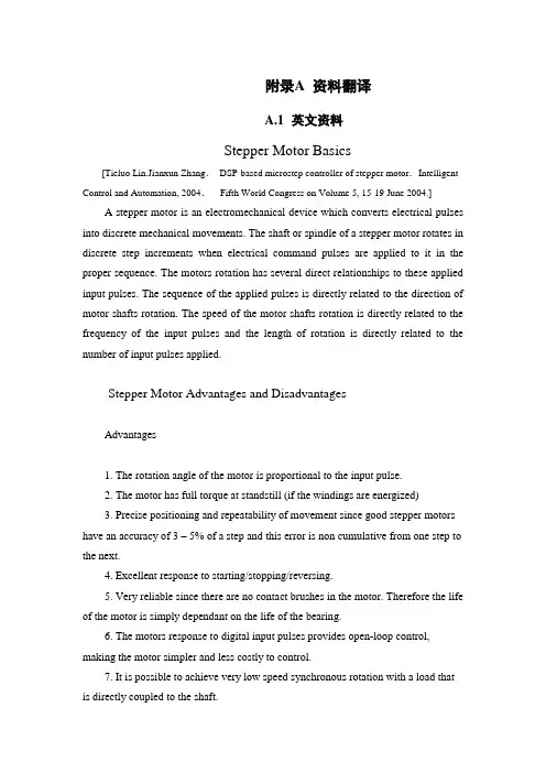
资料翻译英文资料Stepper Motor Basics[TieluoLin.Jianxun Zhang.DSP-based microstep controller of stepper motor.Intelligent Control and Automation, 2004.Fifth World Congress on Volume 5, 15-19 June 2004.]A stepper motor is an electromechanical device which converts electrical pulses into discrete mechanical movements. The shaft or spindle of a stepper motor rotates in discrete step increments when electrical command pulses are applied to it in the proper sequence. The motors rotation has several direct relationships to these applied input pulses. The sequence of the applied pulses is directly related to the direction of motor shafts rotation. The speed of the motor shafts rotation is directly related to the frequency of the input pulses and the length of rotation is directly related to the number of input pulses applied.Stepper Motor Advantages and DisadvantagesAdvantages1. The rotation angle of the motor is proportional to the input pulse.2. The motor has full torque at standstill (if the windings are energized)3. Precise positioning and repeatability of movement since good stepper motors have an accuracy of 3 – 5% of a step and this error is non cumulative from one step to the next.4. Excellent response to starting/stopping/reversing.5. Very reliable since there are no contact brushes in the motor. Therefore the life of the motor is simply dependant on the life of the bearing.6. The motors response to digital input pulses provides open-loop control, making the motor simpler and less costly to control.7. It is possible to achieve very low speed synchronous rotation with a load that is directly coupled to the shaft.8. A wide range of rotational speeds can be realized as the speed is proportional to the frequency of the input pulses.Disadvantages1. Resonances can occur if not properly controlled.2. Not easy to operate at extremely high speeds.Open Loop OperationOne of the most significant advantages of a stepper motor is its ability to be accurately controlled in an open loop system. Open loop control means no feedback information about position is needed. This type of control eliminates the need for expensive sensing and feedback devices such as optical encoders. Your position is known simply by keeping track of the input step pulses.Stepper Motor TypesThere are three basic stepper motor types. They are :• Variable-reluctance• Permanent-magnet• HybridVariable-reluctance (VR)This type of stepper motor has been around for a long time. It is probably the easiest to understand from a structural point of view. Figure 1 shows a cross section of a typical V.R. stepper motor. This type of motor consists of a soft iron multi-toothed rotor and a wound stator. When the stator windings are energized with DC current the poles become magnetized. Rotation occurs when the rotor teeth are attracted to the energized stator poles.Figure 1. Cross-section of a variablereluctance(VR) motor.Permanent Magnet (PM)Often referred to as a “tin can” or “canstock” motor the permanent magnet step motor is a low cost and low resolution type motor with typical step angles of 7.5° to 15°. (48 –24steps/revolution) PM motors as the name implies have permanent magnets added to the motor structure. The rotor no longer has teeth as with the VR motor. Instead the rotor is magnetized with alternating north and south poles situated in a straight line parallel to the rotor shaft. These magnetized rotor poles provide an increased magnetic flux intensity and because of this the PM motor exhibits improved torque characteristics when compared with the VR type.Hybrid (HB)The hybrid stepper motor is more expensive than the PM stepper motor but provides better performance with respect to step resolution, torque and speed. Typical step angles for the HB stepper motor range from 3.6°to 0.9°(100 –400 steps per revolution). Thehybrid stepper motor combines the best features of both the PM and VR type stepper motors. The rotor is multi-toothed like the VR motor and contains an axially magnetized concentric magnet around its shaft. The teeth on the rotor provide an even better path which helps guide the magnetic flux to preferred locations in theairgap. This further increases the detent, holding and dynamic torque characteristics of the motor when compared with both the VR and PM types.The two most commonly used types of stepper motors are the permanent magnet and the hybrid types. If a designer is not sure which type will best fit his applications requirements he should first evaluate the PM type as it is normally several times less expensive. If not then the hybrid motor may be the right choice.There also excist some special stepper motor designs. One is the disc magnet motor. Here the rotor is designed sa a disc with rare earth magnets, See fig. 5 . This motor type has some advantages such as very low inertia and a optimized magnetic flow path with no coupling between the two stator windings. These qualities are essential in some applications.Size and PowerIn addition to being classified by their step angle stepper motors are also classified according to frame sizes which correspond to the diameter of the body of the motor. For instance a size 11 stepper motor has a body diameter of approximately 1.1 inches. Likewise a size 23 stepper motor has a body diameter of 2.3 inches (58 mm), etc. The body length may however, vary from motor to motor within the same frame size classification. As a general rule the available torque output from a motor of a particular frame size will increase with increased body length.Power levels for IC-driven stepper motors typically range from below a watt for very small motors up to 10 –20 watts for larger motors. The maximum power dissipation level or thermal limits of the motor are seldom clearly stated in the motor manufacturersdata. To determine this we must apply the relationship P=V×I For example, a size 23 step motor may be rated at 6V and 1A per phase. Therefore, with two phases energizedthe motor has a rated power dissipation of 12 watts. It is normal practice to rate a stepper motor at the power dissipation level where the motor case rises 65°C above the ambient in still air. Therefore, if the motor can be mounted to a heatsink it is oftenpossible to increase the allowable power dissipation level. This is important as the motor is designed to be and should be used at its maximum power dissipation ,to be efficient froma size/output power/cost point of view.When to Use a StepperMotorA stepper motor can be a good choice henever controlled movement is equired. They can be used to advantage in applications where you need to control rotation angle, speed, position and synchronism. Because of the inherent advantages listed previously, stepper motors have found their place in many different applications. Some of these include printers, plotters, highend office equipment, hard disk drives, medical equipment, fax machines, automotive and many more.The Rotating Magnetic FieldWhen a phase winding of a stepper motor is energized with current a magnetic flux is developed in the stator. The d When a phase winding of a stepper motor is energized with current a magnetic flux is developed irection of this flux is determined by the “Right Ha ndRule” which states: “If the coil is grasped in the right hand with the fingers pointing in the direction of the current in the winding (the thumb is extended at a 90°angleto the fingers), then the thumb will point in the direction of the magnetic field.”Figure 2 shows the magnetic flux path developed when phase B is energized with winding current in the direction shown. The rotor then aligns itself so that the flux opposition is minimized. In this case the motor would rotate clockwise so that its south pole aligns with the north pole of the stator B at position 2 and its north pole aligns with the south pole of stator B at position 6. To get the motor to rotate we can now see that we must provide a sequence of energizing the stator windings in such a fashion that provides a rotating magnetic flux field which the rotor follows due to magnetic attraction.Figure 2 Magnetic flux path through atwo-pole stepper motor with a lag betweenthe rotor and stator.Torque GenerationThe torque produced by a stepper motor depends on several factors.• The step rate• The drive current in the windings• The drive design or typeIn a stepper motor a torque is developed when the magnetic fluxes of the rotor and stator are displaced from each other. The stator is made up of a high permeability magnetic material. The presence of this high permeability material causes the magnetic flux to be confined for the most part to the paths defined by the stator structure in the same fashion that currents are confined to the conductors of an electronic circuit. This serves to concentrate the flux at the stator poles. Thetorque output produced by the motor is proportional to the intensity of the magnetic flux generated when the winding is energized.The basic relationship which defines the intensity of the magneticflux is defined by:H = (N ×i) ÷ l where:N = The number of winding turnsi = currentH = Magnetic field intensityl = Magnetic flux path lengthThis relationship shows that the magnetic flux intensity and consequently the torque is proportional to the number of winding turns and the current and inversely proportional to the length of the magnetic flux path. From this basic relationship one can see that the same frame size stepper motor could have very different torque output capabilities simply by changing the winding parameters. More detailed information on how the winding parameters affect the output capability of the motor can be found in the application note entitled “DriveCircuit Basics”.Stepping ModesThe following are the most common drive modes.• Wave Drive (1 phase on)• Full Step Drive (2 phases on)• Half Step Drive (1 & 2 phases on)• Micro stepping (Continuously varying motor currents)For the following discussions please refer to the figure 3.Figure 3 Unipolar and bipolar wound stepper motors.In Wave Drive only one winding is energized at any given time. The stator is energized according to the sequence A B A B and the rotor steps from position8 2 4 6. For unipolar and bipolar wo und motors with the same winding parameters this excitation mode would result in the same mechanical position. The disadvantage of this drive mode is that in the unipolar wound motor you are only using 25% and in the bipolar motor only 50% of the total motor winding at any given time. This means that you are not getting the maximum torque output from the motor.In Full Step Drive you are energizingtwo phases at any given time.The stator is energized according to the sequence AB A B A B AB and the rotor steps from position 1 3 5 7 . Full step mode results in the same angular movement as 1 phase on drive but the mechanical position is offset by one half of a fullstep. The torque output of the unipolar wound motor is lower than the bipolar motor (for motors with the same winding parameters) since the unipolar motor uses only 50% of the available winding while the bipolar motor uses the entire winding.Half Step Drive combines both wave and full step (1&2 phases on) drive modes. Every second step onlyone phase is energized and during the other steps one phase on each stator. The stator is energized according to the sequence AB B A B A A B B A B A and the rotor steps from position 1 2 3 4 5 6 7 8. This results in angular movements that are half of those in 1- or 2-phases-on drive modes. Half stepping can reduce a phenomena referred to as resonance which can be experiencedin 1- or 2-phases-on drive modes.The excitation sequences for the above drive modes are summarized in Table 1. Table 1. Excitation sequences for different drive modesIn Microstepping Drive the currents in the windings are continuously varying to be able to break up one full step into many smaller discrete steps. More information on microstepping can be found in the microstepping chapter.Single Step Response and ResonancesThe single-step response characteristics of a stepper motor is shown in figure 4.Figure 4 Single step response vs. time.When one step pulse is applied to a stepper motor the rotor behaves in a manner as defined by the above curve.The step time t is the time it takes the motor shaft to rotate one step angle once the first step pulse is applied. This step time is highly dependent on the ratio of torque to inertia (load) as well as the type of driver used.Since the torque is a function of the displacement it follows that the acceleration will also be. Therefore, when moving in large step increments a high torque is developed and consequently a high acceleration. This can cause overshots and ringing as shown. The settling time T is the time it takes these oscillations or ringing to cease. In certain applications this phenomena can be undesirable. It is possible to reduce or eliminate this behaviour by microstepping the stepper motor. For more information on micro stepping please consult the microstepping note.Stepper motors can often exhibit a phenomena refered to as resonance at certain step rates. This can be seen as a sudden loss or drop in torque at certain speeds which can result in missed steps or loss of synchronism. It occurs when the input step pulserate coincides with the natural oscillation frequency of the rotor. Often there is a resonance area around the 100 – 200 pps region and also one in the high step pulse rate region. The resonance phenomena of a stepper motor comes from its basic construction and therefore it is not possible to eliminate it completely. It is also dependent upon the load conditions. It can be reduced by driving the motor in half or micro stepping modes.中文译文步进电机基础[林铁国,张建勋.基于DSP的微控制器的步进电机控制和自动化, 2004 。
步进电机的的基本原理中英文翻译English translation of the stepping motor basic principle步进电机作为执行元件,是机电一体化的关键产品之一,广泛应用在各种自动化控制系统中。
随着微电子和计算机技术的发展,步进电机的需求量与日俱增,在各个国民经济领域都有应用。
The stepping motor as executing components, electromechanical integration is one of the key products, widely used in a variety of automatic control systems. With the development of microelectronics and computer technology, the stepper motor demand grow with each passing day, has been applied in various fields of the national economy.步进电机是一种将电脉冲转化为角位移的执行机构。
当步进驱动器接收到一个脉冲信号,它就驱动步进电机按设定的方向转动一个固定的角度(称为“步距角”),它的旋转是以固定的角度一步一步运行的。
可以通过控制脉冲个数来控制角位移量,从而达到准确定位的目的;同时可以通过控制脉冲频率来控制电机转动的速度和加速度,从而达到调速的目的。
步进电机可以作为一种控制用的特种电机,利用其没有积累误差(精度为100%)的特点,广泛应用于各种开环控制。
Stepping motor is a kind of electrical pulses into angular displacement of the implementing agencies. When stepping drive receives a pulse signal, it drives stepper motor rotate in the direction set by a fixed angle ( called the " step " ), it is the rotation at a fixed angle step by step operation. The number of pulses to control the amount of angular displacement through the control, so as to achieve the purpose of accurate positioning; also can control the pulse frequency to control motor rotation speed and acceleration, so as to achieve the purpose of speed. Special motor stepper motor control can be used as a, using its no accumulation of error ( accuracy of 100% ) characteristics, widely used in all kinds of open-loop control.现在比较常用的步进电机包括反应式步进电机(VR)、永磁式步进电机(PM)、混合式步进电机(HB)和单相式步进电机等。
Step Motor&Servo Motor Systems and ControlsMotion Architect® Software Does the Work for You... Configure ,Diagnose, Debug Compumotor’s Motion Architect is a Microsoft® Windows™-based software development tool for 6000Series products that allows you to automatically generate commented setup code, edit and execute motion control programs, and create a custom operator test panel. The heart of Motion Architect is the shell, which provides an integrated environment to access the following modules.• System Con figurator—This module prompts you to fill in all pertinent set-up information to initiate motion. Configurable to the specific 6000 Series product that is selected, the information is then used to generate actual 6000-language code that is the beginning of your program.• Program Editor—This module allows you to edit code. It also has the commands available through ―Help‖ menus. A user’s guide is provided on disk.• Terminal Emulator—This module allows you to interact directly with the 6000 product. ―Help‖ is again available with all commands and their definitions available for reference. • Test Panel—You can simulate your programs, debug programs, and check for program flow using this module.Motion Architect® has been designed for use with all 6000 Series products—for both servo and stepper technologies. The versatility of Windows and the 6000 Series language allow you to solve applications ranging from the very simple to the complex.Motion Architect comes standard with each of the 6000 Series products and is a tool that makes using these controllers even more simple—shortening the project development time considerably. A value-added feature of Motion Architect, when used with the 6000 Servo Controllers, is its tuning aide. This additional module allows you to graphically display a variety of move parameters and see how these parameters change based on tuning values.Using Motion Architect, you can open multiple windows at once. For example, both the Program Editor and Terminal Emulator windows can be opened to run the program, get information, and then make changes to the program.On-line help is available throughout Motion Architect, including interactive access to the contents of the Compumotor 6000 Series Software Reference Guide.SOLVING APPLICATIONS FROM SIMPLE TOCOMPLEXServo Control is Yours with Servo Tuner SoftwareCompumotor combines the 6000 Series servo controllers with Servo Tuner software. The Servo Tuner is an add-on module that expands and enhances the capabilities of Motion Architect®.Motion Architect and the Servo Tuner combine to provide graphical feedback ofreal-time motion information and provide an easy environment for setting tuning gains and related systemparameters as well as providing file operations to save and recall tuning sessions.Draw Your Own Motion Control Solutions with Motion Toolbox Software Motion Toolbox™ is an extensive library of LabVIEW® virtual instruments (VIs) for icon-based programming of Compumotor’s 6000 Series motion controllers.When using Motion Toolbox with LabVIEW, programming of the 6000 Series controller is accomplished by linking graphic icons, or VIs, together to form a block diagram. Motion Toolbox’s has a library of more than 150 command,status, and example VIs. All command and status VIs include LabVIEW source diagrams so you can modify them, if necessary, to suit your particular needs. Motion Toolbox als user manual to help you gut up and running quickly.comprehensiveM Software for Computer-Aided Motion Applications CompuCAM is a Windows-based programming package that imports geometry from CAD programs, plotter files, or NC programs and generates 6000 code compatible with Compumotor’s 6000 Series motion controllers. Available for purchase from Compumotor, CompuCAM is an add-on module which is invoked as a utility from the menu bar of Motion Architect.From CompuCAM, run your CAD software package. Once a drawing is created, save it as either a DXF file, HP-GL plot file or G-code NC program. This geometry is then imported into CompuCAM where the 6000 code is generated. After generating the program, you may use Motion Architect functions such as editing or downloading the code for execution.Motion Builder Software for Easy Programming of the 6000 SeriesMotion Builder revolutionizes motion control programming. This innovative software allows programmers to program in a way they are familiar with—a flowchart-style method. Motion Builder decreases the learning curve and makes motion control programming easy.Motion Builder is a Microsoft Windows-based graphical development environment which allows expert and novice programmers to easily program the 6000 Series products without learning a new programming language. Simply drag and drop visual icons that represent the motion functions you want to perform.Motion Builder is a complete application development environment. In addition to visually programming the 6000 Series products, users may configure, debug, download, and execute the motion program.SERVO VERSUS STEPPER... WHAT YOU NEED TOKNOWMotor Types and Their ApplicationsThe following section will give you some idea of the applications that are particularly appropriate for each motor type, together with certain applications that are best avoided. It should be stressed that there is a wide range of applications which can be equally well met by more than one motor type, and the choice will tend to be dictated by customer preference, previous experience or compatibility with existing equipment.A helpful tool for selecting the proper motor for your applicat ion is Compumotor’s Motor Sizing and Selection software package. Using this software, users can easily identify the appropriate motor size and type.High torque, low speedcontinuous duty applications are appropriate to the step motor. At low speeds it is very efficient in terms of torque output relative to both size and input power. Microstepping can be used to improve smoothness in lowspeed applications such as a metering pump drive for very accurate flow control.High torque, high speedcontinuous duty applications suit the servo motor, and in fact a step motor should be avoided in such applications because the high-speed losses can cause excessive motor heating.Short, rapid, repetitive movesare the natural domain of the stepper due to its high torque at low speeds, goodtorque-to-inertia ratio and lack of commutation problems. The brushes of the DC motor can limit its potential for frequent starts, stops and direction changes.Low speed, high smoothness application sare appropriate for microstepping or direct drive servos.Applications in hazardous environmentsor in a vacuum may not be able to use a brushed motor. Either a stepper or a brushless motor is called for, depending on the demands of the load. Bear in mind that heat dissipation may be a problem in a vacuum when the loads are excessive. SELECTING THE MOTOR THAT SUITS YOUR APPLICATION IntroductionMotion control, in its widest sense, could relate to anything from a welding robot to the hydraulic system in a mobile crane. In the field of Electronic Motion Control, we are primarily concerned with systems falling within a limited power range, typically up to about 10HP (7KW), and requiring precision in one or more aspects. This may involve accurate control of distance or speed, very often both, and sometimes other parameters such as torque or acceleration rate. In the case of the two examples given, the weldingrobot requires precise control of both speed and distance; the crane hydraulic system uses the driver as the feedback system so its accuracy varies with the skill of the operator. This wouldn’t be considered a motion control system in the strict sense of the term.Our standard motion control system consists of three basic elements:Fig. 1 Elements of motion control systemThe motor. This may be a stepper motor (either rotary or linear), a DC brush motor or a brushless servo motor. The motor needs to be fitted with some kind of feedback device unless it is a stepper motor.Fig. 2 shows a system complete with feedback to control motor speed. Such a system is known as a closed-loop velocity servo system.Fig. 2 Typical closed loop (velocity) servo systemThe drive. This is an electronic power amplifier thatdelivers the power to operate the motor in response to low-level control signals. In general, the drive will be specifically designed to operate with a particular motor type –you can’t use a stepper drive to operate a DC brush motor, for instance.Application Areas of Motor TypesStepper MotorsStepper Motor BenefitsStepper motors have the following benefits:• Low cost• Ruggedness• Simplicity in construction• High reliability• No maintenance• Wide acceptance• No tweaking to stabilize• No feedback components are needed• They work in just about any environment• Inherently more failsafe than servo motors.There is virtually no conceivable failure within the stepper drive module that could cause the motor to run away. Stepper motors are simple to drive and control in an open-loop configuration. They only require four leads. They provide excellent torque at low speeds, up to 5 times the continuous torque of a brush motor of the same frame size or double the torque of the equivalent brushless motor. This often eliminates the need for a gearbox. A stepper-driven-system is inherently stiff, with known limits to the dynamic position error.Stepper Motor DisadvantagesStepper motors have the following disadvantages:• Resonance effects and relatively long settlingtimes• Rough performance at low speed unless amicrostep drive is used• Liability to undetected position loss as a result ofoperating open-loop• They consume current regardless of loadconditions and therefore tend to run hot• Losses at speed are relatively high and can causeexcessive heating, and they are frequently noisy(especially at high speeds).• They can exhibit lag-lead oscillation, which isdifficult to damp. There is a limit to their availablesize, and positioning accuracy relies on themechanics (e.g., ballscrew accuracy). Many ofthese drawbacks can be overcome by the use ofa closed-loop control scheme.Note: The Compumotor Zeta Series minimizes orreduces many of these different stepper motor disadvantages.There are three main stepper motor types:• Permanent Magnet (P.M.) Motors• Variable Reluctance (V.R.) Motors• Hybrid MotorsWhen the motor is driven in its full-step mode, energizing two windings or ―phases‖ at a time (see Fig. 1.8), the torque available on each step will be the same (subject to very small variations in the motor and drive characteristics). In the half-step mode, we are alternately energizing two phases and then only one as shown in Fig. 1.9. Assuming the drive delivers the same winding current in each case, this will cause greater torque to be produced when there are two windings energized. In other words, alternate steps will be strong and weak. This does not represent a major deterrent to motor performance—the available torque is obviously limited by the weaker step, but there will be a significant improvement in low-speed smoothness over the full-step mode.Clearly, we would like to produce approximately equal torque on every step, and thistorque should be at the level of the stronger step. We can achieve this by using a higher current level when there is only one winding energized. This does not over dissipate the motor because the manufacturer’s current rating assumes two phases to be energized the current rating is based on the allowable case temperature). With only one phase energized, the same total power will be dissipated if the current is increased by 40%. Using this higher current in the one-phase-on state produces approximately equal torque on alternate steps (see Fig. 1.10).Fig. 1.8 Full step current, 2-phase onFig. 1.9 Half step currentFig. 1.10 Half step current, profiledWe have seen that energizing both phases with equal currents produces an intermediate step position half-way between the one-phase-on positions. If the two phase currents are unequal, the rotor position will be shifted towards the stronger pole. This effect is utilized in the microstepping drive, which subdivides the basic motor step by proportioning thecurrent in the two windings. In this way, the step size is reduced and the low-speed smoothness is dramatically improved. High-resolution microstep drives divide the full motor step into as many as 500 microsteps, giving 100,000 steps per revolution. In this situation, the current pattern in the windings closely resembles two sine waves with a 90°phase shift between them (see Fig. 1.11). The motor is now being driven very much as though it is a conventional AC synchronous motor. In fact, the stepper motor can be driven in this way from a 60 Hz-US (50Hz-Europe) sine wave source by including a capacitor in series with one phase. It will rotate at 72 rpm.Fig. 1.11 Phase currents in microstep modeStandard 200-Step Hybrid MotorThe standard stepper motor operates in the same way as our simple model, but has a greater number of teeth on the rotor and stator, giving a smaller basic step size. The rotor is in two sections as before, but has 50 teeth on each section. The half-tooth displacement between the two sections is retained. The stator has 8 poles each with 5 teeth, making a total of 40 teeth (see Fig. 1.12).Fig. 1.12 200-step hybrid motorIf we imagine that a tooth is placed in each of the gaps between the stator poles, there would be a total of 48 teeth, two less than the number of rotor teeth. So if rotor and stator teeth are aligned at 12 o’clock, they will also be aligned at 6 o’clock. At 3 o’clock and 9 o’clock the teeth will be misaligned. However, due to the displacement between the sets of rotor teeth, alignment will occur at 3 o’clock and 9 o’clock at the other end of the rotor.The windings are arranged in sets of four, and wound such that diametrically-oppositepoles are the same. So referring to Fig. 1.12, the north poles at 12 and 6 o’clock attract the south-pole teeth at the front of the rotor; the south poles at 3 and 9 o’clock attract the north-pole teeth at the back. By switching current to the second set of coils, the stator field pattern rotates through 45°. However, to align with this new field, the rotor only has to turn through 1.8°. This is equivalent to one quarter of a tooth pitch on the rotor, giving 200 full steps per revolution.Note that there are as many detent positions as there are full steps per rev, normally 200. The detent positions correspond with rotor teeth being fully aligned with stator teeth. When power is applied to a stepper drive, it is usual for it to energize in the ―zero phase‖ state in which there is current in both sets of windings. The resulting rotor position does not correspond with a natural detent position, so an unloaded motor will always move by at least one half step at power-on. Of course, if the system was turned off other than in the zero phase state, or the motor is moved in the meantime, a greater movement may be seen at power-up.Another point to remember is that for a given current pattern in the windings, there are as many stable positions as there are rotor teeth (50 for a 200-step motor). If a motor isde-synchronized, the resulting positional error will always be a whole number of rotor teeth or a multiple of 7.2°. A motor cannot ―miss‖ individual steps – position errors of one or two steps must be due to noise, spurious step pulses or a controller fault.Fig. 2.19 Digital servo driveDigital Servo Drive OperationFig. 2.19 shows the components of a digital drive for a servo motor. All the main control functions are carried out by the microprocessor, which drives a D-to-A convertor to produce an analog torque demand signal. From this point on, the drive is very much like an analog servo amplifier.Feedback information is derived from an encoder attached to the motor shaft. The encoder generates a pulse stream from which the processor can determine the distance travelled, and by calculating the pulse frequency it is possible to measure velocity.The digital drive performs the same operations as its analog counterpart, but does so by solving a series of equations. The microprocessor is programmed with a mathematical model (or ―algorithm‖) of the equivalent analog system. This model predicts the behavior of the system. In response to a given input demand and output position. It also takes into account additional information like the output velocity, the rate of change of the input and the various tuning settings.To solve all the equations takes a finite amount of time, even with a fast processor – this time is typically between 100ms and 2ms. During this time, the torque demand must remain constant at its previously-calculated value and there will be no response to a change at the input or output. This ―update time‖ therefore becomes a critical factor in the performance of a digital servo and in a high-performance system it must be kept to a minimum.The tuning of a digital servo is performed either by pushbuttons or by sending numerical data from a computer or terminal. No potentiometer adjustments are involved. The tuning data is used to set various coefficients in the servo algorithm and hence determines the behavior of the system. Even if the tuning is carried out using pushbuttons, the final values can be uploaded to a terminal to allow easy repetition.In some applications, the load inertia varies between wide limits – think of an arm robot that starts off unloaded and later carries a heavy load at full extension. The change in inertia may well be a factor of 20 or more, and such a change requires that the drive isre-tuned to maintain stable performance. This is simply achieved by sending the new tuning values at the appropriate point in the operating cycle.步进电机和伺服电机的系统控制运动的控制者---软件:只要有了软件,它可以帮助我们配置改装、诊断故障、调试程序等。
Stepping Motor TypesIntroductionStepping motors come in two varieties, permanent magnet and variable reluctance (there are also hybrid motors, which are indistinguishable from permanent magnet motors from the controller's point of view). Lacking a label on the motor, you can generally tell the two apart by feel when no power is applied. Permanent magnet motors tend to "cog" as you twist the rotor with your fingers, while variable reluctance motors almost spin freely (although they may cog slightly because of residual magnetization in the rotor). You can also distinguish between the two varieties with an ohmmeter. Variable reluctance motors usually have three (sometimes four) windings, with a common return, while permanent magnet motors usually have two independent windings, with or without center taps. Center-tapped windings are used in unipolar permanent magnet motors.Stepping motors come in a wide range of angular resolution. The coarsest motors typically turn 90 degrees per step, while high resolution permanent magnet motors are commonly able to handle 1.8 or even 0.72 degrees per step. With an appropriate controller, most permanent magnet and hybrid motors can be run in half-steps, and some controllers can handle smaller fractional steps or microsteps.For both permanent magnet and variable reluctance stepping motors, if just one winding of the motor is energised, the rotor (under no load) will snap to a fixed angle and then hold that angle until the torque exceeds the holding torque of the motor, at which point, the rotor will turn, trying to hold at each successive equilibrium point.Variable Reluctance MotorsFigure 1.1If your motor has three windings, typically connected as shown in the schematic diagram in Figure 1.1, with one terminal common to all windings, it is most likely a variable reluctance stepping motor. In use, the common wire typically goes to the positive supply and the windings are energized in sequence.The cross section shown in Figure 1.1 is of 30 degree per step variable reluctance motor. The rotor in this motor has 4 teeth and the stator has 6 poles, with each winding wrapped around two opposite poles. With winding number 1 energised, the rotor teeth marked X are attracted to this winding's poles. If the current through winding 1 is turned off and winding 2 is turned on, the rotor will rotate 30 degrees clockwise so that the poles marked Y line up with the poles marked 2.To rotate this motor continuously, we just apply power to the 3 windings in sequence. Assuming positive logic, where a 1 means turning on the current through a motor winding, the following control sequence will spin the motor illustrated in Figure 1.1 clockwise 24 steps or 2 revolutions:Winding 1 1001001001001001001001001Winding 2 0100100100100100100100100Winding 3 0010010010010010010010010 time --->The section of this tutorial on Mid-Level Control provides details on methods for generating such sequences of control signals, while the section on Control Circuits discusses the power switching circuitry needed to drive the motor windings from such control sequences.There are also variable reluctance stepping motors with 4 and 5 windings, requiring 5 or 6 wires. The principle for driving these motors is the same as that for the three winding variety, but it becomes important to work out the correct order to energise the windings to make the motor step nicely.The motor geometry illustrated in Figure 1.1, giving 30 degrees per step, uses the fewest number of rotor teeth and stator poles that performs satisfactorily. Using more motor poles and more rotor teeth allows construction of motors with smaller step angle. Toothed faces on each pole and a correspondingly finely toothed rotor allows for step angles as small as a few degrees.Unipolar MotorsFigure 1.2Unipolar stepping motors, both Permanent magnet and hybrid stepping motors with 5 or 6 wires are usually wired as shown in the schematic in Figure 1.2, with a center tap on each of two windings. In use, the center taps of the windings are typically wired to the positive supply, and the two ends of each winding are alternately grounded to reverse the direction of the field provided by that winding.The motor cross section shown in Figure 1.2 is of a 30 degree per step permanent magnet or hybrid motor -- the difference between these two motor types is not relevant at this level of abstraction. Motor winding number 1 is distributed between the top and bottom stator pole, while motor winding number 2 is distributed between the left and right motor poles. The rotor is a permanent magnet with 6 poles, 3 south and 3 north, arranged around its circumfrence.For higher angular resolutions, the rotor must have proportionally more poles. The 30 degree per step motor in the figure is one of the most common permanent magnet motor designs, although 15 and 7.5 degree per step motors are widely available. Permanent magnet motors with resolutions as good as 1.8 degrees per step are made, and hybrid motors are routinely built with 3.6 and 1.8 degrees per step, with resolutions as fine as 0.72 degrees per step available.As shown in the figure, the current flowing from the center tap of winding 1 to terminal a causes the top stator pole to be a north pole while the bottom stator pole is a south pole. This attracts the rotor into the position shown. If the power to winding 1 is removed and winding 2 is energised, the rotor will turn 30 degrees, or one step.To rotate the motor continuously, we just apply power to the two windings in sequence. Assuming positive logic, where a 1 means turning on the current through a motor winding, the following two control sequences will spin the motor illustrated in Figure 1.2 clockwise 24 steps or 2 revolutions:Winding 1a 1000100010001000100010001Winding 1b 0010001000100010001000100Winding 2a 0100010001000100010001000Winding 2b 0001000100010001000100010 time --->Winding 1a 1100110011001100110011001Winding 1b 0011001100110011001100110Winding 2a 0110011001100110011001100Winding 2b 1001100110011001100110011 time --->Note that the two halves of each winding are never energized at the same time. Both sequences shown above will rotate a permanent magnet one step at a time. The top sequence only powers one winding at a time, as illustrated in the figure above; thus, it uses less power. The bottom sequence involves powering two windings at a time and generally produces a torque about 1.4 times greater than the top sequence while using twice as much power.The section of this tutorial on Mid-Level Control provides details on methods for generating such sequences of control signals, while the section on Control Circuits discusses the power switching circuitry needed to drive the motor windings from such control sequences.The step positions produced by the two sequences above are not the same; as a result, combining the two sequences allows half stepping, with the motor stopping alternately at the positions indicated by one or the other sequence. The combined sequence is as follows:Winding 1a 11000001110000011100000111Winding 1b 00011100000111000001110000Winding 2a 01110000011100000111000001Winding 2b 00000111000001110000011100time --->Bipolar MotorsFigure 1.3Bipolar permanent magnet and hybrid motors are constructed with exactly the same mechanism as is used on unipolar motors, but the two windings are wired more simply, with no center taps. Thus, the motor itself is simpler but the drive circuitry needed to reverse the polarity of each pair of motor poles is more complex. The schematic in Figure 1.3 shows how such a motor is wired, while the motor cross section shown here is exactly the same as the cross section shown in Figure 1.2.The drive circuitry for such a motor requires an H-bridge control circuit for each winding; these are discussed in more detail in the section on Control Circuits. Briefly, an H-bridge allows the polarity of the power applied to each end of each winding to be controlled independently. The control sequences for single stepping such a motor are shown below, using + and - symbols to indicate the polarity of the power applied to each motor terminal:Terminal 1a +---+---+---+--- ++--++--++--++--Terminal 1b --+---+---+---+- --++--++--++--++Terminal 2a -+---+---+---+-- -++--++--++--++-Terminal 2b ---+---+---+---+ +--++--++--++--+ time --->Note that these sequences are identical to those for a unipolar permanent magnet motor, at an abstract level, and that above the level of the H-bridge power switching electronics, the control systems for the two types of motor can be identical.Note that many full H-bridge driver chips have one control input to enable the output and another to control the direction. Given two such bridge chips, one per winding, the following control sequences will spin the motor identically to the control sequences given above:Enable 1 1010101010101010 1111111111111111Direction 1 1x0x1x0x1x0x1x0x 1100110011001100Enable 2 0101010101010101 1111111111111111Direction 2 x1x0x1x0x1x0x1x0 0110011001100110 time --->To distinguish a bipolar permanent magnet motor from other 4 wire motors, measure the resistances between the different terminals. It is worth noting that some permanent magnet stepping motors have 4 independent windings, organized as two sets of two. Within each set, if the two windings are wired in series, the result can be used as a high voltage bipolar motor. If they are wired in parallel, the result can be used as a low voltage bipolar motor. If they are wired in series with a center tap, the result can be used as a low voltage unipolar motor. Bifilar MotorsBifilar windings on a stepping motor are applied to the same rotor and stator geometry as a bipolar motor, but instead of winding each coil in the stator with a single wire, two wires are wound in parallel with each other. As a result, the motor has 8 wires, not four.In practice, motors with bifilar windings are always powered as either unipolar or bipolar motors. Figure 1.4 shows the alternative connections to the windings of such a motor.Figure 1.4To use a bifilar motor as a unipolar motor, the two wires of each winding are connected in series and the point of connection is used as a center-tap. Winding 1 in Figure 1.4 is shown connected this way.To use a bifilar motor as a bipolar motor, the two wires of each winding are connected either in parallel or in series. Winding 2 in Figure 1.4 is shown with a parallel connection; this allows low voltage high-current operation. Winding 1 in Figure 1.4 is shown with a series connection; if the center tap is ignored, this allows operation at a higher voltage and lower current than would be used with the windings in parallel.It should be noted that essentially all 6-wire motors sold for bipolar use are actually wound using bifilar windings, so that the external connection that serves as a center tap is actually connected as shown for winding 1 in Figure 1.4. Naturally, therefore, any unipolar motor may be used as a bipolar motor at twice the rated voltage and half the rated current as is given on the nameplate.The question of the correct operating voltage for a bipolar motor run as a unipolar motor, or for a bifilar motor with the motor windings in series is not as trivial as it might first appear. There are three issues: The current carrying capacity of the wire, cooling the motor, and avoiding driving the motor's magnetic circuits into saturation. Thermal considerations suggest that, if the windings are wired in series, the voltage should only be raised by the square root of 2. The magnetic field in the motor depends on the number of ampere turns; when the two half-windings are run in series, the number of turns is doubled, but because a well-designed motor has magnetic circuits that are close to saturation when the motor is run at its rated voltage and current, increasing the number of ampere-turns does not make the field any stronger. Therefore, when a motor is run with the two half-windings in series, the current should be halved in order to avoid saturation; or, in other words, the voltage across the motor winding should be the same as it was.For those who salvage old motors, finding an 8-wire motor poses a challenge! Which of the 8 wires is which? It is not hard to figure this out using an ohm meter, an AC volt meter, and a low voltage AC source. First, use the ohm meter to identify the motor leads that are connected to each other through the motor windings. Then, connect a low-voltage AC source to one of these windings. The AC voltage should be below the advertised operating voltage of the motor; voltages under 1 volt are recommended. The geometry of the magnetic circuits of the motor guarantees that the two wires of a bifilar winding will be strongly coupled for AC signals, while there should be almost no coupling to the other two wires. Therefore, probing with an AC volt meter should disclose which of the other three windings is paired to the winding under power. Multiphase MotorsFigure 1.5A less common class of permanent magnet or hybrid stepping motor is wired with all windings of the motor in a cyclic series, with one tap between each pair ofwindings in the cycle, or with only one end of each motor winding exposed while the other ends of each winding are tied together to an inaccessible internal connection. In the context of 3-phase motors, these configurations would be described as Delta and Y configurations, but they are also used with 5-phase motors, as illustrated in Figure 1.5. Some multiphase motors expose all ends of all motor windings, leaving it to the user to decide between the Delta and Y configurations, or alternatively, allowing each winding to be driven independently.Control of either one of these multiphase motors in either the Delta or Y configuration requires 1/2 of an H-bridge for each motor terminal. It is noteworthy that 5-phase motors have the potential of delivering more torque from a given package size because all or all but one of the motor windings are energised at every point in the drive cycle. Some 5-phase motors have high resolutions on the order of 0.72 degrees per step (500 steps per revolution).Many automotive alternators are built using a 3-phase hybrid geometry with either a permanent magnet rotor or an electromagnet rotor powered through a pair of slip-rings. These have been successfully used as stepping motors in some heavy duty industrial applications; step angles of 10 degrees per step have been reported.With a 5-phase motor, there are 10 steps per repeat in the stepping cycle, as shown below:Terminal 1 +++-----+++++-----++Terminal 2 --+++++-----+++++---Terminal 3 +-----+++++-----++++Terminal 4 +++++-----+++++-----Terminal 5 ----+++++-----+++++-time --->With a 3-phase motor, there are 6 steps per repeat in the stepping cycle, as shown below:Terminal 1 +++---+++---Terminal 2 --+++---+++-Terminal 3 +---+++---++time --->Here, as in the bipolar case, each terminal is shown as being either connected to the positive or negative bus of the motor power system. Note that, at each step, only one terminal changes polarity. This change removes the power from one winding attached to that terminal (because both terminals of the winding in question are of the same polarity) and applies power to one winding that was previously idle. Given the motor geometry suggested by Figure 1.5, this control sequence will drive the motor through two revolutions.To distinguish a 5-phase motor from other motors with 5 leads, note that, if the resistance between two consecutive terminals of the 5-phase motor is R, the resistance between non-consecutive terminals will be 1.5R.Note that some 5-phase motors have 5 separate motor windings, with a total of 10 leads. These can be connected in the star configuration shown above, using 5 half-bridge driver circuits, or each winding can be driven by its own full-bridge. While the theoretical component count of half-bridge drivers is lower, the availability of integrated full-bridge chips may make the latter approach preferable.步进电机•介绍•变磁阻电机•单极电机•双极电机•单一电机•多相电机介绍步进电动机分成两类、永磁和变磁阻(也有混合电机、永磁电机与从控制器的观点)。
步进电机运动控制系统外文文献翻译中英文外文文献翻译(含:英文原文及中文译文)文献出处:YH Lee. Stepper motor motion control system design [J]. Equipment Manufacturing Technology, 2015,2(6):31-41.英文原文Stepper motor motion control system designYH LeeAbstractStepper motors are open-loop control elements that convertelectrical pulse signals to angular or linear displacements. In the case of non-overload, the rotation speed and stop position of the motor depend only on the frequency and pulse number of the pulse signal, and is not affected by the load change, that is, a pulse signal is applied to the motor, and the motor rotates through a step angle. The existence of this linear relationship, coupled with the fact that the stepper motor has only periodic errors and no cumulative errors, is a feature. It is very simple to use a stepper motor to control the speed and position. Stepper motor speed control is generally to change the frequency of the input stepper motor pulse to achieve stepper motor speed control, because the stepper motor for each pulse to rotate afixed angle, so that you can control the stepper motor The time intervalfrom one pulse to the next pulse changes the frequency of the pulse. The length of the delay controls the step anglespecifically to change the rotation speed of the motor, thereby realizing the stepping motor speed control. In this design scheme, the internal timer of the AT89C51 microcontroller is used to change the frequency of the CP pulse to realize the control of the rotation speedof the stepper motor to realize the functions of the motor speed adjustment and forward and reverse rotation. The design takes into consideration that the CPU may be disturbed when executing instructions, causing the program to "run away" or enter the "endless loop". Therefore, the watchdog circuit is designed using a microprocessing system monitoring integrated chip manufactured by MAXIM. MAXI813. This article also gives the related hardware block diagram and software flow chart in detail, and has compiled the assembly language program.Keywords: stepper motor single chip microcomputer speed control systemIntroductionStepper motors were first developed by the British in 1920. The invention of the transistor in the late 1950s was also gradually applied to a stepping motor, which made it easier to control the digitization. After continuous improvement, today's stepper motors have been widely used in mechanical systems with high controllability such as high positioning accuracy, high decomposition performance, highresponsiveness, and reliability. In the production process, where automation, labor saving, andhigh efficiency are required, we can easily find traces of stepper motors, especially those that emphasize speed, position control, and flexible control applications that require precise command operation. The most. As an actuator, a stepper motor is one of the key products of electromechanical integration and is widely used in various automation control systems. With the development of microelectronics and computer technology, the demand for stepper motors is increasing day by day, and there are applications in various national economic fields. A stepper motor is an actuator that converts an electrical pulse signal into an angular or linear displacement. Stepper motors can be driven directly with digital signals and are very easy to use. The general motor is continuous rotation, while the stepper motor has two basic states of positioning and operation. When there is a pulse input, the stepping motor rotates step by step, and when it is given a pulse signal, it turns a certain angle. The angular displacement of the stepping motor is strictly proportional to the number of input pulses and is synchronized in time with the input pulse. Therefore, as long as the number of input pulses, the frequency, and the phase sequence of the motor windings are controlled, the desired rotation angle can be obtained. Speed and direction of rotation. When there is no pulse input, the air gap magnetic field can keep the rotor in the original position under theexcitation of the winding power supply. So it is very suitable forsingle chip microcomputer control. Stepper motors also have features such as fast start, precise stepping and positioning, and are thus widely used in CNC machine tools, plotters, printers, and optical instruments. Stepping motors have become the third category of motors except for DC motors and AC motors. Traditional electric motors, as electromechanical energy conversion devices, play a key role in human production and life into the electrification process. The stepper motor can be used as a special motor for control, and it is widely used in various open-loop control because it has no accumulated error (accuracy is 100%). Now more commonly used stepper motors include reactive stepper motors (VR), permanent magnet stepper motors (PM), hybrid stepper motors (HB), and single-phase stepper motors. Permanent-magnet type stepping motor is generally two-phase, small torque and volume, step angle is generally 7.5 degrees or 15 degrees; Reactive stepping motor is generally three-phase, can achieve large torque output, stepping The angle is generally 1.5 degrees, but the noise and vibration are large. The rotor of the reactive stepper motor is magnetically routed from a soft magnetic material, and the stator has a multi-phase excitation winding, which generates torque using a change in the magnetic permeability. Hybrid stepping motor refers to the advantage of mixing permanent magnet type and reactive type. It is divided into two phases and five phases: the two-phase step angle is generally 1.8 degrees andthe five-phase step angle is generally 0.72 degrees. This type of steppermotor is the most widely used and is also the stepper motor used in this subdivision drive scheme.1 stepper motor overview1. 1 stepper motor features:1) The accuracy of a typical stepper motor is 3-5% of the step angle and does not accumulate. 2) The allowable temperature of the stepper motor is high. Excessively high temperature of the stepping motor first demagnetizes the magnetic material of the motor, resulting in a drop in torque and even loss of synchronism. Therefore, the maximum temperature allowed for the appearance of the motor should depend on the demagnetization point of the magnetic material of different motors; generally, the demagnetization of the magnetic material. The points are all above 130 degrees Celsius, and some are even up to 200 degrees Celsius. Therefore, the external temperature of the stepper motor is completely normal at 80-90 degrees Celsius. 3) The torque of the stepper motor will decrease as the rotation speed increases. When the stepper motor rotates, the inductance of each phase winding of the motor will form a counter electromotive force; the higher the frequency, the greater the counter electromotive force. Under its effect, the motor's phase current decreases as the frequency (or speed) increases, causing the torque to drop. 4) The stepping motor can run normally at low speed,but it cannot start if it is higher than a certain speed, accompanied by howling. The stepper motorhas a technical parameter: No-load starting frequency, that is the pulse frequency that the stepping motor can start normally under no-load conditions. If the pulse frequency is higher than this value, the motor cannot start normally, and step loss or stall may occur. In the case of load, the starting frequency should be lower. If the motor is to be rotated at a high speed, the pulse frequency should have an acceleration process, that is, the starting frequency is low, and then it is increased to a desired high frequency (motor speed is raised from low speed to high speed) at a certain acceleration. TC \* MERGEFORMAT1. 2 working principle of stepping motorA stepper motor is a type of motor that is controlled by anelectrical pulse and converts the electrical pulse signal into a phase-shifted motor whose mechanical displacement and rotational speed are proportional to the number of pulses and the pulse frequency of the input motor winding. Each pulse signal can be stepped The feed motor rotates at a fixed angle. The number of pulses determines the total angle of rotation. The frequency of the pulse determines the speed of the motor. When the stepper receives a pulse signal, it drives the stepper motor to rotate in the set direction. At a fixed angle (called "step angle"), its rotation is performed step by step at a fixed angle. By controlling the number of pulses to control the angular displacement,so as to achieve the purpose of accurate positioning; At the same time, by controlling the pulse frequencyto control the speed and acceleration of the motor rotation, so asto achieve the purpose of speed control.2 Basic requirements for designStudy the characteristics, working principle, and specific speed regulation principle of stepper motor. TC \* MERGEFORMATBasic requirements The stepper motor uses a three-phase steppermotor with a power of 1W. When the speed is in the range of 0 to1000r/min, the maximum accuracy is 2%. To basically complete the graduation design, the stepper motor can perform precise speed control, positive and negative rotation, and it can not lose step when starting. Basically, there is no Oscillation, can complete the complete hardware circuit diagram, software design.3 Argumentation of the plan3.1 Determination of control methodsAlthough the stepper motor control is a relatively accurate, open-loop stepper motor control system has the advantages of low cost, simple, convenient control, etc., in the open-loop system of the stepper motor using the microcontroller, the frequency of the CP pulse of the control system or change The cycle is actually controlling the speed of the stepper motor. There are two ways the system can achieve stepper motor speed control. One is delay, the other is timing. The delay method is to call a delay subroutine after each commutation. After the delay isover, the commutation is executed again. In this way, CP pulses or commutation cycles with a certain frequency can be issued. The delay time of the delay subroutine and the time used by the commutation program are the cycles of the CP pulse. This method is simple, uses less resources, and is implemented by software. Different subroutines can be called to achieve different speeds. However, it takes a long time to process the CPU and cannot handle other tasks at runtime. Therefore, it is only suitable for a simpler control process. The timing method is to use the timer timing function in the microcontroller system to generate an arbitrary period of the timing signal, so that the period of the system output CP pulse can be conveniently controlled. When the timer is started, the timer counts up the system and its cycle starting from the loaded initial value. When the timer overflows, the timer generates an interrupt and the system transfers to execute the timer interrupt subroutine. The motor commutation subroutine is placed in the timer interrupt service routine. The timer interrupt is once and the motor is reversed once to achieve motor speed control. Since there is a certain time interval from the start of restarting the timer to the timer application interruption, the timing time is increased. In order to reduce this timing error and achieve accurate timing, it is necessary to make appropriate adjustments to the initial value of reloading counts. . The initial value of adjusted reloading mainly considers two factors and one is the time required to interrupt theresponse. The second is the time occupied by reloading the initial value instruction, including other instructions that interrupt the service program before reloading the initial value. After these two factors are combined, the correction amount of the reload count initial value takes 8 machine cycles, that is, the timing time is shortened by 8 machine cycles. When using the timer interrupt to control the motor shift, it is actually changing the size of the timer load value. In the control process, a discrete approach is used to approximate the ideal speed curve. In order to reduce the time for calculating the load value in each step, the load value required for the speed of each discrete point is fixed in the ROM of the system when the system is designed. The system uses the table look-up method to find the required load value in the system. Significantly reduce the time spent on CPU and improve the response speed of the system. Most stepper motor motion control systems are designed to run in an open-loop state, because the cost is low, and the position control inherent in the motion control technology can be provided without feedback. However, in some applications, more reliability, security, or product quality assurance is required. Therefore, closed-loop control is also an option. Here are some methods for achieving closed-loop control of stepper motors: 1) Step-by-step confirmation, This is the simplest displacement control, using a low-value optical encoder to calculate the amount of step movement. A simple loop compares the stepper motor with the commandverification and verifies that the stepper motor moves to the expected position; 2) Back-EMF, a sensorless detection method, uses a stepper motor's back EMF (eleCtromotiveCe, emf) signal , Measure and control speed. When the back-EMF voltage drops to the monitoring detection level, the closed-loop control is changed to the standard open-loop to complete the final displacement movement; 3) Full-servo control refers to the full-time use of feedback devices for stepper motors - encoders, decoding , or other feedback sensors to more accurately control the stepper motor displacement and torque. Other methods include a variety of different back-EMF control motor parameter measurements and software techniques that some manufacturers use. Here, the stepper drive monitors and measures the motor coils and uses voltage current information to increase the stepper motor control. Positive damping uses this information to block the speed of vibration, producing more usable torque output and reducing torque-induced mechanical vibration losses. No encoder installation monitoring uses information to detect the loss of synchronous speed. Conventional stepper motor control usually employs feedback devices and non-sensing methods, and is an effective method to implement a sports application with safety requirements, dangerous conditions or high accuracy requirements. Most stepper motor-based systems typically operate in an open-loop state, which provides a low-cost solution. In fact, stepper systems can improve the performanceof displacement control without feedback. However, when the stepper motor is running in open loop, there may be a simultaneous loss between the command pace and the actual step. Closed-loop control, which is part of traditional step control, can effectively provide higher reliability, safety, or product quality. In these stepper systems, the closed loop of the feedback device or indirect parametric sensing method can correct or control out-of-step, monitor motor stagnation, and ensure greater available torque output. Recently, closed-loop control (CLC) of stepper motors can also help implement smart distributed motion architectures. However, there is a risk of out-of-step operation in open-loop operation, which will result in positioning errors. However, compared to encoders used in servo systems, closed-loop stepper motors use encoders that are less costly. Therefore, closed-loop control is selected.3.2 Determination of Drive ModeThere are generally two methods for driving a stepping motor. One is directly driven by the CPU. This method is generally not suitable because the output current pulse of the CPU is extremely small and it cannot sufficiently rotate the stepping motor. One is indirect drivingby the CPU, which is to amplify the signal output from the CPU, and then directly drive or indirectly drive the stepper motor throughphotoelectric isolation. This method is relatively safe and reliable. The solid design should use a CPU to drive the stepper motor indirectly. Thetachogenerator of the encoder is also used as the speed measurement tool. Because the closed-loop control is selected, there must be feedback components. There are generally two types of feedback components. One is the coaxial tachometer generator, and the speed of the stepping motor is fed back. Back, and then through the display and stepper motor adjustment; Another is through the optical coaxial encoder to the stepper motor speed feedback back to the stepper motor to adjust; compared to the latter, the latter The design is relatively simple, inexpensive, safe and reliable, and less polluting. The latter is generally used for solids, and photoelectric crumblers are used as feedback components.3. 3 Selection of Drive CircuitThere are many kinds of driving motors for stepping motors, but the most common ones are single voltage driving, dual voltage driving, chopper driving, subdivision control driving and so on. Single-voltage driving is the simplest driving circuit in stepper motor control. It is essentially a single-phase inverter. Its greatest feature is its simple structure, because of its low work efficiency, especially its prominent features at high frequencies. Its external resistor R consumes a considerable amount of heat, which affects the stability of the circuit. This type of drive is generally used only in the drive circuit of a low-power stepper motor. Dual-voltage driving is generally driven by two power supply voltages. Since these two power supplies are one highvoltage and one low voltage, they are also called high and low voltage driving circuits. The disadvantage of the dual-voltage driving circuit is that the valley point appears in the current at the high-low voltage connection, which inevitably causes the torque to drop at the valley point. Not suitable for normal operation of the motor. For the chopper circuit drive, this disadvantage can be overcome and the efficiency of the stepper motor can also be improved. Therefore, it is a good driver circuit from the standpoint of improving efficiency. It can use a higher power supply voltage and does not require an external resistor to limit the rated current and reduce the time constant. However, due to the sawtooth fluctuations at the top of the waveform, large electromagnetic noise is generated. The subdivision drive is powered by a pulse voltage. For a voltage pulse, the rotor can rotate one step. Generally, according to the voltage pulse distribution method, each phase winding of the stepping motor will alternately switch, and the rotor of the stepping motor can be fixed. Rotate. The subdivided control circuit is generally divided into two types. One is to use a linear analog power amplifier to obtain a staircase current. This method is simple but inefficient. The other method is to use a single-chip microcomputer to obtain the step current by using the method of pulse width modulation. This method requires complex calculations to make the substepped step angles uniform. However, due to the fact that the design of the stepper motor requires a relatively wide range ofhigh-speed adjustments, the drive chip 8713 should be used to drive themotor and the speed of the stepper motor must be controlled by software.中文译文步进电机运动控制系统设计作者:YH Lee摘要步进电机是将电脉冲信号转变为角位移或线位移的开环控制元件。
The Stepper motor control circuit be based on Single chipmicroputerThe AT89C51 is a low-power, high-performance CMOS 8-bit microputer with 4K bytes of Flash programmable and erasable read only memory (PEROM). The device is manufactured using Atmel’s high-density nonvolatile memory technology and is patible with the industry-standard MCS-51 instruction set and pinout. The on-chip Flash allows the program memory to be reprogrammed in-system or by a conventional nonvolatile memory programmer. By bining a versatile 8-bit CPU with Flash on a monolithic chip, the Atmel AT89C51 is a powerful microputer which provides a highly-fle*ible and cost-effective solution to many embedded control applications.Function characteristicThe AT89C51 provides the following standard features: 4K bytes of Flash, 128 bytes of RAM, 32 I/O lines, two 16-bit timer/counters, a five vector two-level interrupt architecture, a full duple* serial port, on-chip oscillator and clock circuitry. In addition, the AT89C51 is designed with static logic for operation down to zero frequency and supports two software selectable power saving modes. The Idle Mode stops the CPU while allowing the RAM, timer/counters, serial port and interrupt system to continue functioning. The Power-down Mode saves the RAMcontents but freezes the oscillator disabling all other chip functions until the ne*t hardware reset.Pin DescriptionVCC:Supply voltage.GND:Ground.Port 0:Port 0 is an 8-bit open-drain bi-directional I/O port. As an output port, each pin can sink eight TTL inputs. When 1s are written to port 0 pins, the pins can be used as highimpedance inputs.Port 0 may also be configured to be the multiple*ed loworder address/data bus during accesses to e*ternal program and data memory. In this mode P0 has internal pullups.Port 0 also receives the code bytes during Flash programming,and outputs the code bytes during programverification. E*ternal pullups are required during programverification.Port 1Port 1 is an 8-bit bi-directional I/O port with internal pullups.ThePort 1 output buffers can sink/source four TTL inputs.When 1s are written to Port 1 pins they are pulled high by the internal pullups and can be used as inputs. As inputs,Port 1 pins that are e*ternally being pulled low will source current (IIL) because of the internal pullups.Port 1 also receives the low-order address bytes during Flash programming and verification.Port 2Port 2 is an 8-bit bi-directional I/O port with internal pullups.ThePort 2 output buffers can sink/source four TTL inputs.When 1s are written to Port 2 pins they are pulled high by the internal pullups and can be used as inputs. As inputs,Port 2 pins that are e*ternally being pulled low will source current, because of the internal pullups.Port 2 emits the high-order address byte during fetches from e*ternal program memory and during accesses to e*ternal data memory that use 16-bit addresses. In this application, it uses strong internal pullupswhen emitting 1s. During accesses to e*ternal data memory that use 8-bit addresses, Port 2 emits the contents of the P2 Special Function Register.Port 2 also receives the high-order address bits and some control signals during Flash programming and verification.Port 3Port 3 is an 8-bit bi-directional I/O port with internal pullups.ThePort 3 output buffers can sink/source four TTL inputs.When 1s are written to Port 3 pins they are pulled high by the internal pullups and can be used as inputs. As inputs,Port 3 pins that are e*ternally being pulled low will source current (IIL) because of the pullups.Port 3 also serves the functions of various special features of the AT89C51 as listed below:Port 3 also receives some control signals for Flash programming andverification.RSTReset input. A high on this pin for two machine cycles while the oscillator is running resets the device.ALE/PROGAddress Latch Enable output pulse for latching the low byte of the address during accesses to e*ternal memory. This pin is also the program pulse input (PROG) during Flash programming.In normal operation ALE is emitted at a constant rate of 1/6 the oscillator frequency, and may be used for e*ternal timing or clocking purposes. Note, however, that one ALE pulse is skipped during each access to e*ternal Data Memory.If desired, ALE operation can be disabled by setting bit 0 of SFR location 8EH. With the bit set, ALE is active only during a MOV* or MOVC instruction. Otherwise, the pin is weakly pulled high. Setting the ALE-disable bit has no effect if the microcontroller is in e*ternal e*ecution mode.PSENProgram Store Enable is the read strobe to e*ternal program memory.When the AT89C51 is e*ecuting code from e*ternal program memory, PSEN is activated twice each machine cycle, e*cept that two PSEN activations are skipped during each access to e*ternal datamemory.EA/VPPE*ternal Access Enable. EA must be strapped to GND in order to enable the device to fetch code from e*ternal program memory locations starting at 0000H up to FFFFH. Note, however, that if lock bit 1 is programmed, EA will be internally latched on reset.EA should be strapped to VCC for internal program e*ecutions.This pin also receives the 12-volt programming enable voltage(VPP) during Flash programming, for parts that require12-volt VPP.*TAL1Input to the inverting oscillator amplifier and input to the internal clock operating circuit.*TAL2Output from the inverting oscillator amplifier.Oscillator Characteristics*TAL1 and *TAL2 are the input and output, respectively,of an inverting amplifier which can be configured for use as an on-chip oscillator, as shown in Figure 1.Either a quartz crystal or ceramic resonator may be used. To drive the device from an e*ternal clock source, *TAL2 should be left unconnected while *TAL1 is driven as shown in Figure 2.There are no requirements on the duty cycle of the e*ternal clock signal, since the input to the internal clocking circuitry isthrough a divide-by-two flip-flop, but minimum and ma*imum voltage high and low time specifications must be observed.Figure 1. Oscillator Connections Figure 2. E*ternal Clock Drive ConfigurationIdle ModeIn idle mode, the CPU puts itself to sleep while all the onchip peripherals remain active. The mode is invoked by software. The content of the on-chip RAM and all the special functions registers remain unchanged during this mode. The idle mode can be terminated by any enabled interrupt or by a hardware reset.It should be noted that when idle is terminated by a hard ware reset, the device normally resumes program e*ecution,from where it left off, up to two machine cycles before the internal reset algorithm takes control. On-chip hardware inhibits access to internal RAM in this event, but access to the port pins is not inhibited. To eliminate the possibility of an une*pected write to a port pin when Idle is terminated by reset, the instruction following the one that invokes Idle should not be one that writes to a port pin or to e*ternal memory.Power-down ModeIn the power-down mode, the oscillator is stopped, and the instruction that invokes power-down is the last instruction e*ecuted. The on-chip RAM and Special Function Registers retain their valuesuntil the power-down mode is terminated. The only e*it from power-down is a hardware reset. Reset redefines the SFRs but does not change the on-chip RAM. The reset should not be activated before VCC is restored to its normal operating level and must be held active long enough to allow the oscillator to restart and stabilize.Program Memory Lock BitsOn the chip are three lock bits which can be left unprogrammed (U) or can be programmed (P) to obtain the additional features listed in the table below.When lock bit 1 is programmed, the logic level at the EA pin is sampled and latched during reset. If the device is powered up without a reset, the latch initializes to a random value, and holds that value until reset is activated. It is necessary that the latched value of EA be in agreement with the current logic level at that pin in order for the device to function properly.IntroductionStepper motors are electromagnetic incremental-motion devices which convert digital pulseinputs to analog angle outputs. Their inherent stepping ability allows for accurate positioncontrol without feedback. That is, they can track any step position in open-loop mode, consequentlyno feedback is needed to implement position control. Stepper motors deliver higherpeak torque per unit weight than DCmotors; in addition, they are brushless machines andtherefore require less maintenance. All of these properties have made stepper motors a veryattractive selection in many position and speed control systems, such as in puter hard diskdrivers and printers, *Y-tables, robot manipulators, etc.Although stepper motors have many salient properties, they suffer from an oscillation orunstable phenomenon. This phenomenon severely restricts their open-loop dynamic performanceand applicable area where high speed operation is needed. The oscillation usuallyoccurs at stepping rates lower than 1000 pulse/s, and has been recognized as a mid-frequencyinstability or local instability [1], or a dynamic instability [2]. In addition, there is anotherkind of unstable phenomenon in stepper motors, that is, the motors usually lose synchronismat higher stepping rates, even though load torque is less than their pull-out torque. This phenomenonis identified as high-frequency instability in this paper, because it appears at muchhigher frequencies than the frequencies at which the mid-frequency oscillation occurs. Thehigh-frequency instability has not been recognized as widely as mid-frequency instability,and there is not yet a method to evaluate it.Mid-frequency oscillation has been recognized widely for a very long time, however, aplete understanding of it has not been well established. This can be attributed to thenonlinearity that dominates the oscillationphenomenon and is quite difficult to deal with.384 L. Cao and H. M. SchwartzMost researchers have analyzed it based on a linearized model [1]. Although in many cases,this kind of treatments is valid or useful, a treatment based on nonlinear theory is neededin order to give a better description on this ple* phenomenon. For e*ample, based on alinearized model one can only see that the motors turn to be locally unstable at some supplyfrequencies, which does not give much insight into the observed oscillatory phenomenon. Infact, the oscillation cannot be assessed unless one uses nonlinear theory.Therefore, it is significant to use developed mathematical theory on nonlinear dynamics tohandle the oscillation or instability. It is worth noting that Taft and Gauthier [3], and Taft andHarned [4] used mathematical concepts such as limit cycles and separatrices in the analysis ofoscillatory and unstable phenomena, and obtained some very instructive insights into the socalledloss of synchronous phenomenon. Nevertheless, there is still a lack of a prehensivemathematical analysis in this kind of studies. In this paper a novel mathematical analysis isdeveloped to analyze the oscillations and instability in stepper motors.The first part of this paper discusses the stability analysis ofstepper motors. It is shownthat the mid-frequency oscillation can be characterized as a bifurcation phenomenon (Hopfbifurcation) of nonlinear systems. One of contributions of this paper is to relate the midfrequencyoscillation to Hopfbifurcation, thereby, the e*istence of the oscillation is provedtheoretically by Hopf theory. High-frequency instability is also discussed in detail, and anovel quantity is introduced to evaluate high-frequency stability. This quantity is very easyto calculate, and can be used as a criteria to predict the onset of the high-frequency instability.E*perimental results on a real motor show the efficiency of this analytical tool.The second part of this paper discusses stabilizing control of stepper motors throughfeedback. Several authors have shown that by modulating the supply frequency [5], the midfrequencyinstability can be improved. In particular, Pickup and Russell [6, 7] have presenteda detailed analysis on the frequency modulation method. In their analysis, Jacobi series wasused to solve a ordinary differential equation, and a set of nonlinear algebraic equations hadto be solved numerically. In addition, their analysis is undertaken for a two-phase motor,and therefore, their conclusions cannot applied directly to our situation, where a three-phasemotor will be considered. Here, we give a more elegant analysis for stabilizing stepper motors,where no ple*mathematical manipulation is needed. In this analysis, a d–q model ofstepper motors is used. Because two-phase motors and three-phase motors have the sameq–d model and therefore, the analysis is valid for both two-phase and three-phase motors.Up to date, it is only recognized that the modulation method is needed to suppress the midfrequencyoscillation. In this paper, it is shown that this method is not only valid to improvemid-frequency stability, but also effective to improve high-frequencystability.2. Dynamic Model of Stepper MotorsThe stepper motor considered in this paper consists of a salient stator with two-phase or threephasewindings, and apermanent-magnet rotor. A simplified schematic of a three-phase motorwith one pole-pair is shown in Figure 1. The stepper motor is usually fed by a voltage-sourceinverter, which is controlled by a sequence of pulses and produces square-wave voltages. Thismotor operates essentially on the same principle as that of synchronous motors. One of majoroperating manner for stepper motors is that supplying voltage is kept constant and frequencyof pulses is changed at a very wide range. Under this operating condition, oscillation andinstability problems usually arise.Figure 1. Schematic model of a three-phase stepper motorA mathematical model for a three-phase stepper motor isestablished using q–d framereference transformation. The voltage equations for three-phase windings are given byv a= Ri a+ L*di a /dt − M*di b/dt − M*di c/dt + dλpma/dt ,v b= Ri b+ L*di b/dt − M*di a/dt − M*di c/dt + dλpmb/dt ,v c= Ri c+ L*di c/dt − M*di a/dt − M*di b/dt + dλpmc/dt ,where R and L are the resistance and inductance of the phase windings, and M is the mutual inductance between the phase windings. _pm a, _pm b and _pm c are the flu*-linkages of thephases due to the permanent magnet, and can be assumed to be sinusoid functions of rotor position _ as followλpma= λ1 sin(Nθ),λpmb= λ1 sin(Nθ− 2/3),λpmc= λ1 sin(Nθ - 2/3),where N is number of rotor teeth. The nonlinearity emphasized in this paper is represented by the above equations, that is, the flu*-linkages are nonlinear functions of the rotor position.By using the q; d transformation, the frame of reference is changed from the fi*ed phase a*es to the a*es moving with the rotor (refer to Figure 2). Transformation matri* from the a; b; c frame to the q; d frame is given by [8]For e*ample, voltages in the q; d reference are given byIn the a; b; c reference, only two variables are independent (ia C ib C icD 0); therefore, the above transformation from three variables to two variables is allowable. Applying the abovetransformation to the voltage equations (1), the transferred voltage equation in the q; d frame can be obtained asv q= Ri q+ L1*di q/dt + NL1i dω + Nλ1ω,v d=Ri d + L1*di d/dt − NL1i qω, (5)Figure 2. a, b, c and d, q reference framewhere L1 D L C M, and ! is the speed of the rotor.It can be shown that the motor’s torque has the following form [2]T = 3/2Nλ1i qThe equation of motion of the rotor is written asJ*dω/dt = 3/2*Nλ1i q− B fω– Tl ,where Bf is the coefficient of viscous friction, and Tl represents load torque, which is assumed to be a constant in this paper.In order to constitute the plete state equation of the motor, we need another state variable that represents the position of the rotor. For this purpose the so called load angle _ [8] is usually used, which satisfies the following equationDδ/dt = ω−ω0 ,where !0 is steady-state speed of the motor. Equations (5), (7), and (8) constitute the statespace model of the motor, for which the input variables are the voltages vq and vd. As mentioned before, steppermotors are fed by an inverter, whose output voltages are not sinusoidal but instead are square waves. However, because the non-sinusoidal voltages do not change the oscillation feature and instability very much if pared to the sinusoidal case (as will be shown in Section 3, the oscillation is due to the nonlinearity of the motor), for the purposes of this paper we can assume the supply voltages are sinusoidal. Under this assumption, we can get vq and vd as followsv q = V m cos(Nδ) ,v d = V m sin(Nδ) ,where Vm is the ma*imum of the sine wave. With the above equation, we have changed the input voltages from a function of time to a function of state, and in this way we can represent the dynamics of the motor by a autonomous system, as shown below. This will simplify the mathematical analysis.From Equations (5), (7), and (8), the state-space model of the motor can be written in a matri* form as followsẊ = F(*,u) = A* + Fn(*) + Bu ,(10)where * D T iq id ! _U T , u D T!1 Tl U T is defined as the input, and !1 D N!0 is the supply frequency. The input matri* B is defined byThe matri* A is the linear part of F._/, and is given byFn.*/ represents the nonlinear part of F._/, and is given byThe input term u is independent of time, and therefore Equation (10) is autonomous.There are three parameters in F.*;u/, they are the supply frequency !1, the supply voltage magnitude Vm and the load torque Tl . These parameters govern the behaviour of the stepper motor. In practice, stepper motors are usually driven in such a way that the supply frequency !1 is changed by the mand pulse to control the motor’s speed, while the supply voltage is kept constant. Therefore, we shall investigate the effect of parameter !1.3. Bifurcation and Mid-Frequency OscillationBy setting ! D !0, the equilibria of Equation (10) are given asand ' is its phase angle defined byφ= arctan(ω1L1/R) . (16) Equations (12) and (13) indicate that multiple equilibria e*ist, which means that these equilibria can never be globally stable. One can see that there are two groups of equilibria as shown in Equations (12) and (13). The first group represented by Equation (12) corresponds to the real operatingconditions of the motor. The second group represented by Equation (13) is always unstable and does not relate to the real operating conditions. In the following, we will concentrate on the equilibria represented by Equation (12).基于单片机的步进电机电路控制设计89C51是一种带4K字节闪烁可编程可擦除只读存储器〔FPEROM—Falsh Programmable and Erasable Read Only Memory〕的低电压、高性能CMOS8位微处理器,俗称单片机。
外文文献翻译(含:英文原文及中文译文)文献出处:YH Lee. Stepper motor motion control system design [J]. Equipment Manufacturing Technology, 2015,2(6):31-41.英文原文Stepper motor motion control system designYH LeeAbstractStepper motors are open-loop control elements that convert electrical pulse signals to angular or linear displacements. In the case of non-overload, the rotation speed and stop position of the motor depend only on the frequency and pulse number of the pulse signal, and is not affected by the load change, that is, a pulse signal is applied to the motor, and the motor rotates through a step angle. The existence of this linear relationship, coupled with the fact that the stepper motor has only periodic errors and no cumulative errors, is a feature. It is very simple to use a stepper motor to control the speed and position. Stepper motor speed control is generally to change the frequency of the input stepper motor pulse to achieve stepper motor speed control, because the stepper motor for each pulse to rotate a fixed angle, so that you can control the stepper motor The time interval from one pulse to the next pulse changes the frequency of the pulse. The length of the delay controls the step anglespecifically to change the rotation speed of the motor, thereby realizing the stepping motor speed control. In this design scheme, the internal timer of the A T89C51 microcontroller is used to change the frequency of the CP pulse to realize the control of the rotation speed of the stepper motor to realize the functions of the motor speed adjustment and forward and reverse rotation. The design takes into consideration that the CPU may be disturbed when executing instructions, causing the program to "run away" or enter the "endless loop". Therefore, the watchdog circuit is designed using a microprocessing system monitoring integrated chip manufactured by MAXIM. MAXI813. This article also gives the related hardware block diagram and software flow chart in detail, and has compiled the assembly language program.Keywords: stepper motor single chip microcomputer speed control systemIntroductionStepper motors were first developed by the British in 1920. The invention of the transistor in the late 1950s was also gradually applied to a stepping motor, which made it easier to control the digitization. After continuous improvement, today's stepper motors have been widely used in mechanical systems with high controllability such as high positioning accuracy, high decomposition performance, high responsiveness, and reliability. In the production process, where automation, labor saving, andhigh efficiency are required, we can easily find traces of stepper motors, especially those that emphasize speed, position control, and flexible control applications that require precise command operation. The most. As an actuator, a stepper motor is one of the key products of electromechanical integration and is widely used in various automation control systems. With the development of microelectronics and computer technology, the demand for stepper motors is increasing day by day, and there are applications in various national economic fields. A stepper motor is an actuator that converts an electrical pulse signal into an angular or linear displacement. Stepper motors can be driven directly with digital signals and are very easy to use. The general motor is continuous rotation, while the stepper motor has two basic states of positioning and operation. When there is a pulse input, the stepping motor rotates step by step, and when it is given a pulse signal, it turns a certain angle. The angular displacement of the stepping motor is strictly proportional to the number of input pulses and is synchronized in time with the input pulse. Therefore, as long as the number of input pulses, the frequency, and the phase sequence of the motor windings are controlled, the desired rotation angle can be obtained. Speed and direction of rotation. When there is no pulse input, the air gap magnetic field can keep the rotor in the original position under the excitation of the winding power supply. So it is very suitable for single chip microcomputer control. Stepper motors also havefeatures such as fast start, precise stepping and positioning, and are thus widely used in CNC machine tools, plotters, printers, and optical instruments. Stepping motors have become the third category of motors except for DC motors and AC motors. Traditional electric motors, as electromechanical energy conversion devices, play a key role in human production and life into the electrification process. The stepper motor can be used as a special motor for control, and it is widely used in various open-loop control because it has no accumulated error (accuracy is 100%). Now more commonly used stepper motors include reactive stepper motors (VR), permanent magnet stepper motors (PM), hybrid stepper motors (HB), and single-phase stepper motors. Permanent-magnet type stepping motor is generally two-phase, small torque and volume, step angle is generally 7.5 degrees or 15 degrees; Reactive stepping motor is generally three-phase, can achieve large torque output, stepping The angle is generally 1.5 degrees, but the noise and vibration are large. The rotor of the reactive stepper motor is magnetically routed from a soft magnetic material, and the stator has a multi-phase excitation winding, which generates torque using a change in the magnetic permeability. Hybrid stepping motor refers to the advantage of mixing permanent magnet type and reactive type. It is divided into two phases and five phases: the two-phase step angle is generally 1.8 degrees and the five-phase step angle is generally 0.72 degrees. This type of steppermotor is the most widely used and is also the stepper motor used in this subdivision drive scheme.1 stepper motor overview1. 1 stepper motor features:1) The accuracy of a typical stepper motor is 3-5% of the step angle and does not accumulate. 2) The allowable temperature of the stepper motor is high. Excessively high temperature of the stepping motor first demagnetizes the magnetic material of the motor, resulting in a drop in torque and even loss of synchronism. Therefore, the maximum temperature allowed for the appearance of the motor should depend on the demagnetization point of the magnetic material of different motors; generally, the demagnetization of the magnetic material. The points are all above 130 degrees Celsius, and some are even up to 200 degrees Celsius. Therefore, the external temperature of the stepper motor is completely normal at 80-90 degrees Celsius. 3) The torque of the stepper motor will decrease as the rotation speed increases. When the stepper motor rotates, the inductance of each phase winding of the motor will form a counter electromotive force; the higher the frequency, the greater the counter electromotive force. Under its effect, the motor's phase current decreases as the frequency (or speed) increases, causing the torque to drop. 4) The stepping motor can run normally at low speed, but it cannot start if it is higher than a certain speed, accompanied by howling. The stepper motorhas a technical parameter: No-load starting frequency, that is the pulse frequency that the stepping motor can start normally under no-load conditions. If the pulse frequency is higher than this value, the motor cannot start normally, and step loss or stall may occur. In the case of load, the starting frequency should be lower. If the motor is to be rotated at a high speed, the pulse frequency should have an acceleration process, that is, the starting frequency is low, and then it is increased to a desired high frequency (motor speed is raised from low speed to high speed) at a certain acceleration. TC \* MERGEFORMA T1. 2 working principle of stepping motorA stepper motor is a type of motor that is controlled by an electrical pulse and converts the electrical pulse signal into a phase-shifted motor whose mechanical displacement and rotational speed are proportional to the number of pulses and the pulse frequency of the input motor winding. Each pulse signal can be stepped The feed motor rotates at a fixed angle. The number of pulses determines the total angle of rotation. The frequency of the pulse determines the speed of the motor. When the stepper receives a pulse signal, it drives the stepper motor to rotate in the set direction. At a fixed angle (called "step angle"), its rotation is performed step by step at a fixed angle. By controlling the number of pulses to control the angular displacement, so as to achieve the purpose of accurate positioning; At the same time, by controlling the pulse frequencyto control the speed and acceleration of the motor rotation, so as to achieve the purpose of speed control.2 Basic requirements for designStudy the characteristics, working principle, and specific speed regulation principle of stepper motor. TC \* MERGEFORMA T Basic requirements The stepper motor uses a three-phase stepper motor with a power of 1W. When the speed is in the range of 0 to 1000r/min, the maximum accuracy is 2%. To basically complete the graduation design, the stepper motor can perform precise speed control, positive and negative rotation, and it can not lose step when starting. Basically, there is no Oscillation, can complete the complete hardware circuit diagram, software design.3 Argumentation of the plan3.1 Determination of control methodsAlthough the stepper motor control is a relatively accurate, open-loop stepper motor control system has the advantages of low cost, simple, convenient control, etc., in the open-loop system of the stepper motor using the microcontroller, the frequency of the CP pulse of the control system or change The cycle is actually controlling the speed of the stepper motor. There are two ways the system can achieve stepper motor speed control. One is delay, the other is timing. The delay method is to call a delay subroutine after each commutation. After the delay isover, the commutation is executed again. In this way, CP pulses or commutation cycles with a certain frequency can be issued. The delay time of the delay subroutine and the time used by the commutation program are the cycles of the CP pulse. This method is simple, uses less resources, and is implemented by software. Different subroutines can be called to achieve different speeds. However, it takes a long time to process the CPU and cannot handle other tasks at runtime. Therefore, it is only suitable for a simpler control process. The timing method is to use the timer timing function in the microcontroller system to generate an arbitrary period of the timing signal, so that the period of the system output CP pulse can be conveniently controlled. When the timer is started, the timer counts up the system and its cycle starting from the loaded initial value. When the timer overflows, the timer generates an interrupt and the system transfers to execute the timer interrupt subroutine. The motor commutation subroutine is placed in the timer interrupt service routine. The timer interrupt is once and the motor is reversed once to achieve motor speed control. Since there is a certain time interval from the start of restarting the timer to the timer application interruption, the timing time is increased. In order to reduce this timing error and achieve accurate timing, it is necessary to make appropriate adjustments to the initial value of reloading counts. . The initial value of adjusted reloading mainly considers two factors and one is the time required to interrupt theresponse. The second is the time occupied by reloading the initial value instruction, including other instructions that interrupt the service program before reloading the initial value. After these two factors are combined, the correction amount of the reload count initial value takes 8 machine cycles, that is, the timing time is shortened by 8 machine cycles. When using the timer interrupt to control the motor shift, it is actually changing the size of the timer load value. In the control process, a discrete approach is used to approximate the ideal speed curve. In order to reduce the time for calculating the load value in each step, the load value required for the speed of each discrete point is fixed in the ROM of the system when the system is designed. The system uses the table look-up method to find the required load value in the system. Significantly reduce the time spent on CPU and improve the response speed of the system. Most stepper motor motion control systems are designed to run in an open-loop state, because the cost is low, and the position control inherent in the motion control technology can be provided without feedback. However, in some applications, more reliability, security, or product quality assurance is required. Therefore, closed-loop control is also an option. Here are some methods for achieving closed-loop control of stepper motors: 1) Step-by-step confirmation, This is the simplest displacement control, using a low-value optical encoder to calculate the amount of step movement. A simple loop compares the stepper motor with the commandverification and verifies that the stepper motor moves to the expected position; 2) Back-EMF, a sensorless detection method, uses a stepper motor's back EMF (eleCtromotiveCe, emf) signal , Measure and control speed. When the back-EMF voltage drops to the monitoring detection level, the closed-loop control is changed to the standard open-loop to complete the final displacement movement; 3) Full-servo control refers to the full-time use of feedback devices for stepper motors - encoders, decoding , or other feedback sensors to more accurately control the stepper motor displacement and torque. Other methods include a variety of different back-EMF control motor parameter measurements and software techniques that some manufacturers use. Here, the stepper drive monitors and measures the motor coils and uses voltage current information to increase the stepper motor control. Positive damping uses this information to block the speed of vibration, producing more usable torque output and reducing torque-induced mechanical vibration losses. No encoder installation monitoring uses information to detect the loss of synchronous speed. Conventional stepper motor control usually employs feedback devices and non-sensing methods, and is an effective method to implement a sports application with safety requirements, dangerous conditions or high accuracy requirements. Most stepper motor-based systems typically operate in an open-loop state, which provides a low-cost solution. In fact, stepper systems can improve the performanceof displacement control without feedback. However, when the stepper motor is running in open loop, there may be a simultaneous loss between the command pace and the actual step. Closed-loop control, which is part of traditional step control, can effectively provide higher reliability, safety, or product quality. In these stepper systems, the closed loop of the feedback device or indirect parametric sensing method can correct or control out-of-step, monitor motor stagnation, and ensure greater available torque output. Recently, closed-loop control (CLC) of stepper motors can also help implement smart distributed motion architectures. However, there is a risk of out-of-step operation in open-loop operation, which will result in positioning errors. However, compared to encoders used in servo systems, closed-loop stepper motors use encoders that are less costly. Therefore, closed-loop control is selected.3.2 Determination of Drive ModeThere are generally two methods for driving a stepping motor. One is directly driven by the CPU. This method is generally not suitable because the output current pulse of the CPU is extremely small and it cannot sufficiently rotate the stepping motor. One is indirect driving by the CPU, which is to amplify the signal output from the CPU, and then directly drive or indirectly drive the stepper motor through photoelectric isolation. This method is relatively safe and reliable. The solid design should use a CPU to drive the stepper motor indirectly. Thetachogenerator of the encoder is also used as the speed measurement tool. Because the closed-loop control is selected, there must be feedback components. There are generally two types of feedback components. One is the coaxial tachometer generator, and the speed of the stepping motor is fed back. Back, and then through the display and stepper motor adjustment; Another is through the optical coaxial encoder to the stepper motor speed feedback back to the stepper motor to adjust; compared to the latter, the latter The design is relatively simple, inexpensive, safe and reliable, and less polluting. The latter is generally used for solids, and photoelectric crumblers are used as feedback components.3. 3 Selection of Drive CircuitThere are many kinds of driving motors for stepping motors, but the most common ones are single voltage driving, dual voltage driving, chopper driving, subdivision control driving and so on. Single-voltage driving is the simplest driving circuit in stepper motor control. It is essentially a single-phase inverter. Its greatest feature is its simple structure, because of its low work efficiency, especially its prominent features at high frequencies. Its external resistor R consumes a considerable amount of heat, which affects the stability of the circuit. This type of drive is generally used only in the drive circuit of a low-power stepper motor. Dual-voltage driving is generally driven by two power supply voltages. Since these two power supplies are one highvoltage and one low voltage, they are also called high and low voltage driving circuits. The disadvantage of the dual-voltage driving circuit is that the valley point appears in the current at the high-low voltage connection, which inevitably causes the torque to drop at the valley point. Not suitable for normal operation of the motor. For the chopper circuit drive, this disadvantage can be overcome and the efficiency of the stepper motor can also be improved. Therefore, it is a good driver circuit from the standpoint of improving efficiency. It can use a higher power supply voltage and does not require an external resistor to limit the rated current and reduce the time constant. However, due to the sawtooth fluctuations at the top of the waveform, large electromagnetic noise is generated. The subdivision drive is powered by a pulse voltage. For a voltage pulse, the rotor can rotate one step. Generally, according to the voltage pulse distribution method, each phase winding of the stepping motor will alternately switch, and the rotor of the stepping motor can be fixed. Rotate. The subdivided control circuit is generally divided into two types. One is to use a linear analog power amplifier to obtain a staircase current. This method is simple but inefficient. The other method is to use a single-chip microcomputer to obtain the step current by using the method of pulse width modulation. This method requires complex calculations to make the substepped step angles uniform. However, due to the fact that the design of the stepper motor requires a relatively wide range ofhigh-speed adjustments, the drive chip 8713 should be used to drive the motor and the speed of the stepper motor must be controlled by software.中文译文步进电机运动控制系统设计作者:YH Lee摘要步进电机是将电脉冲信号转变为角位移或线位移的开环控制元件。
中英文对照外文翻译(文档含英文原文和中文翻译)基于单片机的步进电机控制流水线设计摘要:通过采用电子化和智能化技术,本文实现了力学和电子产品流水线包装控制的有效整合。
要达到这个目的,步进电机是由一个单片微型计算机(SCM)式STC89C516RD+的控制。
一旦LJ-JT02的光电开关型检测产品合格,信号给出了以供应链管理为指导的步进电机。
此外,剪刀用于切断包装带,这是由HRS4H-S-DC5V 的继电器类型实现。
实验结果表明,上述设计的有效性。
关键词:单片机(SCM);步进电机;驱动芯片;接力1 引言- 1 - - 1 -在20世纪50年代到70年代,随着电子和合成化学品的快速发展,对用合成材料作为包装材料的一系列新的包装技术和设备有很大的影响。
例如,有高速自动包装机的机电一体化,容易操作的多功能包装机和高生产率的自动包装机。
这些机器使包装机械行业成为被看好的机械制造行业。
虽然早在20世纪50年代中期就已经有一些包装机械厂出现在中国,然而生产率很低。
在改革开放之初,许多食品机械和包装机械被介绍到中国,极大地促进了行业发展。
20世纪80年代后期,国民经济的快速发展对包装机的需求量很大。
而与此同时,很多传统的用于生产农业机械的工厂,开始生产包装机械。
在1997年底,包装机械制造厂的数目已增至1600个左右,并有大约75个研究机构从事包装机械的研究和开发。
更重要的是,大约有21所高校引入关于包装机械的专业。
因此,该行业在中国不仅要推进,还应进一步提高。
未来具有微电脑和机电一体化的包装机械将呈现增长的趋势。
一个完整的机电一体化系统是一个系统集成multidisciplines,如机械、微电子计算机和传感器。
它带来了深刻的变化,通过设计、制造和包装机械的控制和改变industry.In来达到更快速地开发。
事情应该这样做才能提高包装机械,机电一体化,产品的可靠性和稳定性的水平,因此,现代包装产业将会进一步得到改善。
在这项工作中,我们在模拟包装流水线的基础上,由单片机驱动步进电机控制。
首先我们介绍的是硬件电路的整体设计和硬件的主要连接,然后描述了软件设计和编程过程,最后我们证明了产品设计实验的可行性,以及对包装机械未来的展望。
2 硬件电路设计2.1 总体电路设计为了便于实验,用剪刀和发光二极管代替部分由步进电机控制的器件。
当发光二极管发光,这意味着相应的端口输出高电平。
如果他们不亮,这意味着相应的端口输出低电平。
一种光电开关被安装在传送带上,如果没有产品通过时,光电开关的红外线接收器和发射设备被关闭,并且输出为高电平。
如果某些对象被传递,红外线被中断,它会立即输出一个负脉冲。
一旦单片机的输入端口检测到光电开关传输的负脉冲,单片机的输出端会产生由程序控制的特殊电平,传输到驱动芯片,使步进电机工作。
当包装的时间到了,单片机输出脉冲信号给继电器,使剪刀接近,切断包装带。
在这之后,剪刀再次打开,等待下一次的行动。
2.2 主要组件2.2.1 步进电机步进电机是一台将电脉冲信号转变为角位移或线位移的机器。
步进电机可以作为一个特殊的电机,用于控制其他机器。
因为其误差将不会被累积,所以被广泛应用于各种开环控制电路。
2.2.2 STC89C516RD+SCM是单片微型计算机的缩写,其也被称为微控制器。
它是一种半导体芯片,集成了CPU,ROM,RAM,I / O接口,定时器/计数器,中断系统和其他一些部件于一身,构成了一个完整的数字计算机。
目前该供应链管理已成功应用于智能仪表,机电设备,过程控制,数据处理,自动检测,家用电器和其他一些领域。
在本设计中,我们使用了宏景科技公司生产STC89C516RD+。
STC89C516RD+的工作电压为5V,工作频率范围为0-80MHz,其实际的工作频率一般为48MHZ。
2.2.3 L297为了简化外围电路,在此设计中,我们采用步进电机驱动芯片L297来驱动它。
L297是步进电机的一个专用控制器。
它不仅可以生成四个控制信号,还可以控制两相双极和四相单极步进电机。
L297为20引脚塑料双列直插器件。
2.2.4 继电器一个中继被称为一个开关,它关闭时可在特殊条件下打开。
继电器的开关特性已被广泛应用于控制系统,尤其是在离散控制系统。
在这个设计中,我们选择电压继电器HRS4H-S-DC5V,这是常用的电路保护器件,它可以提供过压保护和低压闭锁。
HRS4H-S-DC5V的施加电压为5V,它的吸合电压为3.75V。
2.3 主设备的连接- 3 - - 3 -2.3.1 单片机与L297之间的连接步进电机驱动芯片L297,它只需要输入的时钟,方向和模式信号是有效的。
因此,在软件编程的过程中,应该做的唯一一件事就是从单片机的P1.1口产生高低电平交替的脉冲。
与此同时,根据控制转向和模式,使P1.3和P1.4端口都设置为高级或符合要求的状态。
理论上P1.3和L297可以直接连接,但实际上微控制器的负荷使P1口的输出电压低且不稳定。
系统不能识别的高低电压之间的过渡,因而P1.1不能输出理想的脉冲到L297。
为了解决这个问题,我们使用电压跟随器来连接单片机的输出端口。
它们可以维持和稳定电压。
电压跟随器具有良好的抗干扰性,并且可以稳定地输出,因此它可以使电压达到其驱动电路的标准。
2.3.2 L297与步进电机之间的连接7904是一个普通的门电路芯片,它由四个AND门构成。
IRLZ44N是增强型NMOS器件。
2.3.3 单片机与继电器之间的连接原则上单片机的输出端口可以直接连接到继电器,但实验中单片机的输出信号实际上是非常不稳定的。
由于负载的原因,P1.5的输出电压被拉低,因此它不能驱动继电器。
为了解决这个问题,我们使用光电耦合器来驱动继电器。
光电耦合器具有良好的抗干扰性能,可以解决输出的问题,这使得电路变得可靠。
继电器VCC为12V,当单片机P1.5输出高电压时,由于继电器的作用,开关打开;当P1.5输出低电压时,开关闭合。
3 软件设计3.1 程序流程当没有物体通过时,光电开关输出高电压。
一旦某些物体被检测到,这个光电开关的输出立即产生一个下降沿信号,并将其输入到单片机的P1.0口。
然后单片机输出的信号给步进电机驱动器芯片的三个控制端口:CLK(P1.1),CW(P1.3),HALF (P1.4),以此来控制步进电机的工作。
我们可以通过单片机定时器设定具体的包装时间。
包装完成后,从P1.5口产生低电压使继电器立即导通,然后再次关闭打开的开关。
这样就完成切割包装带的工作。
3.2 编程本设计中的程序是用C语言编写的。
C语言与汇编语言相比具有较灵活,方便和紧凑的优点。
更重要的是它可以在一个大的领域中应用,具有良好的便携性。
我们选择Keil C集成开发环境,它具有Windows界面,有效地生成目标代码的特点。
大多数汇编语言代码生成非常紧凑,易于理解。
然后,该程序是由具有操作方便的ISP,STC软件下载到单片机的。
主程序如下所示:V oid main (){ ports();Time()_init();While(1){ if(P1^0==0)…….}}光电开关的信号由查询模式检测。
与中断子程序中,相应的微控制器产生转换的高低电压。
中断子程序如下图所示:P1^1=0;delay(m);P1^1=1;delay(m);P1^3= 0;- 5 - - 5 -P1^4= 0;在主程序中该中断子程序被调用多次。
被用来产生脉冲,以驱动步进电机工作。
在这个实验中,我们设置全步和反向模式,它在中断子程序中可以看出。
4 测试结果最后将程序烧写到单片机中,来完成完整的硬件电路。
为了便于实验,单片机的三个输出端口:P1.1,P1.3,P1.4,应连接到L297再连接到三个发光二极管,如图6,光发光二极管以发光来判断输出高电压。
因此,他们灭,表示从单片机输出低电压。
为了便于观察,该继电器的输出端连接一个发光二极管,而不是剪刀。
在开始时,四个光发二极管全都发光。
实验的结果表明,当光电开关检测到某些对象时,P1.1的发光二极管开始闪烁,表示产生脉冲,同时P1.3和P1.4的发光二极管立即熄灭,表示步进马达开始正向和半步模式工作。
一段时间后,连接到所述延迟器输出的发光二极管亮起后立即熄灭,表示开关打开,然后再关闭。
该行为是指剪刀切断包装胶带,然后再打开,等待下一步的行动。
5 结论该实验模拟pipeling控制的进程,由单片机驱动步进电机。
值得注意的是,在实践中,输出电压被下拉是因为负载低且不稳定,因此,电压跟随器和光电耦合器在这里是为了防干扰。
本文结合单片机和步进电机来模拟包装生产线控制。
可以通过用单片机编程,而不是模拟通道或数字电路来实现。
这种控制技术,可以提高系统的性能,不依赖于硬件,但需要软件评测,这就是所谓的微控制技术。
随着微控制技术的发展,全自动和智力水平将在包装行业得到不断的提高。
- 7 - - 7 -Pipelining Design Controlled by Stepper Motor Based on SCMAbstract: By employing electronics and intelligent technology, this paper realizes an effective integration of mechanics and electronics in pipelining packing control. To achieve this aim, stepper motor is controlled by a single-chip microcomputer(SCM) type of STC89C516RD+. Once the photoelectric switch type of LJ-JT02 detects products passing, signals are given out to SCM to direct the stepper motor. Furthermore, the scissors are used to cut off the package tape, which are realized by a relay type of HRS4H-S-DC5V. The experimental results show the effectiveness of above design.Keyword: Single-chip Microcomputer(SCM); Stepper Motor; Driving-chip; Relay1 INTRODUCTIONDuring the 1950s to 1970s, with the rapid development of electronics and synthetic chemicals, the packaging machinery has been influenced a lot, and there were a series of new packaging technology and equipment based on synthetic materials as packing materials. For example, there were high-speed automated packaging machines of electromechanical integration, multi-functional packaging machines which are easy to operate and automatic packaging machines with high productivity. Those machines made the packaging machinery industry promising in the machinery manufacturing industry. Although there were already some packaging machinery factories as early as the mid 1950s in China, the productivity is very low. At the beginning of the reform and opening up, a number of food machines and packaging machines have been introduced to China, which promoted the industry greatly. During the late 1980s, the rapid development of the national economy had a great demand for packaging machines. And at the same time, a lot of traditional factories for agricultural machinery production, began the production of packaging machinery. At the end of 1997, the number of packaging machinery factories has increased to more than 1,600, and there are about 75 research institutes engaging inresearch and development of packaging machinery. What’s more there are approximately more than 21 colleges and universities concerning packaging machinery professionally. However, the industry in China does not advance enough and it should be further improved.In the future the packaging machinery has a growing tendency for the application of microcomputer and electromechanical integration. A complete mechatronics system is a system to integrate multidisciplines such as machinery, computers microelectronics and sensors. It brings profound changes to the design, manufacturing and control of packaging machinery and changes the situation of the industry.In order to develop more quickly, something should be done to improve the level of packaging machinery, electromechanical integration, product reliability and stability, and thus the modern packaging industry will be improved.In this work, we simulate the control process of packaging assembly line based on stepper motor which is operated by SCM. First we introduce the overall design of hardware circuit and the main connection of hardware, and then describe the software design and programming ideas, at last we testify the feasibility of the design by experiment, as well as prospect for the future packaging machinery.2 HARDWARE CIRCUIT DESIGN2.1 Overall Circuit DesignTo facilitate the experiment, the parts of scissors and stepper motor are instead by light-emitting diodes. When the light-emitting diodes are light, that means the corresponding ports output high level. While they are not light, that means the corresponding ports output low level. A photoelectric switch is installed on the conveyor belt. If there is no product passing, the infrared receiver and transmitter devices of the photoelectric switch are closed and the output is high level. If some object is passing, the infra-red is interrupted and it outputs a negative pulse immediately. Once the input port of- 9 - - 9 -SCM detects the negative pulse transmitted by the photoelectric switch, the outputs of SCM will produce special electrical levels controlled by program, transmitting to a driver chip to make stepper motor work. When the packing time is up, SCM outputs a pulse to the relay, making the scissors close so that cutting off the packing tape. After that the scissors open again, waiting for the next action.2.2 Main Components2.2.1 Stepper MotorA stepper motor is a machine which transmits electrical pulse signals into angular or linear displacement. The stepper motor can be used as a special motor for controlling other machines because its errors will not be accumulated. It is widely used in a variety of occasions of open-loop.2.2.2 STC89C516RD+SCM is an abbreviation of a single-chip micro-computer, which is also known as a micro-controller. It is a semiconductor chip, integrated by a CPU, ROM, RAM, I/O interface, timer/counter, interruption systems and some other components, constituting a complete digital computer. At present SCM has been successfully used in intelligent instruments, electromechanical devices, process controls, data processing, automatic detection, household appliances and some other fields. In this design we use STC89C516RD+ produced by HongJing Technology Company. STC89C516RD+ has working voltage of 5V, working frequency between 0 to 80MHZ, and its actual working frequency can be up to 48MHZ.2.2.3 L297To simplify the external circuit, in this design we use a stepper motor driver chip L297 to drive it. L297 is a special controller for stepper motors. It can generate four control signals. It can control two-phase bipolar and four-phase unipolar stepper motors. The device is 20-pin of plastic dual in-line.2.2.4 RelayA relay is known as a switch. It closes or opens in special conditions. The switching characteristics of the relay has been widely applied in many control systems, especially in a discrete control system. In this design we select voltage relay HRS4H-S-DC5V which is commonly used in circuit protection devices for over-voltage protection or low-voltage lockout.The applied voltage of HRS4H-S-DC5V is 5V, and its pick-up voltage is 3.75V.2.3 Connection of the Main Devices2.3.1 Connection between SCM and L297The stepper motor driver chip L297 has an advantage that it just needs inputting signals of clock, direction and mode. So in the progress of software programming, the only thing which should be done is to produce high-low alternating pulses from P1.1 port of SCM. At the same time, to control the steering and mode, P1.3 and P1.4 ports are set to high - level or low-level on request.Theoretically speaking P1.3 and L297 can be connected directly, but actually the loads of microcontroller make the output voltage of P1 port low and unstable. The system could not identify the transition between the high and low voltages and thus P1.1 can not output ideal pulses to the L297. In order to solve this problem, we use voltage followers to connect the output ports of SCM. They are to maintain and stabilize voltage. The voltage follower has good interference immunity and can output stably so it can make the voltage achieve the standard which drives the following circuit.2.3.2 Connection Between L297 and Stepper Motor7904 is a common gate circuit chip, which is formed by four AND gates. IRLZ44N is enhanced NMOS.2.3.3 Connection Between SCM and Relay- 11 - - 11In principle the output ports of SCM can be connected to the relay directly. In the experiment the output of SCM is actually very unstable, and the output voltage of P1.5 is pulled down low because of the loads, so it can not drive the relay. To solve the problem, we use optocoupler to drive the relay. The optocoupler has good anti-interference performance and can effectly solve the output problem, which makes the circuit more reliable. Then VCC of relay is 12V. when P1.5 of SCM outputs high-voltage, the relay powers and thus the switch is open. When P1.5 outputs low-voltage, the switch is closed.3 SOFTWARE DESIGN3.1 Program FlowWhen there is no object passing, the photoelectric switch outputs high-voltage. Once some object is detected, the output of the photoelectric switch generates a falling edge signal immediately, and input it to P1.0 of SCM. Then SCM outputs desired signals to the three control ports of stepper motor driver chip: CLK (P1.1), CW (P1.3), HALF (P1.4) to control the stepper motor to work. We can set specific packaging time through the SCM timer. After finishing packaging, a moment low-voltage from P1.5 is generated to the relay and makes the switch which is normally closed open immediately and then close again. That completes the action of cutting packing tape.3.2 ProgrammingIn this design the program is written in C language. C has the advantages of both the high-level language and assemble language. It is flexible, convenient and compact in structure. What’s more it can be applied in a large of fields and has good portability. We choose Keil C language integrated development environment which shows Windows interface that generates object codes efficiently. The majority of assembly language codes generated are very compact and easy to understand. Then the program is burnt into SCMby ISP, a STC download programming software, which is easy to operate. The main program is shown as below.V oid main (){ ports();Time()_init();While(1){ if(P1^0==0)…….}}The signals of photoelectric switch are detected by query mode. With interruption subroutine, the corresponding microcontroller produces conversion of high and low voltages. The interruption subroutine is shown as below.P1^1=0;delay(m);P1^1=1;delay(m);P1^3= 0;P1^4= 0;In main program this interruption subroutine is called for several times. That generates pulses to drive the stepper motor to work. In this experiment we set full-step and reverse mode, which can be seen in the interruption subroutine.4 TEST RESULTSAfter the hardware circuit is built completely, the program is burnt into the SCM. In order to easy the experiment, the three output ports of SCM, P1.1, P1.3, P1.4, which should be- 13 - - 13connected to L297, is connected to three light emitting diodes, as shown in Figure 6. That the light emitting diodes are light means to output high voltage. And that they are off means to output low voltage from SCM. In order to facilitate observation, the output of the relay is also connected to a light-emitting diode instead of scissors. At the beginning, the four light-emitting diodes are all light.The results of the experiment show that when some object is passing the transmitter and the receiver of the photoelectric switch, that is to say, when the photoelectric switch detects some object, the light-emitting diode of P1.1 begins to flash, which shows pulses are generated. At the same time the light-emitting diodes of P1.3 and P1.4 are off immediately, which means the stepper motor begins to work with the forward and half-step mode. After a period of time, the light-emitting diode connected to the output of the delay are off first and light immediately, which means that the switch opens first and then closes. That act means the scissors cut off the packing tape first and then open, waiting for the next move.5 CONCLUSIONThis experiment simulates the progress of the pipeling control, using stepper motor driven by SCM. It is noteworthy that in practice the output voltage is pulled down to be low and unstable because of the loads, so voltage follower and optocouplers are introduced here for anti-interference.This article combines SCM and the stepper motor to simulate packaging lines control. This can be achieved by SCM with programming instead of mimic channel or digital circuits. This control-technology which can improve the system performance does not dependent on hardware but onsoftware. It is called the micro-control technology. With the development of micro-control technology, the automatical and intellectual level will be improved continuously in packaging industry.。