步进电机的单片机控制外文翻译
- 格式:doc
- 大小:54.50 KB
- 文档页数:4
Step of electric machine universal controller realizes which based on the MSP430F149 Single Chip Microcomputer.Abstract:With the infiltration in the social field of the computer in recent years, the application of the one-chip computer is moving towards deepening constantly, drive tradition is itmeasure crescent benefit to upgrade day to control at the same time. In measuring in real time andautomatically controlled one-chip computer application system, the one-chip computer often usesas a key part, only one-chip computer respect knowledge is not enough, should also follow thestructure of the concrete hardware , and direct against and use the software of target'scharacteristic to combine concretely, in order to do perfectly.This article mainly introduced realizes a step of machine universal controller based on the MSP430F149 monolithic integrated circuit. This controller may simultaneously control the multi-tablecloths machine according to the curve way movement, including adds and subtracts fast, the localization and the commutation function and so on. In the article discussed with emphasis step machine has risen to low the speed and the curve design proposal and its the realization method.1. a preface:based on the step of machine control system, except step machine generally also needs the special actuation power source, actuates the power source merely to complete the power actuation part, the user certainly cannot cause the entire control system according to prearrange, the expectation active status movement, must control to its actuation power source, the user needs to develop once more.In view of this, has designed a step of machine universal controller which realizes based on the MSP430F149 monolithic integrated circuit, may satisfy the majority controllingfield originally request. The controller main function is:(1) May control the multi- wraps step of machine actuation system; At present may simultaneously control 3 sets of systems.(2) work way is flexible, may according to the hypothesis curve movement, the curve most reach 8 sections; May according to the control signal movement which exterior examines; May according to the simulation adjustment test function movement;2. Systems designs2.1 systems structureThis controller has mainly realized thematic- tablecloths machine in the multistage curve operating control.2.2 microprocessors choiceThis design has selected MSP which Incorporation produces series monolithic integrated circuit MSP430F149.The goal is applies its rich connection resources and the formidable timer function, the MSP430F149 performance characteristic as follows:(1) 6 eight bit parallel connections; Definitely may realize this system all signals input, the output, does not need the hardware to expand, P1, the P2 eight bit parallel ports each mouth line all has the severance function, softly causes the keyboard, the hardware design to change is extremely simple.(2) 12 A/D switch ADC; Completes the simulation hypothesis function.(3) Formidable timer function; TIMER-A3, TIMER-B7 respectively be have3 and 7 captures/compares the register 16 timers, may satisfy the system speed the hypothesis and the curve fixed time request.(4)Liquid crystal actuation module;(5) In sets at 2KB RAM, 60KB FLASH;MSP430F149 provides the rich resources, the periphery hardware expands only must do thevery few work, not only designs changes extremely imply, and moreover this controller volume small, the reliability is high.2.3 steps of machine starting and add/decelerate the control planThe step of motive highest starting frequency (step frequency) generally is 0.1KHz arrives 3-4KHz, but the highest movement frequency may achieve N*102 KHz. Surpasses the highest starting frequency the frequency direct-on starting, will appear\" Falls out of step \" Phenomenon, even is unable to start.The more ideal starting curve should be according to the index rule starting. But the practical application to starts the section processing to be possible to use according to the fitting a straight Line method, namely \" Steps and ladders law \”. May according to two kind of situations processing, (1) known frequency press the frequency partition to start, the partition counts n=f/f q.(2) Unknown frequency, then to assigns according to the section. Uses \" Steps and ladders law \" Continuously raises the speed the speed which needs, then locking, according to pre-placed curve movement. Fitting the starting frequency, after each section of frequencies hand over the increase (to call steps and ladders frequency) △f=f/8, namely uses 8 sections of fitting. In the operating control process, (frequency) divides into the outset speed n minute achievement steps and ladders frequency, When 2.4 steps of machine commutation questions step of machine commutation, certainly must stop in the electrical machinery or fall commutates again to the frequency range in, in order to avoid has a bigger impact to damage the electrical machinery. The commutation signal certainly must last the CP pulse finish after the preceding direction as well as in front of the next direction first CP pulse sends out.2.4 steps of machine commutation questionsStep of machine commutation, certainly must stop in the electrical machinery or fall commutates again to the frequency range in, in order to avoid has a bigger impact to damage the electrical machinery. The commutation signal certainly must last the CP pulse finish after the preceding direction as well as in front of the next direction first CP pulse sent out in some highspeed under, the reverse cut essence has contained -> the commutation -> three processes2.5 speeds and the timer starting value transformationThis system speed control is the dependence fixed time produces; the hypothesis speed which the CP pulse completes with has the CP pulse timer starting value to have the certain relations. The MSP430F149 timer work way has many kinds of, this design timer work under continual way. In the continual pattern, the timer starts from its current value to count, after counts to 0FFFFH from \" 0\" Starts redo count. Under this way, compares the timer current value and comparison register CCRX, if equal has the severance, and May the time which has the next event add to in this interrupt service is on comparison register CCRX.Fixed time the starting value = must fixed time the value/count the cycle; Often assigns regarding the step of machine its speed value by the frequency form, such as movement under 20KHZ, therefore the previous type may transform is: Fixed time the starting value = counts the frequency/speed value. (Counts frequency for system clock frequency)3. ConcludingRemark this controller may realize step machine under the multistage hypothesis curve operating control, has the hardware simply, the reliable high characteristic, has used in on the electric wire production line platoon line control section it, has obtained the satisfying effect. This topic funds the project for the north industry big school scientific research foundation.译文译文基于MSP430F149单片机实现的步进电机通用控制器。
About stepper motor and drive systemStep characteristics for machine for angular displacement for entering the electrical engineering is first kind will give or get an electric shocking the pulse signal conversion cowgirl or line potential moving battery carry outing a piece, having the fast stopping, accurate step entering and directly accepting the arithmetic figure measuring, because of but got the extensive application.Such as in the drafting machine, print the machine and optical instrument inside, and all adopt the inside of a place control system for entering the electrical engineering to positioning to paint the pen print head or optical prinipal, especially indrstry process the type control, and move to spread to feel the to can immediately attain the precision fixed position because of its precision and need not potential, and control the technique along with the calculator of continuously deveolp, applied to would be more and more extensive.Control and can is divided into the simple control sum the complicacy to control to motor two kind.The simple control points to proceeds to start to motor, the system move, positive and negative revolution and sequential plicacy the control point to the motor's revolving speed, screw angle, turning moment, tension, electric current etc. physics quantisty progress control.Control technique that the development that motor get force is in latest development achievement that micro-electronics technique, electric power electronics, spread to feel the the technique, automatic control the technique, tiny machine the application technique to wait.Exactly the advance of these techniques make the motor control the technique at near two 10-year insides change for turn overing the ground of day is take placed.Among them the motor's control division have already been controled by emulation gradually let locate to regard single flake machine as principle of microprocessor control, formation the mix control system of the arithmetic figure and emulation and the application of the pure arithmetic figure control system, combine control the direction to total amount word to quickly deveolp.The motor's drive part of power forusing the piece experienced a few renewals to change the on behalf, current switch speed sooner, more simple whole type power piece of control the MOSFET become the main current with IGBT.Stepper motors have the following benefits:•Low cost•Ruggedness•Simplicity in construction•High reliability•No maintenance•Wide acceptance•No tweaking to stabilize•No feedback components are needed•They work in just about any environment•Inherently more failsafe than servo motors.There is virtually no conceivable failure within the stepper drive module that could cause the motor to run away. Stepper motors are simple to drive and control in an open-loop configuration. They only require four leads. They provide excellent torque at low speeds, up to 5 times the continuous torque of a brush motor of the same frame size or double the torque of the equivalent brushless motor. This often eliminates the need for a gearbox. A stepper-driven-system is inherently stiff, with known limits to the dynamic position error.Stepper Motor DisadvantagesStepper motors have the following disadvantages:•Resonance effects and relatively long settlingtimes•Rough performance at low speed unless amicrostep drive is used•Liability to undetected position loss as a result ofoperating open-loop•They consume current regardless of loadconditions and therefore tend to run hot•Losses at speed are relatively high and can causeexcessive heating, and they are frequently noisy(especially at high speeds).•They can exhibit lag-lead oscillation, which isdifficult to damp. There is a limit to their availablesize, and positioning accuracy relies on themechanics (e.g., ballscrew accuracy). Many ofthese drawbacks can be overcome by the use ofa closed-loop control scheme.Note: The Compumotor Zeta Series minimizes orreduces many of these different stepper motor disadvantages.There are three main stepper motor types:•Permanent Magnet (P.M.) Motors•Variable Reluctance (V.R.) Motors•Hybrid MotorsWhen the motor is driven in its full-step mode, energizing two windings or “phases”at a time (see Fig. 1.8), the torque available on each step will be the same (subject to very small variations in the motor and drive characteristics). In the half-step mode, we are alternately energizing two phases and then only one as shown in Fig. 1.9. Assuming the drive delivers the same winding current in each case, this will cause greater torque to be produced when there are two windings energized. In other words, alternate steps will be strong and weak. This does not represent a major deterrent to motor performance—the available torque is obviously limited by the weaker step, but there will be a significant improvement in low-speed smoothness over the full-step mode.Applications in hazardous environmentsor in a vacuum may not be able to use a brushed motor. Either a stepper or a brushless motor is called for, depending on the demands of the load. Bear in mind that heat dissipation may be a problem in a vacuum when the loads are excessive.continuous duty applications suit the servo motor, and in fact a step motor should be avoided in such applications because the high-speed losses can cause excessive motor heating.are the natural domain of the stepper due to its high torque at low speeds, good torque-to-inertia ratio and lack of commutation problems.The brushes of the DC motor can limit its potential for frequent starts, stops and direction changes.continuous duty applications are appropriate to the step motor. At low speeds it is very efficient in terms of torque output relative to both size and input power. Microstepping can be used to improve smoothness in lowspeed applications such as a metering pump drive for very accurate flow control.Stepper motor is a stepper motor for precise electrical and mechanical actuators, which are widely used in industrial machinery, digital control, for the system reliability, interoperability, maintainability, and cost-optimal, according to the control system functional requirements and Control system through the microcontroller memory, I/O interface, interrupt, keyboard, LED display of the expansion of the annular distributor stepping motor, drive and protection circuit, man-machine interface circuit, interrupt system and reset circuit, a single voltage drive circuit, etc.designed to achieve a four-phase stepper motor rotating, and emergency stop functions.To achieve the stepping motor system in NC Machine Tools, system design, two external interrupts, in order to achieve within a certain period of time stepper motor repeated Reversible function, ie, the turret CNC automatic feed movement. With the continuous development of single chip microcomputer, microcontroller in household electronic products widely applied, since the since the early sixties, the stepper motor applications are greatly enhanced.People use it to drive the clock and other instruments with pointers, printers, plotters, disk CD-ROM drive, a variety of automatic control valves, various tools, as well as robots and other mechanical devices.In addition,as the acIn addition, as the actuator, stepper motor is one of mechanical and electrical integration of the key products are widely used in a variety of automatic control systems, microelectronics and computer technology with the development of its requirements with the Japanese fear of growing in all the field of application of the national economy has. Stepper motor digital control system of electromechanical actuators commonly used, due to its high precision, small size, flexible to control, so the smart meter and position control hasbeen widely used in large-scale integrated circuits technology development, and SCM The increasing popularity of design features, the lowest price of the stepper motor control driver provides advanced technology and adequate resources.步进电机及其驱动系统简介步进电机是一种将电脉冲信号转换成相应的角位移或线位移的机电执行元件,具有快速启停、精确步进以及直接接受数字量的特点,因而得到了广泛的应用。
【关键字】资料SELECTING THE MOTOR THAT SUITS YOUR APPLICATION Motion control, in its widest sense, could relate to anything from a welding robot to the hydraulic system in a mobile crane. In the field of Electronic Motion Control, we are primarily concerned with systems falling within a limited power range, typically up to about 10HP (7KW), and requiring precision in one or more aspects. This may involve accurate control of distance or speed, very often both and sometimes other parameters such as torque or acceleration rate. In the case of the two examples given, the welding robot requires precise control of both speed and distance; the crane hydraulic system uses the driver as the feedback system so its accuracy varies with the skill of the operator. This wouldn’t be considered a motion control system in the strict sense of the term. Our standard motion control system consists of three basic elements:Fig. 1 Elements of motion control systemThe motor,This may be a stepper motor (either rotary or linear), a DC brush motor or a brushless servo motor. The motor needs to be fitted with some kind of feedback device unless it is a stepper motor.Fig. 2 shows a system complete with feedback to control motor speed. Such a system is known as a closed-loop velocity servo system.Fig. 2 Typical closed loop (velocity) servo systemThe drive,this is an electronic power amplifier that delivers the power to operate the motor in response to low-level control signals. In general, the drive will be specifically designed to operate with a particular motor type –you can’t use a stepper drive to operate a DC brush motor, for instance.Application Areas of Motor TypesStepper MotorsStepper Motor BenefitsStepper motors have the following benefits:• Low cost• Ruggedness• Simplicity in construction• High reliability• No maintenance• Wide acceptance• No tweaking to stabilize• No feedback components are needed• They work in just about any environment• Inherently more failsafe than servo motors.There is virtually no conceivable failure within the stepper drive module that could cause the motor to run away. Stepper motors are simple to drive and control in an open-loop configuration. They only require four leads. They provide excellent torque at low speeds, up to 5 times the continuous torque of a brush motor of the same frame size or double the torque of the equivalent brushless motor. This often eliminates the need for a gearbox. A stepper-driven-system is inherently stiff, with known limits to the dynamic position error.Stepper Motor DisadvantagesStepper motors have the following disadvantages:• Resonance effects and relatively long settling times• Rough performance at low speed unless a micro step drive is used• Liability to undetected position loss as a result of operating open-loop• They consume current regardless of load conditions and therefore tend to run hot• Losses at speed are relatively high and can cause excessive heating, and they are frequently noisy (especially at high speeds).• They can exhibit lag-lead oscillation, which is difficult to damp. There is a limit to their available size, and positioning accuracy relies on the mechanics (e.g., ball screw accuracy). Many of these drawbacks can be overcome by the use of a closed-loop control scheme. Note: The Comp motor Zeta Series minimizes or reduces many of these different stepper motor disadvantages. There are three main stepper motor types:• Permanent Magnet (P.M.) Motors• Variable Reluctance (V.R.) Motors• Hybrid MotorsWhen the motor is driven in its full-step mode, energizing two windings or “phases” at a time (see Fig. 3), the torque available on each step will be the same (subject to very small variations in the motor and drive characteristics). In the half-step mode, we are alternately energizing two phases and then only one as shown in Fig. 4. Assuming the drive delivers the same winding current in each case, this will cause greater torque to be produced when there are two windings energized. In other words, alternate steps will be strong and weak. This does not represent a major deterrent to motor performance—the available torque is obviously limited by the weaker step, but there will be a significant improvement in low-speed smoothness over the full-step mode.Clearly, we would like to produce approximately equal torque on every step, and this torque should be at the level of the stronger step. We can achieve this by using a higher current level when there is only one winding energized. This does not over dissipate the motor because the manufacturer’s current rating assumes two phases to be energized the current rating is based on the allowable case temperature). With only one phase energized, the same total power will be dissipated if the current is increased by 40%. Using this higher current in the one-phase-on state produces approximately equal torque on alternate steps (see Fig. 5).Fig. 3 Full step currentFig. 4 Half step currentFig.5 Half step current, profiledWe have seen that energizing both phases with equal currents produces an intermediate step position half-way between the one-phase-one positions. If the two phase currents are unequal, the rotor position will be shifted towards the stronger pole. This effect is utilized in the micro stepping drive, which subdivides the basic motor step by proportioning the current in the two windings. In this way, the step size is reduced and the low-speed smoothness is dramatically improved. High-resolution micro step drives divide the full motor step into as many as 500 micro steps, giving 100,000 steps per revolution. In this situation, the current pattern in the windings closely resembles two sine waves with a 90°phase shift between them (see Fig. 6). The motor is now being driven very much as though it is a conventional AC synchronous motor. In fact, the stepper motor can be driven in this way from a 60 Hz-US (50Hz-Europe) sine wave source by including a capacitor inseries with one phase. It will rotate at 72 rpm.Fig. 6 Phase currents in micro step modeStandard 200-Step Hybrid MotorThe standard stepper motor operates in the same way as our simple model, but has a greater number of teeth on the rotor and stator, giving a smaller basic step size. The rotor is in two sections as before, but has 50 teeth on each section. The half-tooth displacement between the two sections is retained. The stator has 8 poles each with 5 teeth, making a total of 40 teeth (see Fig. 7).Fig.7 200-step hybrid motorIf we imagine that a tooth is placed in each of the gaps between the stator poles, there would be a total of 48 teeth, two less than the number of rotor teeth. So if rotor and stator teeth are aligned at 12 o’clock, they will also be aligned at 6 o’clock. At 3 o’clock and 9 o’clock the teeth will be misaligned. However, due to the displacement between the sets of rotor teeth, alignment will occur at 3 o’clock and 9 o’clock at the other end of the rotor.The windings are arranged in sets of four, and wound such that diametrically-opposite poles are the same. So referring to Fig. 7, the north poles at 12 and 6 o’clock attract the south-pole teeth at the front of the rotor; the south poles at 3 and 9 o’clock attract the north-pole teeth at the back. By switching current to the second set of c oils, the stator field pattern rotates through 45°. However, to align with this new field, the rotor only has to turn through 1.8°. This is equivalent to one quarter of a tooth pitch on the rotor, giving 200 full steps per revolution.Note that there are as many detent positions as there are full steps per rev, normally 200. The detent positions correspond with rotor teeth being fully aligned with stator teeth. When power is applied to a stepper drive, it is usual for it to energize in the “zero phase” state in which there is current in both sets of windings. The resulting rotor position does not correspond with a natural detent position, so an unloaded motor will always move by at least one half steps at power-on. Of course, if the system was turned off other than in the zero phase state, or the motor is moved in the meantime, a greater movement may be seen at power-up.Another point to remember is that for a given current pattern in the windings, there are as many stable positions as there are rotor teeth (50 for a 200-step motor). If a motor isde-synchronized, the resulting positional error will always be a whole number of rotor teeth or a multiple of 7.2°. A motor cannot “miss” individual steps – position errors of one or two steps must be due to noise, spurious step pulses or a controller fault.Fig. 8 Digital servo driveDigital Servo Drive OperationFig.8 shows the components of a digital drive for a servo motor. All the main control functions are carried out by the microprocessor, which drives a D-to-A converter to produce an analog torque demand signal. From this point on, the drive is very much like an analog servo amplifier.Feedback information is derived from an encoder attached to the motor shaft. The encoder generates a pulse stream from which the processor can determine the distance traveled, and by calculating the pulse frequency it is possible to measure velocity.The digital drive performs the same operations as its analog counterpart, but does so by solving a series of equations. The microprocessor is programmed with a mathematical model (or “algorithm”) of the equivalent analog system. This model predicts the behavior of the system. It also takes into account additional information like the output velocity, the rate of change of the input and the various tuning settings.To solve all the equations takes a finite amount of time, even with a fast processor –this time is typically between 100ms and 2ms. During this time, the torque demand must remain constant at its previously-calculated value and there will be no response to a change at the input or output. This “update time” therefore becomes a critical factor in the performance of a digital servo and in a high-performance system it must be kept to a minimum.The tuning of a digital servo is performed either by pushbuttons or by sending numerical data from a computer or terminal. No potentiometer adjustments are involved. The tuning data is used to set various coefficients in the servo algorithm and hence determines the behavior of the system. Even if the tuning is carried out using pushbuttons, the final values can be uploaded to a terminal to allow easy repetition.Some applications, the load inertia varies between wide limits – think of an arm robot that starts off unloaded and later carries a heavy load at full extension. The change in inertia may well be a factor of 20 or more, and such a change requires that the drive isre-tuned to maintain stable performance. This is simply achieved by sending the new tuning values at the appropriate point in the operating cycle.步进电机和伺服电机的系统控制运动控制,在其最广泛的意义上说,可能与任何移动式起重机中焊接机器人液压系统有关。
步进电机的振荡、不稳定以及控制摘要:本文介绍了一种分析永磁步进电机不稳定性的新颖方法。
结果表明,该种电机有两种类型的不稳定现象:中频振荡和高频不稳定性。
非线性分叉理论是用来说明局部不稳定和中频振荡运动之间的关系。
一种新型的分析介绍了被确定为高频不稳定性的同步损耗现象。
在相间分界线和吸引子的概念被用于导出数量来评估高频不稳定性。
通过使用这个数量就可以很容易地估计高频供应的稳定性。
此外,还介绍了稳定性理论。
广义的方法给出了基于反馈理论的稳定问题的分析。
结果表明,中频稳定度和高频稳定度可以提高状态反馈。
关键词:步进电机,不稳定,非线性,状态反馈。
1. 介绍步进电机是将数字脉冲输入转换为模拟角度输出的电磁增量运动装置。
其内在的步进能力允许没有反馈的精确位置控制。
也就是说,他们可以在开环模式下跟踪任何步阶位置,因此执行位置控制是不需要任何反馈的。
步进电机提供比直流电机每单位更高的峰值扭矩;此外,它们是无电刷电机,因此需要较少的维护。
所有这些特性使得步进电机在许多位置和速度控制系统的选择中非常具有吸引力,例如如在计算机硬盘驱动器和打印机,代理表,机器人中的应用等.尽管步进电机有许多突出的特性,他们仍遭受振荡或不稳定现象。
这种现象严重地限制其开环的动态性能和需要高速运作的适用领域。
这种振荡通常在步进率低于1000脉冲/秒的时候发生,并已被确认为中频不稳定或局部不稳定[1],或者动态不稳定[2]。
此外,步进电机还有另一种不稳定现象,也就是在步进率较高时,即使负荷扭矩小于其牵出扭矩,电动机也常常不同步。
该文中将这种现象确定为高频不稳定性,因为它以比在中频振荡现象中发生的频率更高的频率出现。
高频不稳定性不像中频不稳定性那样被广泛接受,而且还没有一个方法来评估它。
中频振荡已经被广泛地认识了很长一段时间,但是,一个完整的了解还没有牢固确立。
这可以归因于支配振荡现象的非线性是相当困难处理的。
大多数研究人员在线性模型基础上分析它[1]。
外文文献:Knowledge of the stepper motorWhat is a stepper motor:The stepping motor as executing components, electromechanical integration is one of the key products, widely used in a variety of automatic control systems. With the development of microelectronics and computer technology, the stepper motor demand grow with each passing day, has been applied in various fields of the national economy.Stepping motor is a kind of electrical pulses into angular displacement of the implementing agencies. When stepping drive receives a pulse signal, it drives stepper motor rotate in the direction set by a fixed angle ( called the " step " ), it is the rotation at a fixed angle step by step operation. The number of pulses to control the amount of angular displacement through the control, so as to achieve the purpose of accurate positioning; also can control the pulse frequency to control motor rotation speed and acceleration, so as to achieve the purpose of speed. Special motor stepper motor control can be used as a, using its no accumulation of error ( accuracy of 100% ) characteristics, widely used in all kinds of open-loop control.Now more commonly used step motor comprises stepper motor ( VR ), permanent magnet stepper motor ( PM ), hybrid stepping motor ( HB ) and single-phase stepping motor.Permanent magnet stepper motor for general two-phase, torque and small volume, the step angle is 7.5 degree or 15 degree;Reaction stepping motor is generally three-phase, can achieve a high torque output, step angle is 1.5 degrees, but the noise and vibration are great. The rotor magnetic circuit made of soft magnetic material reaction stepper motor, a multi-phase excitation winding stator, using magnetic torque changes.Hybrid stepping motor is mixed the advantages of permanent magnet type andreaction type. It is divided into two phase and five phase: two-phase stepper angle is 1.8 degree and five phase stepper angle is 0.72 degrees. Application of the stepping motor is the most widely, is also this subdivision driving of stepper motor selection scheme.Some of the basic parameters of step motor:The natural step motor:It says every hair a step pulse signal control system, motor rotation angle. Motor factory is a step angle values, such as type 86BYG250A motor is given a value of 0.9°/1.8 °( said a half step of work is 0.9 °, the whole step of work is 1.8 °), this step can be called ' motor fixed step ', it doesn't have to be the actual motor work when the real step angle, angle and drive the real steps.Stepper motor phase number:Is the number of coils inside the motor, commonly used in a two-phase, three-phase, four phase, five phase stepper motor. The number of motor phase is different, the step angle is also different, the general two-phase motor step angle is 0.9°/1.8 °, three-phase 0.75 °/1.5 °, five phase of 0.36 °/0.72 °. In the absence of subdivision drive, users mainly rely on different phases of the stepper motor to meet their own requirements of step angle. If you use a subdivision driver, is ' phase ' will become meaningless, users only need to change the fine fraction in the drive, you can change the step angle.Keep the torque ( HOLDINGTORQUE ):Is the stepper motor power but there is no rotation, the stator locked rotor torque. It is one of the most important parameters of step motor, usually stepper motor in the low-speed torque to keep the torque. Because of the larger output torque stepper motor with speed and continuous decay, increases the output power with the speed of change, so keep the torque becomes one of the most important parameters of step motor. For example, when people say 2N.m stepper motor, in the absence of exceptional circumstances described in that refers to keep the torquemotor for the 2N.m step.DETENTTORQUE:DETENTTORQUE:Refers to the stepper motor is not energized condition, the stator locked rotor torque. DETENTTORQUE does not have a unified way of translation in China, easy to make people misunderstand; as the rotor reaction stepper motor is not permanent magnetic material, so it has no DETENTTORQUE.Some of the characteristic of step motor:The 1 stepper motor step angle accuracy for 3-5%, and no accumulation.2 stepper motor appearance allows the maximum temperature.Stepper motor temperature is too high will first make the motor magnetic material demagnetization, resulting in lower torque and loss, so the highest temperature of motor appearance allows should depend on the different motor demagnetization magnetic materials; generally speaking, demagnetization point magnetic material in 130 degrees Celsius above, some even as high as 200 degrees Celsius stepping motor, so the surface temperature at 80-90 degrees Celsius completely normal.3 stepper motor torque will decrease with the increase of rotational speed.When the stepper motor rotates, the electrical inductance of the winding will form a reverse electromotive force; the higher the frequency, the greater the reverse emf. Under the influence of it, the motor with frequency ( or speed ) increase and the phase current is reduced, resulting in lower torque.4 stepper motor speed can be normal operation, but if it is more than a certain speed will not start, and accompanied by howling.Stepper motor is a technical parameter: no-load start frequency, namely the stepper motor under no-load condition can pulse frequency start, if the pulsefrequency is higher than the value, the motor can not start properly, may have lost step or stall. In under the condition of the load, start frequency should be less. If you want to enable the motor to rotate at high speed, pulse frequency should accelerate the process is started, the lower frequency, and then according to certain acceleration up to high frequency desired ( motor speed from low speed to high speed ).Characteristics of stepper motor with its significant, play an important purpose in the era of digital manufacturing. With the different development of digital technology and stepper motor itself technology improves, the stepper motor will be applied in more fields.How to determine the stepper motor driver DC power supply:A. Determination of the voltageHybrid stepping motor driver power supply voltage is generally a wide range (such as the IM483 supply voltage of 12 ~ 48VDC), the supply voltage is usually based on the work of the motor speed and response to the request to choose. If the motor operating speed higher or faster response to the request, then the voltage value is high, but note that the ripple voltage can not exceed the maximum input voltage of the drive, or it may damage the drive.B. Determination of CurrentPower supply current is generally based on the output phase current drive I to determine. If a linear power supply, power supply current is generally preferable 1.1 to 1.3 times the I; if we adopt the switching power supply, power supply current is generally preferable to I, 1.5 to 2.0 times.The main characteristics of stepping motor:A stepper motor drive can be added operate pulse drive signal must be no pulse when the stepper motor at rest, such asIf adding the appropriate pulse signal, it will to a certain angle (called the step angle) rotation. Rotation speed and pulse frequency is proportional to.2 Dragon step angle stepper motor version is 7.5 degrees, 360 degrees around,takes 48 pulses to complete.3 stepper motor has instant start and rapid cessation of superior characteristics. Change the pulse of the order of 4, you can easily change the direction of rotation. Therefore, the current printers, plotters, robotics, and so devices are the core of the stepper motor as the driving force.Stepper motor control exampleWe use four-phase unipolar stepper motor as an example. The structure shown in Figure 1:Four four-phase winding leads (as opposed to phase A1 A2 B1 phase phase B2) and two public lines (to the power of positive). The windings of one phase to the power of the ground. So that the windings will be inspired. We use four-phase eight-beat control, ie, 1 phase 2 phase alternating turn, would enhance resolution.0.9 °per step can be transferred to control the motor excitation is transferred in order as follows:If the requirements of motor reversal, the transmission excitation signal can be reversed. 2 control schemeControl system block diagram is as followsThe program uses AT89S51 as the main control device. It is compatible with the AT89C51, but also increased the SPI interface and the watchdog module, which not only makes the debugging process becomes easy and also more stable. The microcontroller in the program mainly for field signal acquisition and operation of the stepper motor to calculate the direction and speed information. Then sent to the CPLD.CPLD with EPM7128SLC84-15, EPM7128 programmable logic device of large-scale, for the ALTERA company's MAX7000 family. High impedance, electrically erasable and other characteristics, can be used for the 2500 unit, the working voltage of +5 V. CPLD receives information sent from the microcontroller after converted to the corresponding control signal output to the stepper motor drive. Put the control signal drives the motor windings after the input, to achieve effective control of the motor.2.1 The hardware structure of the motor driveMotor drive using the following circuit:R1-R8 in which the resistance value of 320Ω. R9-R12 resistance value 2.2KΩ. Q1-Q4 as Darlington D401A, Q5-Q8 for the S8550. J1, J2 and the stepper motor connected to the six-lead。
中英文资料对照外文翻译外文文献:Knowledge of the stepper motorWhat is a stepper motor:Stepper motor is a kind of electrical pulses into angular displacement of the implementing agency. Popular little lesson: When the driver receives a step pulse signal, it will drive a stepper motor to set the direction of rotation at a fixed angle (and the step angle). You can control the number of pulses to control the angular displacement, so as to achieve accurate positioning purposes; the same time you can control the pulse frequency to control the motor rotation speed and acceleration, to achieve speed control purposes.What kinds of stepper motor sub-:In three stepper motors: permanent magnet (PM), reactive (VR) and hybrid (HB) permanent magnet stepper usually two-phase, torque, and smaller, step angle of 7.5 degrees or the general 15 degrees; reaction step is generally three-phase, can achieve high torque output, step angle of 1.5 degrees is generally, but the noise and vibration are large. 80 countries in Europe and America have been eliminated; hybrid stepper is a mix of permanent magnet and reactive advantages. It consists of two phases and the five-phase: two-phase step angle of 1.8 degrees while the general five-phase step angle of 0.72 degrees generally. The most widely used Stepper Motor.What is to keep the torque (HOLDING TORQUE)How much precision stepper motor? Whether the cumulative:The general accuracy of the stepper motor step angle of 3-5%, and not cumulative.Stepper motor to allow the minimum amount of surface temperatureStepper motor to allow the minimum amount of surface temperature:Stepper motor causes the motor temperature is too high the first magnetic demagnetization, resulting in loss of torque down even further, so the motor surface temperature should be themaximum allowed depending on the motor demagnetization of magnetic material points; Generally speaking, the magnetic demagnetization points are above 130 degrees Celsius, and some even as high as 200 degrees Celsius, so the stepper motor surface temperature of 80-90 degrees Celsius is normal.How to determine the stepper motor driver DC power supply:A. Determination of the voltageHybrid stepping motor driver power supply voltage is generally a wide range (such as the IM483 supply voltage of 12 ~ 48VDC), the supply voltage is usually based on the work of the motor speed and response to the request to choose. If the motor operating speed higher or faster response to the request, then the voltage value is high, but note that the ripple voltage can not exceed the maximum input voltage of the drive, or it may damage the drive.B. Determination of CurrentPower supply current is generally based on the output phase current drive I to determine. If a linear power supply, power supply current is generally preferable 1.1 to 1.3 times the I; if we adopt the switching power supply, power supply current is generally preferable to I, 1.5 to 2.0 times.The main characteristics of stepping motor:A stepper motor drive can be added operate pulse drive signal must be no pulse when the stepper motor at rest, such asIf adding the appropriate pulse signal, it will to a certain angle (called the step angle) rotation. Rotation speed and pulse frequency is proportional to.2 Dragon step angle stepper motor version is 7.5 degrees, 360 degrees around, takes 48 pulses to complete.3 stepper motor has instant start and rapid cessation of superior characteristics.Change the pulse of the order of 4, you can easily change the direction of rotation. Therefore, the current printers, plotters, robotics, and so devices are the core of the stepper motor as the driving force.Stepper motor control exampleWe use four-phase unipolar stepper motor as an example. The structure shown in Figure 1: Four four-phase winding leads (as opposed to phase A1 A2 B1 phase phase B2) and twopublic lines (to the power of positive). The windings of one phase to the power of the ground. So that the windings will be inspired. We use four-phase eight-beat control, ie, 1 phase 2 phase alternating turn, would enhance resolution. 0.9 ° per step can be transferred to control the motor excitation is transferred in order as follows:If the requirements of motor reversal, the transmission excitation signal can be reversed. 2 control schemeControl system block diagram is as followsThe program uses AT89S51 as the main control device. It is compatible with the AT89C51, but also increased the SPI interface and the watchdog module, which not only makes the debugging process becomes easy and also more stable. The microcontroller in the program mainly for field signal acquisition and operation of the stepper motor to calculate the direction and speed information. Then sent to the CPLD.CPLD with EPM7128SLC84-15, EPM7128 programmable logic device of large-scale, for the ALTERA company's MAX7000 family. High impedance, electrically erasable and other characteristics, can be used for the 2500 unit, the working voltage of +5 V. CPLD receives information sent from the microcontroller after converted to the corresponding control signal output to the stepper motor drive. Put the control signal drives the motor windings after the input, to achieve effective control of the motor. 2.1 The hardware structure of the motor drive Motor drive using the following circuit:R1-R8 in which the resistance value of 320Ω. R9-R12 resistance value 2.2KΩ. Q1-Q4 as Darlington D401A, Q5-Q8 for the S8550. J1, J2 and the stepper motor connected to the six-lead。
单片机控制步进电机外文原文Stepping motor application and control stepper motor is an electrical pulse will be converted into angular displacement of the implementing agencies. Put it in simple language-speaking: When the stepper drive pulse signal to a receiver, it drives stepper motor rotation direction by setting a fixed point of view (and the step angle). You can control the number of pulses to control the amount of angular displacement, so as to achieve the purpose of accurate positioning; At the same time, you can by controlling the pulse frequency to control the motor rotation speed and acceleration,so as to achieve the purpose of speed.Stepper motor directly from the AC-DC power supply,and must use special equipment - stepper motor drive. Stepper motor drive system performance, in addition to their own performance with the motor on the outside, but also to a large extent depend on the drive is good or bad. A typical stepper motor drive system is operated by the stepper motor controller, stepper motor drives and stepper motor body is composed of three parts. Stepper motor controller stepper pulse and direction signal, each made of a pulse, stepper motor-driven stepper motor drives a rotor rotating step angle, that is, step-by-step further. High or low speed stepper motor, or speed, or deceleration, start or stop pulses are entirely dependent on whether the level or frequency.Decide the direction of the signal controller stepper motor clockwise or counterclockwise rotation. Typically, the stepper motor drive circuit from the logic control, power driver circuit, protection circuit and power components.Stepper motor drive controller, once received from the direction of the signal and step pulse, the control circuit on a pre-determined way of the electrical power-phase stepper motor excitation windings of the conduction or cut-off signal. Control circuit output signal power is low,can not provide the necessary stepping motor output power, the need for power amplifier, which is stepper motor driven power drive part. Power stepper motor drive circuit to control the input current winding to form a space for rotating magnetic field excitation, the rotor-driven movement.Protection circuit in the event of shortcircuit, overload, overheating, such as failure to stop the rapid drive and motor. Motor is usually for the permanent magnet rotor, when the current flows throughthe stator windings, the stator windings produce a magnetic field vector.The magnetic field will lead to a rotor angle of rotation, making a pair of rotor and stator magnetic field direction of the magnetic field direction. When the stator rotating magnetic field vector from a different angle. Also as the rotor magnetic field to a point of view. An electrical pulse for each input, the motor rotation angle step. Its output and input of the angular displacement is proportional to the pulses, with pulse frequency proportional to speed. Power to change the order of winding,the electrical will be reversed. We can, therefore, control the pulse number, frequency and electrical power windings of each phase to control the order of rotation of stepper motor.Stepper motor types:Permanent magnet (PM). Magnetic generally two-phase stepper, torque and are smaller and generally stepping angle of 7.5 degrees or 15 degrees; put more wind for air-conditioning.Reactive(VR), the domestic general called BF, have a common three-phase reaction, step angle of 1.5 degrees; also have five-phase reaction. Noise, no torque has been set at a large number of out.Hybrid (HB), common two-phase hybrid, five-phase hybrid, three-phase hybrid, four-phase hybrid, two-phase can be common with the four-phase drive, five-phase three-phase must be used with their drives;Two-phase, four-phase hybrid step angle is 1.8 degrees more than a small size, great distance,and low noise;Five-phase hybrid stepping motor is generally 0.72, the motor step angle small, high resolution, but the complexity of drive circuits, wiring problems, such as the 5- phase system of 10 lines.Three-phase hybrid stepping motor step angle of 1.2 degrees, but according to the use of 1.8 degrees, the three-phase hybrid stepping motor has a two-phase mixed than the five-phase hybrid more pole will help electric folder symmetric angle, it can be more than two-phase, five-phase high accuracy, the error even smaller, run moresmoothly.Stepper motor to maintain torque: stepper motor power means no rotation, the stator locked rotor torque. It is a stepper motor, one of the most important parameters, usually in the low-speed stepper motor torque at the time of close to maintain the torque. As the stepper motor output torque increases with the speed of constant attenuation, the output power also increases with the speed of change,so as to maintain torque on the stepper motor to measure the parameters of one of the most important. For example, when people say that the stepper motor 2N.m, in the absence of special circumstances that means for maintaining the torque of the stepper motor 2N.m.Precision stepper motors:stepper motor step angle accuracy of 3-5%, not cumulative.Stepper motor to allow the minimum amount of surface temperature:Stepper motor causes the motor temperature is too high the first magnetic demagnetization, resulting in loss of torque down even further, so the motor surface temperature should be the maximum allowed depending on the motor demagnetization of magnetic material points; Generally speaking,the magnetic demagnetization points are above 130 degrees Celsius, and some even as high as 200 degrees Celsius, so the stepper motor surface temperature of 80-90 degrees Celsius is normal.Start frequency of no-load: the stepper motor in case of no-load to the normal start of the pulse frequency, if the pulse frequency is higher than the value of motor does not start, possible to lose steps or blocking.In the case of the load, start frequency should be lower. If you want to achieve high-speed rotation motor, pulse frequency should be to accelerate the process, that is, the lower frequency to start, and then rose to a certain acceleration of the desired frequency (motor speed from low rise to high-speed).Step angle:that is to send a pulse,the electrical angle corresponding to rotation.Torque positioning: positioning torque stepper motor does not refer to the case of electricity,locked rotor torque stator.Operating frequency:step-by-step stepper motor can run without losing thehighest frequency.Subdivision Drive: stepper motor drives the main aim is to weaken or eliminate low-frequency vibration of the stepper motor to improve the accuracy of the motor running. Reduce noise. If the step angle is 1.8 °(full step) the two-phase hybrid stepping motor, if the breakdown of the breakdown of the number of drives for the 8, then the operation of the electrical pulse for each resolution of 0.072 °, the precision of motor can reach or close to 0.225 °, also depends on the breakdown of the breakdown of the drive current control accuracy and other factors, the breakdown of the number of the more difficult the greater the precision of control.How to determine the stepper motor driver DC power supply:A.Determination of the voltage: Hybrid stepping motor driver power supply voltage is generally a wide range (such as the IM483 supply voltage of 12 ~ 48VDC), the supply voltage is usually based on the work of the motor speed and response to the request to choose.If the motor operating speed higher or faster response to the request, then the voltage value is high, but note that the ripple voltage can not exceed the maximum input voltage of the drive,or it may damage the drive.B.Determination of CurrentPower supply current is generally based on the output phase current drive I to determine. If a linear power supply, power supply current is generally preferable 1.1 to 1.3 times the I; if we adopt the switching power supply, power supply current is generally preferable to I,1.5to 2.0 times.The main characteristics of stepping motor:1. A stepper motor drive can be added operate pulse drive signal must be no pulse when the stepper motor at rest, such as If adding the appropriate pulse signal, it will to a certain angle (called the step angle) rotation. Rotation speed and pulse frequency is proportional to.2.permanent magnet step angle stepper motor version is 7.5 degrees, 360 degrees around, takes48 pulses to complete.3.stepper motor has instant start and rapid cessation of superior characteristics. Change the order of the pulse4.you can easily change the direction of rotation.Therefore, the current printers, plotters, robotics, and so devices are the core of the stepper motor as the driving force.Stepper motors have the following benefits: (1)Low cost (2)Ruggedness (3)Simplicity in construction (4)High reliability(5)No maintenance(6)Wide acceptance(7)No tweaking to stabilize (8)No feedback components are neededThey work in just about any environment Inherently more failsafe than servo motors. There isvirtually no conceivable failure within the stepper drive module that could cause the motor to run away. Stepper motors are simple to drive and control in an open-loop configuration. They only require four leads. They provide excellent torque at low speeds, up to 5 times the continuous torque of a brush motor of the same frame size or double the torque of the equivalent brushless motor. This often eliminates the need for a gearbox. A stepper-driven-system is inherently stiff, with known limits to the dynamic position error.Stepper Motor Disadvantages:Stepper motors have the following disadvantages:1.Resonance effects and relatively long settling times.1.Rough performance at low speed unless a microstep drive is used.2.Liability to undetected position loss as a result of operating open-loop .4.They consume current regardless of load conditions and therefore tend to run hot5.Losses at speed are relatively high and can cause excessive heating, and they are frequently noisy (especially at high speeds).1.They can exhibit lag-lead oscillation, which is difficult to damp.There is a limit to their available size, and positioning accuracy relies on the mechanics(e.g., ballscrew accuracy).Many of these drawbacks can be overcome by the use of a closed-loop control scheme.外文资料翻译译文步进电机应用和控制步进电机是将电脉冲转换成角位移的执行机构。
利用单片机控制步进电机[Abstract] The drive signal of stepmotor is mainly given by some dedication circuit now. To certain extent , this is devoid of dexterity and reliability. So , the author designs a stepmotor control system by using singlechip , which have real-time and interchange. The data can be input the with keyboard , and stepmotor was controlled by these data. According to the demand ,users can set the working model of step motor in real-time。
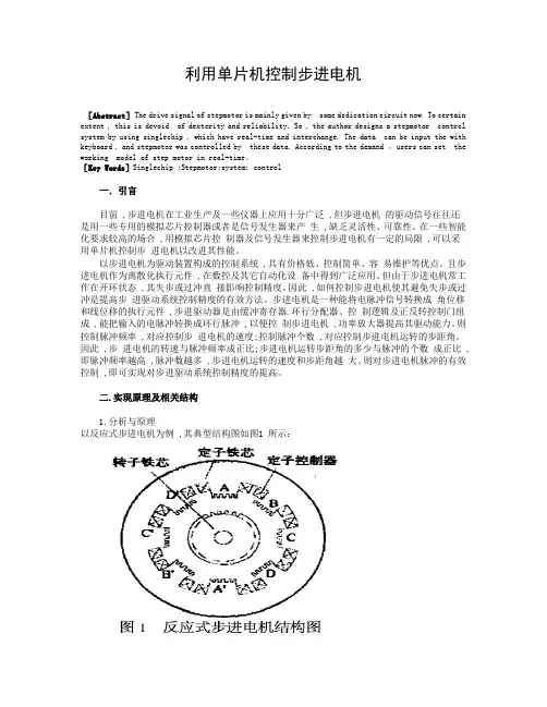
[Key Words]Singlechip ;Stepmotor;system;control一.引言目前 ,步进电机在工业生产及一些仪器上应用十分广泛 ,但步进电机的驱动信号往往还是用一些专用的模拟芯片控制器或者是信号发生器来产生 ,缺乏灵活性、可靠性。
在一些智能化要求较高的场合 ,用模拟芯片控制器及信号发生器来控制步进电机有一定的局限 ,可以采用单片机控制步进电机以改进其性能。
以步进电机为驱动装置构成的控制系统 ,具有价格低、控制简单、容易维护等优点。
且步进电机作为离散化执行元件 ,在数控及其它自动化设备中得到广泛应用。
但由于步进电机常工作在开环状态 ,其失步或过冲直接影响控制精度。
因此 ,如何控制步进电机使其避免失步或过冲是提高步进驱动系统控制精度的有效方法。
步进电机是一种能将电脉冲信号转换成角位移和线位移的执行元件 ,步进驱动器是由缓冲寄存器.环行分配器、控制逻辑及正反转控制门组成 ,能把输入的电脉冲转换成环行脉冲 ,以便控制步进电机 ,功率放大器提高其驱动能力。
单片机控制步进电机外文文献翻译单片机控制步进电机外文原文Stepping motor application and controlstepper motor is an electrical pulse will be converted into angular displacement of the implementing agencies. Put it in simple language-speaking: When the stepper drive pulse signal to a receiver, it drives stepper motor rotation direction by setting a fixed point of view (and the step angle). You can control the number of pulses to control the amount of angular displacement, so as to achieve the purpose of accurate positioning; At the same time, you can by controlling the pulsefrequency to control the motor rotation speed and acceleration, so as to achieve the purpose of speed.Stepper motor directly from the AC-DC power supply, and must use special equipment - stepper motor drive. Stepper motor drive system performance, in addition to their own performance with the motor on the outside, but also to a large extent depend on the drive is good or bad.A typical stepper motor drive system is operated by the stepper motor controller, stepper motor drives and stepper motor body is composed of three parts. Stepper motor controller stepper pulse and direction signal, each made of a pulse, stepper motor-driven stepper motor drives a rotor rotating step angle, that is, step-by-step further. High or low speed stepper motor, or speed, or deceleration, start or stop pulses areentirely dependent on whether the level or frequency. Decide the direction of the signal controller stepper motor clockwise or counterclockwise rotation. Typically, the stepper motor drive circuit from the logic control, power driver circuit, protection circuit and power components. Stepper motor drive controller, once received from the direction of the signal and step pulse, the control circuit on a pre-determined way of the electrical power-phase stepper motor excitation windings of the conduction or cut-off signal. Control circuit output signal power is low, can not provide the necessary stepping motor output power, the need for power amplifier, which is stepper motor driven power drive part. Power stepper motor drive circuit to control the input current winding to form a space for rotating magnetic field excitation, the rotor-driven movement. Protection circuit in the event of short circuit, overload, overheating, such as failure to stop the rapid drive and motor.Motor is usually for the permanent magnet rotor, when the current flows through the stator windings, the stator windings produce a magnetic field vector. The magnetic field will lead to a rotor angle of rotation, making a pair of rotor and stator magnetic field direction of the magnetic field direction. When the stator rotating magnetic field vector from a different angle. Also as the rotor magnetic field to a point of view. An electrical pulse for each input, the motor rotation angle step. Its output and input of the angular displacement is proportional to the pulses, with pulse frequency proportional to speed.Power to change the order of winding, the electrical will be reversed. We can, therefore, control the pulse number, frequency and electrical power windings of each phase to control the order of rotation of stepper motor.Stepper motor types:Permanent magnet (PM). Magnetic generally two-phase stepper, torque and are smaller and generally stepping angle of 7.5 degrees or 15 degrees; put more wind for air-conditioning.Reactive (VR), the domestic general called BF, have a common three-phase reaction, step angle of 1.5 degrees; also have five-phase reaction. Noise, no torque has been set at a large number of out.Hybrid (HB), common two-phase hybrid, five-phase hybrid, three-phase hybrid, four-phase hybrid, two-phase can be common with the four-phase drive, five-phase three-phase must be used with their drives;Two-phase, four-phase hybrid step angle is 1.8 degrees more than a small size, great distance, and low noise;Five-phase hybrid stepping motor is generally 0.72, the motor step angle small, high resolution, but the complexity of drive circuits,wiring problems, such as the 5-phase system of 10 lines.Three-phase hybrid stepping motor step angle of 1.2 degrees, but according to the use of 1.8 degrees, the three-phase hybrid stepping motor has a two-phase mixed than the five-phase hybrid more pole will help electric folder symmetric angle, it can be more than two-phase,five-phase high accuracy, the error even smaller, run moresmoothly.Stepper motor to maintain torque: stepper motor power means no rotation, the stator locked rotor torque. It is a stepper motor, one of the most important parameters, usually in the low-speed stepper motor torque at the time of close to maintain the torque. As the stepper motor output torque increases with the speed of constant attenuation, the output power also increases with the speed of change, so as to maintain torque on the stepper motor to measure the parameters of one of the most important. For example, when people say that the stepper motor 2N.m, in the absence of special circumstances that means for maintaining the torque of the stepper motor 2N.m.Precision stepper motors: stepper motor step angle accuracy of 3-5%, not cumulative.Stepper motor to allow the minimum amount of surfacetemperature:Steppermotor causes the motor temperature is too high the first magnetic demagnetization, resulting in loss of torque down even further, so the motor surface temperature should be the maximum allowed depending on the motor demagnetization of magnetic material points; Generally speaking, the magnetic demagnetization points are above 130 degrees Celsius, and some even as high as 200 degrees Celsius, so the stepper motor surface temperature of 80-90 degrees Celsius is normal.Start frequency of no-load: the stepper motor in case of no-load to the normal start of the pulse frequency, if the pulse frequency ishigher than the value of motor does not start, possible to lose steps or blocking. In the case of the load, start frequency should be lower. If you want to achieve high-speed rotation motor, pulse frequency should be to accelerate the process, that is, the lower frequency to start, and then rose to a certain acceleration of the desired frequency (motor speed from low rise to high-speed).Step angle: that is to send a pulse, the electrical angle corresponding to rotation.Torque positioning: positioning torque stepper motor does not refer to the case of electricity, locked rotor torque stator.Operating frequency: step-by-step stepper motor can run without losing thehighest frequency.Subdivision Drive: stepper motor drives the main aim is to weaken or eliminate low-frequency vibration of the stepper motor to improve the accuracy of the motor running. Reduce noise. If the step angle is 1.8 ? (full step) the two-phase hybrid stepping motor, if the breakdown of the breakdown of the number of drives for the 8, then the operation of the electrical pulse for each resolution of 0.072 ?, the precision of motor can reach or close to 0.225 ?, also depends on the breakdown of the breakdown of the drive current control accuracy and other factors, the breakdown of the number of the more difficult the greater the precision of control.How to determine the stepper motor driver DC power supply:A. Determination of the voltage: Hybrid stepping motor driver power supplyvoltage is generally a wide range (such as the IM483 supply voltage of 12 ~ 48VDC), the supply voltage is usually based on the work of the motor speed and response to the request to choose. If the motor operating speed higher or faster response to the request, then the voltage value is high, but note that the ripple voltage can not exceed the maximum input voltage of the drive, or it may damage the drive.B. Determination of CurrentPower supply current is generally based on the output phase current drive I to determine. If a linear power supply, power supply current is generally preferable 1.1 to 1.3 times the I; if we adopt the switching power supply, power supply current is generally preferable to I, 1.5 to 2.0 times.The main characteristics of stepping motor:1. A stepper motor drive can be added operate pulse drive signal must be no pulse when the stepper motor at rest, such as If adding the appropriate pulse signal, it will to a certain angle (called the step angle) rotation. Rotation speed and pulse frequency is proportional to.2. permanent magnet step angle stepper motor version is 7.5 degrees, 360 degrees around, takes 48 pulses to complete.3. stepper motor has instant start and rapid cessation of superior characteristics. Change the order of the pulse4(you can easily change the direction of rotation.Therefore, the current printers, plotters, robotics, and so devices are the core of the stepper motor as the driving force.Stepper motors have the following benefits: (1)Low cost(2)Ruggedness (3)Simplicity in construction (4)High reliability (5)No maintenance (6)Wideacceptance(7)No tweaking to stabilize (8)No feedback components are neededThey work in just about any environment Inherently more failsafethan servo motors. There isvirtually no conceivable failure within the stepper drive module that could cause the motor to run away. Stepper motors are simple to drive and control in an open-loop configuration. They only require four leads. They provide excellent torque at low speeds, up to 5 times the continuous torque of a brush motor of the same frame size or double the torque of the equivalent brushless motor. This often eliminates the need for a gearbox. A stepper-driven-system is inherently stiff, with known limits to the dynamic position error.Stepper Motor Disadvantages:Stepper motors have the following disadvantages:1. Resonance effects and relatively long settling times .2.Rough performance at low speed unless a microstep drive is used .3.Liability to undetected position loss as a result of operating open-loop .4. They consume current regardless of load conditions and therefore tend to run hot5. Losses at speed are relatively high and can cause excessive heating, and they are frequently noisy (especially at high speeds).6.They can exhibit lag-lead oscillation, which is difficult to damp.There is a limit to their available size, and positioning accuracy relies on the mechanics (e.g., ballscrew accuracy).Many of these drawbacks can be overcome by the use of a closed-loop control scheme.外文资料翻译译文步进电机应用和控制步进电机是将电脉冲转换成角位移的执行机构。
步进电机的的基本原理中英文翻译English translation of the stepping motor basic principle步进电机作为执行元件,是机电一体化的关键产品之一,广泛应用在各种自动化控制系统中。
随着微电子和计算机技术的发展,步进电机的需求量与日俱增,在各个国民经济领域都有应用。
The stepping motor as executing components, electromechanical integration is one of the key products, widely used in a variety of automatic control systems. With the development of microelectronics and computer technology, the stepper motor demand grow with each passing day, has been applied in various fields of the national economy.步进电机是一种将电脉冲转化为角位移的执行机构。
当步进驱动器接收到一个脉冲信号,它就驱动步进电机按设定的方向转动一个固定的角度(称为“步距角”),它的旋转是以固定的角度一步一步运行的。
可以通过控制脉冲个数来控制角位移量,从而达到准确定位的目的;同时可以通过控制脉冲频率来控制电机转动的速度和加速度,从而达到调速的目的。
步进电机可以作为一种控制用的特种电机,利用其没有积累误差(精度为100%)的特点,广泛应用于各种开环控制。
Stepping motor is a kind of electrical pulses into angular displacement of the implementing agencies. When stepping drive receives a pulse signal, it drives stepper motor rotate in the direction set by a fixed angle ( called the " step " ), it is the rotation at a fixed angle step by step operation. The number of pulses to control the amount of angular displacement through the control, so as to achieve the purpose of accurate positioning; also can control the pulse frequency to control motor rotation speed and acceleration, so as to achieve the purpose of speed. Special motor stepper motor control can be used as a, using its no accumulation of error ( accuracy of 100% ) characteristics, widely used in all kinds of open-loop control.现在比较常用的步进电机包括反应式步进电机(VR)、永磁式步进电机(PM)、混合式步进电机(HB)和单相式步进电机等。
Step Motor&Servo Motor Systems and ControlsMotion Architect® Software Does the Work for You... Configure ,Diagnose, Debug Compumotor’s Motion Architect is a Microsoft® Windows™-based software development tool for 6000Series products that allows you to automatically generate commented setup code, edit and execute motion control programs, and create a custom operator test panel. The heart of Motion Architect is the shell, which provides an integrated environment to access the following modules.• System Con figurator—This module prompts you to fill in all pertinent set-up information to initiate motion. Configurable to the specific 6000 Series product that is selected, the information is then used to generate actual 6000-language code that is the beginning of your program.• Program Editor—This module allows you to edit code. It also has the commands available through ―Help‖ menus. A user’s guide is provided on disk.• Terminal Emulator—This module allows you to interact directly with the 6000 product. ―Help‖ is again available with all commands and their definitions available for reference. • Test Panel—You can simulate your programs, debug programs, and check for program flow using this module.Motion Architect® has been designed for use with all 6000 Series products—for both servo and stepper technologies. The versatility of Windows and the 6000 Series language allow you to solve applications ranging from the very simple to the complex.Motion Architect comes standard with each of the 6000 Series products and is a tool that makes using these controllers even more simple—shortening the project development time considerably. A value-added feature of Motion Architect, when used with the 6000 Servo Controllers, is its tuning aide. This additional module allows you to graphically display a variety of move parameters and see how these parameters change based on tuning values.Using Motion Architect, you can open multiple windows at once. For example, both the Program Editor and Terminal Emulator windows can be opened to run the program, get information, and then make changes to the program.On-line help is available throughout Motion Architect, including interactive access to the contents of the Compumotor 6000 Series Software Reference Guide.SOLVING APPLICATIONS FROM SIMPLE TOCOMPLEXServo Control is Yours with Servo Tuner SoftwareCompumotor combines the 6000 Series servo controllers with Servo Tuner software. The Servo Tuner is an add-on module that expands and enhances the capabilities of Motion Architect®.Motion Architect and the Servo Tuner combine to provide graphical feedback ofreal-time motion information and provide an easy environment for setting tuning gains and related systemparameters as well as providing file operations to save and recall tuning sessions.Draw Your Own Motion Control Solutions with Motion Toolbox Software Motion Toolbox™ is an extensive library of LabVIEW® virtual instruments (VIs) for icon-based programming of Compumotor’s 6000 Series motion controllers.When using Motion Toolbox with LabVIEW, programming of the 6000 Series controller is accomplished by linking graphic icons, or VIs, together to form a block diagram. Motion Toolbox’s has a library of more than 150 command,status, and example VIs. All command and status VIs include LabVIEW source diagrams so you can modify them, if necessary, to suit your particular needs. Motion Toolbox als user manual to help you gut up and running quickly.comprehensiveM Software for Computer-Aided Motion Applications CompuCAM is a Windows-based programming package that imports geometry from CAD programs, plotter files, or NC programs and generates 6000 code compatible with Compumotor’s 6000 Series motion controllers. Available for purchase from Compumotor, CompuCAM is an add-on module which is invoked as a utility from the menu bar of Motion Architect.From CompuCAM, run your CAD software package. Once a drawing is created, save it as either a DXF file, HP-GL plot file or G-code NC program. This geometry is then imported into CompuCAM where the 6000 code is generated. After generating the program, you may use Motion Architect functions such as editing or downloading the code for execution.Motion Builder Software for Easy Programming of the 6000 SeriesMotion Builder revolutionizes motion control programming. This innovative software allows programmers to program in a way they are familiar with—a flowchart-style method. Motion Builder decreases the learning curve and makes motion control programming easy.Motion Builder is a Microsoft Windows-based graphical development environment which allows expert and novice programmers to easily program the 6000 Series products without learning a new programming language. Simply drag and drop visual icons that represent the motion functions you want to perform.Motion Builder is a complete application development environment. In addition to visually programming the 6000 Series products, users may configure, debug, download, and execute the motion program.SERVO VERSUS STEPPER... WHAT YOU NEED TOKNOWMotor Types and Their ApplicationsThe following section will give you some idea of the applications that are particularly appropriate for each motor type, together with certain applications that are best avoided. It should be stressed that there is a wide range of applications which can be equally well met by more than one motor type, and the choice will tend to be dictated by customer preference, previous experience or compatibility with existing equipment.A helpful tool for selecting the proper motor for your applicat ion is Compumotor’s Motor Sizing and Selection software package. Using this software, users can easily identify the appropriate motor size and type.High torque, low speedcontinuous duty applications are appropriate to the step motor. At low speeds it is very efficient in terms of torque output relative to both size and input power. Microstepping can be used to improve smoothness in lowspeed applications such as a metering pump drive for very accurate flow control.High torque, high speedcontinuous duty applications suit the servo motor, and in fact a step motor should be avoided in such applications because the high-speed losses can cause excessive motor heating.Short, rapid, repetitive movesare the natural domain of the stepper due to its high torque at low speeds, goodtorque-to-inertia ratio and lack of commutation problems. The brushes of the DC motor can limit its potential for frequent starts, stops and direction changes.Low speed, high smoothness application sare appropriate for microstepping or direct drive servos.Applications in hazardous environmentsor in a vacuum may not be able to use a brushed motor. Either a stepper or a brushless motor is called for, depending on the demands of the load. Bear in mind that heat dissipation may be a problem in a vacuum when the loads are excessive. SELECTING THE MOTOR THAT SUITS YOUR APPLICATION IntroductionMotion control, in its widest sense, could relate to anything from a welding robot to the hydraulic system in a mobile crane. In the field of Electronic Motion Control, we are primarily concerned with systems falling within a limited power range, typically up to about 10HP (7KW), and requiring precision in one or more aspects. This may involve accurate control of distance or speed, very often both, and sometimes other parameters such as torque or acceleration rate. In the case of the two examples given, the weldingrobot requires precise control of both speed and distance; the crane hydraulic system uses the driver as the feedback system so its accuracy varies with the skill of the operator. This wouldn’t be considered a motion control system in the strict sense of the term.Our standard motion control system consists of three basic elements:Fig. 1 Elements of motion control systemThe motor. This may be a stepper motor (either rotary or linear), a DC brush motor or a brushless servo motor. The motor needs to be fitted with some kind of feedback device unless it is a stepper motor.Fig. 2 shows a system complete with feedback to control motor speed. Such a system is known as a closed-loop velocity servo system.Fig. 2 Typical closed loop (velocity) servo systemThe drive. This is an electronic power amplifier thatdelivers the power to operate the motor in response to low-level control signals. In general, the drive will be specifically designed to operate with a particular motor type –you can’t use a stepper drive to operate a DC brush motor, for instance.Application Areas of Motor TypesStepper MotorsStepper Motor BenefitsStepper motors have the following benefits:• Low cost• Ruggedness• Simplicity in construction• High reliability• No maintenance• Wide acceptance• No tweaking to stabilize• No feedback components are needed• They work in just about any environment• Inherently more failsafe than servo motors.There is virtually no conceivable failure within the stepper drive module that could cause the motor to run away. Stepper motors are simple to drive and control in an open-loop configuration. They only require four leads. They provide excellent torque at low speeds, up to 5 times the continuous torque of a brush motor of the same frame size or double the torque of the equivalent brushless motor. This often eliminates the need for a gearbox. A stepper-driven-system is inherently stiff, with known limits to the dynamic position error.Stepper Motor DisadvantagesStepper motors have the following disadvantages:• Resonance effects and relatively long settlingtimes• Rough performance at low speed unless amicrostep drive is used• Liability to undetected position loss as a result ofoperating open-loop• They consume current regardless of loadconditions and therefore tend to run hot• Losses at speed are relatively high and can causeexcessive heating, and they are frequently noisy(especially at high speeds).• They can exhibit lag-lead oscillation, which isdifficult to damp. There is a limit to their availablesize, and positioning accuracy relies on themechanics (e.g., ballscrew accuracy). Many ofthese drawbacks can be overcome by the use ofa closed-loop control scheme.Note: The Compumotor Zeta Series minimizes orreduces many of these different stepper motor disadvantages.There are three main stepper motor types:• Permanent Magnet (P.M.) Motors• Variable Reluctance (V.R.) Motors• Hybrid MotorsWhen the motor is driven in its full-step mode, energizing two windings or ―phases‖ at a time (see Fig. 1.8), the torque available on each step will be the same (subject to very small variations in the motor and drive characteristics). In the half-step mode, we are alternately energizing two phases and then only one as shown in Fig. 1.9. Assuming the drive delivers the same winding current in each case, this will cause greater torque to be produced when there are two windings energized. In other words, alternate steps will be strong and weak. This does not represent a major deterrent to motor performance—the available torque is obviously limited by the weaker step, but there will be a significant improvement in low-speed smoothness over the full-step mode.Clearly, we would like to produce approximately equal torque on every step, and thistorque should be at the level of the stronger step. We can achieve this by using a higher current level when there is only one winding energized. This does not over dissipate the motor because the manufacturer’s current rating assumes two phases to be energized the current rating is based on the allowable case temperature). With only one phase energized, the same total power will be dissipated if the current is increased by 40%. Using this higher current in the one-phase-on state produces approximately equal torque on alternate steps (see Fig. 1.10).Fig. 1.8 Full step current, 2-phase onFig. 1.9 Half step currentFig. 1.10 Half step current, profiledWe have seen that energizing both phases with equal currents produces an intermediate step position half-way between the one-phase-on positions. If the two phase currents are unequal, the rotor position will be shifted towards the stronger pole. This effect is utilized in the microstepping drive, which subdivides the basic motor step by proportioning thecurrent in the two windings. In this way, the step size is reduced and the low-speed smoothness is dramatically improved. High-resolution microstep drives divide the full motor step into as many as 500 microsteps, giving 100,000 steps per revolution. In this situation, the current pattern in the windings closely resembles two sine waves with a 90°phase shift between them (see Fig. 1.11). The motor is now being driven very much as though it is a conventional AC synchronous motor. In fact, the stepper motor can be driven in this way from a 60 Hz-US (50Hz-Europe) sine wave source by including a capacitor in series with one phase. It will rotate at 72 rpm.Fig. 1.11 Phase currents in microstep modeStandard 200-Step Hybrid MotorThe standard stepper motor operates in the same way as our simple model, but has a greater number of teeth on the rotor and stator, giving a smaller basic step size. The rotor is in two sections as before, but has 50 teeth on each section. The half-tooth displacement between the two sections is retained. The stator has 8 poles each with 5 teeth, making a total of 40 teeth (see Fig. 1.12).Fig. 1.12 200-step hybrid motorIf we imagine that a tooth is placed in each of the gaps between the stator poles, there would be a total of 48 teeth, two less than the number of rotor teeth. So if rotor and stator teeth are aligned at 12 o’clock, they will also be aligned at 6 o’clock. At 3 o’clock and 9 o’clock the teeth will be misaligned. However, due to the displacement between the sets of rotor teeth, alignment will occur at 3 o’clock and 9 o’clock at the other end of the rotor.The windings are arranged in sets of four, and wound such that diametrically-oppositepoles are the same. So referring to Fig. 1.12, the north poles at 12 and 6 o’clock attract the south-pole teeth at the front of the rotor; the south poles at 3 and 9 o’clock attract the north-pole teeth at the back. By switching current to the second set of coils, the stator field pattern rotates through 45°. However, to align with this new field, the rotor only has to turn through 1.8°. This is equivalent to one quarter of a tooth pitch on the rotor, giving 200 full steps per revolution.Note that there are as many detent positions as there are full steps per rev, normally 200. The detent positions correspond with rotor teeth being fully aligned with stator teeth. When power is applied to a stepper drive, it is usual for it to energize in the ―zero phase‖ state in which there is current in both sets of windings. The resulting rotor position does not correspond with a natural detent position, so an unloaded motor will always move by at least one half step at power-on. Of course, if the system was turned off other than in the zero phase state, or the motor is moved in the meantime, a greater movement may be seen at power-up.Another point to remember is that for a given current pattern in the windings, there are as many stable positions as there are rotor teeth (50 for a 200-step motor). If a motor isde-synchronized, the resulting positional error will always be a whole number of rotor teeth or a multiple of 7.2°. A motor cannot ―miss‖ individual steps – position errors of one or two steps must be due to noise, spurious step pulses or a controller fault.Fig. 2.19 Digital servo driveDigital Servo Drive OperationFig. 2.19 shows the components of a digital drive for a servo motor. All the main control functions are carried out by the microprocessor, which drives a D-to-A convertor to produce an analog torque demand signal. From this point on, the drive is very much like an analog servo amplifier.Feedback information is derived from an encoder attached to the motor shaft. The encoder generates a pulse stream from which the processor can determine the distance travelled, and by calculating the pulse frequency it is possible to measure velocity.The digital drive performs the same operations as its analog counterpart, but does so by solving a series of equations. The microprocessor is programmed with a mathematical model (or ―algorithm‖) of the equivalent analog system. This model predicts the behavior of the system. In response to a given input demand and output position. It also takes into account additional information like the output velocity, the rate of change of the input and the various tuning settings.To solve all the equations takes a finite amount of time, even with a fast processor – this time is typically between 100ms and 2ms. During this time, the torque demand must remain constant at its previously-calculated value and there will be no response to a change at the input or output. This ―update time‖ therefore becomes a critical factor in the performance of a digital servo and in a high-performance system it must be kept to a minimum.The tuning of a digital servo is performed either by pushbuttons or by sending numerical data from a computer or terminal. No potentiometer adjustments are involved. The tuning data is used to set various coefficients in the servo algorithm and hence determines the behavior of the system. Even if the tuning is carried out using pushbuttons, the final values can be uploaded to a terminal to allow easy repetition.In some applications, the load inertia varies between wide limits – think of an arm robot that starts off unloaded and later carries a heavy load at full extension. The change in inertia may well be a factor of 20 or more, and such a change requires that the drive isre-tuned to maintain stable performance. This is simply achieved by sending the new tuning values at the appropriate point in the operating cycle.步进电机和伺服电机的系统控制运动的控制者---软件:只要有了软件,它可以帮助我们配置改装、诊断故障、调试程序等。
毕业设计(论文)外文资料翻译学院:机械工程学院专业:机械设计制造及其自动化姓名:张XX学号:XXXXXXXXXX外文出处:《Computational Intelligence and (用外文写)Design》附件: 1.外文资料翻译译文;2.外文原文。
注:请将该封面与附件装订成册。
附件1:外文资料翻译译文基于微型计算机的步进电机控制系统设计孟天星余兰兰山东理工大学电子与电气工程学院山东省淄博市摘要本文详细地介绍了一种以AT89C51为核心的步进电机控制系统。
该系统设计包括硬件设计、软件设计和电路设计。
电路设计模块包括键盘输入模块、LED显示模块、发光二极管状态显示和报警模块。
按键可以输入设定步进电机的启停、转速、转向,改变转速、转向等的状态参数。
通过键盘输入的状态参数来控制步进电机的步进位置和步进速度进而驱动负载执行预订的工作。
运用显示电路来显示步进电机的输入数据和运行状态。
AT89C51单片机通过指令系统和编译程序来执行软件部分。
通过反馈检测模块,该系统可以很好地完成上述功能。
关键词:步进电机,AT89C51单片机,驱动器,速度控制1概述步进电机因为具有较高的精度而被广泛地应用于运动控制系统,例如机器人、打印机、软盘驱动机、绘图仪、机械式阀体等等。
过去传统的步进电机控制电路和驱动电路设计方法通常都极为复杂,由成本很高而且实用性很差的电器元件组成。
结合微型计算机技术和软件编程技术的设计方法成功地避免了设计大量复杂的电路,降低了使用元件的成本,使步进电机的应用更广泛更灵活。
本文步进电机控制系统是基于AT89C51单片机进行设计的,它具有电路简单、结构紧凑的特点,能进行加减速,转向和角度控制。
它仅仅需要修改控制程序就可以对各种不同型号的步进电机进行控制而不需要改变硬件电路,所以它具有很广泛的应用领域。
2设计方案该系统以AT89C51单片机为核心来控制步进电机。
电路设计包括键盘输入电路、LED显示电路、发光二极管显示电路和报警电路,系统原理框图如图1所示。
中文1597字Step of electric machine universal controller realizes whichbased on the MSP430F149 Single Chip Microcomputer.Abstract:With the infiltration in the social field of the computer in recent years, the application of the one-chip computer is moving towards deepening constantly, drive tradition is itmeasure crescent benefit to upgrade day to control at the same time. In measuring in real time andautomatically controlled one-chip computer application system, the one-chip computer often usesas a key part, only one-chip computer respect knowledge is not enough, should also follow thestructure of the concrete hardware , and direct against and use the software of target'scharacteristic to combine concretely, in order to do perfectly.This article mainly introduced realizes a step of machine universal controller based on the MSP430F149 monolithic integrated circuit. This controller may simultaneously control the multi-tablecloths machine according to the curve way movement, including adds and subtracts fast, the localization and the commutation function and so on. In the article discussed with emphasis step machine has risen to low the speed and the curve design proposal and its the realization method.1. a preface:based on the step of machine control system, except step machine generally also needs the special actuation power source, actuates the power source merely to complete the power actuation part, the user certainly cannot cause the entire control system according to prearrange, the expectation active status movement, must control to its actuation power source, the user needs to develop once more.In view of this, has designed a step of machine universal controller which realizes based onthe MSP430F149 monolithic integrated circuit, may satisfy the majority controllingfield originally request. The controller main function is:(1) May control the multi- wraps step of machine actuation system; At present may simultaneously control 3 sets of systems.(2) work way is flexible, may according to the hypothesis curve movement, the curve most reach 8 sections; May according to the control signal movement which exterior examines; May according to the simulation adjustment test function movement;2. Systems designs2.1 systems structureThis controller has mainly realized thematic- tablecloths machine in the multistage curve operating control.2.2 microprocessors choiceThis design has selected MSP which Incorporation produces series monolithic integrated circuit MSP430F149.The goal is applies its rich connection resources and the formidable timer function, the MSP430F149 performance characteristic as follows:(1) 6 eight bit parallel connections; Definitely may realize this system all signals input, the output, does not need the hardware to expand, P1, the P2 eight bit parallel ports each mouth line all has the severance function, softly causes the keyboard, the hardware design to change is extremely simple.(2) 12 A/D switch ADC; Completes the simulation hypothesis function.(3) Formidable timer function; TIMER-A3, TIMER-B7 respectively be have3 and 7 captures/compares the register 16 timers, may satisfy the system speed the hypothesis and the curve fixed time request.(4)Liquid crystal actuation module;(5) In sets at 2KB RAM, 60KB FLASH;MSP430F149 provides the rich resources, the periphery hardware expands only must do the very few work, not only designs changes extremely imply, and moreover this controller volume small, the reliability is high.2.3 steps of machine starting and add/decelerate the control planThe step of motive highest starting frequency (step frequency) generally is 0.1KHz arrives 3-4KHz, but the highest movement frequency may achieve N*102 KHz. Surpasses the highest starting frequency the frequency direct-on starting, will appear\" Falls out of step \" Phenomenon, even is unable to start.The more ideal starting curve should be according to the index rule starting. But the practical application to starts the section processing to be possible to use according to the fitting a straight Line method, namely \" Steps and ladders law \”. May according to two kind of situations processing, (1) known frequency press the frequency partition to start, the partition counts n=f/f q.(2) Unknown frequency, then to assigns according to the section. Uses \" Steps and ladders law \" Continuously raises the speed the speed which needs, then locking, according to pre-placed curve movement. Fitting the starting frequency, after each section of frequencies hand over the increase (to call steps and ladders frequency) △f=f/8, namely uses 8 sections of fitting. In the operating control process, (frequency) divides into the outset speed n minute achievement steps and ladders frequency, When 2.4 steps of machine commutation questions step of machine commutation, certainly must stop in the electrical machinery or fall commutates again to the frequency range in, in order to avoid has a bigger impact to damage the electrical machinery. The commutation signal certainly must last the CP pulse finish after the preceding direction as well as in front of the next direction first CP pulse sends out.2.4 steps of machine commutation questionsStep of machine commutation, certainly must stop in the electrical machinery or fall commutates again to the frequency range in, in order to avoid has a bigger impact to damage theelectrical machinery. The commutation signal certainly must last the CP pulse finish after the preceding direction as well as in front of the next direction first CP pulse sent out in some high speed under, the reverse cut essence has contained -> the commutation -> three processes2.5 speeds and the timer starting value transformationThis system speed control is the dependence fixed time produces; the hypothesis speed which the CP pulse completes with has the CP pulse timer starting value to have the certain relations. The MSP430F149 timer work way has many kinds of, this design timer work under continual way. In the continual pattern, the timer starts from its current value to count, after counts to 0FFFFH from \" 0\" Starts redo count. Under this way, compares the timer current value and comparison register CCRX, if equal has the severance, and May the time which has the next event add to in this interrupt service is on comparison register CCRX.Fixed time the starting value = must fixed time the value/count the cycle; Often assigns regarding the step of machine its speed value by the frequency form, such as movement under 20KHZ, therefore the previous type may transform is: Fixed time the starting value = counts the frequency/speed value. (Counts frequency for system clock frequency)3. ConcludingRemark this controller may realize step machine under the multistage hypothesis curve operating control, has the hardware simply, the reliable high characteristic, has used in on the electric wire production line platoon line control section it, has obtained the satisfying effect. This topic funds the project for the north industry big school scientific research foundation.译文译文基于MSP430F149单片机实现的步进电机通用控制器摘要:近年来随着计算机在社会领域的渗透, 单片机的应用正在不断地走向深入,同时带动传统控制检测日新月益更新。
步进电机运动控制系统外文文献翻译中英文外文文献翻译(含:英文原文及中文译文)文献出处:YH Lee. Stepper motor motion control system design [J]. Equipment Manufacturing Technology, 2015,2(6):31-41.英文原文Stepper motor motion control system designYH LeeAbstractStepper motors are open-loop control elements that convertelectrical pulse signals to angular or linear displacements. In the case of non-overload, the rotation speed and stop position of the motor depend only on the frequency and pulse number of the pulse signal, and is not affected by the load change, that is, a pulse signal is applied to the motor, and the motor rotates through a step angle. The existence of this linear relationship, coupled with the fact that the stepper motor has only periodic errors and no cumulative errors, is a feature. It is very simple to use a stepper motor to control the speed and position. Stepper motor speed control is generally to change the frequency of the input stepper motor pulse to achieve stepper motor speed control, because the stepper motor for each pulse to rotate afixed angle, so that you can control the stepper motor The time intervalfrom one pulse to the next pulse changes the frequency of the pulse. The length of the delay controls the step anglespecifically to change the rotation speed of the motor, thereby realizing the stepping motor speed control. In this design scheme, the internal timer of the AT89C51 microcontroller is used to change the frequency of the CP pulse to realize the control of the rotation speedof the stepper motor to realize the functions of the motor speed adjustment and forward and reverse rotation. The design takes into consideration that the CPU may be disturbed when executing instructions, causing the program to "run away" or enter the "endless loop". Therefore, the watchdog circuit is designed using a microprocessing system monitoring integrated chip manufactured by MAXIM. MAXI813. This article also gives the related hardware block diagram and software flow chart in detail, and has compiled the assembly language program.Keywords: stepper motor single chip microcomputer speed control systemIntroductionStepper motors were first developed by the British in 1920. The invention of the transistor in the late 1950s was also gradually applied to a stepping motor, which made it easier to control the digitization. After continuous improvement, today's stepper motors have been widely used in mechanical systems with high controllability such as high positioning accuracy, high decomposition performance, highresponsiveness, and reliability. In the production process, where automation, labor saving, andhigh efficiency are required, we can easily find traces of stepper motors, especially those that emphasize speed, position control, and flexible control applications that require precise command operation. The most. As an actuator, a stepper motor is one of the key products of electromechanical integration and is widely used in various automation control systems. With the development of microelectronics and computer technology, the demand for stepper motors is increasing day by day, and there are applications in various national economic fields. A stepper motor is an actuator that converts an electrical pulse signal into an angular or linear displacement. Stepper motors can be driven directly with digital signals and are very easy to use. The general motor is continuous rotation, while the stepper motor has two basic states of positioning and operation. When there is a pulse input, the stepping motor rotates step by step, and when it is given a pulse signal, it turns a certain angle. The angular displacement of the stepping motor is strictly proportional to the number of input pulses and is synchronized in time with the input pulse. Therefore, as long as the number of input pulses, the frequency, and the phase sequence of the motor windings are controlled, the desired rotation angle can be obtained. Speed and direction of rotation. When there is no pulse input, the air gap magnetic field can keep the rotor in the original position under theexcitation of the winding power supply. So it is very suitable forsingle chip microcomputer control. Stepper motors also have features such as fast start, precise stepping and positioning, and are thus widely used in CNC machine tools, plotters, printers, and optical instruments. Stepping motors have become the third category of motors except for DC motors and AC motors. Traditional electric motors, as electromechanical energy conversion devices, play a key role in human production and life into the electrification process. The stepper motor can be used as a special motor for control, and it is widely used in various open-loop control because it has no accumulated error (accuracy is 100%). Now more commonly used stepper motors include reactive stepper motors (VR), permanent magnet stepper motors (PM), hybrid stepper motors (HB), and single-phase stepper motors. Permanent-magnet type stepping motor is generally two-phase, small torque and volume, step angle is generally 7.5 degrees or 15 degrees; Reactive stepping motor is generally three-phase, can achieve large torque output, stepping The angle is generally 1.5 degrees, but the noise and vibration are large. The rotor of the reactive stepper motor is magnetically routed from a soft magnetic material, and the stator has a multi-phase excitation winding, which generates torque using a change in the magnetic permeability. Hybrid stepping motor refers to the advantage of mixing permanent magnet type and reactive type. It is divided into two phases and five phases: the two-phase step angle is generally 1.8 degrees andthe five-phase step angle is generally 0.72 degrees. This type of steppermotor is the most widely used and is also the stepper motor used in this subdivision drive scheme.1 stepper motor overview1. 1 stepper motor features:1) The accuracy of a typical stepper motor is 3-5% of the step angle and does not accumulate. 2) The allowable temperature of the stepper motor is high. Excessively high temperature of the stepping motor first demagnetizes the magnetic material of the motor, resulting in a drop in torque and even loss of synchronism. Therefore, the maximum temperature allowed for the appearance of the motor should depend on the demagnetization point of the magnetic material of different motors; generally, the demagnetization of the magnetic material. The points are all above 130 degrees Celsius, and some are even up to 200 degrees Celsius. Therefore, the external temperature of the stepper motor is completely normal at 80-90 degrees Celsius. 3) The torque of the stepper motor will decrease as the rotation speed increases. When the stepper motor rotates, the inductance of each phase winding of the motor will form a counter electromotive force; the higher the frequency, the greater the counter electromotive force. Under its effect, the motor's phase current decreases as the frequency (or speed) increases, causing the torque to drop. 4) The stepping motor can run normally at low speed,but it cannot start if it is higher than a certain speed, accompanied by howling. The stepper motorhas a technical parameter: No-load starting frequency, that is the pulse frequency that the stepping motor can start normally under no-load conditions. If the pulse frequency is higher than this value, the motor cannot start normally, and step loss or stall may occur. In the case of load, the starting frequency should be lower. If the motor is to be rotated at a high speed, the pulse frequency should have an acceleration process, that is, the starting frequency is low, and then it is increased to a desired high frequency (motor speed is raised from low speed to high speed) at a certain acceleration. TC \* MERGEFORMAT1. 2 working principle of stepping motorA stepper motor is a type of motor that is controlled by anelectrical pulse and converts the electrical pulse signal into a phase-shifted motor whose mechanical displacement and rotational speed are proportional to the number of pulses and the pulse frequency of the input motor winding. Each pulse signal can be stepped The feed motor rotates at a fixed angle. The number of pulses determines the total angle of rotation. The frequency of the pulse determines the speed of the motor. When the stepper receives a pulse signal, it drives the stepper motor to rotate in the set direction. At a fixed angle (called "step angle"), its rotation is performed step by step at a fixed angle. By controlling the number of pulses to control the angular displacement,so as to achieve the purpose of accurate positioning; At the same time, by controlling the pulse frequencyto control the speed and acceleration of the motor rotation, so asto achieve the purpose of speed control.2 Basic requirements for designStudy the characteristics, working principle, and specific speed regulation principle of stepper motor. TC \* MERGEFORMATBasic requirements The stepper motor uses a three-phase steppermotor with a power of 1W. When the speed is in the range of 0 to1000r/min, the maximum accuracy is 2%. To basically complete the graduation design, the stepper motor can perform precise speed control, positive and negative rotation, and it can not lose step when starting. Basically, there is no Oscillation, can complete the complete hardware circuit diagram, software design.3 Argumentation of the plan3.1 Determination of control methodsAlthough the stepper motor control is a relatively accurate, open-loop stepper motor control system has the advantages of low cost, simple, convenient control, etc., in the open-loop system of the stepper motor using the microcontroller, the frequency of the CP pulse of the control system or change The cycle is actually controlling the speed of the stepper motor. There are two ways the system can achieve stepper motor speed control. One is delay, the other is timing. The delay method is to call a delay subroutine after each commutation. After the delay isover, the commutation is executed again. In this way, CP pulses or commutation cycles with a certain frequency can be issued. The delay time of the delay subroutine and the time used by the commutation program are the cycles of the CP pulse. This method is simple, uses less resources, and is implemented by software. Different subroutines can be called to achieve different speeds. However, it takes a long time to process the CPU and cannot handle other tasks at runtime. Therefore, it is only suitable for a simpler control process. The timing method is to use the timer timing function in the microcontroller system to generate an arbitrary period of the timing signal, so that the period of the system output CP pulse can be conveniently controlled. When the timer is started, the timer counts up the system and its cycle starting from the loaded initial value. When the timer overflows, the timer generates an interrupt and the system transfers to execute the timer interrupt subroutine. The motor commutation subroutine is placed in the timer interrupt service routine. The timer interrupt is once and the motor is reversed once to achieve motor speed control. Since there is a certain time interval from the start of restarting the timer to the timer application interruption, the timing time is increased. In order to reduce this timing error and achieve accurate timing, it is necessary to make appropriate adjustments to the initial value of reloading counts. . The initial value of adjusted reloading mainly considers two factors and one is the time required to interrupt theresponse. The second is the time occupied by reloading the initial value instruction, including other instructions that interrupt the service program before reloading the initial value. After these two factors are combined, the correction amount of the reload count initial value takes 8 machine cycles, that is, the timing time is shortened by 8 machine cycles. When using the timer interrupt to control the motor shift, it is actually changing the size of the timer load value. In the control process, a discrete approach is used to approximate the ideal speed curve. In order to reduce the time for calculating the load value in each step, the load value required for the speed of each discrete point is fixed in the ROM of the system when the system is designed. The system uses the table look-up method to find the required load value in the system. Significantly reduce the time spent on CPU and improve the response speed of the system. Most stepper motor motion control systems are designed to run in an open-loop state, because the cost is low, and the position control inherent in the motion control technology can be provided without feedback. However, in some applications, more reliability, security, or product quality assurance is required. Therefore, closed-loop control is also an option. Here are some methods for achieving closed-loop control of stepper motors: 1) Step-by-step confirmation, This is the simplest displacement control, using a low-value optical encoder to calculate the amount of step movement. A simple loop compares the stepper motor with the commandverification and verifies that the stepper motor moves to the expected position; 2) Back-EMF, a sensorless detection method, uses a stepper motor's back EMF (eleCtromotiveCe, emf) signal , Measure and control speed. When the back-EMF voltage drops to the monitoring detection level, the closed-loop control is changed to the standard open-loop to complete the final displacement movement; 3) Full-servo control refers to the full-time use of feedback devices for stepper motors - encoders, decoding , or other feedback sensors to more accurately control the stepper motor displacement and torque. Other methods include a variety of different back-EMF control motor parameter measurements and software techniques that some manufacturers use. Here, the stepper drive monitors and measures the motor coils and uses voltage current information to increase the stepper motor control. Positive damping uses this information to block the speed of vibration, producing more usable torque output and reducing torque-induced mechanical vibration losses. No encoder installation monitoring uses information to detect the loss of synchronous speed. Conventional stepper motor control usually employs feedback devices and non-sensing methods, and is an effective method to implement a sports application with safety requirements, dangerous conditions or high accuracy requirements. Most stepper motor-based systems typically operate in an open-loop state, which provides a low-cost solution. In fact, stepper systems can improve the performanceof displacement control without feedback. However, when the stepper motor is running in open loop, there may be a simultaneous loss between the command pace and the actual step. Closed-loop control, which is part of traditional step control, can effectively provide higher reliability, safety, or product quality. In these stepper systems, the closed loop of the feedback device or indirect parametric sensing method can correct or control out-of-step, monitor motor stagnation, and ensure greater available torque output. Recently, closed-loop control (CLC) of stepper motors can also help implement smart distributed motion architectures. However, there is a risk of out-of-step operation in open-loop operation, which will result in positioning errors. However, compared to encoders used in servo systems, closed-loop stepper motors use encoders that are less costly. Therefore, closed-loop control is selected.3.2 Determination of Drive ModeThere are generally two methods for driving a stepping motor. One is directly driven by the CPU. This method is generally not suitable because the output current pulse of the CPU is extremely small and it cannot sufficiently rotate the stepping motor. One is indirect drivingby the CPU, which is to amplify the signal output from the CPU, and then directly drive or indirectly drive the stepper motor throughphotoelectric isolation. This method is relatively safe and reliable. The solid design should use a CPU to drive the stepper motor indirectly. Thetachogenerator of the encoder is also used as the speed measurement tool. Because the closed-loop control is selected, there must be feedback components. There are generally two types of feedback components. One is the coaxial tachometer generator, and the speed of the stepping motor is fed back. Back, and then through the display and stepper motor adjustment; Another is through the optical coaxial encoder to the stepper motor speed feedback back to the stepper motor to adjust; compared to the latter, the latter The design is relatively simple, inexpensive, safe and reliable, and less polluting. The latter is generally used for solids, and photoelectric crumblers are used as feedback components.3. 3 Selection of Drive CircuitThere are many kinds of driving motors for stepping motors, but the most common ones are single voltage driving, dual voltage driving, chopper driving, subdivision control driving and so on. Single-voltage driving is the simplest driving circuit in stepper motor control. It is essentially a single-phase inverter. Its greatest feature is its simple structure, because of its low work efficiency, especially its prominent features at high frequencies. Its external resistor R consumes a considerable amount of heat, which affects the stability of the circuit. This type of drive is generally used only in the drive circuit of a low-power stepper motor. Dual-voltage driving is generally driven by two power supply voltages. Since these two power supplies are one highvoltage and one low voltage, they are also called high and low voltage driving circuits. The disadvantage of the dual-voltage driving circuit is that the valley point appears in the current at the high-low voltage connection, which inevitably causes the torque to drop at the valley point. Not suitable for normal operation of the motor. For the chopper circuit drive, this disadvantage can be overcome and the efficiency of the stepper motor can also be improved. Therefore, it is a good driver circuit from the standpoint of improving efficiency. It can use a higher power supply voltage and does not require an external resistor to limit the rated current and reduce the time constant. However, due to the sawtooth fluctuations at the top of the waveform, large electromagnetic noise is generated. The subdivision drive is powered by a pulse voltage. For a voltage pulse, the rotor can rotate one step. Generally, according to the voltage pulse distribution method, each phase winding of the stepping motor will alternately switch, and the rotor of the stepping motor can be fixed. Rotate. The subdivided control circuit is generally divided into two types. One is to use a linear analog power amplifier to obtain a staircase current. This method is simple but inefficient. The other method is to use a single-chip microcomputer to obtain the step current by using the method of pulse width modulation. This method requires complex calculations to make the substepped step angles uniform. However, due to the fact that the design of the stepper motor requires a relatively wide range ofhigh-speed adjustments, the drive chip 8713 should be used to drive themotor and the speed of the stepper motor must be controlled by software.中文译文步进电机运动控制系统设计作者:YH Lee摘要步进电机是将电脉冲信号转变为角位移或线位移的开环控制元件。
附录2:英文资料及其中文翻译Stepper motor is an electrical pulse will be converted into angular displacement of the implem enting agencies. Put it in simple language-speaking: When the stepper drive pulse signal to a r eceiver, it drives stepper motor rotation direction by setting a fixed point of view (and the ste p angle). You can control the number of pulses to control the amount of angular displacement, so as to achieve the purpose of accurate positioning; At the same time, you can by controllin g the pulse frequency to control the motor rotation speed and acceleration, so as to achieve th e purpose of speed.Stepper motor directly from the AC-DC power supply, and must use special equipment - stepp er motor drive. Stepper motor drive system performance, in addition to their own performance with the motor on the outside, but also to a large extent depend on the drive is good or bad.A typical stepper motor drive system is operated by the stepper motor controller, stepper mot or drives and stepper motor body is composed of three parts. Stepper motor controller stepper pulse and direction signal, each made of a pulse, stepper motor-driven stepper motor drives a rotor rotating step angle, that is, step-by-step further. High or low speed stepper motor, or spe ed, or deceleration, start or stop pulses are entirely dependent on whether the level or frequenc y. Decide the direction of the signal controller stepper motor clockwise or counterclockwise rot ation. Typically, the stepper motor drive circuit from the logic control, power driver circuit, pr otection circuit and power components. Stepper motor drive controller, once received from the direction of the signal and step pulse, the control circuit on a pre-determined way of the electr ical power-phase stepper motor excitation windings of the conduction or cut-off signal. Control circuit output signal power is low, can not provide the necessary stepping motor output powe r, the need for power amplifier, which is stepper motor driven power drive part. Power stepper motor drive circuit to control the input current winding to form a space for rotating magnetic field excitation, the rotor-driven movement. Protection circuit in the event of short circuit, ove rload, overheating, such as failure to stop the rapid drive and motor.Motor is usually for the permanent magnet rotor, when the current flows through the stator wi ndings, the stator windings produce a magnetic field vector. The magnetic field will lead to a rotor angle of rotation, making a pair of rotor and stator magnetic field direction of the magne tic field direction. When the stator rotating magnetic field vector from a different angle. Also as the rotor magnetic field to a point of view. An electrical pulse for each input, the motor r otation angle step. Its output and input of the angular displacement is proportional to the pulse s, with pulse frequency proportional to speed. Power to change the order of winding, the elect rical will be reversed. We can, therefore, control the pulse number, frequency and electrical po wer windings of each phase to control the order of rotation of stepper motor.Stepper motor types:Permanent magnet (PM). Magnetic generally two-phase stepper, torque and are smaller and gen erally stepping angle of 7.5 degrees or 15 degrees; put more wind for air-conditioning. Reactive (VR), the domestic general called BF, have a common three-phase reaction, step angl e of 1.5 degrees; also have five-phase reaction. Noise, no torque has been set at a large numb er of out.Hybrid (HB), common two-phase hybrid, five-phase hybrid, three-phase hybrid, four-phase hybri d, two-phase can be common with the four-phase drive, five-phase three-phase must be used w ith their drives;Two-phase, four-phase hybrid step angle is 1.8 degrees more than a small size, great distance, and low noise;Five-phase hybrid stepping motor is generally 0.72, the motor step angle small, high resolution, but the complexity of drive circuits, wiring problems, such as the 5-phase system of 10 lines. Three-phase hybrid stepping motor step angle of 1.2 degrees, but according to the use of 1.8 degrees, the three-phase hybrid stepping motor has a two-phase mixed than the five-phase hybr id more pole will help electric folder symmetric angle, it can be more than two-phase, five-ph ase high accuracy, the error even smaller, run more smoothly.Stepper motor to maintain torque: stepper motor power means no rotation, the stator locked rot or torque. It is a stepper motor, one of the most important parameters, usually in the low-spee d stepper motor torque at the time of close to maintain the torque. As the stepper motor outp ut torque increases with the speed of constant attenuation, the output power also increases with the speed of change, so as to maintain torque on the stepper motor to measure the parameter s of one of the most important. For example, when people say that the stepper motor 2N.m, i n the absence of special circumstances that means for maintaining the torque of the stepper m otor 2N.m.Precision stepper motors: stepper motor step angle accuracy of 3-5%, not cumulative.Start frequency of no-load: the stepper motor in case of no-load to the normal start of the pul se frequency, if the pulse frequency is higher than the value of motor does not start, possible to lose steps or blocking. In the case of the load, start frequency should be lower. If you wa nt to achieve high-speed rotation motor, pulse frequency should be to accelerate the process, th at is, the lower frequency to start, and then rose to a certain acceleration of the desired freque ncy (motor speed from low rise to high-speed).Step angle: that is to send a pulse, the electrical angle corresponding to rotation.Torque positioning: positioning torque stepper motor does not refer to the case of electricity, l ocked rotor torque stator.Operating frequency: step-by-step stepper motor can run without losing the highest frequency. Subdivision Drive: stepper motor drives the main aim is to weaken or eliminate low-frequency vibration of the stepper motor to improve the accuracy of the motor running. Reduce noise. I f the step angle is 1.8 °(full step) the two-phase hybrid stepping motor, if the breakdown of the breakdown of the number of drives for the 8, then the operation of the electrical pulse for each resolution of 0.072 °, the precision of motor can reach or close to 0.225 °, also depend s on the breakdown of the breakdown of the drive current control accuracy and other factors, the breakdown of the number of the more difficult the greater the precision of control.步进电机是一种将电脉冲转化为角位移的执行机构。