关于步进电机外文翻译
- 格式:doc
- 大小:306.00 KB
- 文档页数:15
附录2:英文资料及其中文翻译Stepper motor is an electrical pulse will be converted into angular displacement of the implem enting agencies. Put it in simple language-speaking: When the stepper drive pulse signal to a r eceiver, it drives stepper motor rotation direction by setting a fixed point of view (and the ste p angle). You can control the number of pulses to control the amount of angular displacement, so as to achieve the purpose of accurate positioning; At the same time, you can by controllin g the pulse frequency to control the motor rotation speed and acceleration, so as to achieve th e purpose of speed.Stepper motor directly from the AC-DC power supply, and must use special equipment - stepp er motor drive. Stepper motor drive system performance, in addition to their own performance with the motor on the outside, but also to a large extent depend on the drive is good or bad.A typical stepper motor drive system is operated by the stepper motor controller, stepper mot or drives and stepper motor body is composed of three parts. Stepper motor controller stepper pulse and direction signal, each made of a pulse, stepper motor-driven stepper motor drives a rotor rotating step angle, that is, step-by-step further. High or low speed stepper motor, or spe ed, or deceleration, start or stop pulses are entirely dependent on whether the level or frequenc y. Decide the direction of the signal controller stepper motor clockwise or counterclockwise rot ation. Typically, the stepper motor drive circuit from the logic control, power driver circuit, pr otection circuit and power components. Stepper motor drive controller, once received from the direction of the signal and step pulse, the control circuit on a pre-determined way of the electr ical power-phase stepper motor excitation windings of the conduction or cut-off signal. Control circuit output signal power is low, can not provide the necessary stepping motor output powe r, the need for power amplifier, which is stepper motor driven power drive part. Power stepper motor drive circuit to control the input current winding to form a space for rotating magnetic field excitation, the rotor-driven movement. Protection circuit in the event of short circuit, ove rload, overheating, such as failure to stop the rapid drive and motor.Motor is usually for the permanent magnet rotor, when the current flows through the stator wi ndings, the stator windings produce a magnetic field vector. The magnetic field will lead to a rotor angle of rotation, making a pair of rotor and stator magnetic field direction of the magne tic field direction. When the stator rotating magnetic field vector from a different angle. Also as the rotor magnetic field to a point of view. An electrical pulse for each input, the motor r otation angle step. Its output and input of the angular displacement is proportional to the pulse s, with pulse frequency proportional to speed. Power to change the order of winding, the elect rical will be reversed. We can, therefore, control the pulse number, frequency and electrical po wer windings of each phase to control the order of rotation of stepper motor.Stepper motor types:Permanent magnet (PM). Magnetic generally two-phase stepper, torque and are smaller and gen erally stepping angle of 7.5 degrees or 15 degrees; put more wind for air-conditioning. Reactive (VR), the domestic general called BF, have a common three-phase reaction, step angl e of 1.5 degrees; also have five-phase reaction. Noise, no torque has been set at a large numb er of out.Hybrid (HB), common two-phase hybrid, five-phase hybrid, three-phase hybrid, four-phase hybri d, two-phase can be common with the four-phase drive, five-phase three-phase must be used w ith their drives;Two-phase, four-phase hybrid step angle is 1.8 degrees more than a small size, great distance, and low noise;Five-phase hybrid stepping motor is generally 0.72, the motor step angle small, high resolution, but the complexity of drive circuits, wiring problems, such as the 5-phase system of 10 lines. Three-phase hybrid stepping motor step angle of 1.2 degrees, but according to the use of 1.8 degrees, the three-phase hybrid stepping motor has a two-phase mixed than the five-phase hybr id more pole will help electric folder symmetric angle, it can be more than two-phase, five-ph ase high accuracy, the error even smaller, run more smoothly.Stepper motor to maintain torque: stepper motor power means no rotation, the stator locked rot or torque. It is a stepper motor, one of the most important parameters, usually in the low-spee d stepper motor torque at the time of close to maintain the torque. As the stepper motor outp ut torque increases with the speed of constant attenuation, the output power also increases with the speed of change, so as to maintain torque on the stepper motor to measure the parameter s of one of the most important. For example, when people say that the stepper motor 2N.m, i n the absence of special circumstances that means for maintaining the torque of the stepper m otor 2N.m.Precision stepper motors: stepper motor step angle accuracy of 3-5%, not cumulative.Start frequency of no-load: the stepper motor in case of no-load to the normal start of the pul se frequency, if the pulse frequency is higher than the value of motor does not start, possible to lose steps or blocking. In the case of the load, start frequency should be lower. If you wa nt to achieve high-speed rotation motor, pulse frequency should be to accelerate the process, th at is, the lower frequency to start, and then rose to a certain acceleration of the desired freque ncy (motor speed from low rise to high-speed).Step angle: that is to send a pulse, the electrical angle corresponding to rotation.Torque positioning: positioning torque stepper motor does not refer to the case of electricity, l ocked rotor torque stator.Operating frequency: step-by-step stepper motor can run without losing the highest frequency. Subdivision Drive: stepper motor drives the main aim is to weaken or eliminate low-frequency vibration of the stepper motor to improve the accuracy of the motor running. Reduce noise. I f the step angle is 1.8 °(full step) the two-phase hybrid stepping motor, if the breakdown of the breakdown of the number of drives for the 8, then the operation of the electrical pulse for each resolution of 0.072 °, the precision of motor can reach or close to 0.225 °, also depend s on the breakdown of the breakdown of the drive current control accuracy and other factors, the breakdown of the number of the more difficult the greater the precision of control.步进电机是一种将电脉冲转化为角位移的执行机构。
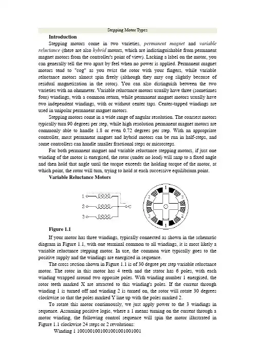
Stepping Motor TypesIntroductionStepping motors come in two varieties, permanent magnet and variable reluctance (there are also hybrid motors, which are indistinguishable from permanent magnet motors from the controller's point of view). Lacking a label on the motor, you can generally tell the two apart by feel when no power is applied. Permanent magnet motors tend to "cog" as you twist the rotor with your fingers, while variable reluctance motors almost spin freely (although they may cog slightly because of residual magnetization in the rotor). You can also distinguish between the two varieties with an ohmmeter. Variable reluctance motors usually have three (sometimes four) windings, with a common return, while permanent magnet motors usually have two independent windings, with or without center taps. Center-tapped windings are used in unipolar permanent magnet motors.Stepping motors come in a wide range of angular resolution. The coarsest motors typically turn 90 degrees per step, while high resolution permanent magnet motors are commonly able to handle 1.8 or even 0.72 degrees per step. With an appropriate controller, most permanent magnet and hybrid motors can be run in half-steps, and some controllers can handle smaller fractional steps or microsteps.For both permanent magnet and variable reluctance stepping motors, if just one winding of the motor is energised, the rotor (under no load) will snap to a fixed angle and then hold that angle until the torque exceeds the holding torque of the motor, at which point, the rotor will turn, trying to hold at each successive equilibrium point.Variable Reluctance MotorsFigure 1.1If your motor has three windings, typically connected as shown in the schematic diagram in Figure 1.1, with one terminal common to all windings, it is most likely a variable reluctance stepping motor. In use, the common wire typically goes to the positive supply and the windings are energized in sequence.The cross section shown in Figure 1.1 is of 30 degree per step variable reluctance motor. The rotor in this motor has 4 teeth and the stator has 6 poles, with each winding wrapped around two opposite poles. With winding number 1 energised, the rotor teeth marked X are attracted to this winding's poles. If the current through winding 1 is turned off and winding 2 is turned on, the rotor will rotate 30 degrees clockwise so that the poles marked Y line up with the poles marked 2.To rotate this motor continuously, we just apply power to the 3 windings in sequence. Assuming positive logic, where a 1 means turning on the current through a motor winding, the following control sequence will spin the motor illustrated in Figure 1.1 clockwise 24 steps or 2 revolutions:Winding 1 1001001001001001001001001Winding 2 0100100100100100100100100Winding 3 0010010010010010010010010 time --->The section of this tutorial on Mid-Level Control provides details on methods for generating such sequences of control signals, while the section on Control Circuits discusses the power switching circuitry needed to drive the motor windings from such control sequences.There are also variable reluctance stepping motors with 4 and 5 windings, requiring 5 or 6 wires. The principle for driving these motors is the same as that for the three winding variety, but it becomes important to work out the correct order to energise the windings to make the motor step nicely.The motor geometry illustrated in Figure 1.1, giving 30 degrees per step, uses the fewest number of rotor teeth and stator poles that performs satisfactorily. Using more motor poles and more rotor teeth allows construction of motors with smaller step angle. Toothed faces on each pole and a correspondingly finely toothed rotor allows for step angles as small as a few degrees.Unipolar MotorsFigure 1.2Unipolar stepping motors, both Permanent magnet and hybrid stepping motors with 5 or 6 wires are usually wired as shown in the schematic in Figure 1.2, with a center tap on each of two windings. In use, the center taps of the windings are typically wired to the positive supply, and the two ends of each winding are alternately grounded to reverse the direction of the field provided by that winding.The motor cross section shown in Figure 1.2 is of a 30 degree per step permanent magnet or hybrid motor -- the difference between these two motor types is not relevant at this level of abstraction. Motor winding number 1 is distributed between the top and bottom stator pole, while motor winding number 2 is distributed between the left and right motor poles. The rotor is a permanent magnet with 6 poles, 3 south and 3 north, arranged around its circumfrence.For higher angular resolutions, the rotor must have proportionally more poles. The 30 degree per step motor in the figure is one of the most common permanent magnet motor designs, although 15 and 7.5 degree per step motors are widely available. Permanent magnet motors with resolutions as good as 1.8 degrees per step are made, and hybrid motors are routinely built with 3.6 and 1.8 degrees per step, with resolutions as fine as 0.72 degrees per step available.As shown in the figure, the current flowing from the center tap of winding 1 to terminal a causes the top stator pole to be a north pole while the bottom stator pole is a south pole. This attracts the rotor into the position shown. If the power to winding 1 is removed and winding 2 is energised, the rotor will turn 30 degrees, or one step.To rotate the motor continuously, we just apply power to the two windings in sequence. Assuming positive logic, where a 1 means turning on the current through a motor winding, the following two control sequences will spin the motor illustrated in Figure 1.2 clockwise 24 steps or 2 revolutions:Winding 1a 1000100010001000100010001Winding 1b 0010001000100010001000100Winding 2a 0100010001000100010001000Winding 2b 0001000100010001000100010 time --->Winding 1a 1100110011001100110011001Winding 1b 0011001100110011001100110Winding 2a 0110011001100110011001100Winding 2b 1001100110011001100110011 time --->Note that the two halves of each winding are never energized at the same time. Both sequences shown above will rotate a permanent magnet one step at a time. The top sequence only powers one winding at a time, as illustrated in the figure above; thus, it uses less power. The bottom sequence involves powering two windings at a time and generally produces a torque about 1.4 times greater than the top sequence while using twice as much power.The section of this tutorial on Mid-Level Control provides details on methods for generating such sequences of control signals, while the section on Control Circuits discusses the power switching circuitry needed to drive the motor windings from such control sequences.The step positions produced by the two sequences above are not the same; as a result, combining the two sequences allows half stepping, with the motor stopping alternately at the positions indicated by one or the other sequence. The combined sequence is as follows:Winding 1a 11000001110000011100000111Winding 1b 00011100000111000001110000Winding 2a 01110000011100000111000001Winding 2b 00000111000001110000011100time --->Bipolar MotorsFigure 1.3Bipolar permanent magnet and hybrid motors are constructed with exactly the same mechanism as is used on unipolar motors, but the two windings are wired more simply, with no center taps. Thus, the motor itself is simpler but the drive circuitry needed to reverse the polarity of each pair of motor poles is more complex. The schematic in Figure 1.3 shows how such a motor is wired, while the motor cross section shown here is exactly the same as the cross section shown in Figure 1.2.The drive circuitry for such a motor requires an H-bridge control circuit for each winding; these are discussed in more detail in the section on Control Circuits. Briefly, an H-bridge allows the polarity of the power applied to each end of each winding to be controlled independently. The control sequences for single stepping such a motor are shown below, using + and - symbols to indicate the polarity of the power applied to each motor terminal:Terminal 1a +---+---+---+--- ++--++--++--++--Terminal 1b --+---+---+---+- --++--++--++--++Terminal 2a -+---+---+---+-- -++--++--++--++-Terminal 2b ---+---+---+---+ +--++--++--++--+ time --->Note that these sequences are identical to those for a unipolar permanent magnet motor, at an abstract level, and that above the level of the H-bridge power switching electronics, the control systems for the two types of motor can be identical.Note that many full H-bridge driver chips have one control input to enable the output and another to control the direction. Given two such bridge chips, one per winding, the following control sequences will spin the motor identically to the control sequences given above:Enable 1 1010101010101010 1111111111111111Direction 1 1x0x1x0x1x0x1x0x 1100110011001100Enable 2 0101010101010101 1111111111111111Direction 2 x1x0x1x0x1x0x1x0 0110011001100110 time --->To distinguish a bipolar permanent magnet motor from other 4 wire motors, measure the resistances between the different terminals. It is worth noting that some permanent magnet stepping motors have 4 independent windings, organized as two sets of two. Within each set, if the two windings are wired in series, the result can be used as a high voltage bipolar motor. If they are wired in parallel, the result can be used as a low voltage bipolar motor. If they are wired in series with a center tap, the result can be used as a low voltage unipolar motor. Bifilar MotorsBifilar windings on a stepping motor are applied to the same rotor and stator geometry as a bipolar motor, but instead of winding each coil in the stator with a single wire, two wires are wound in parallel with each other. As a result, the motor has 8 wires, not four.In practice, motors with bifilar windings are always powered as either unipolar or bipolar motors. Figure 1.4 shows the alternative connections to the windings of such a motor.Figure 1.4To use a bifilar motor as a unipolar motor, the two wires of each winding are connected in series and the point of connection is used as a center-tap. Winding 1 in Figure 1.4 is shown connected this way.To use a bifilar motor as a bipolar motor, the two wires of each winding are connected either in parallel or in series. Winding 2 in Figure 1.4 is shown with a parallel connection; this allows low voltage high-current operation. Winding 1 in Figure 1.4 is shown with a series connection; if the center tap is ignored, this allows operation at a higher voltage and lower current than would be used with the windings in parallel.It should be noted that essentially all 6-wire motors sold for bipolar use are actually wound using bifilar windings, so that the external connection that serves as a center tap is actually connected as shown for winding 1 in Figure 1.4. Naturally, therefore, any unipolar motor may be used as a bipolar motor at twice the rated voltage and half the rated current as is given on the nameplate.The question of the correct operating voltage for a bipolar motor run as a unipolar motor, or for a bifilar motor with the motor windings in series is not as trivial as it might first appear. There are three issues: The current carrying capacity of the wire, cooling the motor, and avoiding driving the motor's magnetic circuits into saturation. Thermal considerations suggest that, if the windings are wired in series, the voltage should only be raised by the square root of 2. The magnetic field in the motor depends on the number of ampere turns; when the two half-windings are run in series, the number of turns is doubled, but because a well-designed motor has magnetic circuits that are close to saturation when the motor is run at its rated voltage and current, increasing the number of ampere-turns does not make the field any stronger. Therefore, when a motor is run with the two half-windings in series, the current should be halved in order to avoid saturation; or, in other words, the voltage across the motor winding should be the same as it was.For those who salvage old motors, finding an 8-wire motor poses a challenge! Which of the 8 wires is which? It is not hard to figure this out using an ohm meter, an AC volt meter, and a low voltage AC source. First, use the ohm meter to identify the motor leads that are connected to each other through the motor windings. Then, connect a low-voltage AC source to one of these windings. The AC voltage should be below the advertised operating voltage of the motor; voltages under 1 volt are recommended. The geometry of the magnetic circuits of the motor guarantees that the two wires of a bifilar winding will be strongly coupled for AC signals, while there should be almost no coupling to the other two wires. Therefore, probing with an AC volt meter should disclose which of the other three windings is paired to the winding under power. Multiphase MotorsFigure 1.5A less common class of permanent magnet or hybrid stepping motor is wired with all windings of the motor in a cyclic series, with one tap between each pair ofwindings in the cycle, or with only one end of each motor winding exposed while the other ends of each winding are tied together to an inaccessible internal connection. In the context of 3-phase motors, these configurations would be described as Delta and Y configurations, but they are also used with 5-phase motors, as illustrated in Figure 1.5. Some multiphase motors expose all ends of all motor windings, leaving it to the user to decide between the Delta and Y configurations, or alternatively, allowing each winding to be driven independently.Control of either one of these multiphase motors in either the Delta or Y configuration requires 1/2 of an H-bridge for each motor terminal. It is noteworthy that 5-phase motors have the potential of delivering more torque from a given package size because all or all but one of the motor windings are energised at every point in the drive cycle. Some 5-phase motors have high resolutions on the order of 0.72 degrees per step (500 steps per revolution).Many automotive alternators are built using a 3-phase hybrid geometry with either a permanent magnet rotor or an electromagnet rotor powered through a pair of slip-rings. These have been successfully used as stepping motors in some heavy duty industrial applications; step angles of 10 degrees per step have been reported.With a 5-phase motor, there are 10 steps per repeat in the stepping cycle, as shown below:Terminal 1 +++-----+++++-----++Terminal 2 --+++++-----+++++---Terminal 3 +-----+++++-----++++Terminal 4 +++++-----+++++-----Terminal 5 ----+++++-----+++++-time --->With a 3-phase motor, there are 6 steps per repeat in the stepping cycle, as shown below:Terminal 1 +++---+++---Terminal 2 --+++---+++-Terminal 3 +---+++---++time --->Here, as in the bipolar case, each terminal is shown as being either connected to the positive or negative bus of the motor power system. Note that, at each step, only one terminal changes polarity. This change removes the power from one winding attached to that terminal (because both terminals of the winding in question are of the same polarity) and applies power to one winding that was previously idle. Given the motor geometry suggested by Figure 1.5, this control sequence will drive the motor through two revolutions.To distinguish a 5-phase motor from other motors with 5 leads, note that, if the resistance between two consecutive terminals of the 5-phase motor is R, the resistance between non-consecutive terminals will be 1.5R.Note that some 5-phase motors have 5 separate motor windings, with a total of 10 leads. These can be connected in the star configuration shown above, using 5 half-bridge driver circuits, or each winding can be driven by its own full-bridge. While the theoretical component count of half-bridge drivers is lower, the availability of integrated full-bridge chips may make the latter approach preferable.步进电机•介绍•变磁阻电机•单极电机•双极电机•单一电机•多相电机介绍步进电动机分成两类、永磁和变磁阻(也有混合电机、永磁电机与从控制器的观点)。
About stepper motor and drive systemStep characteristics for machine for angular displacement for entering the electrical engineering is first kind will give or get an electric shocking the pulse signal conversion cowgirl or line potential moving battery carry outing a piece, having the fast stopping, accurate step entering and directly accepting the arithmetic figure measuring, because of but got the extensive application.Such as in the drafting machine, print the machine and optical instrument inside, and all adopt the inside of a place control system for entering the electrical engineering to positioning to paint the pen print head or optical prinipal, especially indrstry process the type control, and move to spread to feel the to can immediately attain the precision fixed position because of its precision and need not potential, and control the technique along with the calculator of continuously deveolp, applied to would be more and more extensive.Control and can is divided into the simple control sum the complicacy to control to motor two kind.The simple control points to proceeds to start to motor, the system move, positive and negative revolution and sequential plicacy the control point to the motor's revolving speed, screw angle, turning moment, tension, electric current etc. physics quantisty progress control.Control technique that the development that motor get force is in latest development achievement that micro-electronics technique, electric power electronics, spread to feel the the technique, automatic control the technique, tiny machine the application technique to wait.Exactly the advance of these techniques make the motor control the technique at near two 10-year insides change for turn overing the ground of day is take placed.Among them the motor's control division have already been controled by emulation gradually let locate to regard single flake machine as principle of microprocessor control, formation the mix control system of the arithmetic figure and emulation and the application of the pure arithmetic figure control system, combine control the direction to total amount word to quickly deveolp.The motor's drive part of power forusing the piece experienced a few renewals to change the on behalf, current switch speed sooner, more simple whole type power piece of control the MOSFET become the main current with IGBT.Stepper motors have the following benefits:•Low cost•Ruggedness•Simplicity in construction•High reliability•No maintenance•Wide acceptance•No tweaking to stabilize•No feedback components are needed•They work in just about any environment•Inherently more failsafe than servo motors.There is virtually no conceivable failure within the stepper drive module that could cause the motor to run away. Stepper motors are simple to drive and control in an open-loop configuration. They only require four leads. They provide excellent torque at low speeds, up to 5 times the continuous torque of a brush motor of the same frame size or double the torque of the equivalent brushless motor. This often eliminates the need for a gearbox. A stepper-driven-system is inherently stiff, with known limits to the dynamic position error.Stepper Motor DisadvantagesStepper motors have the following disadvantages:•Resonance effects and relatively long settlingtimes•Rough performance at low speed unless amicrostep drive is used•Liability to undetected position loss as a result ofoperating open-loop•They consume current regardless of loadconditions and therefore tend to run hot•Losses at speed are relatively high and can causeexcessive heating, and they are frequently noisy(especially at high speeds).•They can exhibit lag-lead oscillation, which isdifficult to damp. There is a limit to their availablesize, and positioning accuracy relies on themechanics (e.g., ballscrew accuracy). Many ofthese drawbacks can be overcome by the use ofa closed-loop control scheme.Note: The Compumotor Zeta Series minimizes orreduces many of these different stepper motor disadvantages.There are three main stepper motor types:•Permanent Magnet (P.M.) Motors•Variable Reluctance (V.R.) Motors•Hybrid MotorsWhen the motor is driven in its full-step mode, energizing two windings or “phases”at a time (see Fig. 1.8), the torque available on each step will be the same (subject to very small variations in the motor and drive characteristics). In the half-step mode, we are alternately energizing two phases and then only one as shown in Fig. 1.9. Assuming the drive delivers the same winding current in each case, this will cause greater torque to be produced when there are two windings energized. In other words, alternate steps will be strong and weak. This does not represent a major deterrent to motor performance—the available torque is obviously limited by the weaker step, but there will be a significant improvement in low-speed smoothness over the full-step mode.Applications in hazardous environmentsor in a vacuum may not be able to use a brushed motor. Either a stepper or a brushless motor is called for, depending on the demands of the load. Bear in mind that heat dissipation may be a problem in a vacuum when the loads are excessive.continuous duty applications suit the servo motor, and in fact a step motor should be avoided in such applications because the high-speed losses can cause excessive motor heating.are the natural domain of the stepper due to its high torque at low speeds, good torque-to-inertia ratio and lack of commutation problems.The brushes of the DC motor can limit its potential for frequent starts, stops and direction changes.continuous duty applications are appropriate to the step motor. At low speeds it is very efficient in terms of torque output relative to both size and input power. Microstepping can be used to improve smoothness in lowspeed applications such as a metering pump drive for very accurate flow control.Stepper motor is a stepper motor for precise electrical and mechanical actuators, which are widely used in industrial machinery, digital control, for the system reliability, interoperability, maintainability, and cost-optimal, according to the control system functional requirements and Control system through the microcontroller memory, I/O interface, interrupt, keyboard, LED display of the expansion of the annular distributor stepping motor, drive and protection circuit, man-machine interface circuit, interrupt system and reset circuit, a single voltage drive circuit, etc.designed to achieve a four-phase stepper motor rotating, and emergency stop functions.To achieve the stepping motor system in NC Machine Tools, system design, two external interrupts, in order to achieve within a certain period of time stepper motor repeated Reversible function, ie, the turret CNC automatic feed movement. With the continuous development of single chip microcomputer, microcontroller in household electronic products widely applied, since the since the early sixties, the stepper motor applications are greatly enhanced.People use it to drive the clock and other instruments with pointers, printers, plotters, disk CD-ROM drive, a variety of automatic control valves, various tools, as well as robots and other mechanical devices.In addition,as the acIn addition, as the actuator, stepper motor is one of mechanical and electrical integration of the key products are widely used in a variety of automatic control systems, microelectronics and computer technology with the development of its requirements with the Japanese fear of growing in all the field of application of the national economy has. Stepper motor digital control system of electromechanical actuators commonly used, due to its high precision, small size, flexible to control, so the smart meter and position control hasbeen widely used in large-scale integrated circuits technology development, and SCM The increasing popularity of design features, the lowest price of the stepper motor control driver provides advanced technology and adequate resources.步进电机及其驱动系统简介步进电机是一种将电脉冲信号转换成相应的角位移或线位移的机电执行元件,具有快速启停、精确步进以及直接接受数字量的特点,因而得到了广泛的应用。
步进电机细分数英文单词全文共四篇示例,供读者参考第一篇示例:Stepper motors play a crucial role in a wide range of devices and machinery today, from 3D printers and CNC machines to robotics and medical equipment. One important parameter that defines the performance of a stepper motor is the number of steps it can take per revolution, known as the step resolution or step division. In this article, we will delve into the concept of step division in stepper motors and explore how it impacts their operation and performance.第二篇示例:Stepper motor is a kind of electric motor that moves in discrete steps. It is different from other types of motors in that it divides a full rotation into a number of equal steps. One of the key parameters that define the performance of a stepper motor is the number of steps per revolution, also known as the step resolution or step size.第三篇示例:Stepper Motor Step CountA stepper motor is a type of motor that moves in discrete steps rather than continuously rotating like a traditional motor. This unique characteristic makes stepper motors ideal for precision control applications where accuracy and repeatability are essential. In order to achieve precise control of a stepper motor, the concept of step count or step resolution comes into play.第四篇示例:Stepper motors, also known as step motors, are a type of brushless DC electric motor that converts electrical pulses into mechanical movement. They are widely used in various applications that require precise positioning and speed control, such as 3D printers, CNC machines, and robotic arms.。
毕业设计(论文)外文文献翻译文献、资料中文题目:步进电机的知识文献、资料英文题目:Knowledge of the stepper motor文献、资料来源:文献、资料发表(出版)日期:院(部):专业:班级:姓名:学号:指导教师:翻译日期: 2017.02.14外文文献:Knowledge of the stepper motorWhat is a stepper motor:Stepper motor is a kind of electrical pulses into angular displacement of the implementing agency. Popular little lesson: When the driver receives a step pulse signal, it will drive a stepper motor to set the direction of rotation at a fixed angle (and the step angle). You can control the number of pulses to control the angular displacement, so as to achieve accurate positioning purposes; the same time you can control the pulse frequency to control the motor rotation speed and acceleration, to achieve speed control purposes.What kinds of stepper motor sub-:In three stepper motors: permanent magnet (PM), reactive (VR) and hybrid (HB) permanent magnet stepper usually two-phase, torque, and smaller, step angle of 7.5 degrees or the general 15 degrees; reaction step is generally three-phase, can achieve high torque output, step angle of 1.5 degrees is generally, but the noise and vibration are large. 80 countries in Europe and America have been eliminated; hybrid stepper is a mix of permanent magnet and reactive advantages. It consists of two phases and the five-phase: two-phase step angle of 1.8 degrees while the general five-phase step angle of 0.72 degrees generally. The most widely used Stepper Motor.What is to keep the torque (HOLDING TORQUE)How much precision stepper motor? Whether the cumulative:The general accuracy of the stepper motor step angle of 3-5%, and not cumulative.Stepper motor to allow the minimum amount of surface temperatureStepper motor to allow the minimum amount of surface temperature:Stepper motor causes the motor temperature is too high the first magnetic demagnetization, resulting in loss of torque down even further, so the motor surface temperature should be the maximum allowed depending on the motor demagnetization of magnetic material points; Generally speaking, the magnetic demagnetization points are above 130 degrees Celsius, and some even as high as 200 degrees Celsius, so the stepper motor surface temperature of 80-90 degrees Celsius is normal.How to determine the stepper motor driver DC power supply:A. Determination of the voltageHybrid stepping motor driver power supply voltage is generally a wide range (such as the IM483 supply voltage of 12 ~ 48VDC), the supply voltage is usually based on the work of the motor speed and response to the request to choose. If the motor operating speed higher or faster response to the request, then the voltage value is high, but note that the ripple voltage can not exceed the maximum input voltage of the drive, or it may damage the drive.B. Determination of CurrentPower supply current is generally based on the output phase current drive I to determine. If a linear power supply, power supply current is generally preferable 1.1 to 1.3 times the I; if we adopt the switching power supply, power supply current is generally preferable to I, 1.5 to 2.0 times.The main characteristics of stepping motor:A stepper motor drive can be added operate pulse drive signal must be no pulse when the stepper motor at rest, such asIf adding the appropriate pulse signal, it will to a certain angle (called the step angle) rotation. Rotation speed and pulse frequency is proportional to.2 Dragon step angle stepper motor version is 7.5 degrees, 360 degrees around, takes 48 pulses to complete.3 stepper motor has instant start and rapid cessation of superior characteristics.Change the pulse of the order of 4, you can easily change the direction of rotation. Therefore, the current printers, plotters, robotics, and so devices are the core of the stepper motor as the driving force.Stepper motor control exampleWe use four-phase unipolar stepper motor as an example. The structure shown in Figure 1: Four four-phase winding leads (as opposed to phase A1 A2 B1 phase phase B2) and two public lines (to the power of positive). The windings of one phase to the power of the ground. So that the windings will be inspired. We use four-phase eight-beat control, ie, 1 phase 2 phase alternating turn, would enhance resolution. 0.9 ° per step can be transferred to control the motor excitation is transferred in order as follows:If the requirements of motor reversal, the transmission excitation signal can be reversed. 2 control schemeControl system block diagram is as followsThe program uses AT89S51 as the main control device. It is compatible with the AT89C51, but also increased the SPI interface and the watchdog module, which not only makes the debugging process becomes easy and also more stable. The microcontroller in the program mainly for field signal acquisition and operation of the stepper motor to calculate the direction and speed information. Then sent to the CPLD.CPLD with EPM7128SLC84-15, EPM7128 programmable logic device of large-scale, for the ALTERA company's MAX7000 family. High impedance, electrically erasable and other characteristics, can be used for the 2500 unit, the working voltage of +5 V. CPLD receives information sent from the microcontroller after converted to the corresponding control signal output to the stepper motor drive. Put the control signal drives the motor windings after the input, to achieve effective control of the motor. 2.1 The hardware structure of the motor drive Motor drive using the following circuit:R1-R8 in which the resistance value of 320Ω. R9-R12 resistance value 2.2KΩ. Q1-Q4 as Darlington D401A, Q5-Q8 for the S8550. J1, J2 and the stepper motor connected to the six-lead。
英文文献1原文Stepping Motor Types•Introduction•Variable Reluctance Motors•Unipolar Motors•Bipolar Motors•Bifilar Motors•Multiphase MotorsIntroductionStepping motors come in two varieties, permanent magnet and variable reluctance (there are also hybrid motors, which are indistinguishable from permanent magnet motors from the controller's point of view). Lacking a label on the motor, you can generally tell the two apart by feel when no power is applied. Permanent magnet motors tend to "cog" as you twist the rotor with your fingers, while variable reluctance motors almost spin freely (although they may cog slightly because of residual magnetization in the rotor). You can also distinguish between the two varieties with an ohmmeter. Variable reluctance motors usually have three (sometimes four) windings, with a common return, while permanent magnet motors usually have two independent windings, with or without center taps. Center-tapped windings are used in unipolar permanent magnet motors.Stepping motors come in a wide range of angular resolution. The coarsest motors typically turn 90 degrees per step, while high resolution permanent magnet motors are commonly able to handle 1.8 or even 0.72 degrees per step. With an appropriate controller, most permanent magnet and hybrid motors can be run in half-steps, and some controllers can handle smaller fractional steps or microsteps.For both permanent magnet and variable reluctance stepping motors, if just one winding of the motor is energised, the rotor (under no load) will snap to a fixed angle and then hold that angle until the torque exceeds the holding torque of the motor, at which point, the rotor will turn, trying to hold at each successive equilibrium point.Variable Reluctance MotorsFigure 1.1If your motor has three windings, typically connected as shown in the schematic diagram in Figure 1.1, with one terminal common to all windings, it is most likely a variable reluctance stepping motor. In use, the common wire typically goes to the positive supply and the windings are energized in sequence.The cross section shown in Figure 1.1 is of 30 degree per step variable reluctance motor. The rotor in this motor has 4 teeth and the stator has 6 poles, with each winding wrapped around two opposite poles. With winding number 1 energised, the rotor teeth marked X are attracted to this winding's poles. If the current through winding 1 is turned off and winding 2 is turned on, the rotor will rotate 30 degrees clockwise so that the poles marked Y line up with the poles marked 2.To rotate this motor continuously, we just apply power to the 3 windings in sequence. Assuming positive logic, where a 1 means turning on the current through a motor winding, the following control sequence will spin the motor illustrated in Figure 1.1 clockwise 24 steps or 2 revolutions:Winding 1 1001001001001001001001001Winding 2 0100100100100100100100100Winding 3 0010010010010010010010010time --->The section of this tutorial on Mid-Level Control provides details on methods for generating such sequences of control signals, while the section on Control Circuits discusses the power switching circuitry needed to drive the motor windings from such control sequences.There are also variable reluctance stepping motors with 4 and 5 windings, requiring 5 or 6 wires. The principle for driving these motors is the same as that for the three winding variety, but it becomes important to work out the correct order to energise the windings to make the motor step nicely.The motor geometry illustrated in Figure 1.1, giving 30 degrees per step, uses the fewest number of rotor teeth and stator poles that performs satisfactorily. Using more motor poles and more rotor teeth allows construction of motors with smaller step angle. Toothed faces on each pole and a correspondingly finely toothed rotor allows for step angles as small as a few degrees.Unipolar MotorsFigure 1.2Unipolar stepping motors, both Permanent magnet and hybrid stepping motors with 5 or 6 wires are usually wired as shown in the schematic in Figure 1.2, with a center tap on each of two windings. In use, the center taps of the windings are typically wired to the positive supply, and the two ends of each winding are alternately grounded to reverse the direction of the field provided by that winding.The motor cross section shown in Figure 1.2 is of a 30 degree per step permanent magnet or hybrid motor -- the difference between these two motor types is not relevant at this level of abstraction. Motor winding number 1 is distributed between the top and bottom stator pole, while motor winding number 2 is distributed between the left and right motor poles. The rotor is a permanent magnet with 6 poles, 3 south and 3 north, arranged around its circumfrence.For higher angular resolutions, the rotor must have proportionally more poles. The 30 degree per step motor in the figure is one of the most common permanent magnet motor designs, although 15 and 7.5 degree per step motors are widely available. Permanent magnet motors with resolutions as good as 1.8 degrees per step are made, and hybrid motors are routinely built with 3.6 and 1.8 degrees per step, with resolutions as fine as 0.72 degrees per step available.As shown in the figure, the current flowing from the center tap of winding 1 to terminal a causes the top stator pole to be a north pole while the bottom stator pole isa south pole. This attracts the rotor into the position shown. If the power to winding 1 is removed and winding 2 is energised, the rotor will turn 30 degrees, or one step.To rotate the motor continuously, we just apply power to the two windings in sequence. Assuming positive logic, where a 1 means turning on the current through a motor winding, the following two control sequences will spin the motor illustrated in Figure 1.2 clockwise 24 steps or 2 revolutions:Winding 1a 1000100010001000100010001Winding 1b 0010001000100010001000100Winding 2a 0100010001000100010001000Winding 2b 0001000100010001000100010time --->Winding 1a 1100110011001100110011001Winding 1b 0011001100110011001100110Winding 2a 0110011001100110011001100Winding 2b 1001100110011001100110011time --->Note that the two halves of each winding are never energized at the same time. Both sequences shown above will rotate a permanent magnet one step at a time. The top sequence only powers one winding at a time, as illustrated in the figure above; thus, it uses less power. The bottom sequence involves powering two windings at a time and generally produces a torque about 1.4 times greater than the top sequence while using twice as much power.The section of this tutorial on Mid-Level Control provides details on methods for generating such sequences of control signals, while the section on Control Circuits discusses the power switching circuitry needed to drive the motor windings from such control sequences.The step positions produced by the two sequences above are not the same; as a result, combining the two sequences allows half stepping, with the motor stopping alternately at the positions indicated by one or the other sequence. The combined sequence is as follows:Winding 1a 11000001110000011100000111Winding 1b 00011100000111000001110000Winding 2a 01110000011100000111000001Winding 2b 00000111000001110000011100time --->Bipolar MotorsFigure 1.3Bipolar permanent magnet and hybrid motors are constructed with exactly the same mechanism as is used on unipolar motors, but the two windings are wired more simply, with no center taps. Thus, the motor itself is simpler but the drive circuitry needed to reverse the polarity of each pair of motor poles is more complex. The schematic in Figure 1.3 shows how such a motor is wired, while the motor cross section shown here is exactly the same as the cross section shown in Figure 1.2.The drive circuitry for such a motor requires an H-bridge control circuit for each winding; these are discussed in more detail in the section on Control Circuits. Briefly, an H-bridge allows the polarity of the power applied to each end of each winding to be controlled independently. The control sequences for single stepping such a motor are shown below, using + and - symbols to indicate the polarity of the power applied to each motor terminal:Terminal 1a +---+---+---+--- ++--++--++--++--Terminal 1b --+---+---+---+- --++--++--++--++Terminal 2a -+---+---+---+-- -++--++--++--++-Terminal 2b ---+---+---+---+ +--++--++--++--+time --->Note that these sequences are identical to those for a unipolar permanent magnet motor, at an abstract level, and that above the level of the H-bridge power switching electronics, the control systems for the two types of motor can be identical.Note that many full H-bridge driver chips have one control input to enable the output and another to control the direction. Given two such bridge chips, one perwinding, the following control sequences will spin the motor identically to the control sequences given above:Enable 1 1010101010101010 1111111111111111Direction 1 1x0x1x0x1x0x1x0x 1100110011001100Enable 2 0101010101010101 1111111111111111Direction 2 x1x0x1x0x1x0x1x0 0110011001100110time --->To distinguish a bipolar permanent magnet motor from other 4 wire motors, measure the resistances between the different terminals. It is worth noting that some permanent magnet stepping motors have 4 independent windings, organized as two sets of two. Within each set, if the two windings are wired in series, the result can be used as a high voltage bipolar motor. If they are wired in parallel, the result can be used as a low voltage bipolar motor. If they are wired in series with a center tap, the result can be used as a low voltage unipolar motor.Bifilar MotorsBifilar windings on a stepping motor are applied to the same rotor and stator geometry as a bipolar motor, but instead of winding each coil in the stator with a single wire, two wires are wound in parallel with each other. As a result, the motor has 8 wires, not four.In practice, motors with bifilar windings are always powered as either unipolar or bipolar motors. Figure 1.4 shows the alternative connections to the windings of such a motor.Figure 1.4To use a bifilar motor as a unipolar motor, the two wires of each winding are connected in series and the point of connection is used as a center-tap. Winding 1 in Figure 1.4 is shown connected this way.To use a bifilar motor as a bipolar motor, the two wires of each winding are connected either in parallel or in series. Winding 2 in Figure 1.4 is shown with a parallel connection; this allows low voltage high-current operation. Winding 1 in Figure 1.4 is shown with a series connection; if the center tap is ignored, this allows operation at a higher voltage and lower current than would be used with the windings in parallel.It should be noted that essentially all 6-wire motors sold for bipolar use are actually wound using bifilar windings, so that the external connection that serves as a center tap is actually connected as shown for winding 1 in Figure 1.4. Naturally, therefore, any unipolar motor may be used as a bipolar motor at twice the rated voltage and half the rated current as is given on the nameplate.The question of the correct operating voltage for a bipolar motor run as a unipolar motor, or for a bifilar motor with the motor windings in series is not as trivial as it might first appear. There are three issues: The current carrying capacity of the wire, cooling the motor, and avoiding driving the motor's magnetic circuits into saturation. Thermal considerations suggest that, if the windings are wired in series, the voltage should only be raised by the square root of 2. The magnetic field in the motor depends on the number of ampere turns; when the two half-windings are run in series, the number of turns is doubled, but because a well-designed motor has magnetic circuits that are close to saturation when the motor is run at its rated voltage and current, increasing the number of ampere-turns does not make the field any stronger. Therefore, when a motor is run with the two half-windings in series, the current should be halved in order to avoid saturation; or, in other words, the voltage across the motor winding should be the same as it was.For those who salvage old motors, finding an 8-wire motor poses a challenge! Which of the 8 wires is which? It is not hard to figure this out using an ohm meter, an AC volt meter, and a low voltage AC source. First, use the ohm meter to identify the motor leads that are connected to each other through the motor windings. Then, connect a low-voltage AC source to one of these windings. The AC voltage should be below the advertised operating voltage of the motor; voltages under 1 volt are recommended. The geometry of the magnetic circuits of the motor guarantees that the two wires of a bifilar winding will be strongly coupled for AC signals, while there should be almost no coupling to the other two wires. Therefore, probing with an ACvolt meter should disclose which of the other three windings is paired to the winding under power.Multiphase MotorsFigure 1.5A less common class of permanent magnet or hybrid stepping motor is wired with all windings of the motor in a cyclic series, with one tap between each pair of windings in the cycle, or with only one end of each motor winding exposed while the other ends of each winding are tied together to an inaccessible internal connection. In the context of 3-phase motors, these configurations would be described as Delta and Y configurations, but they are also used with 5-phase motors, as illustrated in Figure 1.5. Some multiphase motors expose all ends of all motor windings, leaving it to the user to decide between the Delta and Y configurations, or alternatively, allowing each winding to be driven independently.Control of either one of these multiphase motors in either the Delta or Y configuration requires 1/2 of an H-bridge for each motor terminal. It is noteworthy that 5-phase motors have the potential of delivering more torque from a given package size because all or all but one of the motor windings are energised at every point in the drive cycle. Some 5-phase motors have high resolutions on the order of 0.72 degrees per step (500 steps per revolution).Many automotive alternators are built using a 3-phase hybrid geometry with either a permanent magnet rotor or an electromagnet rotor powered through a pair of slip-rings. These have been successfully used as stepping motors in some heavy duty industrial applications; step angles of 10 degrees per step have been reported.With a 5-phase motor, there are 10 steps per repeat in the stepping cycle, as shown below:Terminal 1 +++-----+++++-----++Terminal 2 --+++++-----+++++---Terminal 3 +-----+++++-----++++Terminal 4 +++++-----+++++-----Terminal 5 ----+++++-----+++++-time --->With a 3-phase motor, there are 6 steps per repeat in the stepping cycle, as shown below:Terminal 1 +++---+++---Terminal 2 --+++---+++-Terminal 3 +---+++---++time --->Here, as in the bipolar case, each terminal is shown as being either connected to the positive or negative bus of the motor power system. Note that, at each step, only one terminal changes polarity. This change removes the power from one winding attached to that terminal (because both terminals of the winding in question are of the same polarity) and applies power to one winding that was previously idle. Given the motor geometry suggested by Figure 1.5, this control sequence will drive the motor through two revolutions.To distinguish a 5-phase motor from other motors with 5 leads, note that, if the resistance between two consecutive terminals of the 5-phase motor is R, the resistance between non-consecutive terminals will be 1.5R.Note that some 5-phase motors have 5 separate motor windings, with a total of 10 leads. These can be connected in the star configuration shown above, using 5 half-bridge driver circuits, or each winding can be driven by its own full-bridge. While the theoretical component count of half-bridge drivers is lower, the availability of integrated full-bridge chips may make the latter approach preferable.。
步进电机_原理、分类和特点_中英文翻译EnglishStepper motorStepper motor is the electric pulse signals into angulardisplacement or linear displacement of the open-loop stepper motorcontrol element pieces. In the case of non-overloaded, the motor speed, stop position depends only on the pulse frequency and pulse number, regardless of load changes, when the driver receives a step pulse signal, it will drive a stepper motor to Set the direction of rotation of afixed angle, called the "step angle", which the angle of rotation isfixed step by step operation. Number of pulses can be controlled by controlling the angular displacement, so as to achieve accurate positioning purposes; the same time by controlling the pulse frequencyto control the motor rotation speed and acceleration, to achieve speed control purposes.WorkInduction motor is a stepper motor, does it work is the use of electronic circuits, the DC power supply into a time-sharing, multi-phase timing control current, this current stepper motor power supply, the stepper motor to work properly , The drive is sharing power supplyfor the stepper motor, the polyphase timing controllerAlthough the stepper motor has been widely used, but the steppermotor does not like a normal DC motor, AC motor in the conventional use.It must be double-ring pulse signal, power driver circuit composed of the control system can be used. Therefore, it is not easy with a good stepping motor, which involves mechanical, electrical, electronics and computers, and many other specialized knowledge.As the stepper motor actuators, electromechanical integration, oneof the key products, widely used in a variety of automatic control systems. With the development of microelectronics and computer technology, increasing demand for stepper motor, has applications in all areas of the national economy.CategoriesNow more commonly used include the reaction of step motor stepper motor (VR), permanent magnet stepper motor (PM), hybrid stepper motors (HB) and single-phase stepper motor.Permanent magnet stepper motorPermanent magnet stepper motor is generally two-phase, torque, and smaller, usually 7.5 degree step angle or 15 degrees;Permanent magnet stepper motor output torque, dynamic performance, but a large step angle.Reaction Stepper MotorReaction is generally three-phase stepping motor can achieve high torque output, step angle of 1.5 degrees is generally, but the noise and vibration are large. Reaction by the stepper motor rotor magneticcircuit made of soft magnetic materials, a number of the stator phase excitation winding, the use of permeability changes in torque. StepMotor simple structure, low production costs, step angle is small; but the dynamic performance is poor.Hybrid Stepping MotorHybrid Step Motor combines reactive, permanent magnet stepper motors of both, it's a small step angle, contribute a large, dynamic performance, is currently the highest performance stepper motor. It is also sometimes referred to as Permanent Magnet Induction Stepping Motor. It consists of two phases and the five-phase: the general two-phase step angle of 1.8 degrees and the general five-phase step angle 0.72 degrees. The most widely used Stepper Motor.Stepper motor drive for energy savingThree-phase stepper motor drive special features:180% low torque output, low frequency characteristics of a goodrun ? Maximum output frequency 600Hz, high-speed motor control full range of detection of protection (over voltage, under voltage, overload) instantaneous power failure restartacceleration, deceleration, such as dynamic change in the stall protection function to preventElectrical dynamic parameters of automatic recognition function to ensure stability and accuracy of the systemquick response and high-speed shutdownabundant and flexible input and output interface and control, versatility ? use of SMT production and three full-mount anti-paint treatment process, product stability and highfull range of Siemens IGBT power devices using the latest, to ensure the quality of high-qualityBasic principlesUsually for the permanent magnet rotor motor, when current flows through the statorwindings, the stator windings produce a magnetic field vector. The magnetic field will lead to a rotor angle of the magnetic field makes the direction of a rotor and the stator's magnetic field direction. When the stator magnetic field vector rotating at an angle. As the rotor magnetic field is also transferred from another perspective. Anelectrical pulse for each input, the motor turning a point forward. It is the angular displacement of the output and input the number of pulses proportional to speed and pulse frequency is proportional to. Power to change the order of winding, the motor will reverse. Therefore, the number of available control pulse, frequency and power the motor windings of each phase in order to control the stepper motor rotation. Reaction Stepper MotorAs the response to stepping motor works is relatively simple. The following describes the first principle of three-phase stepping motor response.1, the structure: uniformly distributed rotor with many small teeth, the stator excitation windings of three teeth, the geometric axis of the rotor tooth axis in orderててwere staggered. 0,1 / 3 , 2 / 3 , (adjacent to the two axes of the rotor tooth pitchてdistance between the said), that is, with the teeth a relatively homogeneous A, Bててand staggered tooth 2 to the right 1 / 3 , C and the right to stagger tooth 3 2 / 3 ,A 'and the tooth 5 is relatively homogeneous, (A' is A, is the gear teeth 5 1) The following is the rotor's expansion plan:2, rotation: If the A-phase power, B, C phase is not energized, the magnetic field, alignment of teeth 1 and A, (without any power of the rotor are the same the following). Such as the B-phase power, A, C phase is not energized, gear 2, and Bてshould be aligned, when the rotor over to the right 1 / 3 , this time offset teeth 3てててand C 1 / 3 , teeth 4 and A shift ( -1 / 3 te) = 2 / 3 . Such as the C-phasepower, A, B phase is not energized, gear 3, and C should be aligned, this time right offててthe rotor Youxiang 1 / 3 , 4 and A gear shift time is 1 / 3 alignment. Such as theA-phase power, B, C phase is not energized, 4 and A-aligned teeth, the rotor Youxiangてright over 1 / 3 so after A, B, C, A are energized, gear 4 (ie,the previous tooth 1 teeth) to the A-phase, rotor to the right around a pitch, if you continue to press the A,てB, C, A ... ... power, the motor for each step (per pulse) 1 / 3 , Rotate Right. Suchas by A, C, B, A ... ... power, the motor to reverse. This shows that: the location and speed of motor conduction times by the (number of pulses) and frequency into one relationship. The direction determined by the conductivity of the order. However, out of torque, smooth, noise and reduce the angle considerations. Often withてA-AB-B-BC-C-CA-A this conductive state, so that each step the original 1 / 3てchanged to 1 / 6 . Even through different combinations of two-phase current, so 1 /てて3 into 1 / 12 , 1 / 24, te, which is the basic theory of the motor-driven basis for subdivision. Easily introduced: m phase on the stator excitation windings, the axis of the rotor tooth axis were offset 1 / m, 2 / m ... ... (m-1) / m, 1. And conductivity at a certain phase sequence reversing motor can be controlled - this is the rotation of the physical conditions. As long as we meet this condition can theoretically create any phase stepper motor, because of cost, and many other considerations, the market generally two, three, four, five-phase is more.3, the torque: the motor once energized, will produce between the stator and rotor magnetic field (magnetic flux Ф) when the rotor and stator stagger angle to produce force F and (dФ / dθ) is proportional to S the magnetic flux Ф = Br * S Br for the flux density, F and S for the magnetic area of L * D * Br core is proportional to L, effective length, D is rotor diameter Br = N • I / RN • I was excited winding ampere turns (current x turns) R for the magnetic resistance. Torque = force * radius of the torque and the motor turns the effective volume * An * is proportional to the flux density (only consider the linear state), therefore, the greater the effective volume of the motor, the greater the excitation ampere turns, the smaller air gap between stator and rotor, the motor torque, and vice versa.Induction Stepping Motor1, features: Induction, compared with the traditional reactive, structural reinforced with a permanent magnet rotor, in order to provide the working point of soft magnetic materials, and the stator excitation magnetic field changes only need to provide to provide the operating point of the consumption of magnetic materials energy, so the motor efficiency, current, low heat. Due to the presence of permanent magnets, the motor has a strong EMF, the damping effect of its own good, it is relatively stable during operation, low noise, low frequency vibration. Induction can be seen as somewhat low-speed synchronous motor. A four-phase motor can be used for four-phase operation, but also can be used for two-phase operation. (Must be bipolar voltage drive), while themotor is not so reactive. For example: four phase, eight-phase operation (A-AB-B-BC-C-CD-D-DA-A) can use two-phase eight-shot run. Not difficult to find the conditions for C =, D =. a two-phase motor's internalwinding consistent with the four-phase motors, small power motors are generally directly connected to the second phase, the power of larger motor, in order to facilitate the use and flexible to change the dynamic characteristics of the motor, its external connections often lead to eight (four-phase), so that when used either as a four-phase motors used, can be used for two-phase motor winding in series or parallel.2, classificationInduction motors can be divided in phases: two-phase motor, three phase motor, four-phase motor, five-phase motor. The frame size (motor diameter) can be divided into: 42BYG (BYG the Induction Stepping motor code), 57BYG, 86BYG, 110BYG, (international standard), and like 70BYG,90BYG, 130BYG and so are the national standards.3, the stepper motor phase number of static indicators of terms:very differently on the N, S the number of magnetic field excitation coil. Common m said. Beat number: complete the necessary cyclical changes in a magnetic field pulses or conducting state with n said, or that turned a pitch angle of the motor pulses needed to four-phase motor, for example, a four-phase four-shot operation mode that AB -BC-CD-DA-AB, shot eight four-phase operation mode that A-AB-B-BC-C-CD-D-DA-A. Step angle: corresponds to a pulse signal, the angular displacement of the rotor turned with θ said. θ = 360 degrees (the rotor teeth number of J* run shot), the conventional two, four-phase, the rotor teeth 50 tooth motor as an example. Four step run-time step angle θ = 360 ? / (50 * 4) = 1.8 degrees (commonly called the whole step), eight-shot running step angle θ = 360 ? / (50 * 8) = 0.9 degrees (commonly known as half step.) Location torque: the motor is not energized in the state, its locked rotor torque (as well as by the magnetic field profile of harmonics caused by mechanical error) static torque: the motor under the rated static electricity, the motor without rotation, the motor shaft locking torque. The motor torque is a measure of volume (geometry) standards, and drive voltage and drive power, etc. has nothing to do. Although the static torque is proportional to the electromagnetic magnetizing ampere turns, and fixed air gap between the rotor teeth on, but over-use of reduced air gap, increase the excitation ampere-turns to increase the static torque is not desirable, this will cause the motor heating and mechanical noise.4, the dynamic indicators and terminology:1, step angle accuracy: turn a stepper motor step angle for each actual value with the theoretical value of the error. Expressed as a percentage: Error / Step Angle * 100%. Its value is the number of different running different beat, four beat running should be within 5%, eight runs should take less than 15%.2 step: the motor running operation steps, is not equal to the theoretical number of steps. Called the step.3, offset angle: the axis of the rotor tooth offset angle of theaxis of the stator teeth, the motor is running there will be misalignment angle, the error caused by themisalignment angle, using division drive can not be solved.4, the maximum no-load starting frequency: a drive motor in the form of voltage and rated current, in the case without load, the maximum frequency can be started directly.5, the maximum operating frequency of load: a drive motor in theform of voltage and rated current, the motor maximum speed with no load frequency.6, running torque-frequency characteristics: the motor under test conditions in a measured frequency of operation between the output torque and running torque curve is called the frequency characteristic curve which is the motor number of the most important dynamic is the fundamental basis for motor selection. As shown below: There used to frequency characteristics of other features, starting frequency characteristics. Electrical Once selected, the motor torque to determine the static and dynamic torque is not the case, the motor torque depends on the dynamics of the average motor current (rather than static current), the average current increases, the greater the output torque of the motor, that motor frequency characteristics of the more hard. As shown below: where the maximum curve 3 current, or voltages; curve a minimum current, or voltage is the lowest curve and the load maximum speed of the intersection point of the load. For the average current,voltage increase as much as possible, so that the use of small inductor high current motor.7, the resonance point of the motor: stepping motor has a fixed resonance region, two, four-phase Induction in the resonance region is generally between 180-250pps (1.8 degree step angle) or about the 400pps (step angle 0.9 degrees), the higher the motor drive voltage, motor current increases, the lighter the load, the smaller the size the motor, the resonance shift upward, and vice versa, the motor output torque is large, yet further, and the whole system noise reduction, the general operating point should be offset more resonance.8, motor reversing control: timing is energized when the motor windings AB-BC-CD-DA or () is a positive turn, power the timing for the DA-CD-BC-AB or () when reversed.Some of the basic parameters of the stepper motorNatural step angle motorIt said each of the control system sends a pulse signal, the motor rotation angle. Motor factory, a step angle is given a value, such as86BYG250A motors is given in 0.9 ? / 1.8 ? (half-step work that is 0.9 ?, when the work of the whole step 1.8 ?), the step angle can be called'natural step angle motor', which is not necessarily true when theactual work the motor step angle, the real step angle and drive on.Stepper motor step angle is usually the general computing β calculated as follows.β = 360 ? / (Z • m • K)Where β-stepper motor step angle;Z-rotor teeth;m-phase stepper motor number;K-control factor, the film is the ratio of the number ofcoefficients with the phase numberPhase stepper motorRefers to the number of the motor coil group, the commonly used two-phase, three phase, four-phase, five-phase stepper motor. Different number of motor phases, the step angle is different, the general two-phase motor step angle of 0.9 ? / 1.8 ?, three-phase for the 0.75 ? /1.5 ?, five-phase for the 0.36 ? / 0.72 ?. In the absence of sub-drive, the user select a different number of phases depends mainly on the stepper motor step angle to meet their own requirements. If you use the sub-drive, the 'phases' will become meaningless, the user simply changes in the subdivision number on the drive, you can change the step angle.Holding torque (HOLDING TORQUE)Stepper motor is energized but no rotation, the stator locked rotor torque. It is the stepper motor one of the most important parameters, usually when the stepper motor torque at low speed near the holding torque. As the stepper motor's output torque increases with the speedand continuous attenuation, output power increases with the speed change, so keep the torque stepper motor to become a measure of one of the most important parameters. For example, when people say 2N.m the steppermotor in case of no special note is the holding torque of the stepper motor for the 2N.m. DETENT TORQUE:Stepper motor is not energized, the stator locked rotor torque. DETENT TORQUE translation in the country there is no uniform way, easy to misunderstand us; the reaction is not a permanent magnet stepper motor rotor material, so it does not DETENT TORQUE.Characteristics of the stepper motor1. The general accuracy of the stepper motor step angle of 3-5%, and not cumulative.2. Appearance of the stepper motor to allow the maximum temperature.Stepper motor causes the motor temperature is too high the first magnetic demagnetization, resulting in loss of torque down even further, so the motor surface temperature should be the maximum allowed depending on the motordemagnetization of magnetic material points; Generally speaking, the magneticdemagnetization points are above 130 degrees Celsius, and some even as high as 200 degrees Celsius, so the stepper motor surface temperature of 80-90 degrees Celsius is normal.3. Stepper motor torque will decrease with the increase of speed.When the stepper motor rotates, the motor winding inductance of each phase will form a reverse electromotive force; the higher the frequency the greater the back emf. In its role, the motor with frequency (orspeed) increases with the phase current decreases, resulting in decreased torque.4. Low-speed stepper motor can operate normally, but if not higher than a certain speed to start, accompanied by howling.Stepper motor has a technical parameters: no-load starting frequency, ie the stepper motor with no load to start the normal pulse frequency, pulse frequency is higher than the value if the motor does not start,you may lose steps or stall occurs. In the case of a load, start frequency should be lower. If you want the motor to achieve high-speed rotation, the pulse frequency should speed up the process, which started lower frequency, and then rise by a certain acceleration of the desired frequency (motor speed from low rise to high-speed).Stepper motor with its significant features, in the era of digital manufacturing play an important purpose. Along with the different development of digital technology and the stepper motor itself, improvements in technology, the stepper motor will be applied in more fields.中文步进电机步进电机是将电脉冲信号转变为角位移或线位移的开环控制元步进电机件。
郑州航空工业管理学院英文翻译2014 届电气工程及其自动化专业班级姓名学号指导教师职称二О一四年 2 月22 日Stepper motorStepper motor is the electrical pulse signal into angular displacement or linear displacement of an open loop stepper motor control element pieces . In the case of non- overloading , motor speed , stopped position depends only on the number of pulse frequency and pulse signals , which are not affected by changes in load , when stepper drive receives a pulse signal , it will drive a stepper motor the rotational direction is set to a fixed angle , referred to as " step angle ", which is fixed to the rotational angle of the step by step operation . The number of pulses can be controlled by controlling the amount of angular displacement , so as to achieve accurate positioning ; while the pulse frequency can be controlled by controlling the motor rotation speed and acceleration to achieve speed control purposes .1. basic introductionStepper motor is an induction motor, it works by using an electronic circuit .The DC power into power -sharing , multi-phase timing control current, this current is powered stepper motor , stepper motor to work properly, the stepper motor drive is powered -sharing , multi-phase timing controller .Although the stepper motor has been widely used, but the stepper motor does not like an ordinary DC motors, AC motors for use in routine under . It must be by a two- ring pulse signal , power driver circuit composed of the control system can be used. So make good use of a stepper motor , but not easy, it involves a lot of expertise in mechanical ,electrical , electronics and computers.Stepper motors as actuators , is one of the key products of mechatronics , widely used in a variety of automated control systems. With the development of microelectronics and computer technology, the growing demand for stepper motor , has applications in various fields of national economy .Stepper motor is an electrical pulse into the angular displacement of the actuator. Plainly speaking : When the stepper drive receives a pulse signal , it will drive a stepper motor to set the direction of rotation of a fixed angle ( ie, step angle ) . The number of pulses can be controlled by controlling the amount of angular displacement , so as to achieve accurate positioning ; while the pulse frequency can be controlled by controlling the motor rotation speed and acceleration to achieve speed control purposes .2. major categoriesThere are three main types of stepper motors in the structure : Reaction (Variable Reluctance, VR), permanent magnet (Permanent Magnet, PM) and hybrid (Hybrid Stepping, HS).Reaction: the stator windings , the rotor soft magnetic material. Simple structure, low cost , small step angle up to 1.2 °, but poor dynamic performance , low efficiency, heat a large , difficult to guarantee reliability .Permanent magnet : permanent magnet stepper motors with permanent magnet rotor material, the number of poles of the rotor and the stator of the same number of poles . Which is characterized by good dynamicperformance, output torque, this motor but poor accuracy , a large step angle (typically 7.5 ° or 15 °).Hybrid : a combination of hybrid stepping motors and permanent magnet reactive advantage of its multi-phase windings on the stator , the rotor permanent magnet material , the rotor and the stator teeth are a number of small steps to improve the accuracy of the moment . It features an output torque, good dynamic performance, step angle is small, but the structure is complex, the cost is relatively high.Press the stator windings to points , a total of two-phase , three-phase and five equal series. Most popular is the two-phase hybrid stepping motor , accounting for more than 97 % market share , the reason is the high cost , coupled with good results after the breakdown of the drive. This kind of basic step angle of the motor 1.8 °/ step , half step back coupled with the drive to reduce the step angle of 0.9 °, coupled with sub-drive after its step angle can be broken up to 256 -fold (0.007 °/ micro step ) . Due to friction and manufacturing precision and other reasons , the actual control accuracy is slightly lower . Same stepper motors can be equipped with different segments of the drive to change the precision and effectiveness.3. selection methodStepper motor and drive selection methods :Determine how much torque is required : static torque stepper motor is to choose one of the main parameters. Load is large, requires the use of high torque motor. Indicators big moment , the motor appearance is also large.Determine motor speed : high speed requirements , should be selected phase current is larger , smaller inductor motors to increase power input. And select the drive when using higher supply voltages.Select motor installation specifications : as 57,86,110 , the main requirements for the moment .Determine the precision positioning requirements and vibration aspects of the case : to determine whether the required segments, the number of segments required .According to the motor current , supply voltage breakdown and select the drive .4. Basic PrinciplesWorksThe rotor is a permanent magnet motor typically , when a current flows through the stator windings , the stator winding generates a magnetic field vector . The rotating magnetic field to drive the rotor at an angle such that the magnetic field of the stator is consistent with a direction of the magnetic field of the rotor. When the stator magnetic field vector rotation angle. As the rotors turn a field angle . Each input an electrical pulse , the motor rotation angle forward. The number of pulses proportional to the angular displacement of the output and its input , the pulse frequency is proportional to the rotational speed . Change the order of the winding is energized , the motor will reverse. Therefore, the number of pulses can be used to control power-on sequence , frequency and motor windings to control each phase stepper motor rotation .Fever principleUsually see all kinds of motors , are all inside the core and windings . Windings resistance , power will produce loss , the loss is proportional to the square of the size of the resistance and current , and this is what we often say that the copper losses , if the current is not a standard DC or sine wave , but also produce harmonic losses ; core has hysteresis eddy current effect , in the alternating magnetic field will produce losses , its size and materials , current, frequency , voltage dependent , called iron loss. Copper and iron losses are manifested in the form of heat , thus affecting the efficiency of the motor . Stepper motors are generally pursue positioning accuracy and torque output , efficiency is relatively low, the current is generally relatively large, and the high harmonic components , the frequency of the alternating current with the speed of change, thus stepping motor widespread fever cases and situations than the general severe AC motor .5. major tectonicStepping motor is also called a stepper , which uses the principle of electromagnetic , mechanical energy is converted to electrical energy , People as early as the 1920s began to use this motor . As embedded systems ( such as printers, disk drives , toys, wipers, pager vibration , mechanical arm and video recorders , etc. ) of the increasingly popular use of the stepper motor also began surge. Whether in industrial, military , medical, automotive or entertainment industry , as long as a piece of the object needs to be moved from one location to another , the stepper motor will certainly come in handy. Stepper motors have many shapes and sizes, but regardless of how the shape and size , they can be classified into two categories : a variable reluctance stepper motors and permanent magnetstepper motors.A stepper motor is wound on the motor fixing part - the stator coils driven alveolar . Typically , a ring-shaped metal wire called a solenoid winding , and in the motor , the teeth around the winding wire is called the coil or phase .6. index termsStatic index terms1, number of phases : produce different on pole N, S magnetic excitation coil pairs. Common m said .2, Beats: cyclical changes in the magnetic field required to complete a number of pulses or conductive state with n, or refer to the motor turned a pitch angle required number of pulses to four-phase motor, for example , there are four ways with four -run shot that AB-BC-CD-DA-AB, four-phase eight-shot operation That way A-AB-B-BC-C-CD-D-DA-A. 3, step angle : corresponds to a pulse signal , the angular displacement of the rotor turn is repre sented by θ. θ = 360 degrees / ( number of rotor teeth * run shot ) to the conventional two , four-phase , the rotor teeth 50 teeth motor, for example . Four beats running step angle is θ = 360 degrees / ( 50 * 4 ) = 1.8 degrees ( commonly known as the full step ) , eight-shot operation step angle of θ = 360 degrees / ( 50 * 8 ) = 0.9 degrees ( commonly known as half-step ) .4, the detent torque : motor is not energized in the state itself locked rotor torque ( harmonics and mechanical error by the magnetic field caused by the tooth ) .5, static torque : motor at rated static electricity effect, the motor doesnot rotates when the motor shaft locking torque. This moment is a measure of the volume of the standard motor , regardless of the driving voltage and driving power supply. Although static torque is proportional to the electromagnetic excitation ampere-turns , and set the air gap between the rotor teeth related, but over the use of the air gap decreases , increasing the excitation ampere-turns to increase the static torque is not desirable, this will cause motor heating and mechanical noise.Dynamic Indicators term1,step angle accuracy: stepper motor turned every error between the actual value and the theoretical value of a step angle . Expressed as a percentage : error / step angle * 100 %. Different running different beats its value , when the four -run shot in the 5% ,eight shot should run less than 15 %.2, step : the number of steps the motor running operation does not mean that the theoretical number of steps . Called out of step .3, the offset angle: rotor stator teeth tooth axis shift axis angle , the motor is running there must be offset angle , angle error generated by the imbalance , driven by subdivision can not be solved .4, he maximum no-load starting frequency : motor in the form of a drive voltage and rated current, in the case without the load, the maximum frequency can directly start .5, the operating frequency of the maximum load : the motor in the form of a drive voltage and rated current, the maximum speed of the motor with no load frequency .6, running torque characteristics : Measured motor running undercertain test conditions the output torque versus frequency curve is called the running torque-frequency characteristic , which is the motor of many dynamic curve of the most important , but also the fundamental basis for the motor selection.Other features include inertia frequency characteristics, starting frequency characteristics. Once the motor is selected, the static torque of the motor is determined , and dynamic moment is not the case , the dynamic torque motor depends on the average current ( rather than static current ) motor is running , the average current , the greater the motor output torque that the motor frequency characteristics of the harder . For the average current, the drive voltage to maximize the use of small high-current inductor motor .7, the resonance point of the motor : stepper motor has a fixed resonance region , two , four-phase Induction resonance zone is generally between 180-250pps ( step angle of 1.8 degrees ) , or about 400pps ( step angle 0.9 degrees ) , the higher the motor drive voltage , motor current increases, the lighter the load , motor size smaller, the upward shift resonance region , and vice versa , so that the motor output torque is large , and the entire system without losing step noise reduction , general working point should shift more resonance region .8, motor reversing control : the timing of when the motor windings are energized for the forward , the timing is energized when AB-BC-CD-DA or () DA-CD-BC-AB or ( ) when inverted.7. features characteristicThe main features1, the general accuracy of the stepper motor step angle of 3-5 % , and does not accumulate.2, the appearance of the stepper motor maximum temperature allowed . First, make a stepper motor temperature magnetic motor demagnetization ,Resulting in the loss of torque down even further , so the maximum temperature of the motor should be allowed depending on the appearance of magnetic motor demagnetization points ; generally speaking, magnetic demagnetization points above 130 degrees Celsius , and some even as high as 200 degrees Celsius above , so the stepper motor surface temperature at 80-90 degrees Celsius completely normal .3, stepper motor torque will increase with the speed of decline .When the stepping motor rotates , the inductance of the motor windings of each phase will form a counter electromotive force ; the higher the frequency, the greater the back EMF . In its role, the motor with frequency ( or speed ) increases the phase current is reduced , resulting in decreased torque .4, the stepper motor can operate normally at low , but if more than a certain speed will not start , accompanied by howling.Stepper motor has a technical parameter : load starting frequency , ie stepper motor under no-load conditions to start the normal pulse frequency , if the pulse frequency is higher than this value, the motor does not start properly , you may lose steps or stall . Under a load , the starting frequency should be lower . If you want the motor to achieve high-speed rotation , the pulse frequency should speed up the process ,which starts at lower frequencies , and then rise to the hope that at a certain acceleration frequency ( motor speed rise from low speed ) . Stepper motor with its remarkable features in the era of digital manufacturing plays a significant purpose. Along with improving the different development of digital technology and the technology itself, stepper motor , stepper motors will be applied in more fields .Key FeaturesA stepping motor can be operated must be added before the drive , the drive signal is a pulse signal to be no pulse when the stepping motor is stationary, if the addition of a suitable pulse signal will at a certain angle ( called a step angle ) is rotated. Rotational speed and the pulse frequency is proportional to .2, phase stepper motor step angle of 7.5 degrees, 360 degrees around , you need to complete the 48 pulses .3, stepper motor with instant start and stop the rapid superior characteristics .4, change the order of the pulse , you can easily change the direction of rotation .Therefore , printers , plotters , robotics and other equipment to the stepper motor driven core .8. speed methodStepper motor pulse signal is converted to angular displacement or linear displacement .First, the overload is good. Its speed independent of load size , unlikeordinary motor when the load increase rate decline occurs when using the stepper motor speed and position , there are stringent requirements.The second is easy to control. Stepper motors are "steps" as a unit rotation , digital features more obvious .Third, the whole structure is simple . Traditional mechanical speed and position control structure is complicated , difficult to adjust after using stepper motors , which makes it simple and compact structure . Motor rotation speed is converted into a voltage , and passed as a feedback signal to the input terminal . Tacho is an auxiliary motor , the motor is installed at the end of the ordinary speed DC motor , the voltage generated by the motor speed feedback to the DC power supply, DC motor speed control to achieve the purpose .9. function module designThis module can be divided into the following three parts:· SCM system : control of stepper motors ;· Peripheral circuits : PIC microcontroller interface circuit and stepper motors ;· PIC procedure : Write SCM stepper electric power machine interface program to achieve output of the triangular wave signal.( 1 ) stepper motor and microcontroller interface .SCM is the excellent performance of the control processor, stepper motor control , interface components must have the following features.① voltage isolation .SCM work at 5V, while the stepper motor is working in dozens of V, or even higher. Once the voltage to the microcontroller series stepper motor , it will damage the microcontroller ; signals would interfere with chip stepper motor , the system may also lead to errors in the work , so the interface device must have isolation .② messaging functions.Interface components should be able to pass information to the microcontroller stepper motor control circuit generates control information needed work , corresponding to different ways of working, interface components should be able to produce a corresponding job control waveform.③ produce different frequencies required .To the stepping motor at different speeds to suit different purposes , interface components should produce different operating frequencies . ( 2 ) V oltage Isolation interface.Isolation voltage isolation interface dedicated to the low-pressure part of the microcontroller and the stepper motor drive circuit high-voltage part , to ensure that they work properly.V oltage pulse transformer isolation interface or optical isolator is basically the use of optical isolators. Microcontroller output signal can be sent directly to the TTL gate or base of the transistor , and then driven by the transistor optocoupler devices emitting diodes.Light -emitting diodes on the opto-coupler devices inside the photodiode , converted into electrical signals , go drive a stepper motor power amplifier circuit , current amplification interface is a stepper motoramplifier circuit preamplifier circuit . Its role is to optical isolator output signal current amplification in order to provide enough power amplifier circuit drive current .( 3 ) Work interface and frequency generator .MCU controlled stepper motor requires the input and output interfaces for controlling stepper motors using three I / 0 lines, this time, the microcontroller I / O port RA0, RAI, RA2 control three-phase stepping motor .10. advantages and defectsAdvantage1, the angle of rotation of the motor is proportional to the number of pulses ;2, when the motor is stopped with a maximum torque ( when winding excitation time ) ;3, the accuracy of each step in the three percent to five percent , but the error will not accumulate to the next step and thus a better position accuracy and repeatability movement ;4, excellent response from the stop and reverse ;5, since there is no brush , high reliability, and therefore the life of the motor depends only on bearing life ;6, only the response of the motor is determined by the digital input pulse , which can be open-loop control, which makes the structure of the motor can be relatively simple and cost control ;7, only the load can be connected directly to a very low speed synchronous rotation on the shaft of the motor ;8, since the speed is proportional to the pulse frequency , and thus a relatively wide speed range.Defect1, if not properly controlled prone resonance ;2, the high speed operation is difficult ;3, it is difficult to obtain a large torque ;4, there is no advantage, low energy efficiency in terms of volume and weight ;5, more than the load will destroy the synchronization , will be issued when the high speed vibration and noise .11. drive methodStepper motors can be connected directly to the power frequency AC or DC power source to work , but must use a dedicated stepper motor driver , which occurs by the pulse control unit , power drive unit , the protection unit and so on. Stepper motor drive unit with direct coupling , can also be interpreted as a stepper motor controller microprocessor power connector.12. drive requirements1, can provide rapid current rise and fall times ,Current waveform as close as possible to make a rectangle .With a cut-off period for the release of the current flow loop to reducethe back electromotive force at both ends of the windings and accelerate the current decay .2, has a high rhyme power and efficiency.Stepper motor driver , which is a pulse signal into the control system of the angular displacement of the stepper motor , or : a control signal for each pulse issued by the stepper motor drive of a step angle of rotation . That frequency is proportional to the speed of the stepper motor pulse signal. So to control the frequency pulse signal , the speed of the motor can be accurately ; controlled stepper pulse number , you can pinpoint the motor . There are a lot of stepper motor drive , power requirements should be based on the actual reasonable choice drive.13. Major ApplicationsSelect the stepper motorThere are step angle stepping motor ( related to the number of phases ) , static torque , and the current composition of the three elements .Once identified three elements , the stepper motor model has determined.1, step angle selectionStep motor angle accuracy depends on the load requirements , the minimum resolution of the load ( equivalent ) conversion to the motor shaft , the number of angles ( including gear ) for each equivalent motor should go. Step motor angle should be equal to or less than this angle. Step angle stepping motor on the market are generally 0.36 °/ 0.72 °( five-phase motors ) , 0.9 degrees / 1.8 degrees ( two , four-phase motor ) , 1.5 degrees / 3 degrees ( three-phase motors ) and so on.2, static moment of choiceDynamic torque stepper motor is difficult to determine all of a sudden , we tend to first determine the static torque of the motor. The choice is based on static torque load on the motor work, and the inertia of the load and the load can be divided into two kinds of friction load . Single inertia load and a single load is not present in friction . When direct start ( generally low ) when the two loads are to be considered , the main consideration inertial load during acceleration start, constant run into just consider friction loads. Under normal circumstances, the static torque should be 2-3 times the load of friction is good, static torque Once selected, the machine base and be able to determine the length of the motor down ( geometry ) .3, the current selectionLike static torque motors , due to the different current parameters , their operating characteristics vary greatly, can be based on torque-frequency characteristic curve , determine the motor current . Application note points1, the stepper motor used in low-speed situations --- rpm less than 1000 rpm , ( 0.9 degrees 6666PPS), preferably using 1000-3000PPS (0.9 degrees ) between , can make it work here through deceleration devices, At this high electrical efficiency, low noise ;2, the stepper motor is best not to use the state of the whole step , whole step when the state of vibration ;3, due to historical reasons, only a nominal voltage of 12V 12V motors , the voltage value other than the motor drive voltage V value, drive selectdriving voltage according to ( suggestions : 57BYG DC 24V-36V, 86BYG DC 50V, 110BYG using higher than the DC 80V), of course, in addition to 12 volts 12V constant voltage driver can also use other external power supply, but to consider the temperature rise ;4, the moment of inertia of the load should choose a large frame size motors ;5, when compared with the high-speed motor or high inertia loads , generally do not start working speed , and the use of up- speed gradually , without losing a step motor , two noise can be reduced while improving the positioning accuracy is stopped ;6, high-precision, through mechanical reduction should improve motor speed , or high number of sub-drive to solve, 5 -phase motor can also be used , but the prices of its entire system more expensive , less manufacturer , which is eliminated argument is the layman ;7, the vibration motor in the region should not , should be resolved by changing the voltage , current, or add some damping ;8, motor 600PPS (0.9 degrees ) following work should be low current , high inductance , low voltage to drive ;9, after the first election should follow the principle of the drive motor option .步进电机步进电机是将电脉冲信号转变为角位移或线位移的开环控制元步进电机件。
单片机控制步进电机外文文献翻译单片机控制步进电机外文原文Stepping motor application and controlstepper motor is an electrical pulse will be converted into angular displacement of the implementing agencies. Put it in simple language-speaking: When the stepper drive pulse signal to a receiver, it drives stepper motor rotation direction by setting a fixed point of view (and the step angle). You can control the number of pulses to control the amount of angular displacement, so as to achieve the purpose of accurate positioning; At the same time, you can by controlling the pulsefrequency to control the motor rotation speed and acceleration, so as to achieve the purpose of speed.Stepper motor directly from the AC-DC power supply, and must use special equipment - stepper motor drive. Stepper motor drive system performance, in addition to their own performance with the motor on the outside, but also to a large extent depend on the drive is good or bad.A typical stepper motor drive system is operated by the stepper motor controller, stepper motor drives and stepper motor body is composed of three parts. Stepper motor controller stepper pulse and direction signal, each made of a pulse, stepper motor-driven stepper motor drives a rotor rotating step angle, that is, step-by-step further. High or low speed stepper motor, or speed, or deceleration, start or stop pulses areentirely dependent on whether the level or frequency. Decide the direction of the signal controller stepper motor clockwise or counterclockwise rotation. Typically, the stepper motor drive circuit from the logic control, power driver circuit, protection circuit and power components. Stepper motor drive controller, once received from the direction of the signal and step pulse, the control circuit on a pre-determined way of the electrical power-phase stepper motor excitation windings of the conduction or cut-off signal. Control circuit output signal power is low, can not provide the necessary stepping motor output power, the need for power amplifier, which is stepper motor driven power drive part. Power stepper motor drive circuit to control the input current winding to form a space for rotating magnetic field excitation, the rotor-driven movement. Protection circuit in the event of short circuit, overload, overheating, such as failure to stop the rapid drive and motor.Motor is usually for the permanent magnet rotor, when the current flows through the stator windings, the stator windings produce a magnetic field vector. The magnetic field will lead to a rotor angle of rotation, making a pair of rotor and stator magnetic field direction of the magnetic field direction. When the stator rotating magnetic field vector from a different angle. Also as the rotor magnetic field to a point of view. An electrical pulse for each input, the motor rotation angle step. Its output and input of the angular displacement is proportional to the pulses, with pulse frequency proportional to speed.Power to change the order of winding, the electrical will be reversed. We can, therefore, control the pulse number, frequency and electrical power windings of each phase to control the order of rotation of stepper motor.Stepper motor types:Permanent magnet (PM). Magnetic generally two-phase stepper, torque and are smaller and generally stepping angle of 7.5 degrees or 15 degrees; put more wind for air-conditioning.Reactive (VR), the domestic general called BF, have a common three-phase reaction, step angle of 1.5 degrees; also have five-phase reaction. Noise, no torque has been set at a large number of out.Hybrid (HB), common two-phase hybrid, five-phase hybrid, three-phase hybrid, four-phase hybrid, two-phase can be common with the four-phase drive, five-phase three-phase must be used with their drives;Two-phase, four-phase hybrid step angle is 1.8 degrees more than a small size, great distance, and low noise;Five-phase hybrid stepping motor is generally 0.72, the motor step angle small, high resolution, but the complexity of drive circuits,wiring problems, such as the 5-phase system of 10 lines.Three-phase hybrid stepping motor step angle of 1.2 degrees, but according to the use of 1.8 degrees, the three-phase hybrid stepping motor has a two-phase mixed than the five-phase hybrid more pole will help electric folder symmetric angle, it can be more than two-phase,five-phase high accuracy, the error even smaller, run moresmoothly.Stepper motor to maintain torque: stepper motor power means no rotation, the stator locked rotor torque. It is a stepper motor, one of the most important parameters, usually in the low-speed stepper motor torque at the time of close to maintain the torque. As the stepper motor output torque increases with the speed of constant attenuation, the output power also increases with the speed of change, so as to maintain torque on the stepper motor to measure the parameters of one of the most important. For example, when people say that the stepper motor 2N.m, in the absence of special circumstances that means for maintaining the torque of the stepper motor 2N.m.Precision stepper motors: stepper motor step angle accuracy of 3-5%, not cumulative.Stepper motor to allow the minimum amount of surfacetemperature:Steppermotor causes the motor temperature is too high the first magnetic demagnetization, resulting in loss of torque down even further, so the motor surface temperature should be the maximum allowed depending on the motor demagnetization of magnetic material points; Generally speaking, the magnetic demagnetization points are above 130 degrees Celsius, and some even as high as 200 degrees Celsius, so the stepper motor surface temperature of 80-90 degrees Celsius is normal.Start frequency of no-load: the stepper motor in case of no-load to the normal start of the pulse frequency, if the pulse frequency ishigher than the value of motor does not start, possible to lose steps or blocking. In the case of the load, start frequency should be lower. If you want to achieve high-speed rotation motor, pulse frequency should be to accelerate the process, that is, the lower frequency to start, and then rose to a certain acceleration of the desired frequency (motor speed from low rise to high-speed).Step angle: that is to send a pulse, the electrical angle corresponding to rotation.Torque positioning: positioning torque stepper motor does not refer to the case of electricity, locked rotor torque stator.Operating frequency: step-by-step stepper motor can run without losing thehighest frequency.Subdivision Drive: stepper motor drives the main aim is to weaken or eliminate low-frequency vibration of the stepper motor to improve the accuracy of the motor running. Reduce noise. If the step angle is 1.8 ? (full step) the two-phase hybrid stepping motor, if the breakdown of the breakdown of the number of drives for the 8, then the operation of the electrical pulse for each resolution of 0.072 ?, the precision of motor can reach or close to 0.225 ?, also depends on the breakdown of the breakdown of the drive current control accuracy and other factors, the breakdown of the number of the more difficult the greater the precision of control.How to determine the stepper motor driver DC power supply:A. Determination of the voltage: Hybrid stepping motor driver power supplyvoltage is generally a wide range (such as the IM483 supply voltage of 12 ~ 48VDC), the supply voltage is usually based on the work of the motor speed and response to the request to choose. If the motor operating speed higher or faster response to the request, then the voltage value is high, but note that the ripple voltage can not exceed the maximum input voltage of the drive, or it may damage the drive.B. Determination of CurrentPower supply current is generally based on the output phase current drive I to determine. If a linear power supply, power supply current is generally preferable 1.1 to 1.3 times the I; if we adopt the switching power supply, power supply current is generally preferable to I, 1.5 to 2.0 times.The main characteristics of stepping motor:1. A stepper motor drive can be added operate pulse drive signal must be no pulse when the stepper motor at rest, such as If adding the appropriate pulse signal, it will to a certain angle (called the step angle) rotation. Rotation speed and pulse frequency is proportional to.2. permanent magnet step angle stepper motor version is 7.5 degrees, 360 degrees around, takes 48 pulses to complete.3. stepper motor has instant start and rapid cessation of superior characteristics. Change the order of the pulse4(you can easily change the direction of rotation.Therefore, the current printers, plotters, robotics, and so devices are the core of the stepper motor as the driving force.Stepper motors have the following benefits: (1)Low cost(2)Ruggedness (3)Simplicity in construction (4)High reliability (5)No maintenance (6)Wideacceptance(7)No tweaking to stabilize (8)No feedback components are neededThey work in just about any environment Inherently more failsafethan servo motors. There isvirtually no conceivable failure within the stepper drive module that could cause the motor to run away. Stepper motors are simple to drive and control in an open-loop configuration. They only require four leads. They provide excellent torque at low speeds, up to 5 times the continuous torque of a brush motor of the same frame size or double the torque of the equivalent brushless motor. This often eliminates the need for a gearbox. A stepper-driven-system is inherently stiff, with known limits to the dynamic position error.Stepper Motor Disadvantages:Stepper motors have the following disadvantages:1. Resonance effects and relatively long settling times .2.Rough performance at low speed unless a microstep drive is used .3.Liability to undetected position loss as a result of operating open-loop .4. They consume current regardless of load conditions and therefore tend to run hot5. Losses at speed are relatively high and can cause excessive heating, and they are frequently noisy (especially at high speeds).6.They can exhibit lag-lead oscillation, which is difficult to damp.There is a limit to their available size, and positioning accuracy relies on the mechanics (e.g., ballscrew accuracy).Many of these drawbacks can be overcome by the use of a closed-loop control scheme.外文资料翻译译文步进电机应用和控制步进电机是将电脉冲转换成角位移的执行机构。
外文文献:Knowledge of the stepper motorWhat is a stepper motor:Stepper motor is a kind of electrical pulses into angular displacement of the implementing agency. Popular little lesson: When the driver receives a step pulse signal, it will drive a stepper motor to set the direction of rotation at a fixed angle (and the step angle). You can control the number of pulses to control the angular displacement, so as to achieve accurate positioning purposes; the same time you can control the pulse frequency to control the motor rotation speed and acceleration, to achieve speed control purposes.What kinds of stepper motor sub-:In three stepper motors: permanent magnet (PM), reactive (VR) and hybrid (HB) permanent magnet stepper usually two-phase, torque, and smaller, step angle of degrees or the general 15 degrees; reaction step is generally three-phase, can achieve high torque output, step angle of degrees is generally, but the noise and vibration are large. 80 countries in Europe and America have been eliminated; hybrid stepper is a mix of permanent magnet and reactive advantages. It consists of two phases and the five-phase: two-phase step angle of degrees while the general five-phase step angle of degrees generally. The most widely used Stepper Motor. What is to keep the torque (HOLDING TORQUE)How much precision stepper motor? Whether the cumulative:The general accuracy of the stepper motor step angle of 3-5%, and not cumulative. Stepper motor to allow the minimum amount of surface temperatureStepper motor to allow the minimum amount of surface temperature:Stepper motor causes the motor temperature is too high the first magnetic demagnetization, resulting in loss of torque down even further, so the motor surface temperature should be the maximum allowed depending on the motor demagnetization of magnetic material points; Generally speaking, the magnetic demagnetization points are above 130 degrees Celsius, and some even as high as 200 degrees Celsius,so the stepper motor surface temperature of 80-90 degrees Celsius is normal. How to determine the stepper motor driver DC power supply:A. Determination of the voltageHybrid stepping motor driver power supply voltage is generally a wide range (such as the IM483 supply voltage of 12 ~ 48VDC), the supply voltage is usually based on the work of the motor speed and response to the request to choose. If the motor operating speed higher or faster response to the request, then the voltage value is high, but note that the ripple voltage can not exceed the maximum input voltage of the drive, or it may damage the drive.B. Determination of CurrentPower supply current is generally based on the output phase current drive I to determine. If a linear power supply, power supply current is generally preferable to times the I; if we adopt the switching power supply, power supply current is generally preferable to I, to times.The main characteristics of stepping motor:A stepper motor drive can be added operate pulse drive signal must be no pulse when the stepper motor at rest, such asIf adding the appropriate pulse signal, it will to a certain angle (called the step angle) rotation. Rotation speed and pulse frequency is proportional to.2 Dragon step angle stepper motor version is degrees, 360 degrees around, takes 48 pulses to complete.3 stepper motor has instant start and rapid cessation of superior characteristics.Change the pulse of the order of 4, you can easily change the direction of rotation. Therefore, the current printers, plotters, robotics, and so devices are the core of the stepper motor as the driving force.Stepper motor control exampleWe use four-phase unipolar stepper motor as an example. The structure shown in Figure 1:Four four-phase winding leads (as opposed to phase A1 A2 B1 phase phase B2) andtwo public lines (to the power of positive). The windings of one phase to the power of the ground. So that the windings will be inspired. We use four-phase eight-beat control, ie, 1 phase 2 phase alternating turn, would enhance resolution. ° per step can be transferred to control the motor excitation is transferred in order as follows:If the requirements of motor reversal, the transmission excitation signal can be reversed. 2 control schemeControl system block diagram is as followsThe program uses AT89S51 as the main control device. It is compatible with the AT89C51, but also increased the SPI interface and the watchdog module, which not only makes the debugging process becomes easy and also more stable. The microcontroller in the program mainly for field signal acquisition and operation of the stepper motor to calculate the direction and speed information. Then sent to the CPLD.CPLD with EPM7128SLC84-15, EPM7128 programmable logic device of large-scale, for the ALTERA company's MAX7000 family. High impedance, electrically erasable and other characteristics, can be used for the 2500 unit, the working voltage of +5 V. CPLD receives information sent from the microcontroller after converted to the corresponding control signal output to the stepper motor drive. Put the control signal drives the motor windings after the input, to achieve effective control of the motor. The hardware structure of the motor driveMotor drive using the following circuit:R1-R8 in which the resistance value of 320Ω. R9-R12 resistance value Ω. Q1-Q4 as Darlington D401A, Q5-Q8 for the S8550. J1, J2 and the stepper motor connected to the six-lead。
Knowledge of the stepper motorWhat is a stepper motorStepper motor is a kind of electrical pulses into angular displacement of the implementing agency. Popular little lesson: When the driver receives a step pulse signal, it will drive a stepper motor to set the direction of rotation at a fixed angle (and the step angle). You can control the number of pulses to control the angular displacement, so as to achieve accurate positioning purposes; the same time you can control the pulse frequency to control the motor rotation speed and acceleration, to achieve speed control purposes.What kinds of stepper motor sub-In three stepper motors: permanent magnet (PM), reactive (VR) and hybrid (HB) permanent magnet stepper usually two-phase, torque, and smaller, step angle of 7.5 degrees or the general 15 degrees; reaction step is generally three-phase, can achieve high torque output, step angle of 1.5 degrees is generally, but the noise and vibration are large. 80 countries in Europe and America have been eliminated; hybrid stepper is a mix of permanent magnet and reactive advantages. It consists of two phases and the five-phase: two-phase step angle of 1.8 degrees while the general five-phase step angle of 0.72 degrees generally. The most widely used Stepper Motor.What is to keep the torque (HOLDING TORQUE)Holding torque (HOLDING TORQUE) is the stepper motor power but no rotation, the stator locked rotor torque. It is the stepper motor one of the most important parameters, usually when the stepper motor torque at low speed near the holding torque. As the stepper motor's output torque increases with the speed and continuous attenuation, output power increases with the speed change, so keep the torque stepper motor to become a measure of one of the most important parameters. For example, when people say 2N.m the stepper motor in case of no special note is the holding torque of the stepper motor for the 2N.m.What is DETENT TORQUEDETENT TORQUE is the stepper motor is not energized, the stator locked rotor torque. DETENT TORQUE translation in the country there is no uniform way, easy to misunderstand us; the reaction is not a permanent magnet stepper motor rotor material, so it does not DETENT TORQUE.How much precision stepper motor? Whether the cumulativeThe general accuracy of the stepper motor step angle of 3-5%, and not cumulative. Stepper motor to allow the minimum amount of surface temperatureStepper motor causes the motor temperature is too high the first magneticdemagnetization, resulting in loss of torque down even further, so the motor surface temperature should be the maximum allowed depending on the motor demagnetization of magnetic material points; Generally speaking, the magnetic demagnetization points are above 130 degrees Celsius, and some even as high as 200 degrees Celsius, so the stepper motor surface temperature of 80-90 degrees Celsius is normal.Why is torque stepping motor will decrease with the increase of speed When the stepper motor rotates, the motor winding inductance of each phase will form a reverse electromotive force; the higher the frequency the greater the back emf. In its role, the motor with frequency (or speed) increases with the phase current decreases, resulting in decreased torque.Why is higher than a certain speed stepper motor will not startStepper motor has a technical parameters: no-load starting frequency, ie the stepper motor with no load to start the normal pulse frequency, pulse frequency is higher than the value if the motor does not start, you may lose steps or stall occurs. In the case of a load, start frequency should be lower. If you want the motor to achieve high-speed rotation, the pulse frequency should speed up the process, which started lower frequency, and then rise by a certain acceleration of the desired frequency (motor speed from low rise to high-speed).How to overcome the two-phase hybrid stepping motor vibration and noise Low-speed rotation of the stepper motor vibration and noise is an inherent disadvantage of a large, generally can be used to overcome the following programs: A. If the stepper motor just work in the resonance, by changing the gear ratio can be mechanical transmission to avoid the resonance region;B. sub-function used with the drive, which is the most common and easiest method;C. into a smaller step angle stepper motors, such as three or five-phase stepper motor;D. replace the AC servo motor, can be almost completely overcome the vibration and noise, but the cost is high;E. increase in the magnetic damper motor shaft, the product already on the market, but a larger change in mechanical structure.The breakdown of the number of sub-driver is able to represent the precision Subdivision stepper motor is essentially an electronic damping (see the literature), its main purpose is to weaken or eliminate low-frequency vibration of the stepper motor to improve the accuracy of the motor running with only one functional subdivision. For example, 1.8 ° step angle of the two-phase hybrid stepping motor, if the number of sub-segments of the drive is set to 4, then the motor running aresolution of each pulse 0.45 °, the precision can motor at or near 0.45 °, also depends on the breakdown of sub-drive current control accuracy and other factors. Breakdown of different manufacturers may vary significantly drive precision; subdivision greater precision the number of difficult control.Series connection and What is the difference and join lawFour-phase hybrid stepping motor and driver in series connection and the connection method and what is the difference?Four-phase hybrid stepping motor drives are generally two phases to drive, so connection can be used in series connection and the connection method or the four-phase motor connected into a two-phase use. Series connection is generally used where a low motor speed, this time need to drive the motor phase current output current of 0.7 times, so a small motor heating; and join law generally places a higher motor speed to use (also known as high-speed access method), the required drive output current 1.4 times the motor phase current, and thus a larger motor heat.How to determine the stepper motor driver DC power supplyA. Determination of the voltageHybrid stepping motor driver power supply voltage is generally a wide range (such as the IM483 supply voltage of 12 ~ 48VDC), the supply voltage is usually based on the work of the motor speed and response to the request to choose. If the motor operating speed higher or faster response to the request, then the voltage value is high, but note that the ripple voltage can not exceed the maximum input voltage of the drive, or it may damage the drive.B. Determination of CurrentPower supply current is generally based on the output phase current drive I to determine. If a linear power supply, power supply current is generally preferable 1.1 to 1.3 times the I; if we adopt the switching power supply, power supply current is generally preferable to I, 1.5 to 2.0 times.Hybrid stepping motor drive signal is FREE to use offlineFREE off-line signal when low, the drive output to the motor current is cut off, the rotor is in a free state (off state). In some automation equipment, uninterruptible power if the drive directly in cases of motor shaft rotation (manual mode), you can set FREE signal is low, the motor off, the manual operation or adjustment. Manual is completed, then the FREE signal set high, to continue to automatic control.How to adjust the power of two-phase stepper motor direction of rotationJust drive the motor wiring and A + and A-(or B + and B-) can be reversed.The main characteristics of stepping motorA stepper motor drive can be added operate pulse drive signal must be no pulse when the stepper motor at rest, such asIf adding the appropriate pulse signal, it will to a certain angle (called the step angle) rotation. Rotation speed and pulse frequency is proportional to.2 Dragon step angle stepper motor version is 7.5 degrees, 360 degrees around, takes 48 pulses to complete.3 stepper motor has instant start and rapid cessation of superior characteristics. Change the pulse of the order of 4, you can easily change the direction of rotation. Therefore, the current printers, plotters, robotics, and so devices are the core of the stepper motor as the driving force.Stepper motor control exampleWe use four-phase unipolar stepper motor as an example. The structure shown in Figure 1:Four four-phase winding leads (as opposed to phase A1 A2 B1 phase phase B2) and two public lines (to the power of positive). The windings of one phase to the power of the ground. So that the windings will be inspired. We use four-phase eight-beat control, ie, 1 phase 2 phase alternating turn, would enhance resolution.0.9 ° per step can be transferred to control the motor excitation is transferred in order as follows:If the requirements of motor reversal, the transmission excitation signal can be reversed. 2 control schemeControl system block diagram is as followsThe program uses AT89S51 as the main control device. It is compatible with the AT89C51, but also increased the SPI interface and the watchdog module, which not only makes the debugging process becomes easy and also more stable. The microcontroller in the program mainly for field signal acquisition and operation of the stepper motor to calculate the direction and speed information. Then sent to the CPLD. CPLD with EPM7128SLC84-15, EPM7128 programmable logic device of large-scale, for the ALTERA company's MAX7000 family. High impedance, electrically erasable and other characteristics, can be used for the 2500 unit, the working voltage of +5 V. CPLD receives information sent from the microcontroller after converted to the corresponding control signal output to the stepper motor drive. Put the control signal drives the motor windings after the input, to achieve effective control of the motor.2.1 The hardware structure of the motor driveMotor drive using the following circuit:R1-R8 in which the resistance value of 320Ω. R9-R12 resistance value 2.2KΩ.Q1-Q4 as Darlington D401A, Q5-Q8 for the S8550. J1, J2 and the stepper motor connected to the six-lead。
郑州航空工业管理学院英文翻译2014 届电气工程及其自动化专业班级姓名学号指导教师职称二О一四年 2 月22 日Stepper motorStepper motor is the electrical pulse signal into angular displacement or linear displacement of an open loop stepper motor control element pieces . In the case of non- overloading , motor speed , stopped position depends only on the number of pulse frequency and pulse signals , which are not affected by changes in load , when stepper drive receives a pulse signal , it will drive a stepper motor the rotational direction is set to a fixed angle , referred to as " step angle ", which is fixed to the rotational angle of the step by step operation . The number of pulses can be controlled by controlling the amount of angular displacement , so as to achieve accurate positioning ; while the pulse frequency can be controlled by controlling the motor rotation speed and acceleration to achieve speed control purposes .1. basic introductionStepper motor is an induction motor, it works by using an electronic circuit .The DC power into power -sharing , multi-phase timing control current, this current is powered stepper motor , stepper motor to work properly, the stepper motor drive is powered -sharing , multi-phase timing controller .Although the stepper motor has been widely used, but the stepper motor does not like an ordinary DC motors, AC motors for use in routine under . It must be by a two- ring pulse signal , power driver circuit composed of the control system can be used. So make good use of a stepper motor , but not easy, it involves a lot of expertise in mechanical ,electrical , electronics and computers.Stepper motors as actuators , is one of the key products of mechatronics , widely used in a variety of automated control systems. With the development of microelectronics and computer technology, the growing demand for stepper motor , has applications in various fields of national economy .Stepper motor is an electrical pulse into the angular displacement of the actuator. Plainly speaking : When the stepper drive receives a pulse signal , it will drive a stepper motor to set the direction of rotation of a fixed angle ( ie, step angle . The number of pulses can be controlled by controlling the amount of angular displacement , so as to achieve accurate positioning ; while the pulse frequency can be controlled by controlling the motor rotation speed and acceleration to achieve speed control purposes .2. major categoriesThere are three main types of stepper motors in the structure : Reaction (Variable Reluctance, VR, permanent magnet (Permanent Magnet, PM and hybrid (Hybrid Stepping, HS.Reaction: the stator windings , the rotor soft magnetic material. Simple structure, low cost , small step angle up to 1.2 °, but poor dynamic performance , low efficiency, heat a large , difficult to guarantee reliability .Permanent magnet : permanent magnet stepper motors with permanent magnet rotor material, the number of poles of the rotor and the stator of the same number of poles . Which is characterized by good dynamicperformance, output torque, this motor but poor accuracy , a large step angle (typically 7.5 ° or 15 °.Hybrid : a combination of hybrid stepping motors and permanent magnet reactive advantage of its multi-phase windings on the stator , the rotor permanent magnet material , the rotor and the stator teeth are a number of small steps to improve the accuracy of the moment . It features an output torque, good dynamic performance, step angle is small, but the structure is complex, the cost is relatively high.Press the stator windings to points , a total of two-phase , three-phase and five equal series. Most popular is the two-phase hybrid stepping motor , accounting for more than 97 % market share , the reason is the high cost , coupled with good results after the breakdown of the drive. This kind of basic step angle of the motor 1.8 °/ step , half step back coupled with the drive to reduce the step angle of 0.9 °, coupled with sub-drive after its step angle can be broken up to 256 -fold (0.007 °/ micro step . Due to friction and manufacturing precision and other reasons , the actual control accuracy is slightly lower . Same stepper motors can be equipped with different segments of the drive to change the precision and effectiveness.3. selection methodStepper motor and drive selection methods :Determine how much torque is required : static torque stepper motor is to choose one of the main parameters. Load is large, requires the use of high torque motor. Indicators big moment , the motor appearance is also large.Determine motor speed : high speed requirements , should be selected phase current is larger , smaller inductor motors to increase power input. And select the drive when using higher supply voltages.Select motor installation specifications : as 57,86,110 , the main requirements for the moment .Determine the precision positioning requirements and vibration aspects of the case : to determine whether the required segments, the number of segments required .According to the motor current , supply voltage breakdown and select the drive .4. Basic PrinciplesWorksThe rotor is a permanent magnet motor typically , when a current flows through the stator windings , the stator winding generates a magnetic field vector . The rotating magnetic field to drive the rotor at an angle such that the magnetic field of the stator is consistent with a direction of the magnetic field of the rotor. When the stator magnetic field vector rotation angle. As the rotors turn a field angle . Each input an electrical pulse , the motor rotation angle forward. The number of pulses proportional to the angular displacement of the output and its input , the pulse frequency is proportional to the rotational speed . Change the order of the winding is energized , the motor will reverse. Therefore, the number of pulses can be used to control power-on sequence , frequency and motor windings to control each phase stepper motor rotation .Fever principleUsually see all kinds of motors , are all inside the core and windings . Windings resistance , power will produce loss , the loss is proportional to the square of the size of the resistance and current , and this is what we often say that the copper losses , if thecurrent is not a standard DC or sine wave , but also produce harmonic losses ; core has hysteresis eddy current effect , in the alternating magnetic field will produce losses , its size and materials , current, frequency , voltage dependent , called iron loss. Copper and iron losses are manifested in the form of heat , thus affecting the efficiency of the motor . Stepper motors are generally pursue positioning accuracy and torque output , efficiency is relatively low, the current is generally relatively large, and the high harmonic components , the frequency of the alternating current with the speed of change, thus stepping motor widespread fever cases and situations than the general severe AC motor .5. major tectonicStepping motor is also called a stepper , which uses the principle of electromagnetic , mechanical energy is converted to electrical energy , People as early as the 1920s began to use this motor . As embedded systems ( such as printers, disk drives , toys, wipers, pager vibration , mechanical arm and video recorders , etc. of the increasingly popular use of the stepper motor also began surge. Whether in industrial, military , medical, automotive or entertainment industry , as long as a piece of the object needs to be moved from one location to another , the stepper motor will certainly come in handy. Stepper motors have many shapes and sizes, but regardless of how the shape and size , they can be classified into two categories : a variable reluctance stepper motors and permanent magnetstepper motors.A stepper motor is wound on the motor fixing part - the stator coils driven alveolar . Typically , a ring-shaped metal wire called a solenoid winding , and in the motor , the teeth around the winding wire is called the coil or phase .6. index termsStatic index terms1, number of phases : produce different on pole N, S magnetic excitation coil pairs. Common m said .2, Beats: cyclical changes in the magnetic field required to complete a number of pulses or conductive state with n, or refer to the motor turned a pitch angle required number of pulses to four-phase motor, for example , there are four ways with four -run shot that AB-BC-CD-DA-AB, four-phase eight-shot operation That way A-AB-B-BC-C-CD-D-DA-A. 3, step angle : corresponds to a pulse signal , the angular displacement of the rotor turn is repre sented by θ. θ = 360 degrees / ( number of rotor teeth * run sh ot to the conventional two , four-phase , the rotor teeth 50 teeth motor, for example . Four beats running step angle is θ = 360 degrees / ( 50 * 4 = 1.8 degrees ( commonly known as the full step , eight-shot operation step angle of θ = 360 degrees / ( 50 * 8 = 0.9 degrees ( commonly known as half-step .4, the detent torque : motor is not energized in the state itself locked rotor torque ( harmonics and mechanical error by the magnetic field caused by the tooth .5, static torque : motor at rated static electricity effect, the motor doesnot rotates when the motor shaft locking torque. This moment is a measure of the volume of the standard motor , regardless of the driving voltage and driving power supply. Although static torque is proportional to the electromagnetic excitation ampere-turns , and set the air gap between the rotor teeth related, but over the use of the air gap decreases , increasing the excitation ampere-turns to increase the static torque is not desirable, this will cause motor heating and mechanical noise.Dynamic Indicators term1,step angle accuracy: stepper motor turned every error between the actual value and the theoretical value of a step angle . Expressed as a percentage : error / step angle *100 %. Different running different beats its value , when the four -run shot in the5% ,eight shot should run less than 15 %.2, step : the number of steps the motor running operation does not mean that the theoretical number of steps . Called out of step .3, the offset angle: rotor stator teeth tooth axis shift axis angle , the motor is running there must be offset angle , angle error generated by the imbalance , driven by subdivision can not be solved .4, he maximum no-load starting frequency : motor in the form of a drive voltage and rated current, in the case without the load, the maximum frequency can directly start .5, the operating frequency of the maximum load : the motor in the form of a drive voltage and rated current, the maximum speed of the motor with no load frequency .6, running torque characteristics : Measured motor running undercertain test conditions the output torque versus frequency curve is called the running torque-frequency characteristic , which is the motor of many dynamic curve of the most important , but also the fundamental basis for the motor selection.Other features include inertia frequency characteristics, starting frequency characteristics. Once the motor is selected, the static torque of the motor is determined , and dynamic moment is not the case , the dynamic torque motor depends on the average current ( rather than static current motor is running , the average current , the greater the motor output torque that the motor frequency characteristics of the harder . For the average current, the drive voltage to maximize the use of small high-current inductor motor .7, the resonance point of the motor : stepper motor has a fixed resonance region , two , four-phase Induction resonance zone is generally between 180-250pps ( step angleof 1.8 degrees , or about 400pps ( step angle 0.9 degrees , the higher the motor drive voltage , motor current increases, the lighter the load , motor size smaller, the upward shift resonance region , and vice versa , so that the motor output torque is large , and the entire system without losing step noise reduction , general working point should shift more resonance region .8, motor reversing control : the timing of when the motor windings are energized for the forward , the timing is energized when AB-BC-CD-DA or ( DA-CD-BC-AB or( when inverted.7. features characteristicThe main features1, the general accuracy of the stepper motor step angle of 3-5 % , and does not accumulate.2, the appearance of the stepper motor maximum temperature allowed . First, make a stepper motor temperature magnetic motor demagnetization ,Resulting in the loss of torque down even further , so the maximum temperature of the motor should be allowed depending on the appearance of magnetic motor demagnetization points ; generally speaking, magnetic demagnetization points above 130 degrees Celsius , and some even as high as 200 degrees Celsius above , so the stepper motor surface temperature at 80-90 degrees Celsius completely normal .3, stepper motor torque will increase with the speed of decline .When the stepping motor rotates , the inductance of the motor windings of each phase will form a counter electromotive force ; the higher the frequency, the greater the back EMF . In its role, the motor with frequency ( or speed increases the phase current is reduced , resulting in decreased torque .4, the stepper motor can operate normally at low , but if more than a certain speed will not start , accompanied by howling.Stepper motor has a technical parameter : load starting frequency , ie stepper motor under no-load conditions to start the normal pulse frequency , if the pulse frequency is higher than this value, the motor does not start properly , you may lose steps or stall . Under a load , the starting frequency should be lower . If you want the motor to achieve high-speed rotation , the pulse frequency should speed up the process ,which starts at lower frequencies , and then rise to the hope that at a certain acceleration frequency ( motor speed rise from low speed . Stepper motor with its remarkable features in the era of digital manufacturing plays a significant purpose. Along with improving the different development of digital technology and the technology itself, stepper motor , stepper motors will be applied in more fields .Key FeaturesA stepping motor can be operated must be added before the drive , the drive signal is a pulse signal to be no pulse when the stepping motor is stationary, if the addition of a suitable pulse signal will at a certain angle ( called a step angle is rotated. Rotational speed and the pulse frequency is proportional to .2, phase stepper motor step angle of 7.5 degrees, 360 degrees around , you need to complete the 48 pulses .3, stepper motor with instant start and stop the rapid superior characteristics .4, change the order of the pulse , you can easily change the direction of rotation .Therefore , printers , plotters , robotics and other equipment to the stepper motor driven core .8. speed methodStepper motor pulse signal is converted to angular displacement or linear displacement .First, the overload is good. Its speed independent of load size , unlikeordinary motor when the load increase rate decline occurs when using the stepper motor speed and position , there are stringent requirements.The second is easy to control. Stepper motors are "steps" as a unit rotation , digital features more obvious .Third, the whole structure is simple . Traditional mechanical speed and position control structure is complicated , difficult to adjust after using stepper motors , which makes it simple and compact structure . Motor rotation speed is converted into a voltage , and passed as a feedback signal to the input terminal . Tacho is an auxiliary motor , the motor is installed at the end of the ordinary speed DC motor , the voltage generated by the motor speed feedback to the DC power supply, DC motor speed control to achieve the purpose .9. function module designThis module can be divided into the following three parts:· SCM system : control of stepper motors ;· Peripheral circuits : PIC microcontroller interface circuit and stepper motors ;· PIC procedure : Write SCM stepper electric power machine interface program to achieve output of the triangular wave signal.( 1 stepper motor and microcontroller interface .SCM is the excellent performance of the control processor, stepper motor control , interface components must have the following features.① voltage isolation .SCM work at 5V, while the stepper motor is working in dozens of V, or even higher. Once the voltage to the microcontroller series stepper motor , it will damage the microcontroller ; signals would interfere with chip stepper motor , the system may also lead to errors in the work , so the interface device must have isolation .② messaging functions.Interface components should be able to pass information to the microcontroller stepper motor control circuit generates control information needed work , corresponding to different ways of working, interface components should be able to produce a corresponding job control waveform.③ produce different frequencies required .To the stepping motor at different speeds to suit different purposes , interface components should produce different operating frequencies . ( 2 V oltage Isolation interface.Isolation voltage isolation interface dedicated to the low-pressure part of the microcontroller and the stepper motor drive circuit high-voltage part , to ensure that they work properly.V oltage pulse transformer isolation interface or optical isolator is basically the use of optical isolators. Microcontroller output signal can be sent directly to the TTL gate or base of the transistor , and then driven by the transistor optocoupler devices emitting diodes.Light -emitting diodes on the opto-coupler devices inside the photodiode , converted into electrical signals , go drive a stepper motor power amplifier circuit , current amplification interface is a stepper motoramplifier circuit preamplifier circuit . Its role is to optical isolator output signal current amplification in order to provide enough power amplifier circuit drive current .( 3 Work interface and frequency generator .MCU controlled stepper motor requires the input and output interfaces for controlling stepper motors using three I / 0 lines, this time, the microcontroller I / O port RA0, RAI, RA2 control three-phase stepping motor .10. advantages and defectsAdvantage1, the angle of rotation of the motor is proportional to the number of pulses ;2, when the motor is stopped with a maximum torque ( when winding excitation time ;3, the accuracy of each step in the three percent to five percent , but the error will not accumulate to the next step and thus a better position accuracy and repeatability movement ;4, excellent response from the stop and reverse ;5, since there is no brush , high reliability, and therefore the life of the motor depends only on bearing life ;6, only the response of the motor is determined by the digital input pulse , which can be open-loop control, which makes the structure of the motor can be relatively simple and cost control ;7, only the load can be connected directly to a very low speed synchronous rotation on the shaft of the motor ;8, since the speed is proportional to the pulse frequency , and thus a relatively wide speed range.Defect1, if not properly controlled prone resonance ;2, the high speed operation is difficult ;3, it is difficult to obtain a large torque ;4, there is no advantage, low energy efficiency in terms of volume and weight ;5, more than the load will destroy the synchronization , will be issued when the high speed vibration and noise .11. drive methodStepper motors can be connected directly to the power frequency AC or DC power source to work , but must use a dedicated stepper motor driver , which occurs by the pulse control unit , power drive unit , the protection unit and so on. Stepper motor drive unit with direct coupling , can also be interpreted as a stepper motor controller microprocessor power connector.12. drive requirements1, can provide rapid current rise and fall times ,Current waveform as close as possible to make a rectangle .With a cut-off period for the release of the current flow loop to reducethe back electromotive force at both ends of the windings and accelerate the current decay .2, has a high rhyme power and efficiency.Stepper motor driver , which is a pulse signal into the control system of the angular displacement of the stepper motor , or : a control signal for each pulse issued by the stepper motor drive of a step angle of rotation . That frequency is proportional to the speed of the stepper motor pulse signal. So to control the frequency pulse signal , the speed of the motor can be accurately ; controlled stepper pulse number , you can pinpoint the motor . There are a lot of stepper motor drive , power requirements should be based on the actual reasonable choice drive.13. Major ApplicationsSelect the stepper motorThere are step angle stepping motor ( related to the number of phases , static torque , and the current composition of the three elements .Once identified three elements , the stepper motor model has determined.1, step angle selectionStep motor angle accuracy depends on the load requirements , the minimum resolution of the load ( equivalent conversion to the motor shaft , the number of angles ( including gear for each equivalent motor should go. Step motor angle should be equal to or less than this angle. Step angle stepping motor on the market are generally 0.36 °/0.72 °( five-phase motors , 0.9 degrees / 1.8 degrees ( two , four-phase motor , 1.5 degrees / 3 degrees ( three-phase motors and so on.2, static moment of choiceDynamic torque stepper motor is difficult to determine all of a sudden , we tend to first determine the static torque of the motor. The choice is based on static torque load on the motor work, and the inertia of the load and the load can be divided into two kinds of friction load . Single inertia load and a single load is not present in friction . When direct start ( generally low when the two loads are to be considered , the main consideration inertial load during acceleration start, constant run into just consider friction loads. Under normal circumstances, the static torque should be 2-3 times the load of friction is good, static torque Once selected, the machine base and be able to determine the length of the motor down ( geometry .3, the current selectionLike static torque motors , due to the different current parameters , their operating characteristics vary greatly, can be based on torque-frequency characteristic curve , determine the motor current . Application note points1, the stepper motor used in low-speed situations --- rpm less than 1000 rpm , ( 0.9 degrees 6666PPS, preferably using 1000-3000PPS (0.9 degrees between , can make it work here through deceleration devices, At this high electrical efficiency, low noise ;2, the stepper motor is best not to use the state of the whole step , whole step when the state of vibration ;3, due to historical reasons, only a nominal voltage of 12V 12V motors , the voltage value other than the motor drive voltage V value, drive selectdriving voltage according to ( suggestions : 57BYG DC 24V-36V, 86BYG DC 50V, 110BYG using higher than the DC 80V, of course, in addition to 12 volts 12V constant voltage driver can also use other external power supply, but to consider the temperature rise ;4, the moment of inertia of the load should choose a large frame size motors ;5, when compared with the high-speed motor or high inertia loads , generally do not start working speed , and the use of up- speed gradually , without losing a step motor , two noise can be reduced while improving the positioning accuracy is stopped ;6, high-precision, through mechanical reduction should improve motor speed , or high number of sub-drive to solve, 5 -phase motor can also be used , but the prices of its entire system more expensive , less manufacturer , which is eliminated argument is the layman ;7, the vibration motor in the region should not , should be resolved by changing the voltage , current, or add some damping ;8, motor 600PPS (0.9 degrees following work should be low current , high inductance , low voltage to drive ;9, after the first election should follow the principle of the drive motor option .步进电机步进电机是将电脉冲信号转变为角位移或线位移的开环控制元步进电机件。
步进电机的的基本原理中英文翻译English translation of the stepping motor basic principle步进电机作为执行元件,是机电一体化的关键产品之一,广泛应用在各种自动化控制系统中。
随着微电子和计算机技术的发展,步进电机的需求量与日俱增,在各个国民经济领域都有应用。
The stepping motor as executing components, electromechanical integration is one of the key products, widely used in a variety of automatic control systems. With the development of microelectronics and computer technology, the stepper motor demand grow with each passing day, has been applied in various fields of the national economy.步进电机是一种将电脉冲转化为角位移的执行机构。
当步进驱动器接收到一个脉冲信号,它就驱动步进电机按设定的方向转动一个固定的角度(称为“步距角”),它的旋转是以固定的角度一步一步运行的。
可以通过控制脉冲个数来控制角位移量,从而达到准确定位的目的;同时可以通过控制脉冲频率来控制电机转动的速度和加速度,从而达到调速的目的。
步进电机可以作为一种控制用的特种电机,利用其没有积累误差(精度为100%)的特点,广泛应用于各种开环控制。
Stepping motor is a kind of electrical pulses into angular displacement of the implementing agencies. When stepping drive receives a pulse signal, it drives stepper motor rotate in the direction set by a fixed angle ( called the " step " ), it is the rotation at a fixed angle step by step operation. The number of pulses to control the amount of angular displacement through the control, so as to achieve the purpose of accurate positioning; also can control the pulse frequency to control motor rotation speed and acceleration, so as to achieve the purpose of speed. Special motor stepper motor control can be used as a, using its no accumulation of error ( accuracy of 100% ) characteristics, widely used in all kinds of open-loop control.现在比较常用的步进电机包括反应式步进电机(VR)、永磁式步进电机(PM)、混合式步进电机(HB)和单相式步进电机等。
EnglishStepper motorStepper motor is the electric pulse signals into angular displacement or linear displacement of the open-loop stepper motor control element pieces. In the case of non-overloaded, the motor speed, stop position depends only on the pulse frequency and pulse number, regardless of load changes, when the driver receives a step pulse signal, it will drive a stepper motor to Set the direction of rotation of a fixed angle, called the "step angle", which the angle of rotation is fixed step by step operation. Number of pulses can be controlled by controlling the angular displacement, so as to achieve accurate positioning purposes; the same time by controlling the pulse frequency to control the motor rotation speed and acceleration, to achieve speed control purposes.WorkInduction motor is a stepper motor, does it work is the use of electronic circuits, the DC power supply into a time-sharing, multi-phase timing control current, this current stepper motor power supply, the stepper motor to work properly , The drive is sharing power supply for the stepper motor, the polyphase timing controllerAlthough the stepper motor has been widely used, but the stepper motor does not like a normal DC motor, AC motor in the conventional use. It must be double-ring pulse signal, power driver circuit composed of the control system can be used. Therefore, it is not easy with a good stepping motor, which involves mechanical, electrical, electronics and computers, and many other specialized knowledge.As the stepper motor actuators, electromechanical integration, one of the key products, widely used in a variety of automatic control systems. With the development of microelectronics and computer technology, increasing demand for stepper motor, has applications in all areas of the national economy.CategoriesNow more commonly used include the reaction of step motor stepper motor (VR), permanent magnet stepper motor (PM), hybrid stepper motors (HB) and single-phase stepper motor.Permanent magnet stepper motorPermanent magnet stepper motor is generally two-phase, torque, and smaller, usually 7.5 degree step angle or 15 degrees;Permanent magnet stepper motor output torque, dynamic performance, but a large step angle.Reaction Stepper MotorReaction is generally three-phase stepping motor can achieve high torque output, step angle of 1.5 degrees is generally, but the noise and vibration are large. Reaction by the stepper motor rotor magnetic circuit made of soft magnetic materials, a number of the stator phase excitation winding, the use of permeability changes in torque. Step Motor simple structure, low production costs, step angle is small; but the dynamic performance is poor.Hybrid Stepping MotorHybrid Step Motor combines reactive, permanent magnet stepper motors of both, it's a small step angle, contribute a large, dynamic performance, is currently the highest performance stepper motor. It is also sometimes referred to as Permanent Magnet Induction Stepping Motor. It consists of two phases and the five-phase: the general two-phase step angle of 1.8 degrees and the general five-phase step angle 0.72 degrees. The most widely used Stepper Motor.Stepper motor drive for energy savingThree-phase stepper motor drive special features:■ 180% low torque output, low frequency characteristics of a good run■ Maximum output frequency 600Hz, high-speed motor control■full range of detection of protection (over voltage, under voltage, overload) instantaneous power failure restart■ acceleration, deceleration, such as dynamic change in the stall protection function to prevent■ Electrical dynamic parameters of automatic recognition function to ensure stability and accuracy of the system■ quick response and high-speed shutdown■ abundant and flexible input and output interface and control, versatility■use of SMT production and three full-mount anti-paint treatment process, product stability and high■full range of Siemens IGBT power devices using the latest, to ensure the quality of high-qualityBasic principlesUsually for the permanent magnet rotor motor, when current flows through the statorwindings, the stator windings produce a magnetic field vector. The magnetic field will lead to a rotor angle of the magnetic field makes the direction of a rotor and the stator's magnetic field direction. When the stator magnetic field vector rotating at an angle. As the rotor magnetic field is also transferred from another perspective. An electrical pulse for each input, the motor turning a point forward. It is the angular displacement of the output and input the number of pulses proportional to speed and pulse frequency is proportional to. Power to change the order of winding, the motor will reverse. Therefore, the number of available control pulse, frequency and power the motor windings of each phase in order to control the stepper motor rotation. Reaction Stepper MotorAs the response to stepping motor works is relatively simple. The following describes the first principle of three-phase stepping motor response.1, the structure: uniformly distributed rotor with many small teeth, the stator excitation windings of three teeth, the geometric axis of the rotor tooth axis in order were staggered. 0,1 / 3 て, 2 / 3 て, (adjacent to the two axes of the rotor tooth pitch distance between the てsaid), that is, with the teeth a relatively homogeneous A, B and staggered tooth 2 to the right 1 / 3 て, C and the right to stagger tooth 3 2 / 3 て, A 'and the tooth 5 is relatively homogeneous, (A' is A, is the gear teeth 5 1) The following is the rotor's expansion plan:2, rotation: If the A-phase power, B, C phase is not energized, the magnetic field, alignment of teeth 1 and A, (without any power of the rotor are the same the following). Such as the B-phase power, A, C phase is not energized, gear 2, and B should be aligned, when the rotor over to the right 1 / 3 て, this time offset teeth 3 and C 1 / 3 て, teeth 4 and A shift (て-1 / 3 te) = 2 / 3 て. Such as the C-phase power, A, B phase is not energized, gear 3, and C should be aligned, this time right off the rotor Y ouxiang 1 / 3 て, 4 and A gear shift time is 1 / 3 てalignment. Such as the A-phase power, B, C phase is not energized, 4 and A-aligned teeth, the rotor Y ouxiang right over 1 / 3 てso after A, B, C, A are energized, gear 4 (ie, the previous tooth 1 teeth) to the A-phase, rotor to the right around a pitch, if you continue to press the A, B, C, A ... ... power, the motor for each step (per pulse) 1 / 3 て, Rotate Right. Such as by A, C, B, A ... ... power, the motor to reverse. This shows that: the location and speed of motor conduction times by the (number of pulses) and frequency into one relationship. The direction determined by the conductivity of the order. However, out of torque, smooth, noise and reduce the angle considerations. Often with A-AB-B-BC-C-CA-A this conductive state, so that each step the original 1 / 3 てchanged to 1 / 6 て. Even through different combinations of two-phase current, so 1 /3 てinto 1 / 12 て, 1 / 24, te, which is the basic theory of the motor-driven basis for subdivision. Easily introduced: m phase on the stator excitation windings, the axis of the rotor tooth axis were offset 1 / m, 2 / m ... ... (m-1) / m, 1. And conductivity at a certain phase sequence reversing motor can be controlled - this is the rotation of the physical conditions. As long as we meet this condition can theoretically create any phase stepper motor, because of cost, and many other considerations, the market generally two, three, four, five-phase is more.3, the torque: the motor once energized, will produce between the stator and rotor magnetic field (magnetic flux Ф) when the rotor and stator stagger angle to produce force F and (dФ / dθ) is proportional to S the magnetic flux Ф = Br * S Br for the flux density, F and S for the magnetic area of L * D * Br core is proportional to L, effective length, D is rotor diameter Br = N • I / RN • I was excited winding ampere turns (current x turns) R for the magnetic resistance. Torque = force * radius of the torque and the motor turns the effective volume * An * is proportional to the flux density (only consider the linear state), therefore, the greater the effective volume of the motor, the greater the excitation ampere turns, the smaller air gap between stator and rotor, the motor torque, and vice versa.Induction Stepping Motor1, features: Induction, compared with the traditional reactive, structural reinforced with a permanent magnet rotor, in order to provide the working point of soft magnetic materials, and the stator excitation magnetic field changes only need to provide to provide the operating point of the consumption of magnetic materials energy, so the motor efficiency, current, low heat. Due to the presence of permanent magnets, the motor has a strong EMF, the damping effect of its own good, it is relatively stable during operation, low noise, low frequency vibration. Induction can be seen as somewhat low-speed synchronous motor. A four-phase motor can be used for four-phase operation, but also can be used for two-phase operation. (Must be bipolar voltage drive), while the motor is not so reactive. For example: four phase, eight-phase operation (A-AB-B-BC-C-CD-D-DA-A) can use two-phase eight-shot run. Not difficult to find the conditions for C =, D =. a two-phase motor's internal winding consistent with the four-phase motors, small power motors are generally directly connected to the second phase, the power of larger motor, in order to facilitate the use and flexible to change the dynamic characteristics of the motor, its external connections often lead to eight (four-phase), so that when used either as a four-phase motors used, can be used for two-phase motor winding in series or parallel.2, classificationInduction motors can be divided in phases: two-phase motor, three phase motor, four-phase motor, five-phase motor. The frame size (motor diameter) can be divided into: 42BYG (BYG the Induction Stepping motor code), 57BYG, 86BYG, 110BYG, (international standard), and like 70BYG, 90BYG, 130BYG and so are the national standards.3, the stepper motor phase number of static indicators of terms: very differently on the N, S the number of magnetic field excitation coil. Common m said. Beat number: complete the necessary cyclical changes in a magnetic field pulses or conducting state with n said, or that turned a pitch angle of the motor pulses needed to four-phase motor, for example, a four-phase four-shot operation mode that AB -BC-CD-DA-AB, shot eight four-phase operation mode that A-AB-B-BC-C-CD-D-DA-A. Step angle: corresponds to a pulse signal, the angular displacement of the rotor turned with θ said. θ = 360 degrees (the rotor teeth number of J * run shot), the conventional two, four-phase, the rotor teeth 50 tooth motor as an example. Four step run-time step angle θ = 360 ° / (50 * 4) = 1.8 degrees (commonly called the whole step), eight-shot running step angle θ = 360 ° / (50 * 8) = 0.9 degrees (commonly known as half step.) Location torque: the motor is not energized in the state, its locked rotor torque (as well as by the magnetic field profile of harmonics caused by mechanical error) static torque: the motor under the rated static electricity, the motor without rotation, the motor shaft locking torque. The motor torque is a measure of volume (geometry) standards, and drive voltage and drive power, etc. has nothing to do. Although the static torque is proportional to the electromagnetic magnetizing ampere turns, and fixed air gap between the rotor teeth on, but over-use of reduced air gap, increase the excitation ampere-turns to increase the static torque is not desirable, this will cause the motor heating and mechanical noise.4, the dynamic indicators and terminology:1, step angle accuracy: turn a stepper motor step angle for each actual value with the theoretical value of the error. Expressed as a percentage: Error / Step Angle * 100%. Its value is the number of different running different beat, four beat running should be within 5%, eight runs should take less than 15%.2 step: the motor running operation steps, is not equal to the theoretical number of steps. Called the step.3, offset angle: the axis of the rotor tooth offset angle of the axis of the stator teeth, the motor is running there will be misalignment angle, the error caused by themisalignment angle, using division drive can not be solved.4, the maximum no-load starting frequency: a drive motor in the form of voltage and rated current, in the case without load, the maximum frequency can be started directly.5, the maximum operating frequency of load: a drive motor in the form of voltage and rated current, the motor maximum speed with no load frequency.6, running torque-frequency characteristics: the motor under test conditions in a measured frequency of operation between the output torque and running torque curve is called the frequency characteristic curve which is the motor number of the most important dynamic is the fundamental basis for motor selection. As shown below: There used to frequency characteristics of other features, starting frequency characteristics. Electrical Once selected, the motor torque to determine the static and dynamic torque is not the case, the motor torque depends on the dynamics of the average motor current (rather than static current), the average current increases, the greater the output torque of the motor, that motor frequency characteristics of the more hard. As shown below: where the maximum curve 3 current, or voltages; curve a minimum current, or voltage is the lowest curve and the load maximum speed of the intersection point of the load. For the average current, voltage increase as much as possible, so that the use of small inductor high current motor.7, the resonance point of the motor: stepping motor has a fixed resonance region, two, four-phase Induction in the resonance region is generally between 180-250pps (1.8 degree step angle) or about the 400pps (step angle 0.9 degrees), the higher the motor drive voltage, motor current increases, the lighter the load, the smaller the size the motor, the resonance shift upward, and vice versa, the motor output torque is large, yet further, and the whole system noise reduction, the general operating point should be offset more resonance.8, motor reversing control: timing is energized when the motor windings AB-BC-CD-DA or () is a positive turn, power the timing for the DA-CD-BC-AB or () when reversed.Some of the basic parameters of the stepper motorNatural step angle motorIt said each of the control system sends a pulse signal, the motor rotation angle. Motor factory, a step angle is given a value, such as 86BYG250A motors is given in 0.9 ° / 1.8 ° (half-step work that is 0.9 °, when the work of the whole step 1.8 °), the step angle can be called 'natural step angle motor', which is not necessarily true when the actual work the motor step angle, the real step angle and drive on.Stepper motor step angle is usually the general computing β calculated as follows.β = 360 ° / (Z • m • K)Where β-stepper motor step angle;Z-rotor teeth;m-phase stepper motor number;K-control factor, the film is the ratio of the number of coefficients with the phase numberPhase stepper motorRefers to the number of the motor coil group, the commonly used two-phase, three phase, four-phase, five-phase stepper motor. Different number of motor phases, the step angle is different, the general two-phase motor step angle of 0.9 °/ 1.8 °, three-phase for the 0.75 °/ 1.5 °, five-phase for the 0.36 ° / 0.72 °. In the absence of sub-drive, the user select a different number of phases depends mainly on the stepper motor step angle to meet their own requirements. If you use the sub-drive, the 'phases' will become meaningless, the user simply changes in the subdivision number on the drive, you can change the step angle.Holding torque (HOLDING TORQUE)Stepper motor is energized but no rotation, the stator locked rotor torque. It is the stepper motor one of the most important parameters, usually when the stepper motor torque at low speed near the holding torque. As the stepper motor's output torque increases with the speed and continuous attenuation, output power increases with the speed change, so keep the torque stepper motor to become a measure of one of the most important parameters. For example, when people say 2N.m the stepper motor in case of no special note is the holding torque of the stepper motor for the 2N.m. DETENT TORQUE:Stepper motor is not energized, the stator locked rotor torque. DETENT TORQUE translation in the country there is no uniform way, easy to misunderstand us; the reaction is not a permanent magnet stepper motor rotor material, so it does not DETENT TORQUE.Characteristics of the stepper motor1. The general accuracy of the stepper motor step angle of 3-5%, and not cumulative.2. Appearance of the stepper motor to allow the maximum temperature.Stepper motor causes the motor temperature is too high the first magnetic demagnetization, resulting in loss of torque down even further, so the motor surface temperature should be the maximum allowed depending on the motor demagnetization of magnetic material points; Generally speaking, the magneticdemagnetization points are above 130 degrees Celsius, and some even as high as 200 degrees Celsius, so the stepper motor surface temperature of 80-90 degrees Celsius is normal.3. Stepper motor torque will decrease with the increase of speed.When the stepper motor rotates, the motor winding inductance of each phase will form a reverse electromotive force; the higher the frequency the greater the back emf. In its role, the motor with frequency (or speed) increases with the phase current decreases, resulting in decreased torque.4. Low-speed stepper motor can operate normally, but if not higher than a certain speed to start, accompanied by howling.Stepper motor has a technical parameters: no-load starting frequency, ie the stepper motor with no load to start the normal pulse frequency, pulse frequency is higher than the value if the motor does not start, you may lose steps or stall occurs. In the case of a load, start frequency should be lower. If you want the motor to achieve high-speed rotation, the pulse frequency should speed up the process, which started lower frequency, and then rise by a certain acceleratio n of the desired frequency (motor speed from low rise to high-speed).Stepper motor with its significant features, in the era of digital manufacturing play an important purpose. Along with the different development of digital technology and the stepper motor itself, improvements in technology, the stepper motor will be applied in more fields.中文步进电机步进电机是将电脉冲信号转变为角位移或线位移的开环控制元步进电机件。
步进电机概述论文翻译英文版(5篇模版)第一篇:步进电机概述论文翻译英文版Knowledge of the stepper motor What is a stepper motor:The stepping motor as executing components, electromechanical integration is one of the key products, widely used in a variety of automatic control systems. With the development of microelectronics and computer technology, the stepper motor demand grow with each passing day, has been applied in various fields of the national economy.Stepping motor is a kind of electrical pulses into angular displacement of the implementing agencies. When stepping drive receives a pulse signal, it drives stepper motor rotate in the direction set by a fixed angle ( called the " step " ), it is the rotation at a fixed angle step by step operation. The number of pulses to control the amount of angular displacement through the control, so as to achieve the purpose of accurate positioning; also can control the pulse frequency to control motor rotation speed and acceleration, so as to achieve the purpose of speed. Special motor stepper motor control can be used as a, using its no accumulation of error ( accuracy of 100% ) characteristics, widely used in all kinds of open-loop control.Now more commonly used step motor comprises stepper motor ( VR ), permanent magnet stepper motor ( PM ), hybrid stepping motor ( HB ) and single-phase stepping motor.Permanent magnet stepper motor for general two-phase, torque and small volume, the step angle is 7.5 degree or 15 degree;Reaction stepping motor is generally three-phase, can achieve a high torque output, step angle is 1.5 degrees, but thenoise and vibration are great. The rotor magnetic circuit made of soft magnetic material reaction stepper motor, a multi-phase excitation winding stator, using magnetic torque changes.Hybrid stepping motor is mixed the advantages of permanent magnet type and reaction type. It is divided into two phase and five phase: two-phase stepper angle is 1.8 degree and five phase stepper angle is 0.72 degrees. Application of the stepping motor is the most widely, is also this subdivision driving of stepper motor selection scheme.Some of the basic parameters of step motor:The natural step motor:It says every hair a step pulse signal control system, motor rotation angle. Motor factory is a step angle values, such as type 86BYG250A motor is given a value of 0.9° /1.8 °( said a half step of work is 0.9 °, the whole step of work is 1.8 °), this step can be called ' motor fixed step ', it doesn't have to be the actual motor work when the real step angle, angle and drive the real steps.Stepper motor phase number:Is the number of coils inside the motor, commonly used in a two-phase, three-phase, four phase, five phase stepper motor. The number of motor phase is different, the step angle is also different, the general two-phase motor step angle is 0.9° /1.8 °, three-phase 0.75 ° /1.5 °, five phase of 0.36 ° /0.72 °. In the absence of subdivision drive, users mainly rely on different phases of the stepper motor to meet their own requirements of step angle. If you use a subdivision driver, is ' phase ' will become meaningless, users only need to change the fine fraction in the drive, you can change the step angle.Keep the torque ( HOLDINGTORQUE ):Is the stepper motor power but there is no rotation, thestator locked rotor torque. It is one of the most important parameters of step motor, usually stepper motor in the low-speed torque to keep the torque. Because of the larger output torque stepper motor with speed and continuous decay, increases the output power with the speed of change, so keep the torque becomes one of the most important parameters of step motor. For example, when people say 2N.m stepper motor, in the absence of exceptional circumstances described in that refers to keep the torque motor for the 2N.m step.DETENTTORQUE: DETENTTORQUE:Refers to the stepper motor is not energized condition, the stator locked rotor torque. DETENTTORQUE does not have a unified way of translation in China, easy to make people misunderstand; as the rotor reaction stepper motor is not permanent magnetic material, so it has no DETENTTORQUE.Some of the characteristic of step motor:The 1 stepper motor step angle accuracy for 3-5%, and no accumulation.2 stepper motor appearance allows the maximum temperature.Stepper motor temperature is too high will first make the motor magnetic material demagnetization, resulting in lower torque and loss, so the highest temperature of motor appearance allows should depend on the different motor demagnetization magnetic materials; generally speaking, demagnetization point magnetic material in 130 degrees Celsius above, some even as high as 200 degrees Celsius stepping motor, so the surface temperature at 80-90 degrees Celsius completely normal.3 stepper motor torque will decrease with the increase of rotational speed.When the stepper motor rotates, the electrical inductance of the winding will form a reverse electromotive force; the higher the frequency, the greater the reverse emf. Under the influence of it, the motor with frequency ( or speed ) increase and the phase current is reduced, resulting in lower torque.4 stepper motor speed can be normal operation, but if it is more than a certain speed will not start, and accompanied by howling.Stepper motor is a technical parameter: no-load start frequency, namely the stepper motor under no-load condition can pulse frequency start, if the pulse frequency is higher than the value, the motor can not start properly, may have lost step or stall. In under the condition of the load, start frequency should be less. If you want to enable the motor to rotate at high speed, pulse frequency should accelerate the process is started, the lower frequency, and then according to certain acceleration up to high frequency desired ( motor speed from low speed to high speed ).Characteristics of stepper motor with its significant, play an important purpose in the era of digital manufacturing. With the different development of digital technology and stepper motor itself technology improves, the stepper motor will be applied in more fields. How to determine the stepper motor driver DC power supply:A. Determination of the voltageHybrid stepping motor driver power supply voltage is generally a wide range (such as the IM483 supply voltage of 12 ~ 48VDC), the supply voltage is usually based on the work of the motor speed and response to the request to choose. If the motor operating speed higher or faster response to the request, thenthe voltage value is high, but note that the ripple voltage can not exceed the maximum input voltage of the drive, or it may damage the drive. B. Determination of Current Power supply current is generally based on the output phase current drive I to determine. If a linear power supply, power supply current is generally preferable 1.1 to 1.3 times the I; if we adopt the switching power supply, power supply current is generally preferable to I, 1.5 to 2.0 times. The main characteristics of stepping motor:A stepper motor drive can be added operate pulse drive signal must be no pulse when the stepper motor at rest, such as If adding the appropriate pulse signal, it will to a certain angle (called the step angle) rotation. Rotation speed and pulse frequency is proportional to.2 Dragon step angle stepper motor version is 7.5 degrees, 360 degrees around, takes 48 pulses to complete.3 stepper motor has instant start and rapid cessation of superior characteristics. Change the pulse of the order of 4, you can easily change the direction of rotation. Therefore, the current printers, plotters, robotics, and so devices are the core of the stepper motor as the driving force. Stepper motor control example We use four-phase unipolar stepper motor as an example. The structure shown in Figure 1:Four four-phase winding leads (as opposed to phase A1 A2 B1 phase phase B2) and two public lines (to the power of positive). The windings of one phase to the power of the ground. So that the windings will be inspired. We use four-phase eight-beat control, ie, 1 phase 2 phase alternating turn, would enhance resolution. 0.9 ° per step can be transferred to control the motor excitation is transferred in order as follows:If the requirements of motor reversal, the transmission excitation signal can be reversed. 2 control scheme Control system block diagram is as followsThe program uses AT89S51 as the main control device. It is compatible with the AT89C51, but also increased the SPI interface and the watchdog module, which not only makes the debugging process becomes easy and also more stable. The microcontroller in the program mainly for field signal acquisition and operation of the stepper motor to calculate the direction and speed information. Then sent to the CPLD. CPLD with EPM7128SLC84-15, EPM7128 programmable logic device of large-scale, for the ALTERA company's MAX7000 family. High impedance, electrically erasable and other characteristics, can be used for the 2500 unit, the working voltage of +5 V. CPLD receives information sent from the microcontroller after converted to the corresponding control signal output to the stepper motor drive. Put the control signal drives the motor windings after the input, to achieve effective control of the motor.2.1 The hardware structure of the motor drive Motor drive using the following circuit:R1-R8 in which the resistance value of 320Ω. R9-R12 resistance value 2.2KΩ. Q1-Q4 as Darlington D401A, Q5-Q8 for the S8550. J1, J2 and the stepper motor connected to the six-lead。
步进电机运动控制系统外文文献翻译中英文外文文献翻译(含:英文原文及中文译文)文献出处:YH Lee. Stepper motor motion control system design [J]. Equipment Manufacturing Technology, 2015,2(6):31-41.英文原文Stepper motor motion control system designYH LeeAbstractStepper motors are open-loop control elements that convertelectrical pulse signals to angular or linear displacements. In the case of non-overload, the rotation speed and stop position of the motor depend only on the frequency and pulse number of the pulse signal, and is not affected by the load change, that is, a pulse signal is applied to the motor, and the motor rotates through a step angle. The existence of this linear relationship, coupled with the fact that the stepper motor has only periodic errors and no cumulative errors, is a feature. It is very simple to use a stepper motor to control the speed and position. Stepper motor speed control is generally to change the frequency of the input stepper motor pulse to achieve stepper motor speed control, because the stepper motor for each pulse to rotate afixed angle, so that you can control the stepper motor The time intervalfrom one pulse to the next pulse changes the frequency of the pulse. The length of the delay controls the step anglespecifically to change the rotation speed of the motor, thereby realizing the stepping motor speed control. In this design scheme, the internal timer of the AT89C51 microcontroller is used to change the frequency of the CP pulse to realize the control of the rotation speedof the stepper motor to realize the functions of the motor speed adjustment and forward and reverse rotation. The design takes into consideration that the CPU may be disturbed when executing instructions, causing the program to "run away" or enter the "endless loop". Therefore, the watchdog circuit is designed using a microprocessing system monitoring integrated chip manufactured by MAXIM. MAXI813. This article also gives the related hardware block diagram and software flow chart in detail, and has compiled the assembly language program.Keywords: stepper motor single chip microcomputer speed control systemIntroductionStepper motors were first developed by the British in 1920. The invention of the transistor in the late 1950s was also gradually applied to a stepping motor, which made it easier to control the digitization. After continuous improvement, today's stepper motors have been widely used in mechanical systems with high controllability such as high positioning accuracy, high decomposition performance, highresponsiveness, and reliability. In the production process, where automation, labor saving, andhigh efficiency are required, we can easily find traces of stepper motors, especially those that emphasize speed, position control, and flexible control applications that require precise command operation. The most. As an actuator, a stepper motor is one of the key products of electromechanical integration and is widely used in various automation control systems. With the development of microelectronics and computer technology, the demand for stepper motors is increasing day by day, and there are applications in various national economic fields. A stepper motor is an actuator that converts an electrical pulse signal into an angular or linear displacement. Stepper motors can be driven directly with digital signals and are very easy to use. The general motor is continuous rotation, while the stepper motor has two basic states of positioning and operation. When there is a pulse input, the stepping motor rotates step by step, and when it is given a pulse signal, it turns a certain angle. The angular displacement of the stepping motor is strictly proportional to the number of input pulses and is synchronized in time with the input pulse. Therefore, as long as the number of input pulses, the frequency, and the phase sequence of the motor windings are controlled, the desired rotation angle can be obtained. Speed and direction of rotation. When there is no pulse input, the air gap magnetic field can keep the rotor in the original position under theexcitation of the winding power supply. So it is very suitable forsingle chip microcomputer control. Stepper motors also have features such as fast start, precise stepping and positioning, and are thus widely used in CNC machine tools, plotters, printers, and optical instruments. Stepping motors have become the third category of motors except for DC motors and AC motors. Traditional electric motors, as electromechanical energy conversion devices, play a key role in human production and life into the electrification process. The stepper motor can be used as a special motor for control, and it is widely used in various open-loop control because it has no accumulated error (accuracy is 100%). Now more commonly used stepper motors include reactive stepper motors (VR), permanent magnet stepper motors (PM), hybrid stepper motors (HB), and single-phase stepper motors. Permanent-magnet type stepping motor is generally two-phase, small torque and volume, step angle is generally 7.5 degrees or 15 degrees; Reactive stepping motor is generally three-phase, can achieve large torque output, stepping The angle is generally 1.5 degrees, but the noise and vibration are large. The rotor of the reactive stepper motor is magnetically routed from a soft magnetic material, and the stator has a multi-phase excitation winding, which generates torque using a change in the magnetic permeability. Hybrid stepping motor refers to the advantage of mixing permanent magnet type and reactive type. It is divided into two phases and five phases: the two-phase step angle is generally 1.8 degrees andthe five-phase step angle is generally 0.72 degrees. This type of steppermotor is the most widely used and is also the stepper motor used in this subdivision drive scheme.1 stepper motor overview1. 1 stepper motor features:1) The accuracy of a typical stepper motor is 3-5% of the step angle and does not accumulate. 2) The allowable temperature of the stepper motor is high. Excessively high temperature of the stepping motor first demagnetizes the magnetic material of the motor, resulting in a drop in torque and even loss of synchronism. Therefore, the maximum temperature allowed for the appearance of the motor should depend on the demagnetization point of the magnetic material of different motors; generally, the demagnetization of the magnetic material. The points are all above 130 degrees Celsius, and some are even up to 200 degrees Celsius. Therefore, the external temperature of the stepper motor is completely normal at 80-90 degrees Celsius. 3) The torque of the stepper motor will decrease as the rotation speed increases. When the stepper motor rotates, the inductance of each phase winding of the motor will form a counter electromotive force; the higher the frequency, the greater the counter electromotive force. Under its effect, the motor's phase current decreases as the frequency (or speed) increases, causing the torque to drop. 4) The stepping motor can run normally at low speed,but it cannot start if it is higher than a certain speed, accompanied by howling. The stepper motorhas a technical parameter: No-load starting frequency, that is the pulse frequency that the stepping motor can start normally under no-load conditions. If the pulse frequency is higher than this value, the motor cannot start normally, and step loss or stall may occur. In the case of load, the starting frequency should be lower. If the motor is to be rotated at a high speed, the pulse frequency should have an acceleration process, that is, the starting frequency is low, and then it is increased to a desired high frequency (motor speed is raised from low speed to high speed) at a certain acceleration. TC \* MERGEFORMAT1. 2 working principle of stepping motorA stepper motor is a type of motor that is controlled by anelectrical pulse and converts the electrical pulse signal into a phase-shifted motor whose mechanical displacement and rotational speed are proportional to the number of pulses and the pulse frequency of the input motor winding. Each pulse signal can be stepped The feed motor rotates at a fixed angle. The number of pulses determines the total angle of rotation. The frequency of the pulse determines the speed of the motor. When the stepper receives a pulse signal, it drives the stepper motor to rotate in the set direction. At a fixed angle (called "step angle"), its rotation is performed step by step at a fixed angle. By controlling the number of pulses to control the angular displacement,so as to achieve the purpose of accurate positioning; At the same time, by controlling the pulse frequencyto control the speed and acceleration of the motor rotation, so asto achieve the purpose of speed control.2 Basic requirements for designStudy the characteristics, working principle, and specific speed regulation principle of stepper motor. TC \* MERGEFORMATBasic requirements The stepper motor uses a three-phase steppermotor with a power of 1W. When the speed is in the range of 0 to1000r/min, the maximum accuracy is 2%. To basically complete the graduation design, the stepper motor can perform precise speed control, positive and negative rotation, and it can not lose step when starting. Basically, there is no Oscillation, can complete the complete hardware circuit diagram, software design.3 Argumentation of the plan3.1 Determination of control methodsAlthough the stepper motor control is a relatively accurate, open-loop stepper motor control system has the advantages of low cost, simple, convenient control, etc., in the open-loop system of the stepper motor using the microcontroller, the frequency of the CP pulse of the control system or change The cycle is actually controlling the speed of the stepper motor. There are two ways the system can achieve stepper motor speed control. One is delay, the other is timing. The delay method is to call a delay subroutine after each commutation. After the delay isover, the commutation is executed again. In this way, CP pulses or commutation cycles with a certain frequency can be issued. The delay time of the delay subroutine and the time used by the commutation program are the cycles of the CP pulse. This method is simple, uses less resources, and is implemented by software. Different subroutines can be called to achieve different speeds. However, it takes a long time to process the CPU and cannot handle other tasks at runtime. Therefore, it is only suitable for a simpler control process. The timing method is to use the timer timing function in the microcontroller system to generate an arbitrary period of the timing signal, so that the period of the system output CP pulse can be conveniently controlled. When the timer is started, the timer counts up the system and its cycle starting from the loaded initial value. When the timer overflows, the timer generates an interrupt and the system transfers to execute the timer interrupt subroutine. The motor commutation subroutine is placed in the timer interrupt service routine. The timer interrupt is once and the motor is reversed once to achieve motor speed control. Since there is a certain time interval from the start of restarting the timer to the timer application interruption, the timing time is increased. In order to reduce this timing error and achieve accurate timing, it is necessary to make appropriate adjustments to the initial value of reloading counts. . The initial value of adjusted reloading mainly considers two factors and one is the time required to interrupt theresponse. The second is the time occupied by reloading the initial value instruction, including other instructions that interrupt the service program before reloading the initial value. After these two factors are combined, the correction amount of the reload count initial value takes 8 machine cycles, that is, the timing time is shortened by 8 machine cycles. When using the timer interrupt to control the motor shift, it is actually changing the size of the timer load value. In the control process, a discrete approach is used to approximate the ideal speed curve. In order to reduce the time for calculating the load value in each step, the load value required for the speed of each discrete point is fixed in the ROM of the system when the system is designed. The system uses the table look-up method to find the required load value in the system. Significantly reduce the time spent on CPU and improve the response speed of the system. Most stepper motor motion control systems are designed to run in an open-loop state, because the cost is low, and the position control inherent in the motion control technology can be provided without feedback. However, in some applications, more reliability, security, or product quality assurance is required. Therefore, closed-loop control is also an option. Here are some methods for achieving closed-loop control of stepper motors: 1) Step-by-step confirmation, This is the simplest displacement control, using a low-value optical encoder to calculate the amount of step movement. A simple loop compares the stepper motor with the commandverification and verifies that the stepper motor moves to the expected position; 2) Back-EMF, a sensorless detection method, uses a stepper motor's back EMF (eleCtromotiveCe, emf) signal , Measure and control speed. When the back-EMF voltage drops to the monitoring detection level, the closed-loop control is changed to the standard open-loop to complete the final displacement movement; 3) Full-servo control refers to the full-time use of feedback devices for stepper motors - encoders, decoding , or other feedback sensors to more accurately control the stepper motor displacement and torque. Other methods include a variety of different back-EMF control motor parameter measurements and software techniques that some manufacturers use. Here, the stepper drive monitors and measures the motor coils and uses voltage current information to increase the stepper motor control. Positive damping uses this information to block the speed of vibration, producing more usable torque output and reducing torque-induced mechanical vibration losses. No encoder installation monitoring uses information to detect the loss of synchronous speed. Conventional stepper motor control usually employs feedback devices and non-sensing methods, and is an effective method to implement a sports application with safety requirements, dangerous conditions or high accuracy requirements. Most stepper motor-based systems typically operate in an open-loop state, which provides a low-cost solution. In fact, stepper systems can improve the performanceof displacement control without feedback. However, when the stepper motor is running in open loop, there may be a simultaneous loss between the command pace and the actual step. Closed-loop control, which is part of traditional step control, can effectively provide higher reliability, safety, or product quality. In these stepper systems, the closed loop of the feedback device or indirect parametric sensing method can correct or control out-of-step, monitor motor stagnation, and ensure greater available torque output. Recently, closed-loop control (CLC) of stepper motors can also help implement smart distributed motion architectures. However, there is a risk of out-of-step operation in open-loop operation, which will result in positioning errors. However, compared to encoders used in servo systems, closed-loop stepper motors use encoders that are less costly. Therefore, closed-loop control is selected.3.2 Determination of Drive ModeThere are generally two methods for driving a stepping motor. One is directly driven by the CPU. This method is generally not suitable because the output current pulse of the CPU is extremely small and it cannot sufficiently rotate the stepping motor. One is indirect drivingby the CPU, which is to amplify the signal output from the CPU, and then directly drive or indirectly drive the stepper motor throughphotoelectric isolation. This method is relatively safe and reliable. The solid design should use a CPU to drive the stepper motor indirectly. Thetachogenerator of the encoder is also used as the speed measurement tool. Because the closed-loop control is selected, there must be feedback components. There are generally two types of feedback components. One is the coaxial tachometer generator, and the speed of the stepping motor is fed back. Back, and then through the display and stepper motor adjustment; Another is through the optical coaxial encoder to the stepper motor speed feedback back to the stepper motor to adjust; compared to the latter, the latter The design is relatively simple, inexpensive, safe and reliable, and less polluting. The latter is generally used for solids, and photoelectric crumblers are used as feedback components.3. 3 Selection of Drive CircuitThere are many kinds of driving motors for stepping motors, but the most common ones are single voltage driving, dual voltage driving, chopper driving, subdivision control driving and so on. Single-voltage driving is the simplest driving circuit in stepper motor control. It is essentially a single-phase inverter. Its greatest feature is its simple structure, because of its low work efficiency, especially its prominent features at high frequencies. Its external resistor R consumes a considerable amount of heat, which affects the stability of the circuit. This type of drive is generally used only in the drive circuit of a low-power stepper motor. Dual-voltage driving is generally driven by two power supply voltages. Since these two power supplies are one highvoltage and one low voltage, they are also called high and low voltage driving circuits. The disadvantage of the dual-voltage driving circuit is that the valley point appears in the current at the high-low voltage connection, which inevitably causes the torque to drop at the valley point. Not suitable for normal operation of the motor. For the chopper circuit drive, this disadvantage can be overcome and the efficiency of the stepper motor can also be improved. Therefore, it is a good driver circuit from the standpoint of improving efficiency. It can use a higher power supply voltage and does not require an external resistor to limit the rated current and reduce the time constant. However, due to the sawtooth fluctuations at the top of the waveform, large electromagnetic noise is generated. The subdivision drive is powered by a pulse voltage. For a voltage pulse, the rotor can rotate one step. Generally, according to the voltage pulse distribution method, each phase winding of the stepping motor will alternately switch, and the rotor of the stepping motor can be fixed. Rotate. The subdivided control circuit is generally divided into two types. One is to use a linear analog power amplifier to obtain a staircase current. This method is simple but inefficient. The other method is to use a single-chip microcomputer to obtain the step current by using the method of pulse width modulation. This method requires complex calculations to make the substepped step angles uniform. However, due to the fact that the design of the stepper motor requires a relatively wide range ofhigh-speed adjustments, the drive chip 8713 should be used to drive themotor and the speed of the stepper motor must be controlled by software.中文译文步进电机运动控制系统设计作者:YH Lee摘要步进电机是将电脉冲信号转变为角位移或线位移的开环控制元件。
附录2:英文资料及其中文翻译Stepper motor is an electrical pulse will be converted into angular displacement of the implementing agencies. Put it in simple language-speaking: When the stepper drive pulse signal to a receiver, it drives stepper motor rotation direction by setting a fixed point of view (and the step angle). You can control the number of pulses to control the amount of angular displacement, so as to achieve the purpose of accurate positioning; At the same time, you can by controlling the pulse frequency to control the motor rotation speed and acceleration, so as to achieve the purpose of speed.Stepper motor directly from the AC-DC power supply, and must use special equipment - stepper motor drive. Stepper motor drive system performance, in addition to their own performance with the motor on the outside, but also to a large extent depend on the drive is good or bad. A typical stepper motor drive system is operated by the stepper motor controller, stepper motor drives and stepper motor body is composed of three parts. Stepper motor controller stepper pulse and direction signal, each made of a pulse, stepper motor-driven stepper motor drives a rotor rotating step angle, that is, step-by-step further. High or low speed stepper motor, or speed, or deceleration, start or stop pulses are entirely dependent on whether the level or frequency. Decide the direction of the signal controller stepper motor clockwise or counterclockwise rotation. Typically, the stepper motor drive circuit from the logic control, power driver circuit, protection circuit and power components. Stepper motor drive controller, once received from the direction of the signal and step pulse, the control circuit on a pre-determined way of the electrical power-phase stepper motor excitation windings of the conduction or cut-off signal. Control circuit output signal power is low, can not provide the necessary stepping motor output power, the need for power amplifier, which is stepper motor driven power drive part. Power steppermotor drive circuit to control the input current winding to form a space for rotating magnetic field excitation, the rotor-driven movement.Protection circuit in the event of short circuit, overload, overheating, such as failure to stop the rapid drive and motor.Motor is usually for the permanent magnet rotor, when the current flows through the stator windings, the stator windings produce a magnetic field vector. The magnetic field will lead to a rotor angle of rotation, making a pair of rotor and stator magnetic field direction of the magnetic field direction. When the stator rotating magnetic field vector from a different angle.Also as the rotor magnetic field to a point of view.An electrical pulse for each input, the motor rotation angle step. Its output and input of the angular displacement is proportional to the pulses, with pulse frequency proportional to speed. Power to change the order of winding, the electrical will be reversed. We can, therefore, control the pulse number, frequency and electrical power windings of each phase to control the order of rotation of stepper motor.Stepper motor types:Permanent magnet (PM). Magnetic generally two-phase stepper, torque and are smaller and generally stepping angle of 7.5 degrees or 15 degrees; put more wind for air-conditioning.Reactive (VR), the domestic general called BF, have a common three-phase reaction, step angle of 1.5 degrees; also have five-phase reaction. Noise, no torque has been set at a large number of out.Hybrid (HB), common two-phase hybrid, five-phase hybrid, three-phase hybrid, four-phase hybrid, two-phase can be common with the four-phase drive, five-phase three-phase must be used with their drives;Two-phase, four-phase hybrid step angle is 1.8 degrees more than a small size, great distance, and low noise;Five-phase hybrid stepping motor is generally 0.72, the motor step angle small, high resolution, but the complexity of drive circuits, wiring problems, such as the 5-phase system of 10 lines.Three-phase hybrid stepping motor step angle of 1.2 degrees, but according to the use of 1.8 degrees, the three-phase hybrid stepping motor has a two-phase mixed than the five-phase hybrid more pole will help electric folder symmetric angle, it can be more than two-phase, five-phase high accuracy, the error even smaller, run more smoothly.Stepper motor to maintain torque: stepper motor power means no rotation, the stator locked rotor torque. It is a stepper motor, one of the most important parameters, usually in the low-speed stepper motor torque at the time of close to maintain the torque. As the stepper motor output torque increases with the speed of constant attenuation, the output power also increases with the speed of change, so as to maintain torque on the stepper motor to measure the parameters of one of the most important. For example, when people say that the stepper motor 2N.m, in the absence of special circumstances that means for maintaining the torque of the stepper motor 2N.m.Precision stepper motors: stepper motor step angle accuracy of 3-5%, not cumulative.Start frequency of no-load: the stepper motor in case of no-load to the normal start of the pulse frequency, if the pulse frequency is higher than the value of motor does not start, possible to lose steps or blocking. In the case of the load, start frequency should be lower. If you want to achieve high-speed rotation motor, pulse frequency should be to accelerate the process, that is, the lower frequency to start, and then rose to a certain acceleration of the desired frequency (motor speed from low rise to high-speed).Step angle: that is to send a pulse, the electrical angle corresponding to rotation.Torque positioning: positioning torque stepper motor does not refer to the case of electricity, locked rotor torque stator.Operating frequency: step-by-step stepper motor can run without losing the highest frequency.Subdivision Drive: stepper motor drives the main aim is to weaken oreliminate low-frequency vibration of the stepper motor to improve the accuracy of the motor running. Reduce noise. If the step angle is 1.8 °(full step) the two-phase hybrid stepping motor, if the breakdown of the breakdown of the number of drives for the 8, then the operation of the electrical pulse for each resolution of 0.072 °, the precision of motor can reach or close to 0.225 °, also depends on the breakdown of the breakdown of the drive current control accuracy and other factors, the breakdown of the number of the more difficult the greater the precision of control.步进电机是一种将电脉冲转化为角位移的执行机构。
淮阴工学院毕业设计(论文)外文资料翻译系(院):江淮学院专业:电气工程及其自动化姓名:朱佳学号:3052110135外文出处:Nonlinear Dynamics18:383-404,1999 (用外文写)附件: 1.外文资料翻译译文;2.外文原文。
注:请将该封面与附件装订成册。
附件1:外文资料翻译译文步进电机的振荡、不稳定以及控制摘要:本文介绍了一种分析永磁步进电机不稳定性的新颖方法。
结果表明,该种电机有两种类型的不稳定现象:中频振荡和高频不稳定性。
非线性分叉理论是用来说明局部不稳定和中频振荡运动之间的关系。
一种新型的分析介绍了被确定为高频不稳定性的同步损耗现象。
在相间分界线和吸引子的概念被用于导出数量来评估高频不稳定性。
通过使用这个数量就可以很容易地估计高频供应的稳定性。
此外,还介绍了稳定性理论。
广义的方法给出了基于反馈理论的稳定问题的分析。
结果表明,中频稳定度和高频稳定度可以提高状态反馈。
关键词:步进电机,不稳定,非线性,状态反馈。
1. 介绍步进电机是将数字脉冲输入转换为模拟角度输出的电磁增量运动装置。
其内在的步进能力允许没有反馈的精确位置控制。
也就是说,他们可以在开环模式下跟踪任何步阶位置,因此执行位置控制是不需要任何反馈的。
步进电机提供比直流电机每单位更高的峰值扭矩;此外,它们是无电刷电机,因此需要较少的维护。
所有这些特性使得步进电机在许多位置和速度控制系统的选择中非常具有吸引力,例如如在计算机硬盘驱动器和打印机,代理表,机器人中的应用等.尽管步进电机有许多突出的特性,他们仍遭受振荡或不稳定现象。
这种现象严重地限制其开环的动态性能和需要高速运作的适用领域。
这种振荡通常在步进率低于1000脉冲/秒的时候发生,并已被确认为中频不稳定或局部不稳定[1],或者动态不稳定[2]。
此外,步进电机还有另一种不稳定现象,也就是在步进率较高时,即使负荷扭矩小于其牵出扭矩,电动机也常常不同步。
该文中将这种现象确定为高频不稳定性,因为它以比在中频振荡现象中发生的频率更高的频率出现。
高频不稳定性不像中频不稳定性那样被广泛接受,而且还没有一个方法来评估它。
中频振荡已经被广泛地认识了很长一段时间,但是,一个完整的了解还没有牢固确立。
这可以归因于支配振荡现象的非线性是相当困难处理的。
大多数研究人员在线性模型基础上分析它[1]。
尽管在许多情况下,这种处理方法是有效的或有益的,但为了更好地描述这一复杂的现象,在非线性理论基础上的处理方法也是需要的。
例如,基于线性模型只能看到电动机在某些供应频率下转向局部不稳定,并不能使被观测的振荡现象更多深入。
事实上,除非有人利用非线性理论,否则振荡不能评估。
因此,在非线性动力学上利用被发展的数学理论处理振荡或不稳定是很重要的。
值得指出的是,Taft和Gauthier[3],还有Taft和Harned[4]使用的诸如在振荡和不稳定现象的分析中的极限环和分界线之类的数学概念,并取得了关于所谓非同步现象的一些非常有启发性的见解。
尽管如此,在这项研究中仍然缺乏一个全面的数学分析。
本文一种新的数学分被开发了用于分析步进电机的振动和不稳定性。
本文的第一部分讨论了步进电机的稳定性分析。
结果表明,中频振荡可定性为一种非线性系统的分叉现象(霍普夫分叉)。
本文的贡献之一是将中频振荡与霍普夫分叉联系起来,从而霍普夫理论从理论上证明了振荡的存在性。
高频不稳定性也被详细讨论了,并介绍了一种新型的量来评估高频稳定。
这个量是很容易计算的,而且可以作为一种标准来预测高频不稳定性的发生。
在一个真实电动机上的实验结果显示了该分析工具的有效性。
本文的第二部分通过反馈讨论了步进电机的稳定性控制。
一些设计者已表明,通过调节供应频率[ 5 ],中频不稳定性可以得到改善。
特别是Pickup和Russell [ 6,7]都在频率调制的方法上提出了详细的分析。
在他们的分析中,雅可比级数用于解决常微分方程和一组数值有待解决的非线性代数方程组。
此外,他们的分析负责的是双相电动机,因此,他们的结论不能直接适用于我们需要考虑三相电动机的情况。
在这里,我们提供一个没有必要处理任何复杂数学的更简洁的稳定步进电机的分析。
在这种分析中,使用的是d-q模型的步进电机。
由于双相电动机和三相电动机具有相同的d-q模型,因此,这种分析对双相电动机和三相电动机都有效。
迄今为止,人们仅仅认识到用调制方法来抑制中频振荡。
本文结果表明,该方法不仅对改善中频稳定性有效,而且对改善高频稳定性也有效。
2. 动态模型的步进电机本文件中所考虑的步进电机由一个双相或三相绕组的跳动定子和永磁转子组成。
一个极对三相电动机的简化原理如图1所示。
步进电机通常是由被脉冲序列控制产生矩形波电压的电压源型逆变器供给的。
这种电动机用本质上和同步电动机相同的原则进行作业。
步进电机主要作业方式之一是保持提供电压的恒定以及脉冲频率在非常广泛的范围上变化。
在这样的操作条件下,振动和不稳定的问题通常会出现。
图1.三相电动机的图解模型用q–d框架参考转换建立了一个三相步进电机的数学模型。
下面给出了三相绕组电压方程v a = Ria+ L*dia/dt − M*dib/dt − M*dic/dt + dλpma/dt ,v b = Rib+ L*dib/dt − M*dia/dt − M*dic/dt + dλpmb/dt ,v c = Ric+ L*dic/dt − M*dia/dt − M*dib/dt + dλpmc/dt , (1)其中R和L分别是相绕组的电阻和感应线圈,并且M是相绕组之间的互感线圈。
λpma, λpmb and λpmc是应归于永磁体的相的磁通,且可以假定为转子位置的正弦函数如下λpma = λ1 sin(Nθ),λpmb = λ1 sin(Nθ− 2/3),λpmc = λ1 sin(Nθ - 2/3), (2) 其中N是转子齿数。
本文中强调的非线性由上述方程所代表,即磁通是转子位置的非线性函数。
使用Q ,d转换,将参考框架由固定相轴变换成随转子移动的轴(参见图2)。
矩阵从a,b,c框架转换成q,d框架变换被给出了[8](3)例如,给出了q,d参考里的电压(4)在a,b,c参考中,只有两个变量是独立的(ia + ib+ ic= 0),因此,上面提到的由三个变量转化为两个变量是允许的。
在电压方程(1)中应用上述转换,在q,d框架中获得转换后的电压方程为v q = Riq+ L1*diq/dt + NL1idω + Nλ1ω,v d = Rid+ L1*did/dt −NL1iqω, (5)图2,a,b,c和d,q参考框架其中L1 = L + M,且ω是电动机的速度。
有证据表明,电动机的扭矩有以下公式T = 3/2Nλ1iq. (6)转子电动机的方程为J*dω/dt = 3/2*Nλ1iq−Bfω–Tl , (7)如果Bf是粘性摩擦系数,和Tl代表负荷扭矩(在本文中假定为恒定)。
为了构成完整的电动机的状态方程,我们需要另一种代表转子位置的状态变量。
为此,通常使用满足下列方程的所谓的负荷角δ[8]Dδ/dt = ω−ω, (8)其中ω是电动机的稳态转速。
方程(5),(7),和(8)构成电动机的状态空间模型,其输入变量是电压vq 和vd.如前所述,步进电机由逆变器供给,其输出电压不是正弦电波而是方波。
然而,由于相比正弦情况下非正弦电压不能很大程度地改变振荡特性和不稳定性(如将在第3部分显示的,振荡是由于电动机的非线性),为了本文的目的我们可以假设供给电压是正弦波。
根据这一假设,我们可以得到如下的v q 和vdvq= Vmcos(Nδ) ,vd= Vmsin(Nδ) , (9)其中Vm是正弦波的最大值。
上述方程,我们已经将输入电压由时间函数转变为状态函数,并且以这种方式我们可以用自控系统描绘出电动机的动态,如下所示。
这将有助于简化数学分析。
根据方程(5),(7),和(8),电动机的状态空间模型可以如下写成矩阵式Ẋ = F(X,u) = AX + Fn(X) + Bu , (10) 其中X = [iq id ω δ] T , u = [ω1 Tl] T 定义为输入,且ω1 = N ω0 是供应频率。
输入矩阵B 被定义为矩阵A 是F(.)的线性部分,如下F n (X)代表了F(.)的线性部分,如下输入端u 独立于时间,因此,方程(10)是独立的。
在F(X,u)中有三个参数,它们是供应频率ω1,电源电压幅度V m 和负荷扭矩T l 。
这些参数影响步进电机的运行情况。
在实践中,通常用这样一种方式来驱动步进电机,即用因指令脉冲而变化的供应频率ω1来控制电动机的速度,而电源电压保持不变。
因此,我们应研究参数ω1的影响。
3.分叉和中频振荡,设ω=ω0,得出方程(10)的平衡且φ是它的相角,φ = arctan(ω1L1/R) . (16) 方程(12)和(13)显示存在着多重均衡,这意味着这些平衡永远不能全局稳定。
人们可以看到,如方程(12)和(13)所示有两组平衡。
第一组由方程(12)对应电动机的实际运行情况来代表。
第二组由方程(13)总是不稳定且不涉及到实际运作情况来代表。
在下面,我们将集中精力在由方程(12)代表的平衡上。
附件2:外文原文Oscillation, Instability and Control of Stepper MotorsLIYU CAO and HOWARD M. SCHWARTZDepartment of Systems and Computer Engineering, Carleton University, 1125 Colonel By Drive,Ottawa, ON K1S 5B6, Canada(Received: 18 February 1998; accepted: 1 December 1998) Abstract. A novel approach to analyzing instability in permanent-magnet stepper motors is presented. It is shown that there are two kinds of unstable phenomena in this kind ofmotor: mid-frequency oscillation andhigh-frequency instability. Nonlinear bifurcation theory is used to illustrate the relationship between local instability and midfrequency oscillatory motion. A novel analysis is presented to analyze the loss of synchronism phenomenon, which is identified as high-frequency instability. The concepts of separatrices and attractors in phase-space are used to derive a quantity to evaluate the high-frequency instability. By using this quantity one can easily estimate the stability for high supply frequencies. Furthermore, a stabilization method is presented. A generalized approach to analyze the stabilization problem based on feedback theory is given. It is shown that the mid-frequency stabilityand the high-frequency stability can be improved by state feedback. Keywords: Stepper motors, instability, nonlinearity, state feedback.1. IntroductionStepper motors are electromagnetic incremental-motion devices which convert digital pulse inputs to analog angle outputs. Their inherent stepping ability allows for accurate position control without feedback. That is, they can track any step position in open-loop mode, consequently nofeedback is needed to implement position control. Stepper motors deliver higher peak torque per unit weight than DC motors; in addition, they are brushless machines and therefore require less maintenance. All of these properties have made stepper motors a very attractive selection in many position and speed control systems, such as in computer hard disk drivers and printers, XY-tables, robot manipulators, etc.Although stepper motors have many salient properties, they suffer from an oscillation or unstable phenomenon. This phenomenon severely restricts their open-loop dynamic performance and applicable area where high speed operation is needed. The oscillation usually occurs at stepping rates lower than 1000 pulse/s, and has been recognized as a mid-frequency instability or local instability [1], or a dynamic instability [2]. In addition, there is another kind of unstable phenomenon in stepper motors, that is, the motors usually lose synchronism at higher stepping rates, even though load torque is less than their pull-out torque. This phenomenon is identified ashigh-frequency instability in this paper, because it appears at much higher frequencies than the frequencies at which the mid-frequency oscillation occurs. The high-frequency instability has not been recognized as widely as mid-frequency instability, and there is not yet a method to evaluate it.Mid-frequency oscillation has been recognized widely for a very long time, however, a complete understanding of it has not been well established. This can be attributed to the nonlinearity that dominates the oscillation phenomenon and is quite difficult to deal with.384 L. Cao and H. M. SchwartzMost researchers have analyzed it based on a linearized model [1]. Although in many cases, this kind of treatments is valid or useful, a treatment based on nonlinear theory is needed in order to give a better description on this complex phenomenon. For example, based on a linearized model one can only see that the motors turn to be locally unstable at some supply frequencies, which does not give much insight into the observed oscillatoryphenomenon. In fact, the oscillation cannot be assessed unless one uses nonlinear theory.Therefore, it is significant to use developed mathematical theory on nonlinear dynamics to handle the oscillation or instability. It is worth noting that Taft and Gauthier [3], and Taft and Harned [4] used mathematical concepts such as limit cycles and separatrices in the analysis of oscillatory and unstable phenomena, and obtained some very instructive insights into the socalled loss of synchronous phenomenon. Nevertheless, there is still a lack of a comprehensive mathematical analysis in this kind of studies. In this paper a novel mathematical analysis is developed to analyze the oscillations and instability in stepper motors.The first part of this paper discusses the stability analysis of stepper motors. It is shown that the mid-frequency oscillation can be characterized as a bifurcation phenomenon (Hopf bifurcation) of nonlinear systems. One of contributions of this paper is to relate the midfrequency oscillation to Hopf bifurcation, thereby, the existence of the oscillation is proved theoretically by Hopf theory. High-frequency instability is also discussed in detail, and a novel quantity is introduced to evaluate high-frequency stability. This quantity is very easyto calculate, and can be used as a criteria to predict the onset of the high-frequency instability. Experimental results on a real motor show the efficiency of this analytical tool.The second part of this paper discusses stabilizing control of stepper motors through feedback. Several authors have shown that by modulating the supply frequency [5], the midfrequencyinstability can be improved. In particular, Pickup and Russell [6, 7] have presented a detailed analysis on the frequency modulation method. In their analysis, Jacobi series was used to solve a ordinary differential equation, and a set of nonlinear algebraic equations had to be solved numerically. In addition, their analysis is undertaken for a two-phase motor, andtherefore, their conclusions cannot applied directly to our situation, where a three-phase motor will be considered. Here, we give a more elegant analysis for stabilizing stepper motors, where no complex mathematical manipulation is needed. In this analysis, a d–q model of stepper motors is used. Because two-phase motors and three-phase motors have the same q–d model and therefore, the analysis is valid for both two-phase and three-phase motors. Up to date, it is only recognized that the modulation method is needed to suppress the midfrequency oscillation. In this paper, it is shown that this method is not only valid to improve mid-frequency stability, but also effective to improve high-frequency stability.2. Dynamic Model of Stepper MotorsThe stepper motor considered in this paper consists of a salient stator with two-phase or threephase windings, and a permanent-magnet rotor. A simplified schematic of a three-phase motor with one pole-pair is shown in Figure 1. The stepper motor is usually fed by a voltage-source inverter, which is controlled by a sequence of pulses and produces square-wave voltages. Thismotor operates essentially on the same principle as that of synchronous motors. One of major operating manner for stepper motors is that supplying voltage is kept constant and frequencyof pulses is changed at a very wide range. Under this operating condition, oscillation and instability problems usually arise.Figure 1. Schematic model of a three-phase stepper motor.A mathematical model for a three-phase stepper motor is established using q–d framereference transformation. The voltage equations for three-phase windings are given byv a = Ria+ L*dia/dt − M*dib/dt − M*dic/dt + dλpma/dt ,v b = Rib+ L*dib/dt − M*dia/dt − M*dic/dt + dλpmb/dt ,v c = Ric+ L*dic/dt − M*dia/dt − M*dib/dt + dλpmc/dt ,where R and L are the resistance and inductance of the phase windings, and M is the mutual inductance between the phase windings. _pm a, _pm b and _pm c are the flux-linkages of thephases due to the permanent magnet, and can be assumed to be sinusoid functions of rotor position _ as followλpma = λ1 sin(Nθ),λpmb = λ1 sin(Nθ− 2/3),λpmc = λ1 sin(Nθ - 2/3),where N is number of rotor teeth. The nonlinearity emphasized in this paper is represented by the above equations, that is, the flux-linkages are nonlinear functions of the rotor position.By using the q; d transformation, the frame of reference is changed from the fixed phase axes to the axes moving with the rotor (refer to Figure 2). Transformation matrix from the a; b; c frame to the q; d frame is given by [8]For example, voltages in the q; d reference are given byIn the a; b; c reference, only two variables are independent (ia C ib C ic D 0); therefore, the above transformation from three variables to two variables is allowable. Applying the abovetransformation to the voltage equations (1), the transferred voltage equation in the q; d frame can be obtained asv q = Riq+ L1*diq/dt + NL1idω + Nλ1ω,v d =Rid+ L1*did/dt − NL1iqω, (5)Figure 2. a, b, c and d, q reference frame.where L1 D L C M, and ! is the speed of the rotor.It can be shown that the motor’s torque has the following form [2]T = 3/2Nλ1i qThe equation of motion of the rotor is written asJ*dω/dt = 3/2*Nλ1iq− Bfω– Tl ,where Bf is the coefficient of viscous friction, and Tl represents load torque, which is assumed to be a constant in this paper.In order to constitute the complete state equation of the motor, we need another state variable that represents the position of the rotor. For this purpose the so called load angle _ [8] is usually used, which satisfies the following equationDδ/dt = ω−ω,where !0 is steady-state speed of the motor. Equations (5), (7), and (8) constitute the statespace model of the motor, for which the input variables are the voltages vq and vd. As mentioned before, stepper motors are fed by an inverter, whose output voltages are not sinusoidal but instead are square waves. However, because the non-sinusoidal voltages do not change the oscillation feature and instability very much if compared to the sinusoidal case (as will be shown in Section 3, the oscillation is due to thenonlinearity of the motor), for the purposes of this paper we can assume the supply voltages are sinusoidal. Under this assumption, we can get vq and vd as followsv q = Vmcos(Nδ) ,v d = Vmsin(Nδ) ,where Vm is the maximum of the sine wave. With the above equation, we have changed the input voltages from a function of time to a function of state, and in this way we can represent the dynamics of the motor by a autonomous system, as shown below. This will simplify the mathematical analysis.From Equations (5), (7), and (8), the state-space model of the motor can be written in a matrix form as followsẊ = F(X,u) = AX + Fn(X) + Bu , (10) where X D T iq id ! _U T , u D T!1 Tl U T is defined as the input, and !1 D N!0 is the supply frequency. The input matrix B is defined byThe matrix A is the linear part of F._/, and is given byFn.X/ represents the nonlinear part of F._/, and is given byThe input term u is independent of time, and therefore Equation (10) is autonomous.There are three parameters in F.X;u/, they are the supply frequency !1, the supply voltage magnitude Vm and the load torque Tl . These parametersgovern the behaviour of the stepper motor. In practice, stepper motors are usually driven in such a way that the supply frequency !1 is changed by the command pulse to control the motor’s speed, while the supply voltage is kept constant. Therefore, we shall investigate the effect of parameter !1.3. Bifurcation and Mid-Frequency OscillationBy setting ! D !0, the equilibria of Equation (10) are given asand ' is its phase angle defined byφ = arctan(ω1L1/R) . (16) Equations (12) and (13) indicate that multiple equilibria exist, which means that these equilibria can never be globally stable. One can see that there are two groups of equilibria as shown in Equations (12) and (13). The first group represented by Equation (12) corresponds to the real operating conditions of the motor. The second group represented by Equation (13) is always unstable and does not relate to the real operating conditions. In the following, we will concentrate on the equilibria represented by Equation (12).。