外文翻译。步进电机和伺服电机的系统控制
- 格式:doc
- 大小:167.50 KB
- 文档页数:15
附录2:英文资料及其中文翻译Stepper motor is an electrical pulse will be converted into angular displacement of the implem enting agencies. Put it in simple language-speaking: When the stepper drive pulse signal to a r eceiver, it drives stepper motor rotation direction by setting a fixed point of view (and the ste p angle). You can control the number of pulses to control the amount of angular displacement, so as to achieve the purpose of accurate positioning; At the same time, you can by controllin g the pulse frequency to control the motor rotation speed and acceleration, so as to achieve th e purpose of speed.Stepper motor directly from the AC-DC power supply, and must use special equipment - stepp er motor drive. Stepper motor drive system performance, in addition to their own performance with the motor on the outside, but also to a large extent depend on the drive is good or bad.A typical stepper motor drive system is operated by the stepper motor controller, stepper mot or drives and stepper motor body is composed of three parts. Stepper motor controller stepper pulse and direction signal, each made of a pulse, stepper motor-driven stepper motor drives a rotor rotating step angle, that is, step-by-step further. High or low speed stepper motor, or spe ed, or deceleration, start or stop pulses are entirely dependent on whether the level or frequenc y. Decide the direction of the signal controller stepper motor clockwise or counterclockwise rot ation. Typically, the stepper motor drive circuit from the logic control, power driver circuit, pr otection circuit and power components. Stepper motor drive controller, once received from the direction of the signal and step pulse, the control circuit on a pre-determined way of the electr ical power-phase stepper motor excitation windings of the conduction or cut-off signal. Control circuit output signal power is low, can not provide the necessary stepping motor output powe r, the need for power amplifier, which is stepper motor driven power drive part. Power stepper motor drive circuit to control the input current winding to form a space for rotating magnetic field excitation, the rotor-driven movement. Protection circuit in the event of short circuit, ove rload, overheating, such as failure to stop the rapid drive and motor.Motor is usually for the permanent magnet rotor, when the current flows through the stator wi ndings, the stator windings produce a magnetic field vector. The magnetic field will lead to a rotor angle of rotation, making a pair of rotor and stator magnetic field direction of the magne tic field direction. When the stator rotating magnetic field vector from a different angle. Also as the rotor magnetic field to a point of view. An electrical pulse for each input, the motor r otation angle step. Its output and input of the angular displacement is proportional to the pulse s, with pulse frequency proportional to speed. Power to change the order of winding, the elect rical will be reversed. We can, therefore, control the pulse number, frequency and electrical po wer windings of each phase to control the order of rotation of stepper motor.Stepper motor types:Permanent magnet (PM). Magnetic generally two-phase stepper, torque and are smaller and gen erally stepping angle of 7.5 degrees or 15 degrees; put more wind for air-conditioning. Reactive (VR), the domestic general called BF, have a common three-phase reaction, step angl e of 1.5 degrees; also have five-phase reaction. Noise, no torque has been set at a large numb er of out.Hybrid (HB), common two-phase hybrid, five-phase hybrid, three-phase hybrid, four-phase hybri d, two-phase can be common with the four-phase drive, five-phase three-phase must be used w ith their drives;Two-phase, four-phase hybrid step angle is 1.8 degrees more than a small size, great distance, and low noise;Five-phase hybrid stepping motor is generally 0.72, the motor step angle small, high resolution, but the complexity of drive circuits, wiring problems, such as the 5-phase system of 10 lines. Three-phase hybrid stepping motor step angle of 1.2 degrees, but according to the use of 1.8 degrees, the three-phase hybrid stepping motor has a two-phase mixed than the five-phase hybr id more pole will help electric folder symmetric angle, it can be more than two-phase, five-ph ase high accuracy, the error even smaller, run more smoothly.Stepper motor to maintain torque: stepper motor power means no rotation, the stator locked rot or torque. It is a stepper motor, one of the most important parameters, usually in the low-spee d stepper motor torque at the time of close to maintain the torque. As the stepper motor outp ut torque increases with the speed of constant attenuation, the output power also increases with the speed of change, so as to maintain torque on the stepper motor to measure the parameter s of one of the most important. For example, when people say that the stepper motor 2N.m, i n the absence of special circumstances that means for maintaining the torque of the stepper m otor 2N.m.Precision stepper motors: stepper motor step angle accuracy of 3-5%, not cumulative.Start frequency of no-load: the stepper motor in case of no-load to the normal start of the pul se frequency, if the pulse frequency is higher than the value of motor does not start, possible to lose steps or blocking. In the case of the load, start frequency should be lower. If you wa nt to achieve high-speed rotation motor, pulse frequency should be to accelerate the process, th at is, the lower frequency to start, and then rose to a certain acceleration of the desired freque ncy (motor speed from low rise to high-speed).Step angle: that is to send a pulse, the electrical angle corresponding to rotation.Torque positioning: positioning torque stepper motor does not refer to the case of electricity, l ocked rotor torque stator.Operating frequency: step-by-step stepper motor can run without losing the highest frequency. Subdivision Drive: stepper motor drives the main aim is to weaken or eliminate low-frequency vibration of the stepper motor to improve the accuracy of the motor running. Reduce noise. I f the step angle is 1.8 °(full step) the two-phase hybrid stepping motor, if the breakdown of the breakdown of the number of drives for the 8, then the operation of the electrical pulse for each resolution of 0.072 °, the precision of motor can reach or close to 0.225 °, also depend s on the breakdown of the breakdown of the drive current control accuracy and other factors, the breakdown of the number of the more difficult the greater the precision of control.步进电机是一种将电脉冲转化为角位移的执行机构。
步进电机和伺服电机的英语Stepper Motors and Servo MotorsThe realm of electric motors encompasses a diverse range of devices, each with its own unique characteristics and applications. Among the most notable are stepper motors and servo motors, which have become increasingly prevalent in various industries and technological applications. These two types of motors offer distinct advantages and are often chosen based on the specific requirements of the task at hand.Stepper motors, also known as step motors, are a type of brushless DC electric motor that can divide a full rotation into a large number of steps. These motors are designed to move in discrete steps, with each step corresponding to a specific angular displacement. This precision and the ability to control the angular position of the motor shaft make stepper motors a popular choice for applications that require accurate positioning, such as in 3D printers, CNC machines, and robotic systems.One of the key features of stepper motors is their ability to operate in an open-loop control system. This means that the motor can bedriven without the need for feedback from a sensor, as the control system can accurately predict the position of the motor shaft based on the number of steps taken. This simplicity in design and control makes stepper motors a cost-effective and reliable option for many applications.Stepper motors are typically classified based on their step angle, which determines the resolution of the motor. The smaller the step angle, the higher the resolution and the more precise the positioning. Common step angles for stepper motors range from 0.9 degrees to 1.8 degrees, with some specialized models offering even smaller step angles.Another important aspect of stepper motors is their holding torque, which refers to the amount of torque the motor can apply while holding a position without moving. This holding torque is crucial for applications where the motor needs to maintain a specific position, such as in positioning systems or robotic arms.In contrast, servo motors are a type of rotary actuator that uses feedback to control their position, speed, or acceleration. These motors are equipped with a feedback mechanism, typically a potentiometer or an encoder, which provides the control system with information about the current position of the motor shaft. This closed-loop control system allows servo motors to achieve a highdegree of precision and responsiveness, making them ideal for applications that require accurate and dynamic control, such as in robotics, CNC machines, and industrial automation.One of the key advantages of servo motors is their ability to provide a high torque-to-size ratio, which means they can generate a significant amount of torque in a compact package. This makes them well-suited for applications where space and weight are critical factors, such as in flight control systems or small-scale robotic manipulators.Servo motors also offer a wide range of operating speeds, from slow and precise movements to high-speed, high-torque applications. This versatility allows them to be used in a variety of scenarios, from precise positioning tasks to high-performance motion control.While both stepper motors and servo motors have their own strengths and applications, the choice between the two ultimately depends on the specific requirements of the task at hand. Factors such as accuracy, speed, torque, and cost-effectiveness all play a role in determining which motor type is the most suitable for a particular application.In conclusion, stepper motors and servo motors are two distinct and essential components in the world of electric motors. Each offersunique capabilities and advantages, making them valuable tools in a wide range of industries and applications. Understanding the characteristics and differences between these motor types is crucial for designers, engineers, and technicians to make informed decisions and optimize the performance of their systems.。
武汉轻工大学毕业设计(论文)外文参考文献译文本2014届原文出处指导老师给出毕业设计(论文)题目PMSM伺服系统---MATLAB仿真设计院(系)电气与电子工程学院专业名称自动化学生姓名陈思明学生学号100408903指导教师高峰译文要求:1、译文内容须与课题(或专业)有联系;2、外文翻译不少于4000汉字。
SERVO CONTROL SYSTEMS 1: DC ServomechanismsElke Laubwald: Visiting Consultant, control systems ABSTRACT: This is one of a series of white papers on systems modelling, analysis and control, prepared by Control Systems to give insights into important principles and processes in control. In control systems there are a number of generic systems and methods which are encountered in all areas of industry antechnology. These white papers aim to explain these important systems and methodsinstraightforward terms.The white papers describe what makes a particular type of system/method important, how it works and then demonstrates how to control it. The control demonstrations is performed using models of real systems designed by our founder - Peter Wellstead, and developed for manufacture by TQ Education and Training Ltd in their CE range of equipment. Where possible results from the real system are shown. This white paper is about the universally used ‘work horse’ of electro-mechanical systems– the DC servo control system or servomechanism.1. What is a Servo Control System and servo motor?A servo control system is one of the most important and widely used forms of control system. Any machine or piece of equipment that has rotating parts will contain one or more servo control systems. The job of the control system may include:Maintaining the speed of a motor within certain limits, even when the load on the output of the motormight vary. This is called regulation.Varying the speed of a motor and load according to an externally set programme of values. This is called set point (or reference) tracking.Our daily lives depend upon servo controllers. Anywhere that there is an electric motor there will be a servo control system to control it. Servo control is very important. The economy of the world dependsupon servo control (there are other things to be sure – but stay with me on the control theme). Manufacturing industry would cease without servo systems because factory production lines could not becontrolled, transportation would halt because electric traction units would fail, computers would cease because disk drives would not work properly and communications networks would fail because network servers use hard disk drives. Young people would become even more unbearable and they would complain more than they do now, because their music and games systems will not work without servo control.Servo control systems are that important and it is vital to know about them. So pay attention and sit up straight – you are not on holiday and I am not writingthis for the good of my health.Also known as the implementation of the motor servo motor, the automatic control system for the implementation of components to convert signals received from the motor shaft angular displacement or angular velocity output.DC and AC servo motor is divided into two categories, the main feature is that when the signal voltage is zero, no rotation of the phenomenon, the increasing speed with uniform torque decreased.Servo motors to control mechanical servo system in the operation of the engine components. Is a servomotors device.Servo motor can control the speed, position accuracy is very accurate.The voltage signal into a torque and speed to drive the control object.Rotor speed by the input signal control, and can respond rapidly, in the automatic control system for the implementation of components, and has electrical and mechanical time constant, linear and high initiating voltage low.2. Modelling a Simple Servo SystemBefore we can control a system we must understand in mathematical terms how the system behaves without control. This is system modelling and it is a fundamental part of our work in control systems analysis. This white paper is about the simplest form of servo – the direct current (DC) position control servomechanism. It is important because, although it is the simplest form of servomechanism, it is usedas the starting point for understanding all other servo systems The basic form of a DC servo system is made of an electric motor with an output shaft that has an inertialload J on it, and friction in the bearings of the motor and load (represented by the constant b). There will be an electric drive circuit where an input voltage u(t) is transformed by the motor into a torque T(t) inthe motor output shaft. Using systems modelling ideas for mechanical systems a torque balance can bewritten between the input torque from the motor and the torque required to accelerate the load and overcome friction. This is shown in the equation()J b T t θθ+=Where θ is the angular position of the servo output shaft. The control objective is to control the shaft Position or the shaft velocity to be some desire value . The input voltage u(t) is related to the torque T(t) a gain K and the inertia divided by the friction coefficient is referred to as the system time constant ⎜ , where τ=J/b So the system model becomes:+()Ku t τθθ=In a practical servo system there will be additional components of the model which are important. Many of these are to do with the nonlinearities in the drive amplifier and friction in the mechanical components. The most important nonlinearities are the saturation voltage of the motor drive amplifier, the deadband in the amplifier, the so-called Coulomb friction in the rotating mechanical components andhysteresis (backlash) in any gearboxes that might be between the motor and the load. A good control system must include features to deal with these nonlinear features.In this white paper we will concentrate on the linear parts of the servo system and only show some hints of non-linear issues. The linear part of the servo system model can be put in the transfer function form:()()()1K Y s U s s s τ=+ Where y(s ) is the output shaft position and u(s) is the motor input. K is the system gain and τ is tthe time constant.An important job for the control systems analyst is to know how to measure the values of the gains K and the time constant . To make it easier to follow in this case we can say that for example, the CE110 Servo Trainer has been designed to give a gain of one between the motor input and the motor speed, and anapproximate gain of K = 2 between the measured speed and the measured shaft position. The nominal value of the time constant is 1.5. So the transfer function model can be decomposed into the transfer function from the motor input to the motor speed v(s), an d the transfer function from the motor speed to the output shaft position.()1()(s)1()()v s U s kU s Y s s τ=+=Many control systems design tools use a state space representation of the system model. In servo systems the states are the velocity and position of the servo system output shaft. Rearranging the system transfer model gives the state space form:Also note that the servo system measured variables in the state model are the position of the shaft y (using a position encoder or potentiometer) and the velocity v (using a speed encoder). The linear models given above are the basis of the design of servo controllers. A real servo however has non-linear components that influence its dynamic behaviour. The main nonlinearities are Coulombfriction in the moving parts and the dead zone and saturation in the motor input amplifier. This is advanced control and we will not cover it in this white paper.Servo mainly rely on impulse to locate, basically can be understood, the servo motor receives a pulse, a pulse will rotate the corresponding point of view, in order to achieve the displacement, because the servo motor itself has issued a pulse function, so the servoEach motor to rotate a point of view, is issued by the corresponding number of pulses, so that the pulse and servo motors to accept the formation of the echo, or called closed-loop, this way, the system will know the number of pulses sent to the servo motor, while the number of receivedpulse came back, so that we can very accurately control the motor rotation, in order to achieve accurate positioning, can reach 0.001mm.DC servo motor into brush and brushless motors.Brush motor low cost, simple structure, starting torque, wide speed range, easy control, need to maintain, but easy to maintain (replacement carbon brushes), generate electromagnetic interference, the environment requirements.So it can be used for cost-sensitive general industrial and civil applications.Brushless motor, small size, light weight, large output, fast response, high speed, small inertia, rotational smoothness, torque and stability.Control complex, easy to implement intelligent, flexible way of their electronic commutation, the commutation can be square wave or sinusoidal commutation.Motor maintenance-free, high efficiency, low operating temperature, electromagnetic radiation is very small, long-life, can be used for a variety of environments.Brushless AC servo motor is divided into synchronous and asynchronous motors, motion control in the current synchronous motor is generally used, and its power range, can do a lot of rge inertia, the maximum rotation speed is low, and with the power increases rapidly decreased.Thus suitable for applications that run on low speed steady. Servo motor rotor is permanent magnet, the drive control of the U / V / W three-phase power to form fields, the rotor in the magnetic field under the rotation, while the motor comes with encoder feedback signal to the drive, the drive according to the feedback valuecompared with the target value, adjusting the angle of the rotor rotation.Depends on the accuracy of the servo motor encoder accuracy (lines).Question:AC servo motors and brushless DC servo motor function, what is the difference? A: AC servo better because a sine wave control, torque ripple small.DC servo is a trapezoidal wave.But the DC servo is relatively simple, cheap3. Example of a Servo SystemThe figure 1 shows the CE110 Servo Trainer from TQ Education and Training Ltd. This is a classic andcomprehensive representation of the servo control problem. It contains all relevant features that can befound in a practical servo system. The centre section of the system are the main hardware elements, fromthe left they are:1. The inertial load2. The speed sensor3. An active load (in this case a generator, G)4. The servo motor, M5. An electric clutch and gearbox (can you see the picture of a gear system on the right?)6. And under the gear system is the output shaft with a position sensor.The electric clutch allow the position system to be disconnected to study velocity control problems. Thegearbox is included because servo mechanisms for position control very often havegearboxes to reducespeed and increase torque. The generator is included so that control under variable load can beinvestigated.At the top of the front panel are electronic versions of all the nonlinear elements that can be found in realservos – these are used to teach nonlinear compensation and to understand what to look for in practicalsituations. We will be using the linear motor with internal load and position output through a gearbox toillustrate servo control in action. I might show some nonlinear behaviour in this white paper, but thenagain, I might not – it depends on how nice you are to me as I sit on this keyboard, all the time dreamingof my beautiful mountain homeland and mein Verlobter.4. Servo System ControllersThere are many, many alternative controller design theories that can be used to control a servomechanism. Possibly there are too many. Here is a list of most of the techniques:1. Three term (PID) control2. Velocity Feedback Control3. Phase Lead Compensation4. State Feedback Control5. State Observer Implementation and Control6. Linear Quadratic Regulator (LQR)7. Linear Quadratic Gaussian (LQG)8. Robust Control9. Sliding Mode and Variable Structure Control10. Dead Beat ControlEach of the above can be implemented as a continous time method or a digital method based on Ztransforms. Also it is possible to use techniques such as fuzzy control and its variants. A bewilderingchoice is it not? And what is more, all of them can give an acceptable performance if designed with careand by an expert. For example, robust control potentially gives the best technicaland practical results, butan expert is required to select the design factors required and to get a simple implementable controller.5. Introduction permanent magnet AC servo motor80 years since the 20th century, with the integrated circuits, power electronics and AC variable speed drive technology, permanent magnet AC servo drive technology with outstanding development, national electrical manufacturers have launched their own well-known AC servo motor and servo drive seriesand continue to improveand update products.AC servo system has become a contemporary high-performance servo systems the main development direction, so that the original DC servo facing the crisis of being eliminated.90 years later, the world has been commercialized by AC servo digital control system is a sine wave motor servo drive.AC servo drive the rapid development of the field in thetransmission.Permanent magnet AC servo motor compared with DC servo motor, the main advantages are: ⑴without brush and commutator, it is reliable and maintenance requirements for maintenance and low.⑵cooling the stator winding more convenient.⑶inertia is small, easy-to improve the system fast.⑷adapted to high-speed high torque working condition.⑸under the same power, smaller size and weight.Since the German MANNESMANN of Rexroth Indramat division in the company's Hanover Trade Fair 1978 was officially launched MAC permanent magnet AC servo motor and drive system, which marks this new generation of AC servo technology has entered the practical stage.To the late 20th century, 80 years, the company has a complete line of products.The servo-device market are turning to the exchange system.Early analog systems such as zero-drift, interference, reliability, accuracy and flexibility in areas such as lack of motion control is still not fully meet the requirements, in recent years with the microprocessor, the new digital signal processor (DSP) applicationsthe emergence of digital control system, the control section can be carried out entirely by the software, called Jiang hazy or Tuan Shen Jing only fresh coarse hempen fabric, valiant only Shen of the permanent magnet AC servo system.So far, high-performance servo systems mostly use electrical permanent magnet synchronous AC servo motor, control the drive to use more fast, accurate positioning of the all-digital servo system.Typical manufacturers such as Siemens of Germany, the United States and Japan Kollmorgen companies such as Panasonic and Yaskawa.Yaskawa Electric has launched a small-scale production of AC servomotors and drives, in which D series for CNC machine tools (maximum speed of 1000r/min, torque is 0.25 ~ 2.8Nm), R series is suitable for the robot (the highest speed of 3000r/min, torque is 0.016 ~ 0.16Nm).Launched after the M, F, S, H, C, G six series.90 20th century, has introduced a new D-series and Rseries.Rectangular wave drive from the old series, 8051 to control the sine wave drive, 80C, 154CPU and gate array chip control, torque ripple from 24% to 7%, and improved reliability.Thus, the formation of only a few years, eight series (power range of 0.05 ~ 6kW) more complete system to meet the working machinery, transportation agencies, welding robots, assembly robots, electronic components, processing machinery, printing presses, high speed winding machine, winding machines for different C equipment to produce the famous Japanese law that g (Fanuc) company, in the 20th century has introduced the mid-80s S series (13 specifications), and L series (5 specifications) of the permanent magnet AC servo motor.L Series has a smaller moment of inertia and the mechanical time constant, particularly for applications that require fast response servo system.Other Japanese manufacturers, such as: Mitsubishi Motors (HC-KFS, HC-MFS, HC-SFS, HC-RFS and HC-UFS series), Toshiba Seiki (SM series), Okuma Iron Works (BL series), Sanyo Electric(BL series), standing stones motor (S series) and many other manufacturers have entered the permanent magnet AC servo system fray.Germany Rexroth (Rexroth) The MAC Indramat Division Series AC servo motor Total 7 Frame 92 specifications.Germany's Siemens (Siemens)'s IFT5 series three-phase permanent magnet AC servo motor standard and short form is divided into two categories, a total of 98 species of 8 frame size specifications.Allegedly the same series AC servo motor and DC servo motor output torque compared IHU series, which weighs only 1 / 2, supporting the transistor PWM drive 6SC61 series, the most for 6-axis motor control.Bosch (BOSCH) ferrite magnets produced the SD series (17 standard) and rare earth permanent magnet of the SE series (8 specs) AC servo motor and drive controller Servodyn SM series.American production companies Gettys servo device as Gould Electronics, once a division of (Motion Control Division), production ofM600 series A600 series AC servo motor and servo drives.After the merger to the AEG, Gettys name restored, the introduction of A700 all-digital AC servo system.U.S. AB (ALLEN-BRADLEY) 1326-based production company driver division ferrite permanent magnet AC servo motor and servo controller PWM AC 1391.Frame size motors including 3 of 30 specifications.ID (Industrial Drives) is a famous Cole Morgan (Kollmorgen) of industrial drives division, has produced BR-210, BR-310, BR-510 a total of 41 specifications of the three series of brushless servo motor and servo BDS3drive.Since 1989, launched a new series designedsolely doped Jian Pirates (Goldline) permanent magnet AC servo motor, including the B (small inertia), M (Middle Inertia) and EB (explosion proof) three categories, 10,20,40,60,80 five frame sizes, each of 42 categories of specifications, all using NdFeB permanent magnet, torque range of 0.84 ~ 111.2Nm, a power range of 0.54 ~ 15.7kW.Supporting the drive has BDS4 (analog), BDS5 (digital type, with position control) and the Smart Drive (digital type) of three series, the maximum continuous current of 55A.Goldline Series represents contemporary art in permanent magnet AC servo technology.Ireland's Inland formerly a division of Kollmorgen abroad, now merged into the AEG, the production of DC servo motors, DC torque motor and servo amplifier is known.Production BHT1100, 2200,3300 three frame sizes of 17 kinds of specifications of SmCo permanent magnet AC servo motor and eight controllers.French Alsthom Group factory in Paris Parvex LC series (long form) and GC series (short) 14 AC servo motor specifications, and production AXODYN series of drives.The former Soviet Union for the CNC machine tools and robots servo control developed two series of AC servo motor.One ДBy series uses ferrite magnets, there are two frame sizes, frame sizes are 3 for each core length, each with two winding data, a total of 12 specifications, a continuous torqu e range of 7 ~ 35N.m.2ДBy series uses rare earth permanent magnet, 6 frame size 17 specifications, the torque range is 0.1 ~170N.m, supporting the 3ДБ controller.In recent years, Panasonic has introduced the all-digital AC servo system based MINAS series, in which permanent magnet AC servo motor with MSMA series of small inertia-type, power from 0.03 ~ 5kW, a total of 18 kinds of specifications; the inertia type with MDMA, MGMA, MFMA threeseries, the power from 0.75 ~ 4.5kW, 23 kinds of specifications, MHMA series of large inertia motor power range from 0.5 ~ 5kW, 7 kinds of specifications.Samsung developed in recent years, all-digital AC servo motor and drive system, which FAGA AC servo motor series of CSM, CSMG, CSMZ, CSMD, CSMF, CSMS, CSMH, CSMN, CSMX a variety of models, the power from 15W ~ 5kW.Now often used (Powerrate) This comprehensive index as the servo motor quality factor, measuring a variety of AC and DC servo motor contrast and dynamic response performance stepper motor.Continuous motor power, said the rate of change (rated) torque and rotor inertia ratio.Change rate is calculated by power analysis, the permanent magnet AC servo motor technology indicators for the United States ID, Goldline Series is the best, followed by Germany's Siemens in IFT5 series.摘要:这是根据控制系统理论撰写的关与系统模型、分析和控制的一系列白皮书之一,目的在于给出一些重要的控制理论和控制过程。
单片机控制步进电机外文原文Stepping motor application and controlstepper motor is an electrical pulse will be conv erted into an gular displaceme nt of the implementing agencies. Put it in simple Ianguage-speaking: When the stepper drive pulse sig nal to a receiver, it drives stepper motor rotati on directi on by sett ing a fixed point of view (and the step angle). You can control the number of pulses to con trol the amount of an gular displaceme nt, so as to achieve the purpose of accurate positioning; At the same time, you can by controlling the pulse frequency to control the motor rotati on speed and accelerati on, so as to achieve the purpose of speed.Stepper motor directly from the AC-DC power supply, and must use special equipme nt - stepper motor drive. Stepper motor drive system performa nee, in additi on to their own performa nee with the motor on the outside, but also to a large exte nt depe nd on the drive is good or bad. A typical stepper motor drive system is operated by the stepper motor controller, stepper motor drives and stepper motor body is composed of three parts. Stepper motor con troller stepper pulse and direct ion sig nal, each made of a pulse, stepper motor-drive n stepper motor drives a rotor rotati ng step angle, that is, step-by-step further. High or low speed stepper motor, or speed, or deceleration, start or stop pulses are entirely dependent on whether the level or freque ncy. Decide the directi on of the sig nal con troller stepper motor clockwise or counterclockwise rotation. Typically, the stepper motor drive circuit from the logic con trol, power driver circuit, protect ion circuit and power comp onen ts. Stepper motor drive con troller, once received from the directi on of the sig nal and step pulse, the con trol circuit on a pre-determ ined way of the electrical power-phase stepper motor excitation windings of the conduction or cut-off signal. Control circuit output signal power is low, can not provide the n ecessary stepp ing motor output power, the n eed for power amplifier, which is stepper motor driven power drive part. Power stepper motor drive circuit to con trol the in put curre nt winding to form a space for rotat ing magn etic field excitatio n, the rotor-drive n moveme nt. Protect ion circuit in the eve nt of short circuit, overload, overheating, suchas failure to stop the rapid drive and motor.Motor is usually for the permanent magnet rotor, when the current flows through the stator windings, the stator windings produce a magnetic field vector. The magnetic field will lead to a rotor angle of rotation, making a pair of rotor and stator magnetic field direction of the magnetic field direction. When the stator rotating magnetic field vector from a different angle. Also as the rotor magnetic field to a point of view. An electrical pulse for each input, the motor rotation angle step. Its output and input of the angular displacement is proportional to the pulses, with pulse frequency proportional to speed. Power to change the order of winding, the electrical will be reversed. We can, therefore, control the pulse number, frequency and electrical power windings of each phase to control the order of rotation of stepper motor.Stepper motor types:Permanent magnet (PM). Magnetic generally two-phase stepper, torque and are smaller and generally stepping angle of 7.5 degrees or 15 degrees; put more wind for air-conditioning.Reactive (VR), the domestic general called BF, have a common three-phase reaction, step angle of 1.5 degrees; also have five-phase reaction. Noise, no torque has been set at a large number of out.Hybrid (HB), common two-phase hybrid, five-phase hybrid, three-phase hybrid, four-phase hybrid, two-phase can be common with the four-phase drive, five-phase three-phase must be used with their drives;Two-phase, four-phase hybrid step angle is 1.8 degrees more than a small size, great distance, and low noise;Five-phase hybrid stepping motor is generally 0.72, the motor step angle small, high resolution, but the complexity of drive circuits, wiring problems, such as the 5-phase system of 10 lines.Three-phase hybrid stepping motor step angle of 1.2 degrees, but according to the use of 1.8 degrees, the three-phase hybrid stepping motor has a two-phase mixed than the five-phase hybrid more pole will help electric folder symmetric angle, it can be more than two-phase, five-phase high accuracy, the error even smaller, run moresmoothly.Stepper motor to maintain torque: stepper motor power means no rotation, the stator locked rotor torque. It is a stepper motor, one of the most important parameters, usually in the low-speed stepper motor torque at the time of close to maintain the torque. As the stepper motor output torque increases with the speed of constant attenuation, the output power also increases with the speed of change, so as to maintain torque on the stepper motor to measure the parameters of one of the most important. For example, when people say that the stepper motor 2N.m, in the absence of special circumstances that means for maintaining the torque of the stepper motor 2N.m.Precision stepper motors: stepper motor step angle accuracy of 3-5%, not cumulative.Stepper motor to allow the minimum amount of surface temperature:Stepper motor causesthe motor temperatureis too high the first magnetic demagnetization, resulting in loss of torque down even further, so the motor surface temperature should be the maximum allowed depending on the motor demagnetization of magnetic material points; Generally speaking, the magnetic demagnetization points are above 130 degrees Celsius, and some even as high as 200 degrees Celsius, so the stepper motor surface temperature of 80-90 degrees Celsius is normal.Start frequency of no-load: the stepper motor in case of no-load to the normal start of the pulse frequency, if the pulse frequency is higher than the value of motor does not start, possible to lose steps or blocking. In the case of the load, start frequency should be lower. If you want to achieve high-speed rotation motor, pulse frequency should be to accelerate the process, that is, the lower frequency to start, and then rose to a certain acceleration of the desired frequency (motor speed from low rise to high-speed).Step angle: that is to send a pulse, the electrical angle corresponding to rotation.Torque positioning: positioning torque stepper motor does not refer to the case of electricity, locked rotor torque stator.Operating frequency: step-by-step stepper motor can run without losing thehighest frequency.Subdivision Drive: stepper motor drives the main aim is to weaken or eliminate low-frequency vibration of the stepper motor to improve the accuracy of the motor running. Reduce noise. If the step angle is 1.8 °(full step) the two-phase hybrid stepping motor, if the breakdown of the breakdown of the number of drives for the 8, then the operation of the electrical pulse for each resolution of 0.072 , the precision of motor can reach or close to 0.225 °, also depends on the breakdown of the breakdown of the drive current control accuracy and other factors, the breakdown of the number of the more difficult the greater the precision of control.How to determine the stepper motor driver DC power supply:A. Determination of the voltage: Hybrid stepping motor driver power supply voltage is generally a wide range (such as the IM483 supply voltage of 12 ~ 48VDC), the supply voltage is usually based on the work of the motor speed and response to the request to choose. If the motor operating speed higher or faster response to the request, then the voltage value is high, but note that the ripple voltage can not exceed the maximum input voltage of the drive, or it may damage the drive.B. Determination of CurrentPower supply current is generally based on the output phase current drive I to determine. If a linear power supply, power supply current is generally preferable 1.1 to 1.3 times the I; if we adopt the switching power supply, power supply current is generally preferable to I, 1.5 to 2.0 times.The main characteristics of stepping moto:r1. A stepper motor drive can be added operate pulse drive signal must be no pulse when the stepper motor at rest, such as If adding the appropriate pulse signal, it will to a certain angle (called the step angle) rotation. Rotation speed and pulse frequency is proportional to.2. permanent magnet step angle stepper motor version is 7.5 degrees, 360 degrees around, takes 48 pulses to complete.3. stepper motor has instant start and rapid cessation of superior characteristics. Change the order of the pulse4.you can easily change the direction of rotation.Therefore, the current printers, plotters, robotics, and so devices are the core of the stepper motor as the driving force.Stepper motors have the following benefits: (1)Low cost (2)Ruggedness (3)Simplicity in construction (4)High reliability (5)No maintenance (6)Wide acceptance(7)No tweaking to stabilize (8)No feedback components are needed They work in just about any environment Inherently more failsafe than servo motors. There isvirtually no conceivable failure within the stepper drive module that could cause the motor to run away. Stepper motors are simple to drive and control in an open-loop configuration. They only require four leads. They provide excellent torque at low speeds, up to 5 times the continuous torque of a brush motor of the same frame size or double the torque of the equivalent brushless motor. This often eliminates the need for a gearbox. A stepper-driven-system is inherently stiff, with known limits to the dynamic position error.Stepper Motor Disadvantage:sStepper motors have the following disadvantages:1. Resonance effects and relatively long settling times .2. Rough performance at low speed unless a microstep drive is used .3. Liability to undetected position loss as a result of operating open-loop .4. They consume current regardless of load conditions and therefore tend to run hot5. Losses at speed are relatively high and can cause excessive heating, and they are frequently noisy (especially at high speeds).6. They can exhibit lag-lead oscillation, which is difficult to damp.There is a limit to their available size, and positioning accuracy relies on the mechanics (e.g., ballscrew accuracy).Many of these drawbacks can be overcome by the use of a closed-loop control scheme.外文资料翻译译文步进电机应用和控制步进电机是将电脉冲转换成角位移的执行机构。
【关键字】资料SELECTING THE MOTOR THAT SUITS YOUR APPLICATION Motion control, in its widest sense, could relate to anything from a welding robot to the hydraulic system in a mobile crane. In the field of Electronic Motion Control, we are primarily concerned with systems falling within a limited power range, typically up to about 10HP (7KW), and requiring precision in one or more aspects. This may involve accurate control of distance or speed, very often both and sometimes other parameters such as torque or acceleration rate. In the case of the two examples given, the welding robot requires precise control of both speed and distance; the crane hydraulic system uses the driver as the feedback system so its accuracy varies with the skill of the operator. This wouldn’t be considered a motion control system in the strict sense of the term. Our standard motion control system consists of three basic elements:Fig. 1 Elements of motion control systemThe motor,This may be a stepper motor (either rotary or linear), a DC brush motor or a brushless servo motor. The motor needs to be fitted with some kind of feedback device unless it is a stepper motor.Fig. 2 shows a system complete with feedback to control motor speed. Such a system is known as a closed-loop velocity servo system.Fig. 2 Typical closed loop (velocity) servo systemThe drive,this is an electronic power amplifier that delivers the power to operate the motor in response to low-level control signals. In general, the drive will be specifically designed to operate with a particular motor type –you can’t use a stepper drive to operate a DC brush motor, for instance.Application Areas of Motor TypesStepper MotorsStepper Motor BenefitsStepper motors have the following benefits:• Low cost• Ruggedness• Simplicity in construction• High reliability• No maintenance• Wide acceptance• No tweaking to stabilize• No feedback components are needed• They work in just about any environment• Inherently more failsafe than servo motors.There is virtually no conceivable failure within the stepper drive module that could cause the motor to run away. Stepper motors are simple to drive and control in an open-loop configuration. They only require four leads. They provide excellent torque at low speeds, up to 5 times the continuous torque of a brush motor of the same frame size or double the torque of the equivalent brushless motor. This often eliminates the need for a gearbox. A stepper-driven-system is inherently stiff, with known limits to the dynamic position error.Stepper Motor DisadvantagesStepper motors have the following disadvantages:• Resonance effects and relatively long settling times• Rough performance at low speed unless a micro step drive is used• Liability to undetected position loss as a result of operating open-loop• They consume current regardless of load conditions and therefore tend to run hot• Losses at speed are relatively high and can cause excessive heating, and they are frequently noisy (especially at high speeds).• They can exhibit lag-lead oscillation, which is difficult to damp. There is a limit to their available size, and positioning accuracy relies on the mechanics (e.g., ball screw accuracy). Many of these drawbacks can be overcome by the use of a closed-loop control scheme. Note: The Comp motor Zeta Series minimizes or reduces many of these different stepper motor disadvantages. There are three main stepper motor types:• Permanent Magnet (P.M.) Motors• Variable Reluctance (V.R.) Motors• Hybrid MotorsWhen the motor is driven in its full-step mode, energizing two windings or “phases” at a time (see Fig. 3), the torque available on each step will be the same (subject to very small variations in the motor and drive characteristics). In the half-step mode, we are alternately energizing two phases and then only one as shown in Fig. 4. Assuming the drive delivers the same winding current in each case, this will cause greater torque to be produced when there are two windings energized. In other words, alternate steps will be strong and weak. This does not represent a major deterrent to motor performance—the available torque is obviously limited by the weaker step, but there will be a significant improvement in low-speed smoothness over the full-step mode.Clearly, we would like to produce approximately equal torque on every step, and this torque should be at the level of the stronger step. We can achieve this by using a higher current level when there is only one winding energized. This does not over dissipate the motor because the manufacturer’s current rating assumes two phases to be energized the current rating is based on the allowable case temperature). With only one phase energized, the same total power will be dissipated if the current is increased by 40%. Using this higher current in the one-phase-on state produces approximately equal torque on alternate steps (see Fig. 5).Fig. 3 Full step currentFig. 4 Half step currentFig.5 Half step current, profiledWe have seen that energizing both phases with equal currents produces an intermediate step position half-way between the one-phase-one positions. If the two phase currents are unequal, the rotor position will be shifted towards the stronger pole. This effect is utilized in the micro stepping drive, which subdivides the basic motor step by proportioning the current in the two windings. In this way, the step size is reduced and the low-speed smoothness is dramatically improved. High-resolution micro step drives divide the full motor step into as many as 500 micro steps, giving 100,000 steps per revolution. In this situation, the current pattern in the windings closely resembles two sine waves with a 90°phase shift between them (see Fig. 6). The motor is now being driven very much as though it is a conventional AC synchronous motor. In fact, the stepper motor can be driven in this way from a 60 Hz-US (50Hz-Europe) sine wave source by including a capacitor inseries with one phase. It will rotate at 72 rpm.Fig. 6 Phase currents in micro step modeStandard 200-Step Hybrid MotorThe standard stepper motor operates in the same way as our simple model, but has a greater number of teeth on the rotor and stator, giving a smaller basic step size. The rotor is in two sections as before, but has 50 teeth on each section. The half-tooth displacement between the two sections is retained. The stator has 8 poles each with 5 teeth, making a total of 40 teeth (see Fig. 7).Fig.7 200-step hybrid motorIf we imagine that a tooth is placed in each of the gaps between the stator poles, there would be a total of 48 teeth, two less than the number of rotor teeth. So if rotor and stator teeth are aligned at 12 o’clock, they will also be aligned at 6 o’clock. At 3 o’clock and 9 o’clock the teeth will be misaligned. However, due to the displacement between the sets of rotor teeth, alignment will occur at 3 o’clock and 9 o’clock at the other end of the rotor.The windings are arranged in sets of four, and wound such that diametrically-opposite poles are the same. So referring to Fig. 7, the north poles at 12 and 6 o’clock attract the south-pole teeth at the front of the rotor; the south poles at 3 and 9 o’clock attract the north-pole teeth at the back. By switching current to the second set of c oils, the stator field pattern rotates through 45°. However, to align with this new field, the rotor only has to turn through 1.8°. This is equivalent to one quarter of a tooth pitch on the rotor, giving 200 full steps per revolution.Note that there are as many detent positions as there are full steps per rev, normally 200. The detent positions correspond with rotor teeth being fully aligned with stator teeth. When power is applied to a stepper drive, it is usual for it to energize in the “zero phase” state in which there is current in both sets of windings. The resulting rotor position does not correspond with a natural detent position, so an unloaded motor will always move by at least one half steps at power-on. Of course, if the system was turned off other than in the zero phase state, or the motor is moved in the meantime, a greater movement may be seen at power-up.Another point to remember is that for a given current pattern in the windings, there are as many stable positions as there are rotor teeth (50 for a 200-step motor). If a motor isde-synchronized, the resulting positional error will always be a whole number of rotor teeth or a multiple of 7.2°. A motor cannot “miss” individual steps – position errors of one or two steps must be due to noise, spurious step pulses or a controller fault.Fig. 8 Digital servo driveDigital Servo Drive OperationFig.8 shows the components of a digital drive for a servo motor. All the main control functions are carried out by the microprocessor, which drives a D-to-A converter to produce an analog torque demand signal. From this point on, the drive is very much like an analog servo amplifier.Feedback information is derived from an encoder attached to the motor shaft. The encoder generates a pulse stream from which the processor can determine the distance traveled, and by calculating the pulse frequency it is possible to measure velocity.The digital drive performs the same operations as its analog counterpart, but does so by solving a series of equations. The microprocessor is programmed with a mathematical model (or “algorithm”) of the equivalent analog system. This model predicts the behavior of the system. It also takes into account additional information like the output velocity, the rate of change of the input and the various tuning settings.To solve all the equations takes a finite amount of time, even with a fast processor –this time is typically between 100ms and 2ms. During this time, the torque demand must remain constant at its previously-calculated value and there will be no response to a change at the input or output. This “update time” therefore becomes a critical factor in the performance of a digital servo and in a high-performance system it must be kept to a minimum.The tuning of a digital servo is performed either by pushbuttons or by sending numerical data from a computer or terminal. No potentiometer adjustments are involved. The tuning data is used to set various coefficients in the servo algorithm and hence determines the behavior of the system. Even if the tuning is carried out using pushbuttons, the final values can be uploaded to a terminal to allow easy repetition.Some applications, the load inertia varies between wide limits – think of an arm robot that starts off unloaded and later carries a heavy load at full extension. The change in inertia may well be a factor of 20 or more, and such a change requires that the drive isre-tuned to maintain stable performance. This is simply achieved by sending the new tuning values at the appropriate point in the operating cycle.步进电机和伺服电机的系统控制运动控制,在其最广泛的意义上说,可能与任何移动式起重机中焊接机器人液压系统有关。
步进电机的振荡、不稳定以及控制摘要:本文介绍了一种分析永磁步进电机不稳定性的新颖方法。
结果表明,该种电机有两种类型的不稳定现象:中频振荡和高频不稳定性。
非线性分叉理论是用来说明局部不稳定和中频振荡运动之间的关系。
一种新型的分析介绍了被确定为高频不稳定性的同步损耗现象。
在相间分界线和吸引子的概念被用于导出数量来评估高频不稳定性。
通过使用这个数量就可以很容易地估计高频供应的稳定性。
此外,还介绍了稳定性理论。
广义的方法给出了基于反馈理论的稳定问题的分析。
结果表明,中频稳定度和高频稳定度可以提高状态反馈。
关键词:步进电机,不稳定,非线性,状态反馈。
1. 介绍步进电机是将数字脉冲输入转换为模拟角度输出的电磁增量运动装置。
其内在的步进能力允许没有反馈的精确位置控制。
也就是说,他们可以在开环模式下跟踪任何步阶位置,因此执行位置控制是不需要任何反馈的。
步进电机提供比直流电机每单位更高的峰值扭矩;此外,它们是无电刷电机,因此需要较少的维护。
所有这些特性使得步进电机在许多位置和速度控制系统的选择中非常具有吸引力,例如如在计算机硬盘驱动器和打印机,代理表,机器人中的应用等.尽管步进电机有许多突出的特性,他们仍遭受振荡或不稳定现象。
这种现象严重地限制其开环的动态性能和需要高速运作的适用领域。
这种振荡通常在步进率低于1000脉冲/秒的时候发生,并已被确认为中频不稳定或局部不稳定[1],或者动态不稳定[2]。
此外,步进电机还有另一种不稳定现象,也就是在步进率较高时,即使负荷扭矩小于其牵出扭矩,电动机也常常不同步。
该文中将这种现象确定为高频不稳定性,因为它以比在中频振荡现象中发生的频率更高的频率出现。
高频不稳定性不像中频不稳定性那样被广泛接受,而且还没有一个方法来评估它。
中频振荡已经被广泛地认识了很长一段时间,但是,一个完整的了解还没有牢固确立。
这可以归因于支配振荡现象的非线性是相当困难处理的。
大多数研究人员在线性模型基础上分析它[1]。
外文文献:Knowledge of the stepper motorWhat is a stepper motor:The stepping motor as executing components, electromechanical integration is one of the key products, widely used in a variety of automatic control systems. With the development of microelectronics and computer technology, the stepper motor demand grow with each passing day, has been applied in various fields of the national economy.Stepping motor is a kind of electrical pulses into angular displacement of the implementing agencies. When stepping drive receives a pulse signal, it drives stepper motor rotate in the direction set by a fixed angle ( called the " step " ), it is the rotation at a fixed angle step by step operation. The number of pulses to control the amount of angular displacement through the control, so as to achieve the purpose of accurate positioning; also can control the pulse frequency to control motor rotation speed and acceleration, so as to achieve the purpose of speed. Special motor stepper motor control can be used as a, using its no accumulation of error ( accuracy of 100% ) characteristics, widely used in all kinds of open-loop control.Now more commonly used step motor comprises stepper motor ( VR ), permanent magnet stepper motor ( PM ), hybrid stepping motor ( HB ) and single-phase stepping motor.Permanent magnet stepper motor for general two-phase, torque and small volume, the step angle is 7.5 degree or 15 degree;Reaction stepping motor is generally three-phase, can achieve a high torque output, step angle is 1.5 degrees, but the noise and vibration are great. The rotor magnetic circuit made of soft magnetic material reaction stepper motor, a multi-phase excitation winding stator, using magnetic torque changes.Hybrid stepping motor is mixed the advantages of permanent magnet type andreaction type. It is divided into two phase and five phase: two-phase stepper angle is 1.8 degree and five phase stepper angle is 0.72 degrees. Application of the stepping motor is the most widely, is also this subdivision driving of stepper motor selection scheme.Some of the basic parameters of step motor:The natural step motor:It says every hair a step pulse signal control system, motor rotation angle. Motor factory is a step angle values, such as type 86BYG250A motor is given a value of 0.9°/1.8 °( said a half step of work is 0.9 °, the whole step of work is 1.8 °), this step can be called ' motor fixed step ', it doesn't have to be the actual motor work when the real step angle, angle and drive the real steps.Stepper motor phase number:Is the number of coils inside the motor, commonly used in a two-phase, three-phase, four phase, five phase stepper motor. The number of motor phase is different, the step angle is also different, the general two-phase motor step angle is 0.9°/1.8 °, three-phase 0.75 °/1.5 °, five phase of 0.36 °/0.72 °. In the absence of subdivision drive, users mainly rely on different phases of the stepper motor to meet their own requirements of step angle. If you use a subdivision driver, is ' phase ' will become meaningless, users only need to change the fine fraction in the drive, you can change the step angle.Keep the torque ( HOLDINGTORQUE ):Is the stepper motor power but there is no rotation, the stator locked rotor torque. It is one of the most important parameters of step motor, usually stepper motor in the low-speed torque to keep the torque. Because of the larger output torque stepper motor with speed and continuous decay, increases the output power with the speed of change, so keep the torque becomes one of the most important parameters of step motor. For example, when people say 2N.m stepper motor, in the absence of exceptional circumstances described in that refers to keep the torquemotor for the 2N.m step.DETENTTORQUE:DETENTTORQUE:Refers to the stepper motor is not energized condition, the stator locked rotor torque. DETENTTORQUE does not have a unified way of translation in China, easy to make people misunderstand; as the rotor reaction stepper motor is not permanent magnetic material, so it has no DETENTTORQUE.Some of the characteristic of step motor:The 1 stepper motor step angle accuracy for 3-5%, and no accumulation.2 stepper motor appearance allows the maximum temperature.Stepper motor temperature is too high will first make the motor magnetic material demagnetization, resulting in lower torque and loss, so the highest temperature of motor appearance allows should depend on the different motor demagnetization magnetic materials; generally speaking, demagnetization point magnetic material in 130 degrees Celsius above, some even as high as 200 degrees Celsius stepping motor, so the surface temperature at 80-90 degrees Celsius completely normal.3 stepper motor torque will decrease with the increase of rotational speed.When the stepper motor rotates, the electrical inductance of the winding will form a reverse electromotive force; the higher the frequency, the greater the reverse emf. Under the influence of it, the motor with frequency ( or speed ) increase and the phase current is reduced, resulting in lower torque.4 stepper motor speed can be normal operation, but if it is more than a certain speed will not start, and accompanied by howling.Stepper motor is a technical parameter: no-load start frequency, namely the stepper motor under no-load condition can pulse frequency start, if the pulsefrequency is higher than the value, the motor can not start properly, may have lost step or stall. In under the condition of the load, start frequency should be less. If you want to enable the motor to rotate at high speed, pulse frequency should accelerate the process is started, the lower frequency, and then according to certain acceleration up to high frequency desired ( motor speed from low speed to high speed ).Characteristics of stepper motor with its significant, play an important purpose in the era of digital manufacturing. With the different development of digital technology and stepper motor itself technology improves, the stepper motor will be applied in more fields.How to determine the stepper motor driver DC power supply:A. Determination of the voltageHybrid stepping motor driver power supply voltage is generally a wide range (such as the IM483 supply voltage of 12 ~ 48VDC), the supply voltage is usually based on the work of the motor speed and response to the request to choose. If the motor operating speed higher or faster response to the request, then the voltage value is high, but note that the ripple voltage can not exceed the maximum input voltage of the drive, or it may damage the drive.B. Determination of CurrentPower supply current is generally based on the output phase current drive I to determine. If a linear power supply, power supply current is generally preferable 1.1 to 1.3 times the I; if we adopt the switching power supply, power supply current is generally preferable to I, 1.5 to 2.0 times.The main characteristics of stepping motor:A stepper motor drive can be added operate pulse drive signal must be no pulse when the stepper motor at rest, such asIf adding the appropriate pulse signal, it will to a certain angle (called the step angle) rotation. Rotation speed and pulse frequency is proportional to.2 Dragon step angle stepper motor version is 7.5 degrees, 360 degrees around,takes 48 pulses to complete.3 stepper motor has instant start and rapid cessation of superior characteristics. Change the pulse of the order of 4, you can easily change the direction of rotation. Therefore, the current printers, plotters, robotics, and so devices are the core of the stepper motor as the driving force.Stepper motor control exampleWe use four-phase unipolar stepper motor as an example. The structure shown in Figure 1:Four four-phase winding leads (as opposed to phase A1 A2 B1 phase phase B2) and two public lines (to the power of positive). The windings of one phase to the power of the ground. So that the windings will be inspired. We use four-phase eight-beat control, ie, 1 phase 2 phase alternating turn, would enhance resolution.0.9 °per step can be transferred to control the motor excitation is transferred in order as follows:If the requirements of motor reversal, the transmission excitation signal can be reversed. 2 control schemeControl system block diagram is as followsThe program uses AT89S51 as the main control device. It is compatible with the AT89C51, but also increased the SPI interface and the watchdog module, which not only makes the debugging process becomes easy and also more stable. The microcontroller in the program mainly for field signal acquisition and operation of the stepper motor to calculate the direction and speed information. Then sent to the CPLD.CPLD with EPM7128SLC84-15, EPM7128 programmable logic device of large-scale, for the ALTERA company's MAX7000 family. High impedance, electrically erasable and other characteristics, can be used for the 2500 unit, the working voltage of +5 V. CPLD receives information sent from the microcontroller after converted to the corresponding control signal output to the stepper motor drive. Put the control signal drives the motor windings after the input, to achieve effective control of the motor.2.1 The hardware structure of the motor driveMotor drive using the following circuit:R1-R8 in which the resistance value of 320Ω. R9-R12 resistance value 2.2KΩ. Q1-Q4 as Darlington D401A, Q5-Q8 for the S8550. J1, J2 and the stepper motor connected to the six-lead。
步进电机概述中英文资料对照外文翻译文献综述外文文献:Knowledge of the stepper motorWhat is a stepper motor:The stepping motor as executing components, electromechanical integration is one of the key products, widely used in a variety of automatic control systems. With the development of microelectronics and computer technology, the stepper motor demand grow with each passing day, has been applied in various fields of the national economy.Stepping motor is a kind of electrical pulses into angular displacement of the implementing agencies. When stepping drive receives a pulse signal, it drives stepper motor rotate in the direction set by a fixed angle ( called the " step " ), it is the rotation at a fixed angle step by step operation. The number of pulses to control the amount of angular displacement through the control, so as to achieve the purpose of accurate positioning; also can control the pulse frequency to control motor rotation speed and acceleration, so as to achieve the purpose of speed. Special motor stepper motor control can be used as a, using its no accumulation of error ( accuracy of 100% ) characteristics, widely used in all kinds of open-loop control.Now more commonly used step motor comprises stepper motor ( VR ), permanent magnet stepper motor ( PM ), hybrid stepping motor ( HB ) and single-phase stepping motor.Permanent magnet stepper motor for general two-phase, torque and small volume, the step angle is 7.5 degree or 15 degree;Reaction stepping motor is generally three-phase, can achieve a high torque output, step angle is 1.5 degrees, but the noise and vibration are great. The rotor magnetic circuit made of soft magnetic material reaction stepper motor, a multi-phase excitation winding stator, using magnetic torque changes.Hybrid stepping motor is mixed the advantages of permanent magnet type and reaction type. It is divided into two phase and five phase: two-phase stepper angle is 1.8 degree and five phase stepper angle is 0.72 degrees. Application of the stepping motor is the most widely, is also this subdivision driving of stepper motor selection scheme.Some of the basic parameters of step motor:The natural step motor:It says every hair a step pulse signal control system, motor rotation angle. Motor factory is a step angle values, such as type 86BYG250A motor is given a value of 0.9° /1.8 °( said a half step of work is 0.9 °, the whole step of work is 1.8 °), this step can be called ' motor fixed step ', it doesn't have to be the actual motor work when the real step angle, angle and drive the real steps.Stepper motor phase number:Is the number of coils inside the motor, commonly used in a two-phase, three-phase, four phase, five phase stepper motor. The number of motor phase is different, the step angle is also different, the general two-phase motor step angle is 0.9° /1.8 °, three-phase 0.75 ° /1.5 °, five phase of 0.36 ° /0.72 °. In the absence of subdivision drive, users mainly rely on different phases of the stepper motor to meet their own requirements of step angle. If you use a subdivision driver, is ' phase ' will become meaningless, users only need to change the fine fraction in the drive, you can change the step angle.Keep the torque ( HOLDINGTORQUE ):Is the stepper motor power but there is no rotation, the stator locked rotor torque. It is one of the most important parameters of step motor, usually steppermotor in the low-speed torque to keep the torque. Because of the larger output torque stepper motor with speed and continuous decay, increases the output power with the speed of change, so keep the torque becomes one of the most important parameters of step motor. For example, when people say 2N.m stepper motor, in the absence of exceptional circumstances described in that refers to keep the torque motor for the 2N.m step.DETENTTORQUE:DETENTTORQUE:Refers to the stepper motor is not energized condition, the stator locked rotor torque. DETENTTORQUE does not have a unified way of translation in China, easy to make people misunderstand; as the rotor reaction stepper motor is not permanent magnetic material, so it has no DETENTTORQUE.Some of the characteristic of step motor:The 1 stepper motor step angle accuracy for 3-5%, and no accumulation.2 stepper motor appearance allows the maximum temperature.Stepper motor temperature is too high will first make the motor magnetic material demagnetization, resulting in lower torque and loss, so the highest temperature of motor appearance allows should depend on the different motor demagnetization magnetic materials; generally speaking, demagnetization point magnetic material in 130 degrees Celsius above, some even as high as 200 degrees Celsius stepping motor, so the surface temperature at 80-90 degrees Celsius completely normal.3 stepper motor torque will decrease with the increase of rotational speed.When the stepper motor rotates, the electrical inductance of the winding will form a reverse electromotive force; the higher the frequency, the greater the reverse emf. Under the influence of it, the motor with frequency ( or speed ) increase and the phase current is reduced, resulting in lower torque.4 stepper motor speed can be normal operation, but if it is more than a certain speed will not start, and accompanied by howling.Stepper motor is a technical parameter: no-load start frequency, namely the stepper motor under no-load condition can pulse frequency start, if the pulse frequency is higher than the value, the motor can not start properly, may have lost step or stall. In under the condition of the load, start frequency should be less. If you want to enable the motor to rotate at high speed, pulse frequency should accelerate the process is started, the lower frequency, and then according to certain acceleration up to high frequency desired ( motor speed from low speed to high speed ).Characteristics of stepper motor with its significant, play an important purpose in the era of digital manufacturing. With the different development of digital technology and stepper motor itself technology improves, the stepper motor will be applied in more fields.How to determine the stepper motor driver DC power supply:A. Determination of the voltageHybrid stepping motor driver power supply voltage is generally a wide range (such as the IM483 supply voltage of 12 ~ 48VDC), the supply voltage is usually based on the work of the motor speed and response to the request to choose. If the motor operating speed higher or faster response to the request, then the voltage value is high, but note that the ripple voltage can not exceed the maximum input voltage of the drive, or it may damage the drive.B. Determination of CurrentPower supply current is generally based on the output phase current drive I to determine. If a linear power supply, power supply current is generally preferable 1.1 to 1.3 times the I; if we adopt the switching power supply, power supply current is generally preferable to I, 1.5 to 2.0 times.The main characteristics of stepping motor:A stepper motor drive can be added operate pulse drive signal must be no pulse when the stepper motor at rest, such asIf adding the appropriate pulse signal, it will to a certain angle (called the step angle) rotation. Rotation speed and pulse frequency is proportional to.2 Dragon step angle stepper motor version is 7.5 degrees, 360 degrees around, takes 48 pulses to complete.3 stepper motor has instant start and rapid cessation of superior characteristics.Change the pulse of the order of 4, you can easily change the direction of rotation. Therefore, the current printers, plotters, robotics, and so devices are the core of the stepper motor as the driving force.Stepper motor control exampleWe use four-phase unipolar stepper motor as an example. The structure shown in Figure 1:Four four-phase winding leads (as opposed to phase A1 A2 B1 phase phase B2) and two public lines (to the power of positive). The windings of one phase to the power of the ground. So that the windings will be inspired. We use four-phase eight-beat control, ie, 1 phase 2 phase alter nating turn, would enhance resolution. 0.9 ° per step can be transferred to control the motor excitation is transferred in order as follows:If the requirements of motor reversal, the transmission excitation signal can be reversed. 2 control schemeControl system block diagram is as followsThe program uses AT89S51 as the main control device. It is compatible with the AT89C51, but also increased the SPI interface and the watchdog module, which not only makes the debugging process becomes easy and also more stable. The microcontroller in the program mainly for field signal acquisition and operation of the stepper motor to calculate the direction and speed information. Then sent to the CPLD.CPLD with EPM7128SLC84-15, EPM7128 programmable logic device of large-scale, forthe ALTERA company's MAX7000 family. High impedance, electrically erasable and other characteristics, can be used for the 2500 unit, the working voltage of +5 V. CPLD receives information sent from the microcontroller after converted to the corresponding control signal output to the stepper motor drive. Put the control signal drives the motor windings after the input, to achieve effective control of the motor. 2.1 The hardware structure of the motor driveMotor drive using the following circuit:R1-R8 in which the resistance value of 320Ω. R9-R12 resistance value 2.2KΩ. Q1-Q4 as Darlington D401A, Q5-Q8 for the S8550. J1, J2 and the stepper motor connected to the six-lead。
电动机控制中英文对照外文翻译文献(文档含英文原文和中文翻译)原文:Control of Electric winchFor motor control, we know the best way is to use the style buttons to move the many simple manual console. And this console, in some applications may still be a good choice, as some complex control headache can also be used. This article describes in your design, build or purchase winch controller, you have the motor's basic electrical equipment and you will need to address the user interface command addressed.First, the manual should be a manual control console type, so if you remove your finger buttons, hoist will stop. In addition, each control station equipped with an emergency need to brake, hoist the emergency brake to cut off all power, not just the control circuit. Think about it, if the hoist at the stop, it did not stop, you do need a way to cut off the fault line protection power. Set the table in the control of a key operated switch, is also a very good idea, especially in the line leading to theworkstation can not control, you can use the switch.(in the design of the console, even the simplest manual console, but also consider setting by specialized personnel to operate the safe operation of the keys.) Constant speed motor controlFor a fixed speed winch actual control device is a three-phase starter. Turn the motor is reversed, by a simple switch controlled phase transformation sequence from ABC to CBA. These actions are completed by two three-pole contactor-style, and they are interlocked, so that they can not be simultaneously closed. NEC, required in addition to overload and short circuit protection devices. To protect the motor against overload due to mechanical effects caused by overheating in the heat to be installed inside the starter overload delay device. When the heat overload delay device overheating, it has a long double off the metal motor power. In addition In addition, you can also select a thermistor can be installed in the motor winding way, it can be used to monitor motor temperature changes. For the short-circuit protection, we generally used by motor fuses to achieve.A linear current independent contactors, the contactors are configured should be more than the current main circuit contactor, so as to achieve the purpose of redundancy. This sets the current contactor is controlled by the security circuit, such as: emergency brake and the more-way limits.We can use the limit switches to achieve the above operation. When you reach the end of the normal travel limit position, the hoist will stop, and you can only move the winch in the opposite direction (ie, the direction away from the limit position.) There is also need for a more limited way just in case, due to electrical or mechanical problems, leaving the operation of hoist limit bit more than normal. If you run into more limiter, linear contactor will open, therefore, can not be driven winch will exceed this limit position. If this happens, you need to ask a professional technician to check the lead to meet the more specific reasons limiter. Then, you can use thestarter toggle switch inside the elastic recovery process to deal with more problems, rather than tripping device or a hand-off the current contacts.A necessary condition for speedOf course, the simple fixed speed starter is replaced by variable speed drives. This makes things start to get interesting again! At a minimum, you need to add a speed control dial operation platform. Joystick is a better user interface, because it makes you move parts of a more intuitive control.Unfortunately, you can not just from your local console to send commands to control the old variable speed drives, in addition, you can not want it in the initial stages, will be able to enhance the safe and reliable and decentralized facilities. Most of the variable speed drive can not achieve these requirements, because they are not designed to do upgrading work. Drivers need to be set to release the brake before the motor can generate torque, and when parking, that is, before the revocation of torque, the brake will be the first action.For many years, DC motors and drives provide a number of common solutions, such as when they are in a variety of speeds with good torque characteristics. For most of the hoist of the large demand for DC motor is very expensive, and that the same type of AC motor than the much more expensive. Although the early AC drives are not very useful, as they have a very limited scope of application of the speed, but produced only a small low-speed torque. Now, with the DC drives the development of low cost and a large number of available AC motors has led to a communication-driven revolution.Variable speed AC drives in two series. Frequency converter has been widely known and, indeed, easy to use. These drives convert AC into DC, and then, and then convert it back to exchange, the exchange after the conversion is a different frequency. If the drive produced the exchange of 30Hz, 60Hz a normal motor will run at half speed. Theoretically, this is very good, but in practice, this will have a lot of problems. First of all, a typical linear motor 60Hz frequencies below 2Hz 3Hz area or there will be errors, and start cog (that urgent push, yank), or parking. This will limit your speed range lower than 20:1, almost not adapted to the operational phase of the fine adjustment. Second, many low-cost converter is not able to provide the rated torque at low speeds. Use of these drives, will result in the rapid move to upgrade the components or complete failure, precisely, when you try to upgrade a stable scientific instruments, you do not want to see this situation. Some new inverter is a closed-loop system (to get feedback from the motor to provide a more accurate speed control), and the motor will work quite well.Another series of AC drives is the flow vector type drive. These components require installation of the spindle motor encoder, encoder makes use of these drivescan accurately monitor the rotation of the motor armature. Processor accurately measured magnetic flux vector values that are required to make the armature at a given speed rotation. These drives allow infinite speed, so you actually can produce at zero speed to rated torque. These drives provide precise speed and position control, so these drives in high performance applications to be welcomed.(Based on PLC controllers provide system status and control options. This screen shows the operator full access to the nine-story elevator enhance the control panel.) PLC-based systemsIs the full name of a PLC programmable logic controller. First of all, PLC controller developed to replace the fifties and sixties-based industrial control system relay, they work in harsh industrial indoor environments. These are modular systems that have a large variety of I / O modules. The modular system can easily achieve the semi-custom hardware configuration assembled, and the resulting configuration is also very reasonable price. These modules include: position control module, the counter, A / D and D / A converter, and a variety of physical state or physical contact with closed output module. Large number of different types of I / O components and PLC module property makes it an effective way to assemble custom and semi custom control system.The biggest shortcoming of PLC systems is the lack of the real number of display to tell you what is being done and the PLC on the PLC program to help you.T he first is professional entertainment for the large-scale PLC system is one of the original in Las Vegas, MGM (now Bailey Company) of the riding and carriage system. Many manufacturers offer a standard PLC-based semi-automated acoustic systems and a host of signs, set the location of the command line interpreter, and the upgrading of the control system is also available. Using standard modules to set user-defined system configuration capability is based on the PLC controller of the greatest advantage.High-end controllerFor complex transmission, the controller became complex, more than speed, time and location control. They include complex instructions to write and record the movement contour, and the processing can immediately run the ability to multi-point instructions.Many large opera house is toward the direction of point lift system, where each one is equipped with a rope to enhance independent winches, rope equivalent to those of each dimmer circuit. When more than one hoist is used to enhance the individual part, the hoist must be fully synchronous, or the load to shift, so will lead to a separate winch becomes the risk of overload. Control system must be able to be selected to keep pace winch, or a hoist winch is not able to maintain synchronization with the other, can provide the same high-speed parking capacity. For a typical speed of 240 ft / min and a winch to maintain the rate of error of between 1 / 8 points of equipment, you only have less than three microseconds of time to identify problems and try to correct the error The hoist speed, make sure you fail, you start all the winch stop the group. This will require a large amount of computation, fast I / O interface, and easy to use to write software.For large rope control system has two very different solutions. The first is to use a separate console, the problem in general terms, this console should be installed in the appropriate location of the operator perspective. However, this not only from one angle to another angle, but still can not get an instruction to another instruction from the control. These difficulties have been partially resolved. Installed in different locations through the use of video cameras, and these cameras connected to the three-dimensional display graphics, these graphics enables the operator to observe from the perspective of any of the three coordinates in the expected direction of rope movement. These operators can make from a console for him at the actual angle, or closed circuit camera practical perspective, to observe the movement of the rope on the screen. For the complex interrelated moving parts, makes the implementation of the above observation Failure to control and find out easier.Another solution to the problem is a distributed system that uses multiple light console. This will allow the different operators in the same way the different aspects of control gear, we have improved the manual control device. A vivid example is the flower in a vegetable market in central London, the Royal Opera House, the program uses the above, where the control console 240 with ten motors. Each console has five playback device, and has been open, so that each motor has been assigned to a single console. An operator and a console can control all the devices, however, often may be running a console platform screen upgrade, another console is a console on the transmission device, and the third console is used to the necessary backgroundin the background image down.(edge-type portable console allows the operator many advantages from the start to control the movement of the machine, and provide three-dimensional image display.)ConclusionA huge change in the rope control system, a workstation has been developed from a push-button to complex multi-user computerized control system. When the control system to buy rope, you can always find to meet your needs. Control system performance is the most important security and reliability. These are the true value of the property, and you can expect the price to buy a suitable way of security. With a certain product manufacturers to work, he will make you know how to install it. And he will make contact with you and the users, those users have with similar requests.译文:电动卷扬机的控制对于电动机的控制,我们所知道的最好的方式就是使用由许多点动式按钮组成的简单的手工操作台。
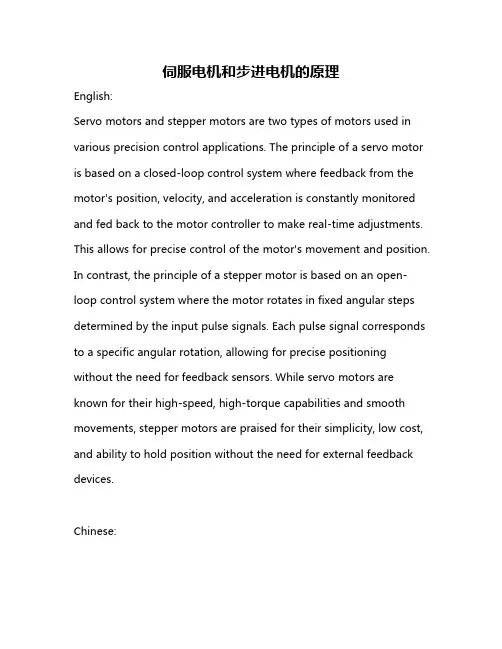
伺服电机和步进电机的原理English:Servo motors and stepper motors are two types of motors used in various precision control applications. The principle of a servo motor is based on a closed-loop control system where feedback from the motor's position, velocity, and acceleration is constantly monitored and fed back to the motor controller to make real-time adjustments. This allows for precise control of the motor's movement and position. In contrast, the principle of a stepper motor is based on an open-loop control system where the motor rotates in fixed angular steps determined by the input pulse signals. Each pulse signal corresponds to a specific angular rotation, allowing for precise positioning without the need for feedback sensors. While servo motors are known for their high-speed, high-torque capabilities and smooth movements, stepper motors are praised for their simplicity, low cost, and ability to hold position without the need for external feedback devices.Chinese:伺服电机和步进电机是用于各种精密控制应用的两种电机类型。
密级分类号编号成绩本科生毕业设计 (论文)外文翻译原文标题Stepper Motor Motion Control System Design 译文标题步进电机运动控制系统设计作者所在系别机械工程系作者所在专业机械设计制造及其自动化作者所在班级作者姓名作者学号指导教师姓名指导教师职称完成时间2012 年 2 月的个数严格成正比,在时间上与输入脉冲同步,因此只要控制输入脉冲的数量、频率及电动机绕组通电的相序,便可获得所需的转角、转速及转动方向。
在没有脉冲输入时,在绕组电源的激励下气隙磁场能使转子保持原有位置处于定位状态。
因此非常适合于单片机控制。
步进电机还具有快速启动、精确步进和定位等特点,因而在数控机床,绘图仪,打印机以及光学仪器中得到广泛的应用。
步进电动机已成为除直流电动机和交流电动机以外的第三类电动机。
传统电动机作为机电能量转换装置,在人类的生产和生活进入电气化过程中起着关键的作用。
步进电机可以作为一种控制用的特种电机,利用其没有积累误差(精度为100%)的特点,广泛应用于各种开环控制。
现在比较常用的步进电机包括反应式步进电机(VR)、永磁式步进电机(PM)、混合式步进电机(HB)和单相式步进电机等。
一步进电机的工作原理步进电机是一种用电脉冲进行控制 ,将电脉冲信号转换成相位移的电机 ,其机械位移和转速分别与输入电机绕组的脉冲个数和脉冲频率成正比 ,每一个脉冲信号可使步进电机旋转一个固定的角度.脉冲的数量决定了旋转的总角度 ,脉冲的频率决定了电机运转的速度.当步进驱动器接收到一个脉冲信号,它就驱动步进电机按设定的方向转动一个固定的角度(称为“步距角”),它的旋转是以固定的角度一步一步运行的。
可以通过控制脉冲个数来控制角位移量,从而达到准确定位的目的;同时可以通过控制脉冲频率来控制电机转动的速度和加速度,从而达到调速的目的。
二步进电机详细调速原理步进电机的调速一般是改变输入步进电机的脉冲的频率来实现步进电机的调速,因为步进电机每给一个脉冲就转动一个固定的角度,这样就可以通过控制步进电机的一个脉冲到下一个脉冲的时间间隔来改变脉冲的频率,延时的长短来具体控制步进角来改变电机的转速,从而实现步进电的调速。
Motor 电机Supply提供Connector连接口Feedback反馈CAN (Controller Area Network)总线Brushless motor无刷电机Step motor步进电机Brushless 无刷Brush 刷子Phase相位Switch转换Sensor传感器Encoder编码器power supply电源供应器supply供应AC (Alternating Current)交流电DC (direct current)直流电input power输入功率input 输入outputs 输出current 电流voltage 电压Servo伺服Driver 驱动器Logic逻辑Vector矢量Control 控制Open 打开Closed 关闭Typical Applications 典型应用Motion Control Libraries运动控制库Fully digital intelligent全数字智能graphical development environment 图形开发环境Features 特征Execute 实行Complex 复杂的Powerful强大的Suitable适用、相配的Compatible兼容的Programmable可编程的Analog模拟的Digital 数字的User manual 使用手册Family家庭New Member 新成员Dynamic torque动态转矩OPEN LOOP开环控制PPS (pulse per second)每秒脉冲数Power stage 功率电路Uni-plar单极Bi-polar双极型PM (Permanent Magnet)永久磁铁Sleeve metal 金属滑动轴承Multi-Stack 串联多级FDD (Floppy Disk Drive )软盘驱动器RM (Ring-permanent-Magnet)圆环形磁铁Sawyer 索耶Outer rotor motor 或inverted motor外转子电机Pull-out-torque 失步转矩Pull-in-torque牵入转矩Over-shoot超越角Under-shoot 返回角Setting time 稳定时间Sleeve metal滑动轴承Pre-load 预紧力Chopper 恒电流斩波器Step 步Slow up 慢下来Speed up 加速Speed速度Position位置Error误差Cogging齿槽转矩Hall sensor霍尔传感器Continuous Stall Current 持续堵转电流Maximum Mechanical Speed最大的电机转速Continuous Current额定电流Peak Current峰值电流Tuning调整Loop 环Connector Type连接类型Mating结合CONTROL SUPPLY控制电源/输入电源Table表格Protection 保护Male 男的公头Female 女的母头Provides 提供. Pin针Pinout 引出线Motion Control 运动控制Windows 窗口wall-mounted 固定在墙上absence 失去acceleration 加速accept 接受access 存取accomplish 完成,达到accuracy 准确,精确acid 酸性,酸的action 动作Active power 有功功率address 地址adequate 适当的,充分的adjust 调整,校正after 以后air 风,空气Alarm 报警Ambient 周围的,环境的Ambient temp 环境温度ammeter 电流表,安培计Ampere 安培amplifier 放大器Analog 模拟Analog input 模拟输入Angle 角度Anion 阴离子Anode 阳极,正极anticipate 预期,期望Application program 应用程序Arc 电弧,弧光Area 面积,区域Ash 灰烬,废墟assemble 安装,组装Attempt 企图Automatic AUTO 自动Auxiliary AUX 辅助的Available 有效的,可用的Avoid 避免,回避Avometer 万用表,安伏欧表计Axial 轴向的Axis 轴,轴线Axis disp protection 轴向位移,保护Axle 轴,车轴,心捧Back 背后,反向的Back up 支持,备用Back ward 向后Baffle 隔板Balance 平衡Ball 球Bar 巴,条杆base 基础、根据Base load 基本负荷Base mode 基本方式Battery 电池before 在…之前bell 铃Belt 带,皮带Black 黑色Blow 吹Blow down 排污blue 蓝色bore 孔,腔Boot strap 模拟线路,辅助程序bottom 底部brash 脆性,易脆的bracket 支架,托架,括号breadth 宽度break 断开,断路brush 电刷,刷子bucket 斗,吊斗built 建立bump 碰,撞击busbar 母线button 按钮cabinet 柜cable 电缆calculator 计算器caliber 管径、尺寸、大小calorie 卡caloric 热的、热量Caloric value 发热量、热值calorific 发热的、热量的Calorific efficiency 热效率cancel 取消、省略capacitance CAPAC 电容Capacitive reactance 容抗capacity 容量、出力、能量card (电子)板、卡cascade CAS 串级Case pipe 套管casine 壳、箱casual 偶然的、临时、不规则的cathode 阴板、负极Center 中心Chamber 办公室、会议室Change 改变Charge 负荷、充电、加注Check 检查Chest 室Chief 主要的、首长、首领Circuit 电路Circuit diagram 电路图Clamp 夹具、钳Clarification 澄清Class 类、等级、程度Clean 清洁的、纯净的Cleanse 净化、洗净、消毒Clear 清除Clockwise 顺时针、右旋的Close 关闭Closed-loop 闭环Coal 煤Coal dust 煤粉Coil 线圈Cold 冷air 大气风Collect 收集Colour 颜色Combin 合并、联合Combustion 燃烧Command 命令、指挥Commission 使投入、使投产Common 共同的、普通的Compensation 补偿Complexity 复杂Complete 完成Component 元件Compress 压缩Computer 计算机. Condensive reactance 容抗Condition 条件、状况Conduct 传导Conductivity 导电率Conference 会议、商讨、谈判Configure 组态Connection 联接Console 控制台Consult 商量、咨询、参考Consumption 消费、消耗Constant 恒定的Contact 触点Contactor 接触器、触头Contact to earth 接地、触地、碰地Content 目录Continuous 连续的Contract 合同Control CNTR/CNTPL 控制Control loop 控制环Controller 控制器Convection 对流Convertor 运输机、传输机. Cool 冷的Cooling 冷却Coordinate COORD 协调Copy 拷贝Core 铁心、核心、磁心Corner 角落Correction 修正、改正Corrosion 腐蚀Cost 价格、成本、费用Crane 起重机Critical 临界的Critical speed 临界速度Cube 立方(体)Curdle 凝固Current 电流、当前Cursor 光标Curve 曲线Custom 习惯、海关Cutter 切削工具Cyanic 青色、深蓝色Cycle 循环、周期、周波Cymometer 频率表. Damage 损坏、破坏Danger 危险、危险物Dank 潮湿Danger zone 危险区Data 数据Data base 数据库Date 日期Data pool 数据库Dead band 死区Decimeter 分米Deep 深度、深的、深Degree 度、等级Delay 延迟Delay time 延时Delete 删除Deposit 沉积结垢Description 说明、描述Destination 目标、目的地Detail 细节Detect 发现、检定Deviate 偏离、偏差Device 设备、仪器. Diagnosis 诊断Diagram 图形、图表Diameter 直径Diaphragm 膜片、隔板Dielectric 介质、绝缘的Difference 差异、差别、差额Diff press 差压Digital 数字的Digital electric hydraulic 电调Digital input/output 数字量输入/输出Dioxde 二氧化碳Direct current DC 直流(电)Disassembly 拆卸Disaster 事故、故障Disaster shutdown 事故停机Discharge 排除、放电、卸载Disk 磁盘Dispatcher 调度员Disk 磁盘Displacement 位移Display 显示、列屏Distance 距离. Disturbance 扰动Divided by 除以Design 设计、发明Division 分界、部门Division wall 分割屏Documentation 文件Door 门Dowel pin 定位销Down pipe 下降管Download 下载Downtime 停机时间Dozer 推土机Draft 通风、草图Drain pump 疏水泵Drain tank 疏水箱Drawing 图样、牵引Drill 钻孔、钻头、钻床Drive 驱动、强迫Drop 站Drum 汽包Dry 干、干燥Dust 灰尘. Duty 责任Dynamic 动态的Dynamometer 功率表Earth 大地Earth fault 接地故障Earth connector 接地线、接地Earth lead 接地线、接地Eccentricity 偏心、扰度Edit 编辑Efficiency 效率Ejection 射出Ejector 抽气器Electric 电的Elbow 弯管、弯头Electrical 电的、电气的Electrical machine 电机Electrode 电极Electronic 电子的、电子学的Electrostatic 静电的Element 元件、零件、单元Ellipse 椭圆Emergency decree 安规. Emerg off 事故停/关闭Employee 雇员Empty 排空Enclosure 外壳、包围End 末端、终结End cover 端盖Energize 激励、加电Energy 能、能量Energy meter 电度表Energy source 能源Enter 开始、使进入Entry 输入Equipment 设备Erase 删除Error 错误Event 事件Excess 超过、过度Exit 出口Expenditure 费用Expert 专家、能手Explosion 爆炸External 外部的、表面的. Extinguisher 灭火器Extend 扩展、延伸Exteral 外部的、表面的Factor 因素、因数Fahrenheit 华式温标Failure FAIL 失败FALSE 假的、错误的Fan 风扇、风机Fault 故障Features 特点Feed 馈、供给Feedback 反馈Feed forward 前馈Feed water 给水Fiber optic 光纤Field 磁场、现场Figure 数字、图案File 文件Final 最后的Fire 燃烧、火焰Fire-proof 耐火的、防火的Fire-fight 灭火. Fireproof 防火的、阻燃的First stage 第一级、首级Flame 火焰Flank 侧翼、侧面Flash lamp 闪光灯Flash light 闪光Flasher 闪光装置Flexible 灵活的、柔性的Flow 流量、流动Flue 烟道Format 形式、格式Follow 跟随Forbid 禁止Force 强制Forward 向前Free end 自由端Frequency 频率From 从、来自Front 前面的Fuel 燃料Fully 充分的、完全的Function 功能. Fuse 保险丝、熔断器Fuse holder 保险盒Gate 闸门Gateway 入口、途径Gauge 仪表、标准Gear 齿轮Generate 引起、产生Generator 发电机、发生器Gland 密封套Gland seal 轴封Goal 目的、目标Go on 继续Grease 图形Green 绿色Ground/earth 地、大地Group 组、群Hardware 硬件Hazardous 危险的、冒险的Hertz HZ 赫兹History 历史Hold 保持Home 家、处所Horse power 马力Hot 热的Hot air 热风Hour 小时Idiostaic 同电位的Idle 空载的、无效的Ignore 忽视Illustrate 说明Impedance 阻抗Import 进口、引入Impulse 脉冲、冲击、冲量Inch IN 英寸Index 索引、指示Indicator 指示器Individual 单个的、独立的Inductive reactance 感抗Input/output I/O 输入/输出Inductance 电感Induction motor 异步电动机Industry 工业Inhibit 禁止Initial 最初的Inlet 入口Input group 输入组Insert 插入Inside 内侧、内部Inspection 观察、检查Install 安装Instruction 说明书、指南、指导Instrument 仪器Insulator 绝缘子Intake 输入端、进线Integer 整数Integral 积分Intensity 强度Interface 接口Interference 干扰、干涉Interlock 联锁Intermediate 中间的Internal 内部的Interrogation 质问、问号Interval 间隔Invoice INV 发票、发货单、托运Invalid 无效的、有病的Isolation 隔离Job 工作Jumper 跳线、跨接Key 键销、钥匙、键槽Keyboard 键盘Kilovolt-ampere KVA 千伏安Kink 弯曲、缠绕Knack 技巧、窍门、诀窍Label 标号、标签Laboratory 实验室Ladder 梯子、阶梯Ladder diagram 梯形图Lamp 灯、光源Last 最后的Leak 泄漏(动词)Leakage 泄漏(名词)Left 左Length 长度Level 液位、水平Lifebelt 安全带、保险带Lift 提、升Light 光亮、点、点燃、照亮. Lightning 雷电Light run 空转Lightning arrestor 避雷器Limit LMT 极限、限制Limiter 限制器、限位开关Line 线、直线impedance 线路阻抗Linkage 连杆List 列表Liter 公升Load 负荷limit 限制Loading 加负荷Local 局部Lock 闭锁、密封舱、固定Logic 逻辑Long 长Loop 环、回路Loss 损失、减少Loss of excitation 励磁损失Loss of phase 失相Low 低Low-half 下半Lower 较低的、降低Lub oil 润滑油Magenta 品红色Magnet 磁Main steam 主蒸汽Make up 补充(补给)Makers works 制造厂Malfunction 出错、误动、失灵Management 管理、控制、处理Manhole 人孔、检查孔、出入孔Manometer 压力表Manual 手动、手册Mark 型号、刻度、标志、特征Mass memory 大容量存储器Master 主要、控制者Maximum 最高的、最大Mean 平均值、中间的Measure 量度、测量Mechanical 机械的、力学的Mechanism 机械、力学、方法Medial 中间的、平均的Mediate 间接的、调解Medium 装置、介质、工质Memory 存储Metal 金属Meter 集量器、仪表、米Method 方法、规律、程序Method of operation 运行方式Mica 云母Microcallipers 千分尺Middle MID 中间的Minimum 最小的Minus 减、负号Minus phase 负相位Minute 分钟Miss operation 误动作、误操作Mistake 错误、事故Mixture 混合物Modify 修改Modulating control 调节控制Module 模件Moisture 湿度、湿汽Monitor 监视器、监视. Mount 安装、固定Mountain cork 石棉Mouse 鼠标Move 移动Multimeter 万用表Multiplication 乘Name 名、名字Natural 自然的Naught line 零线Negative 负的Neon tester 试电表Network 网络Neutral 中性的Neutral point 中性点Next 其次的Nipper 钳子、镊子Noise 噪音No-loading 空载Nominal power 额定功率Non-work 非工作的Normal 正常的、常规的Not available 无效、不能用Number 数字、号码、数目Number of turns 匝数Nut 螺母、螺帽Occur 发生Odd 奇数Office 办公室Oil 油On/off 开/关Onset 开始、发作Open 开、打开Open-air 露天的、开启的Open-loop 开环Open work 户外作业Operation 操作、运行Operational log 运行记录Operator 操作员Optimal 最优的、最佳的Optimal value 最佳值Optional 可选的Option switch 选择开关Original 初始的、原始的Out 出、出口Outage 停用Outlet 出口Output 产量、产品、输出Outside 外边、外面Over current 过流Over load 过负荷Overload protection 过载保护Over voltage 过压Overflow 溢流Overhead 顶部Override 超越Overspeed 超速Overview 概述、总述Oxygen 氧Pad 瓦、衬垫Page 页Panel 屏、盘Parameter 参数Part 部分、部件Password 口令Path 路线Peak 峰值Pendant 悬吊Perfect 完全的、理想的Performance 完成、执行、性能Periodic 周期的、循环的Peripheral 周围的Permanent 永久的、持久的Permit 允许Petrol 汽油Phase PH 阶段、状态、方面、相Phase angle 相角Phase not together 缺相、失相Phase sequence 相序Phase-in 同步Piezometer 压力计Pilot 导向、辅助的、控制的Pilot bearing 导向轴承Pipe 管、管道Plan 计划Plant 工场、车间Plastics 塑料Plug 塞子、栓、插头Plug socket 插座Plus 加Plyers 钳子、老虎钳Point 点Phase voltage 相电压Pole 机、柱Pollution 污染Pop valve 安全阀、突开阀Portion 一部分Position POS 位置Positive 确定的、正的、阳性的Potable water 饮用水Pound LB 磅Power PWR 功率、电源Power factor 功率因子Power plant 电厂Preliminary 准备工作Present 出现Preset 预设、预置Pressure PRES 压力Primary 初级的、一次的Prime 首要的Printer 打印机Principle 原理、原则Priority 优先级、优点Probe 探头Process 过程、方法Processing time 处理时间Program 程序Programmable 可编程的Prohibit 禁止Protection PROT 保护Potential transformer PT 电压互感器Psig 磅/平方英寸(表压力)Psia 磅/平方英寸(绝对压力)Pulse 脉冲、脉动Pump 泵Purge 净化、吹扫Purify 纯度Purpose 目的、用途Push button 按钮Put into operation 投入运行Pyrology 热工学Q-line Q线Quad 回芯组线Quality 质量Quartz 石英、水晶Query 询问、查询Quick 快Quick open 快开Quit 停止、离开、推出Rack earth 机壳接地Radial 径向的、半径的Radication 开方Radiation fin 散热片Raise 升高Range 范围、量程Rap 敲打Rapid charge 快速充电Rated 额定的、比率的Rated conditions 额定条件Rated power 额定功率Ratio 比率Raw material 原材料Ray 光线、射线Reactance 电抗、反作用Reactive capacity 无功容量Reactive power 无功功率Ready 准备好Real power 有效功率Real time 实时的Rear 后面Recipe 处方、配方Recirculate 再循环Recovery 恢复、再生Rectifier 整流器Red 红色Reduction 还原、缩小、降低Reference REF 参考、参照、证明书Reflux 倒流、回流Region 地域、领域Regulate 调节、控制Relative REL 相对的Release 释放Reliability 可靠的、安全的Relief 去载、卸载、释放、解除Renewal 更新、更换Repair 修理Repairer 修理工、检修工Repeat 重复、反复Replacement parts 备件、替换零件Request REO 请求Require 要求Reserve parts 备件Reserved 备用的Reset 复位Resistance 阻力、电阻Resonate 谐振、调谐Response 响应Return 返回Reverse rotation 反转Review 检查Rig 安装、装配、调整Right 右Ring 环Root 跟Rotating 旋转Rotor 转子Run 运行Run back 返回Safe 安全的、可靠的、稳定的. Safe potential 安全电压Safety 安全Saturate 饱和Scan 扫描Screw 螺杆、螺丝Screwdriver 螺丝刀Sea 海Search 寻找、查找Second 秒、第二Seep 渗出、渗漏Select 选择Sensor 传感器Sensitive 灵敏器Sequence 顺序、序列Service 服务、伺服Servomotor 伺服电机Set 设定Set up 安装、调整、建立Shadow 影子、屏蔽Shake 摇动、振动Shaped 形状Share 共享、分配. Sheet 表格、纸张Shell 壳Short circuit 短路Shot 发射、冲击、钢粒Shut off 关闭Shutdown 停止、停机Side 侧边Sidewall 侧墙Signal 信号Sign 标记、注册Silicon SI 硅Silo 灰库Single 单个的、个体的Simple 单纯的、简单的Similar 同样的、类似的Simulator 仿真机Site 现场Size 尺寸、大小Soft 软的、柔软的Software 软件Solid 固体Source 源、电源. Speed 速度Square 广场、方的Stability 稳定(性)Standard 标准Start 启动、开始Start up 启动State 状态Static 静电Stator 静子Stator coil 定子线圈Stator core 定子铁芯Status 状态Steadiness 稳定性Step 步Stere 立方米Stop 停止Storage 储存Straight 直的、直线Subject 题目、科目Supply 供给Support 支持、支撑Sure 确信的、可靠的System 系统Tab 表格Tandem 串联Tank 箱Tap 抽头、分布Target 目标Temperature 温度Template 模板、样板Tensile 拉力的、张力的Text 出口Terminal 端子、接线柱Test 试验Thermal 热的/热量的/由热驱动的Thermal conduction 热传导Thermal convection 热对流Thermal couple 热电偶Thermal cycle 热力循环Thermal radiation 热辐射Thermometer 温度计Thickness 厚度、浓度Third 第三Throttle 节流Thumb rule 安培右手定则Tight 紧密的Tilt 倾斜Tilting 摆动Title 题目、标题Total 总计的To 到、去Token 标志Tool 工具Tool box 工具箱Torque 扭矩、力矩Track 跟踪Travel 过程、运转、进行、移动Trend 趋势、方向Trip 跳闸、断开Trouble 事故、故障、干扰True 真实的、调整、校正TUNE 调节Tuning 调谐Tweezers 镊子、钳子Type 类型、标志Unbuild 失磁. Unit 单元、机组、电池Unload 减负荷Unlock 打开、解锁、释放Unprotected 未保护的、无屏蔽的Up 向上Up-half 上部、上半Update 更新、修改、校正Upgrade 升级(优先级)提高/改进Upper 上部Use 使用User 用户Valid 有效地、正确Value 数值Variable 可变的、可调的Vector 失量、向量Vessel 容器Vibration 振动Voltage transformer 电压互感器Voltmeter 电压表Volume 容积、体积Wall 墙、壁Wash 洗. Weather 天气Weak 星期、周Weight 重量Weld 焊接White 白色Windbox 风箱Windings 绕组Windows 窗口Wire 电绕Wire stripper 剥线钳Wood 木、木制的Work 工作Year 年Yellow 黄色Zero 零Zone 区、层、带。
步进电机的的基本原理中英文翻译English translation of the stepping motor basic principle步进电机作为执行元件,是机电一体化的关键产品之一,广泛应用在各种自动化控制系统中。
随着微电子和计算机技术的发展,步进电机的需求量与日俱增,在各个国民经济领域都有应用。
The stepping motor as executing components, electromechanical integration is one of the key products, widely used in a variety of automatic control systems. With the development of microelectronics and computer technology, the stepper motor demand grow with each passing day, has been applied in various fields of the national economy.步进电机是一种将电脉冲转化为角位移的执行机构。
当步进驱动器接收到一个脉冲信号,它就驱动步进电机按设定的方向转动一个固定的角度(称为“步距角”),它的旋转是以固定的角度一步一步运行的。
可以通过控制脉冲个数来控制角位移量,从而达到准确定位的目的;同时可以通过控制脉冲频率来控制电机转动的速度和加速度,从而达到调速的目的。
步进电机可以作为一种控制用的特种电机,利用其没有积累误差(精度为100%)的特点,广泛应用于各种开环控制。
Stepping motor is a kind of electrical pulses into angular displacement of the implementing agencies. When stepping drive receives a pulse signal, it drives stepper motor rotate in the direction set by a fixed angle ( called the " step " ), it is the rotation at a fixed angle step by step operation. The number of pulses to control the amount of angular displacement through the control, so as to achieve the purpose of accurate positioning; also can control the pulse frequency to control motor rotation speed and acceleration, so as to achieve the purpose of speed. Special motor stepper motor control can be used as a, using its no accumulation of error ( accuracy of 100% ) characteristics, widely used in all kinds of open-loop control.现在比较常用的步进电机包括反应式步进电机(VR)、永磁式步进电机(PM)、混合式步进电机(HB)和单相式步进电机等。
译文伺服电机原理及应用电机是如何工作的电动机是将电能转换成机械运动,电机用在家用电器,电动风扇,遥控玩具等各种使用场合电机起源于早期电学上的一个发现- Arago转动.在1824年, Francois Arago发现悬浮在铜盘上的磁针,在铜盘转动时也跟着转动.第二年,计算机先驱Charles Babbage和天文学家John Herschel向人们展示上述运动可以相逆的:转动一块位于铜盘上方较强的磁铁时,铜盘也转动.在1831年, Michael Faraday通过试验来解释这一现象发生的原因.在电机实际运用前,半个多世纪来做这些电机些基础研究过了几十年后,许多发明家不断改进发明将电能转换成机械能.其中一个就是1832 Hippolyte Pixii改进了之后称为换向器的发明.它通过改变位于两个或更多的固定电磁石电流方向,以维持一台电机连续运转. Thomas Davenport是第一个制造出在工业中使用的电机.并是第一个对电机申请专利的.不久电机被用作诸如交通运输等场合. Moritz-Hermann De Jacobi将一台电机安装在涅瓦河上的一条船上. Charles G. Page用电机做了一台小型机车.伴随着19世纪80年代商业性电力供应系统出现,制造出更大的电机也变得有可能. Edison鼓励在工业中便用电机,并且设计了几一些为工业使用兵新型电机在19世纪80年代到90年代发生了一个重大变化,电力公司开始考虑转成交流电.交流适合于长距离传输.并且在Edison的电灯上工作的很好,但是没有实际的交流电机存在,直到意大利的Galileo Ferraris和美国的Nikola Tesla. 在今天人们认为Tesla的贡献比Ferraris大部分原因是前者后来受雇于西屋公司,这家公司应用了他自己的及其他人的专利,成了为电气设备一个主要的生产者.随着交流电机成为可能,交流电力的发展,交流电机一直使用到现在。
电动机控制中英文对照外文翻译文献(文档含英文原文和中文翻译)原文:Control of Electric winchFor motor control, we know the best way is to use the style buttons to move the many simple manual console. And this console, in some applications may still be a good choice, as some complex control headache can also be used. This article describes in your design, build or purchase winch controller, you have the motor's basic electrical equipment and you will need to address the user interface command addressed.First, the manual should be a manual control console type, so if you remove your finger buttons, hoist will stop. In addition, each control station equipped with an emergency need to brake, hoist the emergency brake to cut off all power, not just the control circuit. Think about it, if the hoist at the stop, it did not stop, you do need a way to cut off the fault line protection power. Set the table in the control of a key operated switch, is also a very good idea, especially in the line leading to theworkstation can not control, you can use the switch.(in the design of the console, even the simplest manual console, but also consider setting by specialized personnel to operate the safe operation of the keys.) Constant speed motor controlFor a fixed speed winch actual control device is a three-phase starter. Turn the motor is reversed, by a simple switch controlled phase transformation sequence from ABC to CBA. These actions are completed by two three-pole contactor-style, and they are interlocked, so that they can not be simultaneously closed. NEC, required in addition to overload and short circuit protection devices. To protect the motor against overload due to mechanical effects caused by overheating in the heat to be installed inside the starter overload delay device. When the heat overload delay device overheating, it has a long double off the metal motor power. In addition In addition, you can also select a thermistor can be installed in the motor winding way, it can be used to monitor motor temperature changes. For the short-circuit protection, we generally used by motor fuses to achieve.A linear current independent contactors, the contactors are configured should be more than the current main circuit contactor, so as to achieve the purpose of redundancy. This sets the current contactor is controlled by the security circuit, such as: emergency brake and the more-way limits.We can use the limit switches to achieve the above operation. When you reach the end of the normal travel limit position, the hoist will stop, and you can only move the winch in the opposite direction (ie, the direction away from the limit position.) There is also need for a more limited way just in case, due to electrical or mechanical problems, leaving the operation of hoist limit bit more than normal. If you run into more limiter, linear contactor will open, therefore, can not be driven winch will exceed this limit position. If this happens, you need to ask a professional technician to check the lead to meet the more specific reasons limiter. Then, you can use thestarter toggle switch inside the elastic recovery process to deal with more problems, rather than tripping device or a hand-off the current contacts.A necessary condition for speedOf course, the simple fixed speed starter is replaced by variable speed drives. This makes things start to get interesting again! At a minimum, you need to add a speed control dial operation platform. Joystick is a better user interface, because it makes you move parts of a more intuitive control.Unfortunately, you can not just from your local console to send commands to control the old variable speed drives, in addition, you can not want it in the initial stages, will be able to enhance the safe and reliable and decentralized facilities. Most of the variable speed drive can not achieve these requirements, because they are not designed to do upgrading work. Drivers need to be set to release the brake before the motor can generate torque, and when parking, that is, before the revocation of torque, the brake will be the first action.For many years, DC motors and drives provide a number of common solutions, such as when they are in a variety of speeds with good torque characteristics. For most of the hoist of the large demand for DC motor is very expensive, and that the same type of AC motor than the much more expensive. Although the early AC drives are not very useful, as they have a very limited scope of application of the speed, but produced only a small low-speed torque. Now, with the DC drives the development of low cost and a large number of available AC motors has led to a communication-driven revolution.Variable speed AC drives in two series. Frequency converter has been widely known and, indeed, easy to use. These drives convert AC into DC, and then, and then convert it back to exchange, the exchange after the conversion is a different frequency. If the drive produced the exchange of 30Hz, 60Hz a normal motor will run at half speed. Theoretically, this is very good, but in practice, this will have a lot of problems. First of all, a typical linear motor 60Hz frequencies below 2Hz 3Hz area or there will be errors, and start cog (that urgent push, yank), or parking. This will limit your speed range lower than 20:1, almost not adapted to the operational phase of the fine adjustment. Second, many low-cost converter is not able to provide the rated torque at low speeds. Use of these drives, will result in the rapid move to upgrade the components or complete failure, precisely, when you try to upgrade a stable scientific instruments, you do not want to see this situation. Some new inverter is a closed-loop system (to get feedback from the motor to provide a more accurate speed control), and the motor will work quite well.Another series of AC drives is the flow vector type drive. These components require installation of the spindle motor encoder, encoder makes use of these drivescan accurately monitor the rotation of the motor armature. Processor accurately measured magnetic flux vector values that are required to make the armature at a given speed rotation. These drives allow infinite speed, so you actually can produce at zero speed to rated torque. These drives provide precise speed and position control, so these drives in high performance applications to be welcomed.(Based on PLC controllers provide system status and control options. This screen shows the operator full access to the nine-story elevator enhance the control panel.) PLC-based systemsIs the full name of a PLC programmable logic controller. First of all, PLC controller developed to replace the fifties and sixties-based industrial control system relay, they work in harsh industrial indoor environments. These are modular systems that have a large variety of I / O modules. The modular system can easily achieve the semi-custom hardware configuration assembled, and the resulting configuration is also very reasonable price. These modules include: position control module, the counter, A / D and D / A converter, and a variety of physical state or physical contact with closed output module. Large number of different types of I / O components and PLC module property makes it an effective way to assemble custom and semi custom control system.The biggest shortcoming of PLC systems is the lack of the real number of display to tell you what is being done and the PLC on the PLC program to help you.T he first is professional entertainment for the large-scale PLC system is one of the original in Las Vegas, MGM (now Bailey Company) of the riding and carriage system. Many manufacturers offer a standard PLC-based semi-automated acoustic systems and a host of signs, set the location of the command line interpreter, and the upgrading of the control system is also available. Using standard modules to set user-defined system configuration capability is based on the PLC controller of the greatest advantage.High-end controllerFor complex transmission, the controller became complex, more than speed, time and location control. They include complex instructions to write and record the movement contour, and the processing can immediately run the ability to multi-point instructions.Many large opera house is toward the direction of point lift system, where each one is equipped with a rope to enhance independent winches, rope equivalent to those of each dimmer circuit. When more than one hoist is used to enhance the individual part, the hoist must be fully synchronous, or the load to shift, so will lead to a separate winch becomes the risk of overload. Control system must be able to be selected to keep pace winch, or a hoist winch is not able to maintain synchronization with the other, can provide the same high-speed parking capacity. For a typical speed of 240 ft / min and a winch to maintain the rate of error of between 1 / 8 points of equipment, you only have less than three microseconds of time to identify problems and try to correct the error The hoist speed, make sure you fail, you start all the winch stop the group. This will require a large amount of computation, fast I / O interface, and easy to use to write software.For large rope control system has two very different solutions. The first is to use a separate console, the problem in general terms, this console should be installed in the appropriate location of the operator perspective. However, this not only from one angle to another angle, but still can not get an instruction to another instruction from the control. These difficulties have been partially resolved. Installed in different locations through the use of video cameras, and these cameras connected to the three-dimensional display graphics, these graphics enables the operator to observe from the perspective of any of the three coordinates in the expected direction of rope movement. These operators can make from a console for him at the actual angle, or closed circuit camera practical perspective, to observe the movement of the rope on the screen. For the complex interrelated moving parts, makes the implementation of the above observation Failure to control and find out easier.Another solution to the problem is a distributed system that uses multiple light console. This will allow the different operators in the same way the different aspects of control gear, we have improved the manual control device. A vivid example is the flower in a vegetable market in central London, the Royal Opera House, the program uses the above, where the control console 240 with ten motors. Each console has five playback device, and has been open, so that each motor has been assigned to a single console. An operator and a console can control all the devices, however, often may be running a console platform screen upgrade, another console is a console on the transmission device, and the third console is used to the necessary backgroundin the background image down.(edge-type portable console allows the operator many advantages from the start to control the movement of the machine, and provide three-dimensional image display.)ConclusionA huge change in the rope control system, a workstation has been developed from a push-button to complex multi-user computerized control system. When the control system to buy rope, you can always find to meet your needs. Control system performance is the most important security and reliability. These are the true value of the property, and you can expect the price to buy a suitable way of security. With a certain product manufacturers to work, he will make you know how to install it. And he will make contact with you and the users, those users have with similar requests.译文:电动卷扬机的控制对于电动机的控制,我们所知道的最好的方式就是使用由许多点动式按钮组成的简单的手工操作台。
中英文对照外文翻译文献(文档含英文原文和中文翻译)The shallow treads into the PLC control technique and development trend of electrical engineering1. Say all:Along with the micro-electronics technique and the calculator technical hair Exhibition, the programmable preface controller has an advance by leaps and bounds of hair Exhibition, its function has already outrun a logic control far and far, in proper order The scope of control, it has an effect to combine with calculator, can enter Go to imitate to control most, have along range correspondence function etc.. Have-The person is called it the modern D industry controls of three pay pillar greatly(namely PLC, robot, CAD/CAM)it a, currently programmable controller BE applied in metallurgy extensively, Mineral industry, machine, light Class D realm, automate for the industry Provided to there is the tool of one dint The PLC controls of tread to open the wreath servo organization into the electrical engineering should Used for combining tool machine to produce an on-line number to control a slippery pedestal to control automatically Make, can the province go to the number of that unit to control system, making that unit The cost of controlling the system lowers.2、What is a stepper motor:Stepper motor is a kind of electrical pulses into angular displacement ofthe implementing agency. Popular little lesson: When the driver receives a step pulse signal, it will drive a stepper motor to set the direction of rotation at a fixed angle (and the step angle). You can control the number of pulses to control the angular displacement, so as to achieve accurate positioning purposes; the same time you can control the pulse frequency to control the motor rotation speed and acceleration, to achieve speed control purposes.What kinds of stepper motor sub-:In three stepper motors: permanent magnet (PM), reactive (VR) and hybrid (HB) permanent magnet stepper usually two-phase, torque, and smaller, step angle of 7.5 degrees or the general 15 degrees; reaction step is generallythree-phase, can achieve high torque output, step angle of 1.5 degrees is generally, but the noise and vibration are large. 80 countries in Europe and America have been eliminated; hybrid stepper is a mix of permanent magnet and reactive advantages. It consists of two phases and the five-phase: two-phase step angle of 1.8 degrees while the general five-phase step angle of 0.72 degrees generally. The most widely used Stepper Motor. What is to keep the torque (HOLDING TORQUE)3、Tread into the basic characteristics of electrical engineering:(1)、tread generally into the accuracy of the electrical engineering for tread into Cape of 3-5% and don't accumulate.(2)、tallest temperatures which enter electrical engineering outward appearance and allow tread and lead into the electrical engineering temperature high can make the magnetism material of electrical engineering back first, cause the dint descend thus is as for lose a step, so the electrical engineering outward appearance allow of the tallest temperature should be decided by small back with electrical engineering magnetism material and order; Speak generally, the magnetism material backs to order all above have in 130 C an of even be up to 200C above, so tread completely normal into the electrical engineering outward appearance temperature in 80-90C.(3)、dints which enter electrical engineering would with turn to go up but descend soon,While treading to turn to move into the electrical engineering,electrical engineering each electricity feeling which round a set mutually will become one anti- to electromotive force; The frequency is more high, anti- to electromotive force more big ,big in its function, the electrical engineering enlarges with the frequency(or speed) but mutually the electric current let up, causing the dint descend thus.(4)、can revolve normally when 4 enter electrical engineering low speed, but if high in certain the speed can't start, and the companion have a roar the interjection tread to have a technique parameter into the electrical engineering: empty carry start frequency, then tread into electrical engineering at empty carry under circumstance can start normally of pulse frequency, if the pulse frequency is high in should be worth., The electrical engineering can't start normally, the possible occurrence throws a step or blocks up to turn. Under the situation that there is one load, the start frequency should be much lower if want to make the electrical engineering attain high speed to turn to move, the pulse frequency should have an acceleration process, then start the frequency is lower, then press certain acceleration to rise the high hoped. Tread to show the characteristics of with it into the electric motor, turn ages of manufacturing to develop important use to accompany with in the numeral small together of numeral turn technical of development and tread into the electrical engineering technical exaltation,tread will get an application in more realms into the electrical engineering.4、enter an electrical engineering control system to constitute:Tread is a kind of performance organization that will give or get an electric shock a pulse conversion to move for the Cape into the electrical engineering. When tread to receive to a pulse signal into the actuator, it drives a step to press the direction of enactment to turn to move an angle for fixing to be called "tread to be apart from Cape" into the electrical engineering, it revolves one-step circulate with the fixed angle one step. Can pass control pulse piece to control a Cape to move to attain the purpose of assurance most and thus; Can pass control pulse frequency to control electrical engineering to become dynamic speed and acceleration in the meantime, the purpose attained to adjust thus soon treads into the electrical engineering. Can be the special kind electrical engineering that a kind of control uses, make use of it didn't accumulate error margin accuracy to 100 to divide 100 of characteristics, be suffused with to apply in various open a wreath control PLC which enter electrical engineering technique.5、Stepper motor of the PLC control technology:Make the importation tread to be subjected to a homologous control into total amount and pulse frequency of the importation pulse of electrical engineering. Establish the pulse signal occurrence that a pulse total amount and pulse frequency can control a machine therefore and in control,software; Can make use of PL in fixed time a machine composing for the frequency lower control pulse, the pulse frequency can pass in fixed time machine in fixed time constant control pulse period, the pulse amounts control then can establish a the pulse counter C10 be when the pulse number attain initial value, count machine C1.The action cuts off pulse back track, making it stop, the servo organization tread into the electrical engineering have no the pulse input then stop operation,servo performance organization fixed position be servo performance organization of when move speed to have higher request, can use PLC high-speed pulse,Different PLC it the frequency of high-speed pulse can reach to 4000-6000Hzses. The PLC is used to produce control pulse, passing PLC plait distance exportation several pulses certainly the control treads to turn Cape into the electrical engineering, programmable controller output's control the pulse enters electrical engineering to switch on electricity sequence to assign by the step homologous of round a set. The PLC controls of tread can go an allotment machine by adoption software wreath into the electrical engineering, the hardware wreath goes allotment machine to adopt the PLC resources that the soft wreath takes up more, Tread especially to round a set to count mutually into the electrical engineering big should consider adoption hardware wreath to go allotment machine well for large production line at 4, although the hardware structure is a little bit a little more complicated, can save an exportation importation of taking up the PLC point, the market has a various appropriation chips to choose to use currently. Tread to enlarge to several ten highest hundred folds into the output's control of the actuator PLC of the electrical engineering power pulse, volt, several Anne arrive several ten several Anne s drive an ability, the exportation of general PLC connects to have to certainly drive an ability, but inside usual transistor flow exportation to connect an ability only for ten several arrive several ten volts, several ten arrive several 100 million Anne but tread to then have several request into the electrical engineering to the power ten arrive up 100 volts, several Anne arrive several ten Anne s drive an ability so should adopt an actuator to output the pulse carry on enlarging.6、Application features of PLC(1)、High reliability, strong anti-interferenceHigh reliability is the key to performance of electrical control equipment. PLC as the use of modern large scale integrated circuit technology, using the strict production process, the internal circuits to the advanced anti-jamming technology, with high reliability. Constitute a control system using PLC, and the same size compared to relay contactor system, electrical wiring and switch contacts have been reduced to hundreds or even thousands of times, fault also greatly reduced. In addition, PLC hardware failures with self-detection, failure alarm timely information. In the application software, application are also incorporated into the peripheral device fault diagnosis procedure, the system is in addition to PLC circuits and devices other than the access protection fault diagnosis. In this way, the whole system extremely high reliability.(2)、Fully furnished, fully functional, applicabilityPLC to today, has formed a series products of various sizes, can be used for occasions of all sizes of industrial control. In addition to processing other than logic, PLC data, most of computing power has improved, can be used for a variety of digital control in the field. A wide variety of functional units in large numbers, so that penetration to the position of PLC control, temperature control, CNC and other industrial control. Enhanced communication capabilities with PLC and human-machine interface technology, using the PLC control system composed of a variety of very easily.(3)、Easy to learn, well engineering and technical personnel welcome PLC is facing the industrial and mining enterprises in the industrial equipment. It interfaces easily, programming language easily acceptable for engineering and technical personnel. Ladder language, graphic symbols and expressions and relay circuit very close to are not familiar with electronic circuits, computer principles and assembly language do not understand people who engage in industrial control to open the door.(4)、System design, the workload is small, easy maintenance, easy to transformPLC logic with memory logic instead of wiring, greatly reducing the control equipment external wiring, make the control system design and construction of the much shorter period, while routine maintenance is also easier up, even more important is to change the procedures of the same equipment has been changedproduction process possible. This is particularly suitable for many varieties, small batch production situations.7、The development trend of 5 domestic and international electrical engineering: (1)、continue along small scaled direction development turned along with electric motor application the realm open widely and each kind of whole machine is continuously small scaled to turn, the electric motor which requests with its kit have to also more and more small, at 57, the electric motor of 42 machine seat numbers applies many after years, now its machine seat number to 39,35,30,25 directions get down extension.(2 )、right nesses of electric motors carry on comprehensive design namely turn soon position to spread a feeling machine, decelerate the wheel gear etc. and electric motor essence to synthesize design together, so make it be able to constitute 1 to shut wreath system expediently, as a result have one more superior control function.(3)、to five mutually with three mutually the electric motor direction develop,Be suffused with currently applied of two mutually with four mutually the electric motor, its vibration and voice are bigger, but five mutually with three mutually the electric motor have advantage but in regard to these two kinds of electric motors, five mutually the electric motor drive electric circuit compare. 8、Conclusion:At present, the use of programmable process controller (that is, the PLC technology) can easily realize the control of motor speed and the position of the convenient, c onvenient for a variety of stepper motor operation, t o complete a variety of complex work. It represents the advanced industrial automation revolution; accelerate the realization of the electromechanical integration.浅析步进电机的PLC控制技术与发展趋势1、概述随着微电子技术和计算机技术的发展,可编程序控制器有一了突飞猛进的发展,其功能已远远超出了逻辑控制、顺序控制的范围,它与计算机有一效结合,可进行模拟最控制,具有一远程通信功能等。
Step Motor&Servo Motor Systems and ControlsMotion Architect® Software Does the Work for You... Configure ,Diagnose, Debug Compumotor’s Motion Architect is a Microsoft® Windows™-based software development tool for 6000Series products that allows you to automatically generate commented setup code, edit and execute motion control programs, and create a custom operator test panel. The heart of Motion Architect is the shell, which provides an integrated environment to access the following modules.• System Con figurator—This module prompts you to fill in all pertinent set-up information to initiate motion. Configurable to the specific 6000 Series product that is selected, the information is then used to generate actual 6000-language code that is the beginning of your program.• Program Editor—This module allows you to edit code. It also has the commands available through “Help” menus. A user’s guide is provided on disk.• Terminal Emulator—This module allows you to interact directly with the 6000 product. “Help” is again available with all commands and their definitions available for reference. • Test Panel—You can simulate your programs, debug programs, and check for program flow using this module.Motion Architect® has been designed for use with all 6000 Series products—for both servo and stepper technologies. The versatility of Windows and the 6000 Series language allow you to solve applications ranging from the very simple to the complex.Motion Architect comes standard with each of the 6000 Series products and is a tool that makes using these controllers even more simple—shortening the project development time considerably. A value-added feature of Motion Architect, when used with the 6000 Servo Controllers, is its tuning aide. This additional module allows you to graphically display a variety of move parameters and see how these parameters change based on tuning values.Using Motion Architect, you can open multiple windows at once. For example, both the Program Editor and Terminal Emulator windows can be opened to run the program, get information, and then make changes to the program.On-line help is available throughout Motion Architect, including interactive access to the contents of the Compumotor 6000 Series Software Reference Guide.SOLVING APPLICATIONS FROM SIMPLE TOCOMPLEXServo Control is Yours with Servo Tuner SoftwareCompumotor combines the 6000 Series servo controllers with Servo Tuner software. The Servo Tuner is an add-on module that expands and enhances the capabilities of Motion Architect®.Motion Architect and the Servo Tuner combine to provide graphical feedback ofreal-time motion information and provide an easy environment for setting tuning gains and related systemparameters as well as providing file operations to save and recall tuning sessions.Draw Your Own Motion Control Solutions with Motion Toolbox Software Motion Toolbox™ is an extensive library of LabVIEW® virtual instruments (VIs) for icon-based programming of Compumotor’s 6000 Series motion controllers.When using Motion Toolbox with LabVIEW, programming of the 6000 Series controller is accomplished by linking graphic icons, or VIs, together to form a block diagram. Motion Toolbox’s has a library of more than 150 command,status, and example VIs. All command and status VIs include LabVIEW source diagrams so you can modify them, if necessary, to suit your particular needs. Motion Toolbox als user manual to help you gut up and running quickly.comprehensiveM Software for Computer-Aided Motion Applications CompuCAM is a Windows-based programming package that imports geometry from CAD programs, plotter files, or NC programs and generates 6000 code compatible with Compumotor’s 6000 Series motion controllers. Available for purchase from Compumotor, CompuCAM is an add-on module which is invoked as a utility from the menu bar of Motion Architect.From CompuCAM, run your CAD software package. Once a drawing is created, save it as either a DXF file, HP-GL plot file or G-code NC program. This geometry is then imported into CompuCAM where the 6000 code is generated. After generating the program, you may use Motion Architect functions such as editing or downloading the code for execution.Motion Builder Software for Easy Programming of the 6000 SeriesMotion Builder revolutionizes motion control programming. This innovative software allows programmers to program in a way they are familiar with—a flowchart-style method. Motion Builder decreases the learning curve and makes motion control programming easy.Motion Builder is a Microsoft Windows-based graphical development environment which allows expert and novice programmers to easily program the 6000 Series products without learning a new programming language. Simply drag and drop visual icons that represent the motion functions you want to perform.Motion Builder is a complete application development environment. In addition to visually programming the 6000 Series products, users may configure, debug, download, and execute the motion program.SERVO VERSUS STEPPER... WHAT YOU NEED TOKNOWMotor Types and Their ApplicationsThe following section will give you some idea of the applications that are particularly appropriate for each motor type, together with certain applications that are best avoided. It should be stressed that there is a wide range of applications which can be equally well met by more than one motor type, and the choice will tend to be dictated by customer preference, previous experience or compatibility with existing equipment.A helpful tool for selecting the proper motor for your applicat ion is Compumotor’s Motor Sizing and Selection software package. Using this software, users can easily identify the appropriate motor size and type.High torque, low speedcontinuous duty applications are appropriate to the step motor. At low speeds it is very efficient in terms of torque output relative to both size and input power. Microstepping can be used to improve smoothness in lowspeed applications such as a metering pump drive for very accurate flow control.High torque, high speedcontinuous duty applications suit the servo motor, and in fact a step motor should be avoided in such applications because the high-speed losses can cause excessive motor heating.Short, rapid, repetitive movesare the natural domain of the stepper due to its high torque at low speeds, goodtorque-to-inertia ratio and lack of commutation problems. The brushes of the DC motor can limit its potential for frequent starts, stops and direction changes.Low speed, high smoothness application sare appropriate for microstepping or direct drive servos.Applications in hazardous environmentsor in a vacuum may not be able to use a brushed motor. Either a stepper or a brushless motor is called for, depending on the demands of the load. Bear in mind that heat dissipation may be a problem in a vacuum when the loads are excessive. SELECTING THE MOTOR THAT SUITS YOUR APPLICATION IntroductionMotion control, in its widest sense, could relate to anything from a welding robot to the hydraulic system in a mobile crane. In the field of Electronic Motion Control, we are primarily concerned with systems falling within a limited power range, typically up to about 10HP (7KW), and requiring precision in one or more aspects. This may involve accurate control of distance or speed, very often both, and sometimes other parameters such as torque or acceleration rate. In the case of the two examples given, the weldingrobot requires precise control of both speed and distance; the crane hydraulic system uses the driver as the feedback system so its accuracy varies with the skill of the operator. This wouldn’t be considered a motion control system in the strict sense of the term.Our standard motion control system consists of three basic elements:Fig. 1 Elements of motion control systemThe motor. This may be a stepper motor (either rotary or linear), a DC brush motor or a brushless servo motor. The motor needs to be fitted with some kind of feedback device unless it is a stepper motor.Fig. 2 shows a system complete with feedback to control motor speed. Such a system is known as a closed-loop velocity servo system.Fig. 2 Typical closed loop (velocity) servo systemThe drive. This is an electronic power amplifier thatdelivers the power to operate the motor in response to low-level control signals. In general, the drive will be specifically designed to operate with a particular motor type –you can’t use a stepper drive to operate a DC brush motor, for instance.Application Areas of Motor TypesStepper MotorsStepper Motor BenefitsStepper motors have the following benefits:• Low cost• Ruggedness• Simplicity in construction• High reliability• No maintenance• Wide acceptance• No tweaking to stabilize• No feedback components are needed• They work in just about any environment• Inherently more failsafe than servo motors.There is virtually no conceivable failure within the stepper drive module that could cause the motor to run away. Stepper motors are simple to drive and control in an open-loop configuration. They only require four leads. They provide excellent torque at low speeds, up to 5 times the continuous torque of a brush motor of the same frame size or double the torque of the equivalent brushless motor. This often eliminates the need for a gearbox. A stepper-driven-system is inherently stiff, with known limits to the dynamic position error.Stepper Motor DisadvantagesStepper motors have the following disadvantages:• Resonance effects and relatively long settlingtimes• Rough performance at low speed unless amicrostep drive is used• Liability to undetected position loss as a result ofoperating open-loop• They consume current regardless of loadconditions and therefore tend to run hot• Losses at speed are relatively high and can causeexcessive heating, and they are frequently noisy(especially at high speeds).• They can exhibit lag-lead oscillation, which isdifficult to damp. There is a limit to their availablesize, and positioning accuracy relies on themechanics (e.g., ballscrew accuracy). Many ofthese drawbacks can be overcome by the use ofa closed-loop control scheme.Note: The Compumotor Zeta Series minimizes orreduces many of these different stepper motor disadvantages.There are three main stepper motor types:• Permanent Magnet (P.M.) Motors• Variable Reluctance (V.R.) Motors• Hybrid MotorsWhen the motor is driven in its full-step mode, energizing two windings or “phases” at a time (see Fig. 1.8), the torque available on each step will be the same (subject to very small variations in the motor and drive characteristics). In the half-step mode, we are alternately energizing two phases and then only one as shown in Fig. 1.9. Assuming the drive delivers the same winding current in each case, this will cause greater torque to be produced when there are two windings energized. In other words, alternate steps will be strong and weak. This does not represent a major deterrent to motor performance—the available torque is obviously limited by the weaker step, but there will be a significant improvement in low-speed smoothness over the full-step mode.Clearly, we would like to produce approximately equal torque on every step, and thistorque should be at the level of the stronger step. We can achieve this by using a higher current level when there is only one winding energized. This does not over dissipate the motor because the manufacturer’s current rating assumes two phases to be energized the current rating is based on the allowable case temperature). With only one phase energized, the same total power will be dissipated if the current is increased by 40%. Using this higher current in the one-phase-on state produces approximately equal torque on alternate steps (see Fig. 1.10).Fig. 1.8 Full step current, 2-phase onFig. 1.9 Half step currentFig. 1.10 Half step current, profiledWe have seen that energizing both phases with equal currents produces an intermediate step position half-way between the one-phase-on positions. If the two phase currents are unequal, the rotor position will be shifted towards the stronger pole. This effect is utilized in the microstepping drive, which subdivides the basic motor step by proportioning thecurrent in the two windings. In this way, the step size is reduced and the low-speed smoothness is dramatically improved. High-resolution microstep drives divide the full motor step into as many as 500 microsteps, giving 100,000 steps per revolution. In this situation, the current pattern in the windings closely resembles two sine waves with a 90°phase shift between them (see Fig. 1.11). The motor is now being driven very much as though it is a conventional AC synchronous motor. In fact, the stepper motor can be driven in this way from a 60 Hz-US (50Hz-Europe) sine wave source by including a capacitor in series with one phase. It will rotate at 72 rpm.Fig. 1.11 Phase currents in microstep modeStandard 200-Step Hybrid MotorThe standard stepper motor operates in the same way as our simple model, but has a greater number of teeth on the rotor and stator, giving a smaller basic step size. The rotor is in two sections as before, but has 50 teeth on each section. The half-tooth displacement between the two sections is retained. The stator has 8 poles each with 5 teeth, making a total of 40 teeth (see Fig. 1.12).Fig. 1.12 200-step hybrid motorIf we imagine that a tooth is placed in each of the gaps between the stator poles, there would be a total of 48 teeth, two less than the number of rotor teeth. So if rotor and stator teeth are aligned at 12 o’clock, they will also be aligned at 6 o’clock. At 3 o’clock and 9 o’clock the teeth will be misaligned. However, due to the displacement between the sets of rotor teeth, alignment will occur at 3 o’clock and 9 o’clock at the other end of the rotor.The windings are arranged in sets of four, and wound such that diametrically-oppositepoles are the same. So referring to Fig. 1.12, the north poles at 12 and 6 o’clock attract the south-pole teeth at the front of the rotor; the south poles at 3 and 9 o’clock attract the north-pole teeth at the back. By switching current to the second set of coils, the stator field pattern rotates through 45°. However, to align with this new field, the rotor only has to turn through 1.8°. This is equivalent to one quarter of a tooth pitch on the rotor, giving 200 full steps per revolution.Note that there are as many detent positions as there are full steps per rev, normally 200. The detent positions correspond with rotor teeth being fully aligned with stator teeth. When power is applied to a stepper drive, it is usual for it to energize in the “zero phase” state in which there is current in both sets of windings. The resulting rotor position does not correspond with a natural detent position, so an unloaded motor will always move by at least one half step at power-on. Of course, if the system was turned off other than in the zero phase state, or the motor is moved in the meantime, a greater movement may be seen at power-up.Another point to remember is that for a given current pattern in the windings, there are as many stable positions as there are rotor teeth (50 for a 200-step motor). If a motor isde-synchronized, the resulting positional error will always be a whole number of rotor teeth or a multiple of 7.2°. A motor cannot “miss” individual steps – position errors of one or two steps must be due to noise, spurious step pulses or a controller fault.Fig. 2.19 Digital servo driveDigital Servo Drive OperationFig. 2.19 shows the components of a digital drive for a servo motor. All the main control functions are carried out by the microprocessor, which drives a D-to-A convertor to produce an analog torque demand signal. From this point on, the drive is very much like an analog servo amplifier.Feedback information is derived from an encoder attached to the motor shaft. The encoder generates a pulse stream from which the processor can determine the distance travelled, and by calculating the pulse frequency it is possible to measure velocity.The digital drive performs the same operations as its analog counterpart, but does so by solving a series of equations. The microprocessor is programmed with a mathematical model (or “algorithm”) of the equivalent analog system. This model predicts the behavior of the system. In response to a given input demand and output position. It also takes into account additional information like the output velocity, the rate of change of the input and the various tuning settings.To solve all the equations takes a finite amount of time, even with a fast processor – this time is typically between 100ms and 2ms. During this time, the torque demand must remain constant at its previously-calculated value and there will be no response to a change at the input or output. This “update time” therefore becomes a critical factor in the performance of a digital servo and in a high-performance system it must be kept to a minimum.The tuning of a digital servo is performed either by pushbuttons or by sending numerical data from a computer or terminal. No potentiometer adjustments are involved. The tuning data is used to set various coefficients in the servo algorithm and hence determines the behavior of the system. Even if the tuning is carried out using pushbuttons, the final values can be uploaded to a terminal to allow easy repetition.In some applications, the load inertia varies between wide limits – think of an arm robot that starts off unloaded and later carries a heavy load at full extension. The change in inertia may well be a factor of 20 or more, and such a change requires that the drive isre-tuned to maintain stable performance. This is simply achieved by sending the new tuning values at the appropriate point in the operating cycle.步进电机和伺服电机的系统控制运动的控制者---软件:只要有了软件,它可以帮助我们配置改装、诊断故障、调试程序等。