三层交换机DHCP配置实验
- 格式:doc
- 大小:63.50 KB
- 文档页数:4
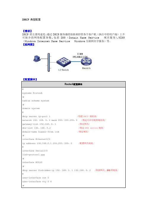
DHCP 典型配置【需求】DHCP 的主要用途是:通过DHCP服务器的协助来控管各个客户机(执行中的用户端)上不可缺少的网络配置参数,包括DNS(Domain Name Service 域名服务),WINS (Windows Internet Name Service Windows互联网名字服务)等。
【组网图】RouterA配置脚本#sysname RouterA#radius scheme system#domain system#dhcp server ip-pool 1 /创建DHCP 地址池/network 192。
168。
0。
0 mask 255。
255.255。
0 /指定可以分配的地址段/gateway—list 192.168。
0。
1 /指定网关/dns—list 192。
168。
0.2 /指定DNS server地址/domain—name huawei-3com。
com /指定域名/#interface Ethernet0/0ip address 192.168.0.1 255.255。
255。
0 /配置网关地址/#interface Serial2/0link—protocol ppp#interface NULL0#dhcp server forbidden-ip 192。
168。
0。
1 192.168。
0。
2 /保留网关、DNS的地址/#user—interface con 0user-interface vty 0 4#return【验证】在PC上执行“ipconfig”,该PC已经通过DHCP自动获取IP地址、网关、域名信息。
C:\〉ipconfigWindows IP ConfigurationEthernet adapter 本地连接:Connection-specific DNS Suffix . : IP Address。
. 。
. 。
. . : 192.168.0。
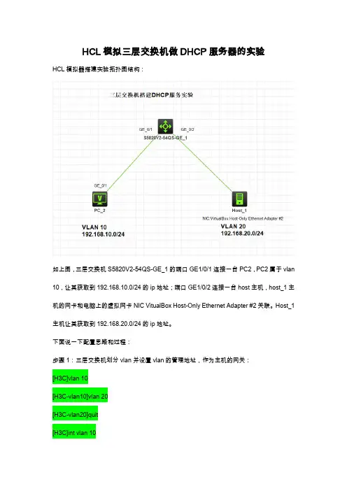
HCL模拟三层交换机做DHCP服务器的实验HCL模拟器搭建实验拓扑图结构:如上图,三层交换机S5820V2-54QS-GE_1的端口GE1/0/1连接一台PC2,PC2属于vlan 10,让其获取到192.168.10.0/24的ip地址;端口GE1/0/2连接一台host主机,host_1主机的网卡和电脑上的虚拟网卡NIC VitualBox Host-Only Ethernet Adapter #2关联。
Host_1主机让其获取到192.168.20.0/24的ip地址。
下面说一下配置思路和过程:步骤1:三层交换机划分vlan并设置vlan的管理地址,作为主机的网关:[H3C]vlan 10[H3C-vlan10]vlan 20[H3C-vlan20]quit[H3C]int vlan 10[H3C-Vlan-interface10]ip address 192.168.10.254 24[H3C-Vlan-interface10]quit[H3C]int vlan 20[H3C-Vlan-interface20]ip address 192.168.20.254 24[H3C-Vlan-interface20]quit步骤2:把相应的端口添加到vlan:[H3C]int g1/0/1[H3C-GigabitEthernet1/0/1]port link-type access[H3C-GigabitEthernet1/0/1]port access vlan 10[H3C-GigabitEthernet1/0/1]quit[H3C]int g1/0/2[H3C-GigabitEthernet1/0/2]port link-type access[H3C-GigabitEthernet1/0/2]port access vlan 20步骤3:设置DHCP地址池:我们可以查看下和dhcp相关的命令:[H3C]dhcp ?class Create a DHCP classclient Configure a DHCP clientdscp Set the Differentiated Services Codepoint (DSCP) value enable Enable DHCPlog Specify DHCP log configurationoption-group Create a DHCP option grouppolicy Configure a DHCP policyrelay Configure a DHCP relay agentserver Configure a DHCP serversmart-relay DHCP smart relaysnooping Configure DHCP snooping其中,dhcp后接server是我们要使用的命令:[H3C]dhcp server ip-pool vlan10pool 设置一个DHCP地址池名为vlan10pool [H3C-dhcp-pool-vlan10pool]network 192.168.10.0 24 设置vlan10pool分配地址段[H3C-dhcp-pool-vlan10pool]gate 按下tab键,自动补全命令[H3C-dhcp-pool-vlan10pool]gateway-list 192.168.10.254 设置地址池网关地址为三层交换机划分的vlan 10的管理ip[H3C-dhcp-pool-vlan10pool]dns[H3C-dhcp-pool-vlan10pool]dns-list 114.114.114.114 设置dns参数[H3C-dhcp-pool-vlan10pool]quit步骤4:设置vlan的DHCP工作模式首先进入到vlan 10,然后设置dhcp工作模式[H3C-Vlan-interface10]dhcp select server[H3C-Vlan-interface10]dhcp server ?apply Apply a DHCP poolcheck Check DHCP packetspolicy-first Policy-first address pool selection[H3C-Vlan-interface10]dhcp server apply ?ip-pool Specify a DHCP pool[H3C-Vlan-interface10]dhcp server apply ip-pool vlan10pool 在这里设置的为vlan10指定的地址池名(ip-pool)不能写错。
三层交换机用作dhcp服务器实验报告实验记录几数据处理一、实验目的与背景随着网络技术的不断发展,三层交换机在现代企业网络中的地位日益重要。
为了提高网络管理的效率和便捷性,本实验旨在通过配置三层交换机作为DHCP服务器,为企业内部计算机自动分配IP地址,从而简化网络配置管理工作。
以下将详细介绍实验过程、数据处理以及实验结果分析。
二、实验环境与工具1.实验设备:三层交换机、多台计算机、网线、交换机console线。
2.实验操作系统:Windows 10、Windows Server 2016。
3.网络配置工具:SecureCRT、Wireshark。
三、实验步骤与数据处理1.配置三层交换机作为DHCP服务器(1)进入交换机配置模式。
(2)创建一个地址池,设置地址范围、默认网关、DHCP服务器选项。
(3)配置端口,设置接口类型、VLAN、IP地址。
2.配置计算机获取DHCP地址(1)连接三层交换机所在的局域网。
(2)启动计算机,观察获取到的IP地址是否符合预期。
3.数据处理(1)记录实验过程中计算机获取到的IP地址。
(2)统计分析IP地址分配情况,验证地址池设置的合理性。
(3)观察并记录网络中计算机的通信情况,评估DHCP服务性能。
四、实验结果与分析1.实验结果经过实验,成功配置了三层交换机作为DHCP服务器,为网络中的计算机自动分配IP地址。
实验过程中,计算机能够顺利获取到分配的IP地址,并实现正常通信。
2.实验分析通过数据处理,发现IP地址分配合理,符合企业内部网络需求。
同时,三层交换机作为DHCP服务器能够有效减轻网络管理负担,提高工作效率。
五、实验总结与建议本次实验验证了三层交换机作为DHCP服务器的可行性,为企业网络管理提供了新的解决方案。
在实际应用中,建议根据网络规模和需求,合理配置地址池,确保IP地址的合理分配。
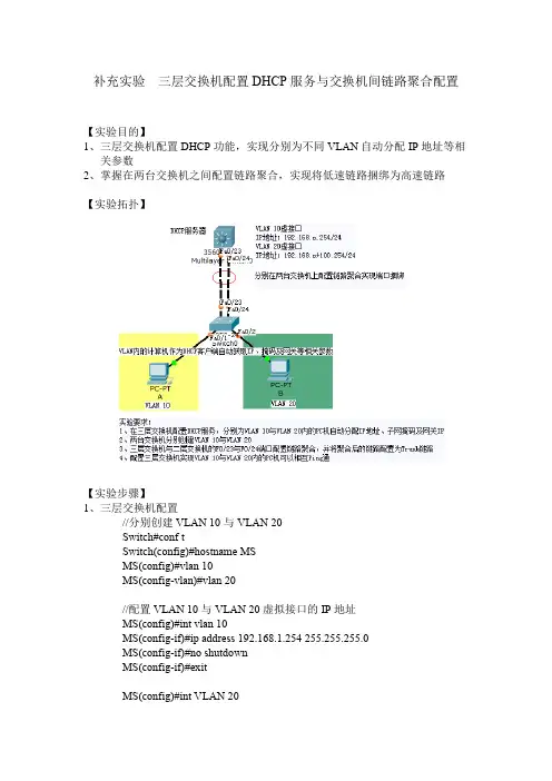
补充实验三层交换机配置DHCP服务与交换机间链路聚合配置【实验目的】1、三层交换机配置DHCP功能,实现分别为不同VLAN自动分配IP地址等相关参数2、掌握在两台交换机之间配置链路聚合,实现将低速链路捆绑为高速链路【实验拓扑】【实验步骤】1、三层交换机配置//分别创建VLAN 10与VLAN 20Switch#conf tSwitch(config)#hostname MSMS(config)#vlan 10MS(config-vlan)#vlan 20//配置VLAN 10与VLAN 20虚拟接口的IP地址MS(config)#int vlan 10MS(config-if)#ip address 192.168.1.254 255.255.255.0MS(config-if)#no shutdownMS(config-if)#exitMS(config)#int VLAN 20MS(config-if)#ip address 192.168.101.254 255.255.255.0MS(config-if)#no shutdownMS(config-if)#exit//三层交换机配置DHCP服务//添加排除地址MS(config)#ip dhcp excluded-address 192.168.1.254MS(config)#ip dhcp excluded-address 192.168.101.254//创建VLAN10与VLAN20两个VLAN自动分配IP地址的地址池及网关IP MS(config)#ip dhcp pool vlan10pool //地址池名称为vlan10poolMS(dhcp-config)#network 192.168.1.0 255.255.255.0//配置VLAN 10虚拟接口IP作为DHCP客户端的网关IPMS(dhcp-config)#default-router 192.168.1.254MS(dhcp-config)#exitMS(config)#ip dhcp pool vlan20pool //地址池名称为vlan10poolMS(dhcp-config)#network 192.168.101.0 255.255.255.0MS(dhcp-config)#default-router 192.168.101.254//配置VLAN20虚拟接口IP作为DHCP客户端的网关IPMS(dhcp-config)#exit//三层交换机的F0/23与F0/24端口捆绑为聚合链路MS(config)#interface range f0/23-24MS(config-if-range)#channel-group 1 mode on //通道组1工作模式为on//在三层交换机上查看聚合端口MS(config-if)#endMS#show interface etherchannel//在三层交换机上查看链路聚合配置MS#show etherchannel summary//三层交换机聚合链路配置为交换机之间VLAN的Trunk链路MS(config)#int port-channel 1 //端口通道1MS(config-if)#switchport trunk encapsulation dot1q//配置Trunk链路封装格式为802.1qMS(config-if)#switchport mode trunk2、二层交换机配置//创建VLAN 10与VLAN 20Switch(config)#vlan 10Switch(config-vlan)#vlan 20Switch(config-vlan)#vlan 20Switch(config-vlan)#exit//划分F0/1端口属于VLAN 10,F0/2端口属于VLAN 20Switch(config)#int f0/1Switch(config-if)#switchport mode accessSwitch(config-if)#switchport access vlan 10Switch(config-if)#exitSwitch(config)#int f0/2Switch(config-if)#switchport mode accessSwitch(config-if)#switchport access vlan 20Switch(config-if)#exitSwitch(config)#//二层交换机的F0/23与F0/24端口捆绑为聚合链路Switch(config)#int range f0/23-24Switch(config-if-range)#channel-group 1 mode on//通道组1工作模式为on //在二层交换机上查看聚合端口Switch#show interface etherchannel//在二层交换机上查看链路聚合配置Switch#show etherchannel summary//二层交换机聚合链路配置为交换机之间VLAN的Trunk链路Switch(config)#int port-channel 1 //端口通道1Switch(config-if)#switchport mode trunk3、两台PC配置为DHCP客户端,实现自动从三层交换机(DHCP服务)获取IP地址、子网掩码及网关IP此时两PC机之间相互无法访问(属于不同VLAN)若要实现不同VLAN的主机间能够相互访问,必须在三层交换机配置路由功能即可。
H3C三层交换机DHCP服务器配置实例H3C三层交换机DHCP服务器配置实例H3C三层交换机作为DHCP服务器,那么其中DHCP服务器要怎么配置呢?下面yjbys店铺为大家分享最新交换机作为DHCP服务器的配置实例,希望对同学们学习DHCP服务器配置有所帮助!DHCP采样UDP链接方式,服务器端口为67,客户机端口为68.实验环境(H3C ENSP)一、配置要点a:在路由器上配置DHCPserver第一步:(系统视图)开启DHCP :DHCP enable第二步:(进入接口视图)为与客户端相连的`端口配置ip地址第三步:(系统视图)建立DHCP地址池 :ip pool aaa第四步:(pool模式下)配置network网段、Gateway-list网关、dns-list DNS服务器地址、excluded-ip-address需要排除的ip 地址第五步:进入接口模式,在接口中启动DHCP动态分配:dhcp select globle第六步:将客户端的dhcp启动即可实例:路由器配置:#sysname Huawei#dhcp enable#ip pool aaagateway-list 192.168.1.1network 192.168.1.0 mask 255.255.255.0excluded-ip-address 192.168.1.10dns-list 192.168.1.10 192.168.10.10#aaaauthentication-scheme defaultauthorization-scheme defaultaccounting-scheme defaultdomain defaultdomain default_adminlocal-user admin password cipher OOCM4m($F4ajUn1vMEIBNUw#local-user admin service-type http#firewall zone Localpriority 16#interface Ethernet0/0/0ip address 192.168.1.1 255.255.255.0dhcp select global#interface Ethernet0/0/1#interface Serial0/0/0link-protocol ppp#interface Serial0/0/1link-protocol ppp#interface Serial0/0/2link-protocol ppp#interface Serial0/0/3link-protocol ppp#interface GigabitEthernet0/0/0#interface GigabitEthernet0/0/1#interface GigabitEthernet0/0/2#interface GigabitEthernet0/0/3#wlan#interface NULL0#user-interface con 0user-interface vty 0 4user-interface vty 16 20#returnb:在三层交换机中为不同vlan配置不同DHCPserver第一步:在三层交换机上建好vlan并分配好端口第二步:(系统视图)开启DHCP :DHCP enable第三步:为每一个vlan都建立一个相应的DHCP地址池(命名可以随意)第四步:为每一个地址池配置好自己相应vlan的network网段、Gateway-list网关、dns-list DNS服务器地址、excluded-ip-address需要排除的ip 地址第五步:进入每一个vlan接口,先配置好各自的ip地址,然后在启动DHCP动态分配:dhcp select globle 第六步:将客户端的dhcp启动即可实例:三层交换机配置:[Huawei]display current-configuration#sysname Huawei#vlan batch 2 to 3#cluster enablentdp enablendp enable#drop illegal-mac alarm#dhcp enable#diffserv domain default#drop-profile default#ip pool aaanetwork 192.168.1.0 mask 255.255.255.0 excluded-ip-address 192.168.1.1dns-list 192.168.10.10#ip pool bbbnetwork 192.168.2.0 mask 255.255.255.0 excluded-ip-address 192.168.2.1dns-list 192.168.10.10#aaaauthentication-scheme default authorization-scheme default accounting-scheme defaultdomain defaultdomain default_adminlocal-user admin password simple admin local-user admin service-type http#interface Vlanif1#interface Vlanif2ip address 192.168.1.1 255.255.255.0 dhcp select global#interface Vlanif3ip address 192.168.2.1 255.255.255.0 dhcp select global#interface MEth0/0/1#interface Ethernet0/0/1port link-type accessport default vlan 2#interface Ethernet0/0/2#interface Ethernet0/0/3interface Ethernet0/0/4 port link-type access port default vlan 3#interface Ethernet0/0/5 #interface Ethernet0/0/6 #interface Ethernet0/0/7 #interface Ethernet0/0/8 #interface Ethernet0/0/9 #interface Ethernet0/0/10 #interface Ethernet0/0/11 #interface Ethernet0/0/12 #interface Ethernet0/0/13 #interface Ethernet0/0/14 #interface Ethernet0/0/15 #interface Ethernet0/0/16 #interface Ethernet0/0/17interface Ethernet0/0/18#interface Ethernet0/0/19#interface Ethernet0/0/20#interface Ethernet0/0/21#interface Ethernet0/0/22#interface GigabitEthernet0/0/1 #interface GigabitEthernet0/0/2 #interface NULL0#user-interface con 0user-interface vty 0 4#return。
一,如果不用交换机的DHCP功能而是利用PC的DHCP功能!1.在交换机上配置DHCP服务器:ip dhcp-server 192.168.0.692.在交换机中为每个VLAN设置同样的DHCP服务器的IP地址:interface Vlan11ip address 192.168.1.254 255.255.255.0ip helper-address 192.168.0.69 DHCP Server IPinterface Vlan12ip address 192.168.2.254 255.255.255.0ip helper-address 192.168.0.69 DHCP Server IP3.在DHCP服务器上设置网络地址分别为192.168.1.0、192.168.2.0的作用域,并将这些作用域的“路由器”选项设置为对应VLAN的接口IP地址。
二利用三层交换机自带的DHCP功能实现多VLAN的IP地址自动分配(一) 配置方法一1.同时为多个VLAN的客户机分配地址2.VLAN内有部分地址采用手工分配的方式3.为客户指定网关、Wins服务器等4.VLAN 2的地址租用有效期限为1天,其它为3天5.按MAC地址为特定用户分配指定的IP地址最终配置如下:ip dhcp excluded-address 10.1.1.1 10.1.1.19 //不用于动态地址分配的地址ip dhcp excluded-address 10.1.1.240 10.1.1.254ip dhcp excluded-address 10.1.2.1 10.1.2.19!ip dhcp pool global //global是pool name,由用户指定network 10.1.0.0 255.255.0.0 //动态分配的地址段domain-name //为客户机配置域后缀dns-server 10.1.1.1 10.1.1.2 //为客户机配置dns服务器netbios-name-server 10.1.1.5 10.1.1.6 //为客户机配置wins服务器netbios-node-type h-node //为客户机配置节点模式(影响名称解释的顺利,如h-node=先通过wins服务器解释...)lease 3 //地址租用期限: 3天ip dhcp pool vlan1network 10.1.1.0 255.255.255.0 //本pool是global的子pool, 将从global pool 继承domain-name等optiondefault-router 10.1.1.100 10.1.1.101 //为客户机配置默认网关!ip dhcp pool vlan2 //为另一VLAN配置的poolnetwork 10.1.2.0 255.255.255.0default-router 10.1.2.100 10.1.2.101lease 1!ip dhcp pool vlan1_john //总是为MAC地址为...的机器分配...地址host 10.1.1.21 255.255.255.0client-identifier 010050.bade.6384 //client-identifier=01加上客户机网卡地址!ip dhcp pool vlan1_tomhost 10.1.1.50 255.255.255.0client-identifier 010010.3ab1.eac8相关的DHCP调试命令:no service dhcp //停止DHCP服务[默认为启用DHCP服务]sh ip dhcp binding //显示地址分配情况show ip dhcp conflict //显示地址冲突情况debug ip dhcp server {events | packets | linkage} //观察DHCP服务器工作情况如果DHCP客户机分配不到IP地址,常见的原因有两个。
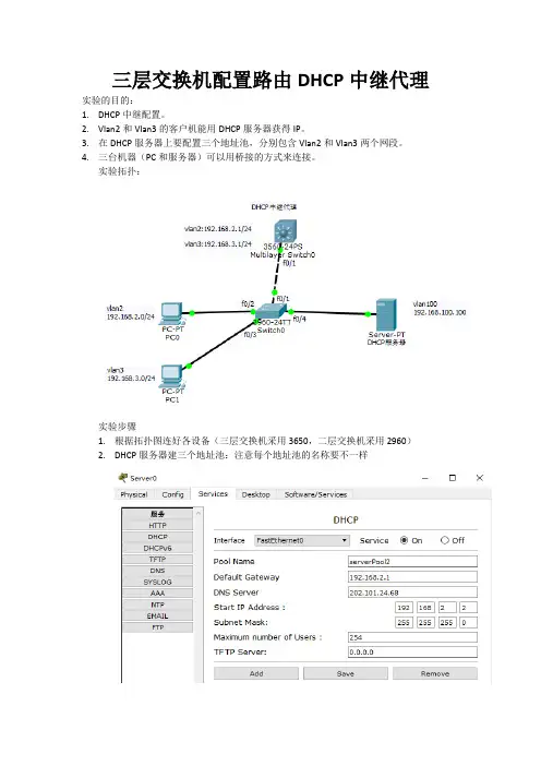
三层交换机配置路由DHCP中继代理实验的目的:1.DHCP中继配置。
2.Vlan2和Vlan3的客户机能用DHCP服务器获得IP。
3.在DHCP服务器上要配置三个地址池,分别包含Vlan2和Vlan3两个网段。
4.三台机器(PC和服务器)可以用桥接的方式来连接。
实验拓扑:实验步骤1.根据拓扑图连好各设备(三层交换机采用3650,二层交换机采用2960)2.DHCP服务器建三个地址池:注意每个地址池的名称要不一样配置DHCP服务器的IP为静态:网关为:(简单就不截图,略!)3.三层交换机的配置Switch(config)#ip routing//开启三层交换机的路由功能,保证不同vlan通过三层交换机通讯Switch(config)#vlan 2 //命名VLAN2Switch(config-vlan)#vlan 3 //命名VLAN3Switch(config-vlan)#vlan 100 //命名VLAN100Switch(config-vlan)#exitSwitch(config)#int vlan 2Switch(config-if)#ip add //给VLAN2配置IPSwitch(config-if)#ip helper-address //给VLAN2配置DHCP中继Switch(config-if)#int vlan 3Switch(config-if)#ip add //给VLAN3配置IPSwitch(config-if)#ip helper-address //给VLAN3配置DHCP中继Switch(config-if)#int vlan 100Switch(config-if)#ip add //给VLAN100配置IP(VLAN100无需配置中继因为vlan100中无客户机)Switch(config-if)#int f0/1Switch (config-if)#switchport trunk encapsulation dot1q //因是三层交换机必须先配置干道(trunk)封装协议,否则配置不了接口模式Switch (config-if)#switchport mode trunk //配置接口f0/1的模式,为干道(trunk)模式4.二层交换机的配置Switch(config)#vlan 2 //命名VLAN2Switch(config-vlan)#vlan 3 //命名VLAN3Switch(config-vlan)#vlan 100 //命名VLAN100Switch(config-vlan)#exitSwitch(config)#int f0/1Switch(config-if)#switchport mode trunk //因为是二层交换机所以不需要配封装协议,2960默认为Switch(config-if)#int f0/2Switch(config-if)#switchport access vlan 2 //将接口f0/2绑定到vlan 2中Switch(config-if)#switchport mode access //将接口f0/2模式配置为access模式(此模式为直连模式,该模式一般是直接连接PC或者服务器)Switch(config-if)#int f0/3Switch(config-if)#switchport access vlan 3 //将接口f0/3绑定到vlan 3中Switch(config-if)#switchport mode access //将接口f0/3模式配置为access模式(此模式为直连模式,该模式一般是直接连接PC或者服务器)Switch(config-if)#int f0/4Switch(config-if)#switchport access vlan 100 //将接口f0/4绑定到vlan 4中Switch(config-if)#switchport mode access //将接口f0/4模式配置为access模式(此模式为直连模式,该模式一般是直接连接PC或者服务器)5.将两台PC机的IP设置为自动获得如上图,同理设置第二台PC,截图略。
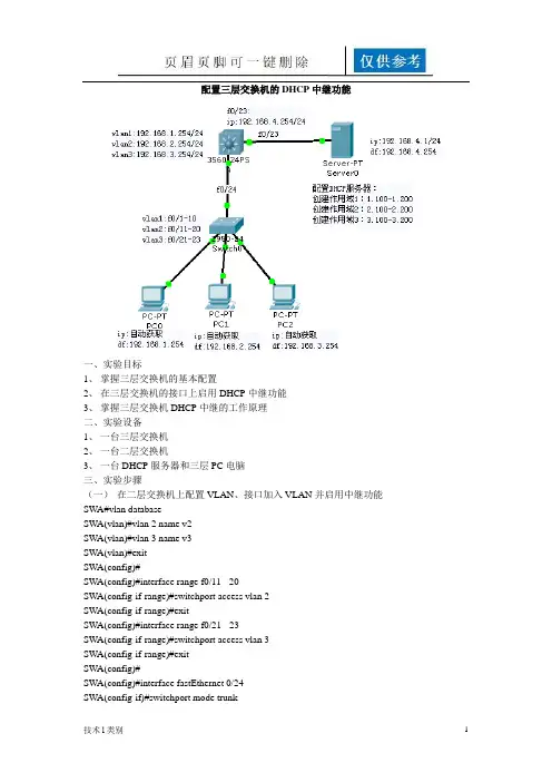
配置三层交换机的DHCP中继功能一、实验目标1、掌握三层交换机的基本配置2、在三层交换机的接口上启用DHCP中继功能3、掌握三层交换机DHCP中继的工作原理二、实验设备1、一台三层交换机2、一台二层交换机3、一台DHCP服务器和三层PC电脑三、实验步骤(一)在二层交换机上配置VLAN、接口加入VLAN并启用中继功能SWA#vlan databaseSWA(vlan)#vlan 2 name v2SWA(vlan)#vlan 3 name v3SWA(vlan)#exitSWA(config)#SWA(config)#interface range f0/11 - 20SWA(config-if-range)#switchport access vlan 2SWA(config-if-range)#exitSWA(config)#interface range f0/21 - 23SWA(config-if-range)#switchport access vlan 3SWA(config-if-range)#exitSWA(config)#SWA(config)#interface fastEthernet 0/24SWA(config-if)#switchport mode trunk(二)在三层交换机上配置VLAN、为VLAN的接口配置IP地址Switch>enableSwitch#configure terminalSwitch(config)#hostname SWBSWB(config)#enable secret 123SWB(config)#exitSWB#vlan databaseSWB(vlan)#vlan 2 name v2SWB(vlan)#vlan 3 name v3SWB(vlan)#exitSWB(config)#interface vlan 1SWB(config-if)#ip address 192.168.1.254 255.255.255.0SWB(config-if)#no shutdownSWB(config-if)#exitSWB(config)#interface vlan 2SWB(config-if)#ip address 192.168.2.254 255.255.255.0SWB(config-if)#no shutdownSWB(config-if)#exitSWB(config)#interface vlan 3SWB(config-if)#ip address 192.168.3.254 255.255.255.0SWB(config-if)#no shutdownSWB(config-if)#endSWB#(三)在三层交换机上启用路由功能、在f0/23接口启用路由功能SWB(config)#interface fastEthernet 0/24SWB(config-if)#switchport mode trunkSWB(config-if)#exitSWB(config)#interface fastEthernet 0/23SWB(config-if)#no switchportSWB(config-if)#ip address 192.168.4.254 255.255.255.0SWB(config-if)#no shutdownSWB(config-if)#endSWB#(四)在三层交换机的SVI接口上启用DHCP中继功能SWB(config)#interface vlan 1SWB(config-if)#ip helper-address 192.168.4.1SWB(config)#interface vlan 2SWB(config-if)#ip helper-address 192.168.4.1SWB(config)#interface vlan 3SWB(config-if)#ip helper-address 192.168.4.1(五)配置DHCP服务器四、实验总结五、实验思考。
实验五DHCP协议的配置
一、DHCP协议的配置
实验目的:掌握DHCP协议的工作原理和工作过程,学会在三层交换机上配置DHCP服务和客户端配置。
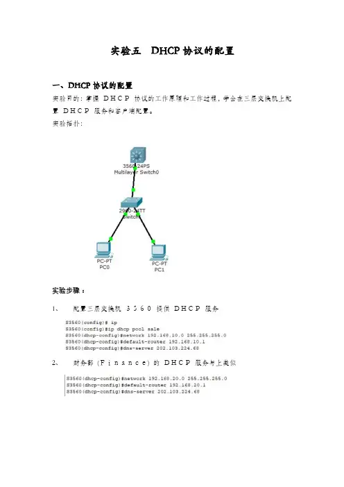
实验拓扑:
实验步骤:
1、配置三层交换机3560提供DHCP服务
2、财务部(Finance) 的DHCP服务与上类似
3、在三层3560交换机上配置两个虚拟网(vlan10和vlan20)
为两个虚拟Vlan接口配置IP地址
4、在2960交换机创建两个vlan并将两个部门的PC机划分到相应的
Vlan端口中
5、配置3560交换机和2960交换机的级联端口Trunk模式
6、设置客户端自动获取地址
7、实验测试: 在客户端测试,在“命名提示符”下,执行“ipconfig”查看
IP地址属性,使用“ping”测试两台PC的连通性
8、使用showipdhcpbinding来查看DHCP的地址绑定情
况
二、DHCP中继的配置
实验目的:使用三层交换+DHCP中继代理技术解决多个VLAN共享同一DHCP服务器问题。
实验拓扑:
9、配置三层交换机的VLAN、Trunk等基本配置
10、配置三层交换机的VLAN虚拟接IP地址
11、配置三层交换机的VLAN中继服务
SwitchA(config-if)#ip helper-address 192.168.0.100 12、启用三层交换机本机路由
13、配置DHCP服务器
14、验证测试
a) 在三层交换机上使用showipdhcpbinding查看在PC上自动获取IP地址的情况
b)两PC能够相互ping通。
实验1:三层交换机配置和DHCP中继
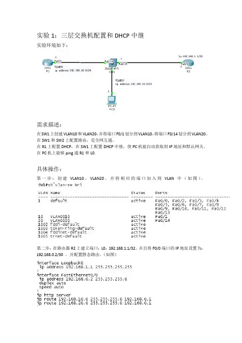
实验环境如下:
需求描述:
在SW1上创建VLAN10和VLAN20,并将端口F0/1划分到VLAN10,将端口F0/14划分到VLAN20。
在SW1和SW2上配置路由,是全网互通。
在R1上配置DHCP,在SW1上配置DHCP中继,使PC机能自动获取到IP地址和默认网关。
在PC机上能够ping通R1和L0.
具体操作:
第一步:创建VLAN10,VLAN20。
并将相应的端口加入到VLAN中(如图)。
第二步:在路由器R2上建立端口:L0:192.168.1.1/32。
并且将F0/0端口的IP地址设置为:192.168.0.2/30 ,并配置静态路由。
(如图)
第三步:将SW1上的VLAN10与VLAN20配上相应的IP(pc与R1的网关地址),如:VLAN10 IP:192.168.10.254/24,VLAN20 IP:192.168.20.254/24.还有F0/15的IP:192.168.0.1/30。
然后再配置一条默认路由指向R2,并在SW1上开启路由功能。
最后在VLAN10的接口模式下键入:IP help-address 192.168.20.1 (如图)
第四部:将R1上的F0/0接口配置IP地址:192.168.20.1/24.并创建DHCP地址池:192.168.10.0/24并配置相关参数。
最后写一条默认路由指向SW1。
(如图)
第五步:验证PC是否得到相应的IP地址并进行全网PING通。
到此本实验全部完成!!!。
51CTO首页我的博客搜索社区:论坛博客下载读书更多登录注册首页|微软活动|Cisco |Security |VoIP |Office |Windows Server |Windows 7|IT职业生涯51cto 51cto博客之星博客之星 用户名:hackerjx 文章数:61 评论数:489 访问量:232011 无忧币:2031 博客积分:3371 博客等级:7注册日期:2008-05-18[Win 7]原来的桌面属性那.. 追梦五年-我和51CTO的那些事 Windows 7 中的“亮.. Windows XP Mode,发布应.. Office 2010 Beta 简体中.. 802.1X认证+DHCP+ACS Ser.. 配置在一台三层交换上,.. 揭秘Cisco NBAR封杀BT和.. 解密Windows 7中的XP Mode 企业网络中部署Cisco ACS.. 配置多台三层交换VLAN间.. [Win 7]安装Windows 7好.. 大中型企业中部署应用AAA.. Cisco SSL VPN 配置详解 配置Cisco IOS EASY VPN ..ISCW实验3:配置Cisco PP.. Cisco IP Communicator .. 使用SDM配置Cisco Easy VPN博客博客统计统计统计信息信息热门热门文章文章hackerjx 的BLOG写留言邀请进圈子发消息加友情链接进家园 加好友MSN/QQ 论坛 开心 人人 豆瓣 新浪微博 分享到:博主的更多文章>>标签:DHCP 多层交换配置 Cisco原创作品,允许转载,转载时请务必以超链接形式标明文章 原始出处 、作者信息和本声明。
否则将追究法律责任。
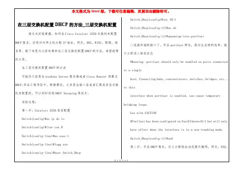
/383839/215400通过本实验实验掌握掌握掌握,,如何在如何在Cisco Catalyst Cisco Catalyst Cisco Catalyst 3550 3550 3550交交换机来配置配置DHCP DHCP DHCP服服务,实现对实现对内内网主机分配IP IP地址地址地址,,网关,DNS DNS,,WINS WINS,,租期租期,,域名等域名等。
华为三层交换机(5328)DHCP中继应用配置实例之前有人提出华为交换机关于DHCP中继配置方面的问题,我做了一个简单的测试,将测试结果分享给大家。
测试拓扑结构:sys #进入系统视图sysname dhcptest #设备重命名dhcp enable #启用DHCP功能Vlan 2 #创建vlan 2port GigabitEthernet 0/0/1 to 0/0/10 #批量添加端口quit #退出接口视图Vlan 5 #创建vlan 5port GigabitEthernet 0/0/11 to 0/0/20 #批量添加端口quit #退出接接口视图interface vlanif 2 #进入VLANIF 接口视图ip address 192.168.1.1 24 #增加VLANIF 接口的IP地址dhcp select relay #通过中继分配IP地址quit #退出接接口视图interface vlanif 5 #进入VLANIF 接口视图ip address 192.168.5.1 24 #配置VLANIF 接口的IP地址ip relay address 192.168.1.5 #增加VLANIF 接口的IP 中继地址dhcp select relay #通过中继分配IP地址quit #退出接口视图System-view #进入系统视图ip relay address 192.168.1.5 vlan 2 #配置DHCP服务器地址和所属vlan---结束检查配置结果查看DHCP 中继的相关统计信息display dhcp relay statistics查看接口的DHCP 中继地址配置display dhcp relay address vlan vlan-id通过以上正确配置后,将测试笔记本插入相应的vlan内,即可获得正确网段地址。
三层交换及DHCP技术配置详解-电脑资料一:实验背景:国立集团是北京一个从事科研开发的企业,公司有4个部门,每个部门大约20人,所以划分了4个VLAN来为4个部门服务,VLAN 之间的通信用3层交换机来实现,而且在外地还有一个办事处,为了和办事处的网络能够互联,公司的3层交换机连接了一个路由器,为了节省成本,路由器上担当了DHCP服务器的功能,来为公司内部的主机分配IP.二:实验目的:1、 VLAN之间的通信通过3层交换机来实现2、路由器为4个VLAN来分配IP地址3、 PC1和PC2分别属于2个部门,能够得到IP地址4、 PC1和PC2之间可以ping通,。
实验拓扑:实验思路:1首先先利用三层交换机的路由功能来实现内网络的通讯(VTP的配置可有可无)2 然后实现内部网络能与路由相通(这里利用的RIP协议)3 在路由器上担当DHCP服务器的功能4 在三层交换机上做DHCP中继5 测试能否分配到IP实验配置:1 首先把交换机之间相连的线路改为trunk然后在SW3创建VTP 添加VLAN 信息SW1(config)#interface f0/1SW1(config-if)#switchport mode trunkSW1(config-if)#no shutdownSW2(config)#interface f0/2SW2(config-if)#switchport mode trunkSW2(config-if)#no shutdownSW3(config)#interface range f0/1 - 2SW3(config-if-range)#switchport mode trunkSW3(config-if-range)#no shutdownSW3#vlan databaseSW3(vlan)#vtp domain t33(创建VTP的域名)SW3(vlan)#vlan 10(添加VLAN 信息)SW3(vlan)#vlan 20查看其他交换机都学到了VLAN 信息,现在把相应的接口加入相应的VLANSW1(config)#interface f0/0SW1(config-if)#switchport access vlan 10SW2(config)#interface f0/0SW2(config-if)#switchport access vlan 202:PC1 属于VLAN 10 分配的IP地址为192.168.10.0/24 (IP192.168.10.100)PC2 属于VLAN 20 分配的IP地址为192.168.20.0/24 (IP为192.168.20.100)由于三层交换式利用VLAN 进行转发数据的,所以必须给每个VLAN配置IP,每个VLAN配置的IP相当于PC机的默认网关,必须和相同的VLAN在同一网段SW3(config)#ip routing(开启路由功能)SW3(config)#interface vlan 10SW3(config-if)#ip address 192.168.10.1 255.255.255.0SW3(config)#interface vlan 20SW3(config-if)#ip address 192.168.20.1 255.255.255.0测试:完成以上配置后,把PC得网关指向给VLAN配置的 IP用PC1 ping PC2Pinging 192.168.20.100 with 32 bytes of data:Reply from 192.168.20.100: bytes=32 time<1ms TTL=64Reply from 192.168.20.100: bytes=32 time<1ms TTL=64Reply from 192.168.20.100: bytes=32 time<1ms TTL=64Reply from 192.168.20.100: bytes=32 time<1ms TTL=64Ping statistics for 192.168.20.100:Packets: Sent = 4, Received = 4, Lost = 0 (0% loss)三层交换已经实现了不同VLAN 之间的通讯,内部网络已经通了3 :下面配置路由,实现内部网络到路由的全部互通SW3(config)#interface f0/0SW3(config-if)#no switchport (在三层交换上开启路由接口)SW3(config-if)#ip address 192.168.30.1 255.255.255.0R1(config)#interface f0/0R1(config-if)#ip address 192.168.30.2 255.255.255.0R1(config-if)#no shutdownSW3(config)#router rip (RIP宣告)SW3(config-router)#network 192.168.10.0SW3(config-router)#network 192.168.20.0SW3(config-router)#network 192.168.30.0R1(config)#router rip (RIP宣告)R1(config-router)#network 192.168.30.0查看路由表R1#show ip routeCodes: C - connected, S - static, R - RIP, M - mobile, B - BGPD - EIGRP, EX - EIGRP external, O - OSPF, IA - OSPF inter areaN1 - OSPF NSSA external type 1, N2 - OSPF NSSA external type 2E1 - OSPF external type 1, E2 - OSPF external type 2i - IS-IS, su - IS-IS summary, L1 - IS-IS level-1, L2 - IS-IS level-2ia - IS-IS inter area, * - candidate default, U - per-user static routeo - ODR, P - periodic downloaded static routeGateway of last resort is not setC 192.168.30.0/24 is directly connected, FastEthernet0/0R 192.168.10.0/24 [120/1] via 192.168.30.1, 00:00:06, FastEthernet0/0R 192.168.20.0/24 [120/1] via 192.168.30.1, 00:00:06, FastEthernet0/0说明:路由器已经学到的路由表,测试网路连通性(用PC机ping 路由器可以通),在这里做这一步是因为要想让R1担当DHCP服务器,首先通讯时前提的保障,每做一步都验证一步,可以让我们很好的发现错误在R1上配置DHCP服务器R1(config)#ip dhcp pool vlan10(分配给那个VLAN)R1(dhcp-config)#network 192.168.10.0 255.255.255.0(分配给VLAN的网段)R1(dhcp-config)#default-router 192.168.10.1 (分配的网关,注意一定要指向三层交换VLAN的IP)R1(dhcp-config)#dns-server 1.1.1.1(DNS服务器的IP,这里可以没有)R1(dhcp-config)#lease 10(租用的期限)R1(config)#ip dhcp pool vlan20(分配给那个VLAN)R1(dhcp-config)#network 192.168.20.0 255.255.255.0(分配给VLAN的网段)R1(dhcp-config)#default-router 192.168.20.1 (分配的网关,注意一定要指向三层交换VLAN的IP)R1(dhcp-config)#dns-server 1.1.1.1(DNS服务器的IP,这里可以没有)R1(dhcp-config)#lease 10(租用的期限)R1(config)#ip dhcp excluded-address 192.168.10.1 192.168.10.50(排除不分配的IP)R1(config)#ip dhcp excluded-address 192.168.20.1 192.168.20.100(排除不分配的IP)可以更好的看出效果4:在三层交换机上做DHCP中继,应为DHCP的获取的方式为广播,由于广播不能再不同的VLAN之间进行广播下载文档润稿写作咨询。
switch1:Switch(config)#int port-channel 1Switch(config-if)#no switchportSwitch(config-if)#ip add 172.16.12.2 255.255.255.0Switch(config)#int range f0/1-2Switch(config-if-range)#channel-protocol pagpSwitch(config-if-range)#no switchportSwitch(config-if-range)#channel group 1 mode on注意:三层Ethernet channel配置完成后,ping两台路由器,测试连通性Switch(config)#int f0/3Switch(config)#no switchportSwitch(config-if)#ip helper-address 192.168.1.254switch0:Switch(config)#int port-channel 1Switch(config-if)#no switchportSwitch(config-if)#ip add 172.16.12.1 255.255.255.0Switch(config)#int range f0/1-2Switch(config-if-range)#channel-protocol pagpSwitch(config-if-range)#no switchportSwitch(config-if-range)#channel group 1 mode onSWitch(config)#ip dhcp pool ccnaSwitch(config-dhcp)#network 192.168.1.0 255.255.255.0Switch(config-dhcp)#default-router 192.168.1.254Switch(config-dhcp)#ip dhcp excluded-add 192.168.1.254注意:(1)当Windows 客户端无法从DHCP 服务器租约到IP 地址时,计算机会自动产生一个169.254.0.0/16 的IP地址。
1Router(config)#host sw1 sw1(config)#end*Mar 1 00:09:20.039: %SYS-5-CONFIG_I: Configured from console by consolen添加vlan10和vlan20 sw1#vlan data sw1(vlan)#vlan 10 VLAN 10 modified: sw1(vlan)#vlan 20 VLAN 20 modified: sw1(vlan)#exit APPL Y completed. Exiting....sw1#sh vlan-sVLAN Name Status Ports ---- -------------------------------- --------- ------------------------------- 1 default active110201003 tr 101003 1500 1005 0 - - srb 1 10021004 fdnet 101004 1500 - - 1 ibm - 0 01005 trnet 101005 1500 - - 1 ibm - 0 0sw1#封装trunk链路sw1#conf t*Marsw1(config)#sw1# conf tEnter configuration commands, one per line. End with CNTL/Z.sw1(config)#int f0/0sw1(config-if)#sw mo accsw1(config-if)#sw acc vlan 10sw1(config-if)#int f0/1sw1(config-if)#sw mo accsw1(config-if)#sw acc vlan 20sw1(config-if)#exitsw1(config)#2.配置三层交换机sw2Switch>enSwitch#conf tEnter configuration commands, one per line. End with CNTL/Z. Switch(config)#vlan 103Switch(config-vlan)#exitSwitch(config-vlan)#vlan 20Switch(config-vlan)#exitSwitch(config)#^ZSwitch#Switch#sh vlanVLAN Name1 defaultSwitch(config-if)#end开启路由功能,配置SVI端口,在vlan上部署ip地址Switch(config)#int vlan 10Switch(config-if)#ip add 192.168.10.1 255.255.255.0Switch(config-if)#no shSwitch(config-if)#exitSwitch(config)#int vlan 20Switch(config-if)#ip add 192.168.20.1 255.255.255.0Switch(config-if)#exitSwitch(config)#^ZSwitch#sh ip rout00:09:54: %SYS-5-CONFIG_I: Configured from console by consoleip rouSwitch(config-if)#no shSwitch(config-if)#endSwitch#sw2#sh ip routeCodes: C - connected, S - static, R - RIP, M - mobile, B - BGPD - EIGRP, EX - EIGRP external, O - OSPF, IA - OSPF inter areaN1 - OSPF NSSA external type 1, N2 - OSPF NSSA external type 2E1 - OSPF external type 1, E2 - OSPF external type 2i - IS-IS, su - IS-IS summary, L1 - IS-IS level-1, L2 - IS-IS level-2ia - IS-IS inter area, * - candidate default, U - per-user static routeo - ODR, P - periodic downloaded static routeGateway of last resort is not setC 192.168.10.0/24 is directly connected, Vlan10C 192.168.20.0/24 is directly connected, Vlan2010.0.0.0/24 is subnetted, 1 subnets5C 10.1.1.0 is directly connected, FastEthernet0/11sw2#3.配置R1R2测试路由器Router>Router>enRouter#conf tr1(config)#int e0/0r1(config-if)#no shr1(config-if)#endr1#*Mar 1 00:15:55.551: %SYS-5-CONFIG_I: Configured from console by consoleping*Mar 1 00:15:56.711: %LINK-3-UPDOWN: Interface Ethernet0/0, changed state to up*Marr1#ping 192.168.10.1Type escape sequence to abort.r2(config-if)#ip add 192.168.20.2 255.255.255.0r2(config-if)#no shr2(config-if)#end测试直连邻居r2#ping 192.168.20.1Type escape sequence to abort.Sending 5, 100-byte ICMP Echos to 192.168.20.1, timeout is 2 seconds: .!!!!Success rate is 80 percent (4/5), round-trip min/avg/max = 72/84/96 ms r2#Type escape sequence to abort.Sending 5, 100-byte ICMP Echos to 10.1.1.1, timeout is 2 seconds:.!!!!Success rate is 80 percent (4/5), round-trip min/avg/max = 68/71/72 ms5.部署动态路由协议三层交换机上配置Switch(config)#router eigrp 10Switch(config-router)#net 192.168.10.0Switch(config-router)#net 192.168.20.0Switch(config-router)#net 10.0.0.0Switch(config-router)#end路由器上配置7Router#conf tEnter configuration commands, one per line. End with CNTL/Z. Router(config)#host r3r3(config)#int loop0*Mar 1 00:27:59.703: %LINEPROTO-5-UPDOWN: Line protocol on Interface Loopback0, changed state to upr3(config-if)#ip add 200.1.1.1 255.255.255.0r3(config-if)#exit*Marr3(config-router)#endr3#*Marr3#6.测试路由从R1穿过二层交换机sw1,三层交换机sw2,以及路由器r1#ping 200.1.1.1Type escape sequence to abort.D 200.1.1.0/24 [90/156160] via 10.1.1.2, 00:01:47, FastEthernet0/11 C 192.168.10.0/24 is directly connected, Vlan10C 192.168.20.0/24 is directly connected, Vlan2010.0.0.0/8 is variably subnetted, 2 subnets, 2 masksC 10.1.1.0/24 is directly connected, FastEthernet0/11D 10.0.0.0/8 is a summary, 00:02:58, Null0sw2#r3#sh ip routeCodes: C - connected, S - static, R - RIP, M - mobile, B - BGPD - EIGRP, EX - EIGRP external, O - OSPF, IA - OSPF inter areaN1 - OSPF NSSA external type 1, N2 - OSPF NSSA external type 2E1 - OSPF external type 1, E2 - OSPF external type 2i - IS-IS, su - IS-IS summary, L1 - IS-IS level-1, L2 - IS-IS level-2ia - IS-IS inter area, * - candidate default, U - per-user static routeo - ODR, P - periodic downloaded static routeGateway of last resort is not setC 200.1.1.0/24 is directly connected, Loopback0DCdns-server DNS serversdomain-name Domain nameexit Exit from DHCP pool configuration mode hardware-address Client hardware addresshost Client IP address and masklease Address lease timenetbios-name-servernetbios-node-typenetworknext-servernooptionSwitch(config)#Switch(dhcp-config)#network 192.168.20.0 /24Switch(dhcp-config)#defau 192.168.20.1Switch(dhcp-config)#exitSwitch(config)#ip dhcp exclu 192.168.20.1 192.168.20.10 Switch(config)#Switch#sh ip dhcp ser stMemory usage 5215Address pools 2Database agents 0Automatic bindings 0Manual bindings 0Expired bindings 0Malformed messages 09Message ReceivedBOOTREQUEST 0DHCPDISCOVER 0DHCPREQUEST 0DHCPDECLINEDHCPRELEASEDHCPINFORMMessageBOOTREPL YDHCPOFFERDHCPACKDHCPNAKSwitch#IP address Hardware address Lease expiration…………………….(略)Switch#把路由器R1R2上配置成自动获取地址,查询是否成功。
单台三层交换机Vlan 间通信实验【实验目的】掌握三层交换机划分Vlan 的方法掌握三层交换机中定义地址池的方法掌握三层交换机中设置可分配的子网的方法掌握三层交换机中设置DNS 服务器的方法掌握三层交换机中设置子网网关的方法掌握三层交换中保留不分配地址的方法掌握三层交换机中设置地址租约期的方法掌握配置访问控制列表的方法掌握将访问控制列表应用到VLAN 的方法【实验设备】锐捷S3760E 三层交换机1台Pc 机 4台直通线4条配置线1条【实验拓扑】【实验要求】一台锐捷SE760E 交换机,划分三个vlan :(1)Vlan 2:为服务器所在网络,命名为server,IP 地址段为192.168.2.0,子网掩码:255.255.255.0,网关:192.168.2.1,域服务器为windows 2000 advance server,同时兼作DNS 服务器,IP 地址为192.168.2.10(2)Vlan 3为客户机1所在网络,命名为work01,IP 地址段为192.168.3.0,子网掩码:255.255.255.0,网关:192.168.3.1Vlan 2 IP:192.168.2.1Vlan 3 IP:192.168.3.1Vlan 4 IP:192.168.4.1F0/1 F0/2 F0/9F0/17IP:192.168.2.10(3)Vlan 4为客户机2所在网络,命名为work02,IP地址段为192.168.4.0,子网掩码:255.255.255.0,网关:192.168.4.1,(4)锐捷SE760E交换机作DHCP服务器,端口1-8划到VLAN 2,端口9-16划分到VLAN 3,端口17-24划分到VLAN 4,DHCP服务器实现功能:各VLAN保留2-10的IP地址不分配,例如:192.168.2.0的网段,保留192.168.2.2至192.168.2.10的IP地址段不分配.(5)安全要求:VLAN 3和VLAN 4不允许互相访问,但都可以访问服务器所在的VLAN 2,默认访问控制列表的规则是拒绝所有包。
【实验步骤】第一步:创建VLAN:switch>enable (进入特权模式)switch#vlan database (进入vlan数据库)switch(vlan)#vlan 2 name server (创建vlan 2并命名为server)switch(vlan)#vlan 3 name work01 (创建vlan 3并命名为work01)switch(vlan)#vlan 4 name work02 (创建vlan 4并命名为work02)第二步:设置vlan ip地址:switch#configure terminal (进入全局模式)switch(config)#interface vlan 2 (进入vlan 2)switch(config-vlan)#ip address 192.168.2.1 255.255.255.0 (设置vlan 2的IP地址)switch(config-vlan)#no shutdown (激活IP地址管理)switch(config-vlan)#interface vlan 3 (进入vlan 3)switch(config-vlan)#ip address 192.168.3.1 255.255.255.0 (设置vlan 3的IP地址)switch(config-vlan)#no shutdown (激活IP地址管理)switch(config-vlan)#interface vlan 4 (进入vlan 4)switch(config-vlan)#ip address 192.168.4.1 255.255.255.0 (设置vlan 4的IP地址)switch(config-vlan)#no shutdown (激活IP地址管理)switch(config-vlan)#exit (退回上一级)/* 注意:由于此时没有将端口分配置到vlan 2,3,4,所以各vlan会down掉,待将端口分配到各vlan后,vlan会起来*/第三步:设置所有端口工作模式switch(config)#interface range fastethernet 0/1-24 (进入1-24号端口)switch(config-if-range)#switchport mode access (设置端口模式为access)switch(config-if-range)#spanning-tree portfast (生成树为快速启动模式)switch(config-vlan)#exit (退回上一级)第四步:将端口添加到vlan 2、3、4中/*将端口1-8添加到vlan 2*/switch(config#)interface range fastethernet 0/1-8 (进入1-8号端口)switch(config-if-range)#switchport access vlan 2 (将1-8号端口划给vlan 2)switch(config-if-range)#exit (退回上一级)/*将端口9-16添加到vlan 3*/switch(config)#interface range fastethernet 0/9-16 (进入9-16号端口)switch(config-if-range)#switchport access vlan 3 (将9-16号端口划给vlan 3)switch(config-if-range)#exit (退回上一级)/*将端口17-24添加到vlan 4*/switch(config)#interface range fastethernet 0/17-24 (进入17-24号端口)switch(config-if-range)#switchport access vlan 4 (将17-24号端口划给vlan 4)switch(config-if-range)#exit (退回上一级)/*经过这一步后,各vlan会起来*/第五步:配置锐捷se760e作为dhcp服务器/*vlan 2可用地址池和相应参数的配置,有几个vlan要设几个地址池*/switch(config)#ip dhcp pool test01(设置地址池test01)switch(dhcp-config)#network 192.168.2.0 255.255.255.0 (设置可分配的子网)switch(dhcp-config)#dns-server 192.168.2.10 (设置dns服务器)switch(dhcp-config)#default-router 192.168.2.1 (设置该子网的网关)switch(dhcp-config)#lease infinite (设置dhcp地址租约期为永久)/*配置vlan 3所用的地址池和相应参数*/switch(config)#ip dhcp pool test02(设置地址池test02)switch(dhcp-config)#network 192.168.3.0 255.255.255.0 (设置可分配的子网)switch(dhcp-config)#dns-server 192.168.2.10 (设置dns服务器)switch(dhcp-config)#default-router 192.168.3.1 (设置该子网的网关)switch(dhcp-config)#lease 8 (设置dhcp地址租约期为8天) /*配置vlan 4所用的地址池和相应参数*/switch(config)#ip dhcp pool test03(设置地址池test03)switch(dhcp-config)#network 192.168.4.0 255.255.255.0 (设置可分配的子网)switch(dhcp-config)#dns-server 192.168.2.10 (设置dns服务器)switch(dhcp-config)#default-router 192.168.4.1 (设置该子网的网关)switch(config-if-range)#exit (退回上一级)第六步:设置dhcp保留不分配的地址(每个网段从2号到10都不能分配)switch(config)#ip dhcp excluded-address 192.168.2.2 192.168.2.10switch(config)#ip dhcp excluded-address 192.168.3.2 192.168.3.10switch(config)#ip dhcp excluded-address 192.168.4.2 192.168.4.10第七步:启用路由/*路由启用后,各vlan间主机可互相访问*/switch(config)#ip routing测试:设每一台主机IP地址为动态获取,然后用IPconfig得到当前地址,相互ping看是否能通,结果应该都能通。
第八步:配置访问控制列表 denyswitch(config)access-list 103 permit ip 192.168.2.0 0.0.0.255 192.168.3.0 0.0.0.255 switch(config)access-list 103 permit ip 192.168.3.0 0.0.0.255 192.168.2.0 0.0.0.255 switch(config)access-list 103 permit udp any any eq bootpcswitch(config)access-list 103 permit udp any any eq tftpswitch(config)access-list 103 permit udp any eq bootpc anyswitch(config)access-list 103 permit udp any eq tftp anyswitch(config)access-list 104 permit ip 192.168.2.0 0.0.0.255 192.168.4.0 0.0.0.255 switch(config)access-list 104 permit ip 192.168.4.0 0.0.0.255 192.168.2.0 0.0.0.255 switch(config)access-list 104 permit udp any eq tftp anyswitch(config)access-list 104 permit udp any eq bootpc anyswitch(config)access-list 104 permit udp any eq bootpc anyswitch(config)access-list 104 permit udp any eq tftp any第九步:应用访问控制列表/*将访问控制列表应用到vlan 3和vlan 4,vlan 2不需要*/switch(config)#int vlan 3switch(config-vlan)#ip access-group 103 outswitch(config-vlan)#exit (退回上一级)switch(config)#int vlan 4switch(config-vlan)#ip access-group 104 out第十步:结束并保存配置switch(config-vlan)#end (退回到特权模式)switch#copy running-config startup-config (保存当前配置)测试结果:测试:设每一台主机IP地址为动态获取,然后用IPconfig得到当前地址,相互ping看是否能通*结果应该是2和3能通,2和4能通,3和4不能通。