汽车检具制作标准
- 格式:pdf
- 大小:1.78 MB
- 文档页数:94
钣金件检具制作范xx公司检具概论检具是冲压件和焊接件等在线检测检验夹具的简称,与其它文件中提到的样架具有相同意义。
检具是一种按需方特定要求专门制造的检测工具。
检具的形面必须根据零件的CAD数据铣削加工,能体现零件的所有参数,对零件进行定性检测。
对于零件上的某些极重要的功能性尺寸,还能利用检具进行数值检测。
检具还应具有测量支架的功能,但是当检具在线检测功能与测量支架功能不能同时满足时,应首先满足检具的在线检测功能。
检具的设计、制造和验收应以产品图纸和主模型(或CAD数据)为基准。
当零件无主模型(或CAD数据)时,应以产品图纸和经需方认可的样件作为依据。
在正常使用频率和良好的保养维护情况下,应保证检具与其对应的压延模具和焊接夹具有相同的使用寿命。
检查治具式样决定时考虑事项:A.成品要求精度的部位及精度确认方法。
B.精度要求的重要度及确认方法。
C.成品在冲压加工时产生变形量考虑。
D.使用上之考虑(方便、轻量化)。
E.整体结构坚实不变形。
目次检具概述一.单件检具式样说明 (1)1. 检查治具基本式样 (2)1.1基本式样 (2)1.2使用目的 (2)1.3使用材料 (2)1.3.1轮廓表面 (2)1.3.2检具骨架 (2)1.3.3基准块 (3)2. 制作式样说明 (3)2.1检查治具制作方向 (3)2.2剪线及成品末端式样 (4)2.3折线 (4)2.4一般孔 (4)2.5翻边孔 (4)2.6钣件定位 (6)2.6.1基准孔 (7)2.6.2零贴面 (10)2.6.3支撑与夹持 (11)3. 检具制作基本要求 (11)3.1形状面要求 (12)3.1.1检查面 (12)3.1.2非检查面 (12)3.1.3零接触面 (13)3.2分割体 (14)3.2.2钣件检查需要 (14)3.3端面样板 (15)3.4钣件固定 (15)3.5治具搬运 (16)3.5.1吊取装置 (16)3.5.2搬运孔 (17)4. 途装 (18)4.1检查作业性质之区分 (18)4.2外观途装 (18)4.3车种区别 (18)4.4途装色号 (19)5.基准 (19)5.1基准线 (19)5.2基准面 (20)5.3基准指示 (21)5.4其它 (21)二.车体组合件量具(U G)制作说明 (22)1. UG之定义 (22)2. UG之功能 (22)3.UG之主要结构 (22)3.1底座 (22)3.2.1定位用支架 (22)3.2.1检验用支架 (22)4. UG设计所需标准之质料 (23)5. 设计与制图之程序 (24)5.1制图程序 (24)5.2制图规定 (25)5.3设计及制图要点 (25)一、单件检具式样说明1.检查治具基本式样:1.1.基本式样:零件形状、剪线、折线、孔位之检查。
上海通用汽车有限公司(SGM)检具标准(SGM)1996年,来自GM卡车集团、中等/豪华及小型汽车集团的代表成立了一个开发小组,对GM的生产件供应商检具标准进行了重新编制。
GM给生产件供应商的检具标准是为了建立GM供应商PPAP检具全球性的公用标准而开发的。
另外,在开发过程中,还得到了Saturn、GM动力总成和GM加拿大集团的合作。
SGM的检具标准是依据GM生产件供应商的检具标准,另外通过近几年对国内生产件供应商检具认证过程中,所积累的经验,同时结合国内的具体情况,对原来的GM生产件供应商检具标准进行了补充,为国内生产件供应商的PPAP所要求的检具认证制定了标准。
更改信息 3I. 序言 4 II. 零件供应商的责任 5 III. 设计概念 6IV. 概念批准 7 V. 设计要求 7 VI. 制造要求 10 VII. 认证要求 12 VIII. 检具重复性和再现性的要求 13 IX. 检具最终批准15X. 保养要求 15 XI. 术语 15 XII. 附录A 17 XIII. 附录B 18 XIV. 附录C19版本日期段落条目1.0 12/1997 发布2.0 08/2002 发布3.0 03/2005 发布本标准中如发生任何更改都将记录在本页中。
当发生新的更改时,在保留本页清单原有记录的基础上,再增加新的更改内容。
修订后的版本将以版本1.0、2.0、3.0的顺序发布。
当不同的版本发布时,通过参照段落和条目的相应内容,可迅速找出更改内容。
本文件替代下列文件:卡车和客车检具/量具标准(T& B 391)、12月、1989。
,, 中等/豪华汽车集团检具设计/制造标准,4月,1996。
I.A.依照上海通用汽车有限公司(SGM),先期产品质量策划手册(APQP)和生产件批准程序(PPAP)的要求,每当需要时,零件供应商应按照他们的质量计划获取检具来检验他们的产品。
生产件供应商在对SGM的零件的检具进行报价、设计和制造时,除了使用他们自己的标准和要求外,还要参照本手册。

汽车零部件检具制作要求—范文1. 检具制作依据1.1按附件1 所涉及的冲压件开发检具要求制作检具;1.2检具设计、制造依据甲方提供的冲压件单品检具方案、产品3D 数模及产品图纸。
2. 检具技术要求2.1 检具的设计要求:2.1.1 乙方应依据甲方提供的产品3D 数模及产品图纸设计检具。
设计完成后,由甲方进行评审及会签。
会签前三天乙方将检具图的电子文件传给甲方,甲方在三天内把审核意见反馈给乙方;乙方根据甲方反馈意见及时更改图纸,然后带图纸到甲方进行会签。
检具图纸2D 采用CAD, 3D 采用CATIA或UG;2.1.2 检具设计图纸必须符合国家机械制图标准,图形、标识、文字只能有一个解释,使人容易了解和掌握;图面整洁、文字清晰、标注完整;2.1.3 检具所有装配件都应单独绘制零件图,并且所有装配件(包括底座、起吊棒、搬运把手等辅助件)其装配关系都应在装配图上表示清楚,必要时可用剖面图表示;2.1.4 检具图上应明确基准孔,基准面、定位面,夹紧点、检测点等;2.1.5 检具检测部位的间隙值、高差值、对应检测销符号,用激光刻字的形式在检具上标明;2.1.6 检具设计制造应充分考虑方便检测人员进行检查,冲压件上下检具应方便无干涉;2.1.7 被检测零件放置于检具上的位置原则上必须和其在车身坐标系中的位置一致。
如果考虑到便于操作等人体工程原理和节约费用等因素,特殊情况下允许将零件旋转±90°或±180°。
但必须经过甲方同意方可执行;2.1.8 零件一般情况下通过2 个定位孔,借助可插入式定位销的插入或螺栓式定位销旋紧而固定于检具上, 检具定位面, 支撑面及夹头通常根据产品结构特点进行布置和安装, 定位(孔)面、支承面均采用装配式结构。
夹头必须按顺序进行数字编码。
如果零件不以孔而改为面作为定位,定位面的尺寸规格在产品图纸上有明确的规定;2.1.9 对于左右对称,并且通过同一模具同时成型的零件,其检具通常采用型体和骨架部分分开,共享底座的结构形式;2.1.10 检测样板根据零件的检测要求,可采用固定式、可拆卸式、旋转式等结构;2.1.11当产品更改时,检具图(包括3D、2D)必须及时、准确按技术通知单进行更改,做到数模、图纸和实物相一致;2.1.12检具底板必须刻注车身坐标线X向、Y向及Z向,坐标方向的确定依据此制件位于整车上的坐标方向。
修订履历说明:关于流程类文件及标准化要求,有“受控文件”印章的文本才可以作为工作之用途。
文件名称汽车产品检具标准文件类型三级文件页码7/125.4.3初验收合格后有须外协表面处理的部件需及时准备好以便外协。
5.5组装5.5.1试装所有零件时均按轻取轻放的原则,认真把每个部位擦试干净,不能有一粒杂物,以确保试装精度。
5.5.2试装时所有螺丝均不能拧得太紧,以防调试过程中有滑丝现象。
5.5.3试装时认真核对图纸,检查是否有漏装、错装现象发生。
5.6自检5.6.1检具试装好后要结合3D图、2D图认真检查每一个零件是否符合设计制作要求(包括标识以及是否有加工、设计缺陷),作好自检报告。
5.6.2如有发现不合要求的情况要及时通知相关人员及时处理、解决。
6.检测精度要求6.1、检具整体装配精度(对应检具底座的基面/基准孔)单位:mm底板平行度:0.1/1000基准面平行度、垂直度:0.05/1000基准孔位置:±0.05基准孔之间的相对位置误差:±0.03定位孔位置:±0.05检验销孔位置:±0.05支撑面:±0.1功能检测面:±0.1栅格线位置相对基准的误差:0.1/10006.2、检具加工基准-标牌-起重-定位销技术标准-编号要求:6.2.1底座上检具测量基准孔孔径及位置要求6.2.1.1测量基准孔数量为3,在检具上总体位置见图示1。
(图示1)6.2.1.2大型检具测量基准孔孔径及具体位置要求见图示2。
文件名称汽车产品检具标准文件类型三级文件页码8/12(图示2)6.2.1.3小型检具(底座采用铝板)测量基准孔孔径及具体位置要求见图示3。
(图示3)6.2.1.4测量基准孔上保护盖尺寸见图示4,保护盖安装时要求中心与孔中心对正,三个保护盖安装后要求坐标方向一致见图示5。
(图示4)文件名称汽车产品检具标准文件类型三级文件页码9/12(图示5)6.2.2关于检具标牌的要求6.2.2.1检具标牌在检具上的安装位置见图示1。

钣金件检具制作范xx公司检具概论检具是冲压件和焊接件等在线检测检验夹具的简称,与其它文件中提到的样架具有相同意义。
检具是一种按需方特定要求专门制造的检测工具。
检具的形面必须根据零件的CAD数据铣削加工,能体现零件的所有参数,对零件进行定性检测。
对于零件上的某些极重要的功能性尺寸,还能利用检具进行数值检测。
检具还应具有测量支架的功能,但是当检具在线检测功能与测量支架功能不能同时满足时,应首先满足检具的在线检测功能。
检具的设计、制造和验收应以产品图纸和主模型(或CAD数据)为基准。
当零件无主模型(或CAD数据)时,应以产品图纸和经需方认可的样件作为依据。
在正常使用频率和良好的保养维护情况下,应保证检具与其对应的压延模具和焊接夹具有相同的使用寿命。
检查治具式样决定时考虑事项:A.成品要求精度的部位及精度确认方法。
B.精度要求的重要度及确认方法。
C.成品在冲压加工时产生变形量考虑。
D.使用上之考虑(方便、轻量化)。
E.整体结构坚实不变形。
目次检具概述一.单件检具式样说明 (1)1. 检查治具基本式样 (2)1.1基本式样 (2)1.2使用目的 (2)1.3使用材料 (2)1.3.1轮廓表面 (2)1.3.2检具骨架 (2)1.3.3基准块 (3)2. 制作式样说明 (3)2.1检查治具制作方向 (3)2.2剪线及成品末端式样 (4)2.3折线 (4)2.4一般孔 (4)2.5翻边孔 (4)2.6钣件定位 (6)2.6.1基准孔 (7)2.6.2零贴面 (10)2.6.3支撑与夹持 (11)3. 检具制作基本要求 (11)3.1形状面要求 (12)3.1.1检查面 (12)3.1.2非检查面 (12)3.1.3零接触面 (13)3.2分割体 (14)3.2.2钣件检查需要 (14)3.3端面样板 (15)3.4钣件固定 (15)3.5治具搬运 (16)3.5.1吊取装置 (16)3.5.2搬运孔 (17)4. 途装 (18)4.1检查作业性质之区分 (18)4.2外观途装 (18)4.3车种区别 (18)4.4途装色号 (19)5.基准 (19)5.1基准线 (19)5.2基准面 (20)5.3基准指示 (21)5.4其它 (21)二.车体组合件量具(U G)制作说明 (22)1. UG之定义 (22)2. UG之功能 (22)3.UG之主要结构 (22)3.1底座 (22)3.2.1定位用支架 (22)3.2.1检验用支架 (22)4. UG设计所需标准之质料 (23)5. 设计与制图之程序 (24)5.1制图程序 (24)5.2制图规定 (25)5.3设计及制图要点 (25)一、单件检具式样说明1.检查治具基本式样:1.1.基本式样:零件形状、剪线、折线、孔位之检查。
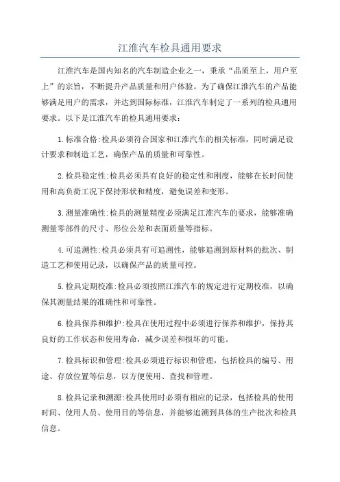
江淮汽车检具通用要求江淮汽车是国内知名的汽车制造企业之一,秉承“品质至上,用户至上”的宗旨,不断提升产品质量和用户体验。
为了确保江淮汽车的产品能够满足用户的需求,并达到国际标准,江淮汽车制定了一系列的检具通用要求。
以下是江淮汽车的检具通用要求:1.标准合格:检具必须符合国家和江淮汽车的相关标准,同时满足设计要求和制造工艺,确保产品的质量和可靠性。
2.检具稳定性:检具必须具有良好的稳定性和刚度,能够在长时间使用和高负荷工况下保持形状和精度,避免误差和变形。
3.测量准确性:检具的测量精度必须满足江淮汽车的要求,能够准确测量零部件的尺寸、形位公差和表面质量等指标。
4.可追溯性:检具必须具有可追溯性,能够追溯到原材料的批次、制造工艺和使用记录,以确保产品的质量可控。
5.检具定期校准:检具必须按照江淮汽车的规定进行定期校准,以确保其测量结果的准确性和可靠性。
6.检具保养和维护:检具在使用过程中必须进行保养和维护,保持其良好的工作状态和使用寿命,减少误差和损坏的可能。
7.检具标识和管理:检具必须进行标识和管理,包括检具的编号、用途、存放位置等信息,以方便使用、查找和管理。
8.检具记录和溯源:检具使用时必须有相应的记录,包括检具的使用时间、使用人员、使用目的等信息,并能够追溯到具体的生产批次和检具信息。
9.检具故障排查和处理:检具出现故障时,必须及时进行排查和处理,确保其正常使用和工作效率。
10.检具培训和技能提升:检具使用人员必须接受相应的培训和技能提升,提升其对检具的操作技能和质量意识。
总之,以上是江淮汽车的检具通用要求,江淮汽车通过严格的检具管理,确保产品的质量可控,提升用户满意度,为客户提供更好的产品和服务。
汽车车身覆盖件检具设计技术要求【完整版】(文档可以直接使用,也可根据实际需要修订后使用,可编辑放心下载)检具技术要求目录1. 目的 (3)2. 适用范围 (4)3. 责任 (4)4. 规定 (4)4.1 检具〔测量支架〕的概述 (4)4.2 检具设计与制造的技术要求 (4)4.3 检具和测量支架的验收和交付 (13)5. 存档 (14)6. 评审与更改 (14)7. 分发 (14)8. 附件清单 (14)附件一:关于检具定位销和检验销的说明 (15)1. 检具定位销概述 (15)2. 定位销A1的结构形式 (17)3. 定位销A2的结构形式 (19)4 . 零件检查销的结构和计算 (23)5. 轴套结构图示介绍 (26)附件二:检具(测量支架)认可流程 (28)附件三: 检具(测量支架)设计认可报告 (29)附件四:检具〔测量支架〕制造认可报告 (30)1. 目的通过制订?检具(测量支架)技术要求?,使检具(测量支架)在规划、设计与制造、验收与使用时,能够遵循统一的技术标准和评价指标。
2.适用范围本技术要求适用于车身检具及对零件型面尺寸或装配尺寸与车身坐标系统有关联的内外饰件的检具。
3. 责任***负责本技术要求的编制、维护、升级及分发等工作。
***零件供给商负责本技术要求在检具(测量支架)规划、设计、制造、验收和使用过程中的贯彻和执行。
4. 规定4.1 检具〔测量支架〕的概述检具〔测量支架〕的定义检具是一种用来测量和评价零件尺寸质量的专用检验设备。
在零件生产现场, 通过检具实现对零件的在线检测,为此需要将零件准确地安装于检具上, 然后通过目测,或测量表,或卡尺对零件型面,周边进行检查,也可以借助检验销或目测对零件上不同性质的孔及零件与零件之间的联接位置进行目检,从而保证在试生产及起步生产时实现零件质量状态的快速判断。
在此情况下,通过目检或测量可以判断: 零件轮廓周边大小和形状区域以及相对位置与通过CAD/CAM直接加工的检具理论值之间的偏差。
检具标准前言1996年,来自GM卡车集团、中等/豪华及小型汽车集团的代表成立了一个开发小组,对GM的生产件供应商检具标准进行了重新编制。
GM给生产件供应商的检具标准是为了建立GM 供应商PPAP检具全球性的公用标准而开发的。
另外,在开发过程中,还得到了Saturn、GM动力总成和GM加拿大集团的合作。
XXX 的检具标准是依据GM生产件供应商的检具标准,另外通过近几年对国内生产件供应商检具认证过程中,所积累的经验,同时结合国内的具体情况,对原来的GM生产件供应商检具标准进行了补充,为国内生产件供应商的PPAP所要求的检具认证制定了标准。
目录标题页次更改信息 3 I.序言 4 II.零件供应商的责任 5 III.设计概念 6 IV.概念批准7 V.设计要求7 VI.制造要求10 VII.认证要求12 VIII.检具重复性和再现性的要求13 IX.检具最终批准 15 X.保养要求15 XI.术语15 XII.附录A 17 XIII.附录B 18 XIV.附录C19更改信息版本日期段落条目1.0 12/1997 发布2.0 08/2002 发布3.0 03/2005 发布本标准中如发生任何更改都将记录在本页中。
当发生新的更改时,在保留本页清单原有记录的基础上,再增加新的更改内容。
修订后的版本将以版本1.0、2.0、3.0的顺序发布。
当不同的版本发布时,通过参照段落和条目的相应内容,可迅速找出更改内容。
本文件替代下列文件:•卡车和客车检具/量具标准(T& B 391)、12月、1989。
•中等/豪华汽车集团检具设计/制造标准,4月,1996。
I.序言A.介绍依照,先期产品质量策划手册(APQP)和生产件批准程序(PPAP)的要求,每当需要时,零件供应商应按照他们的质量计划获取检具来检验他们的产品。
生产件供应商在对XXX 的零件的检具进行报价、设计和制造时,除了使用他们自己的标准和要求外,还要参照本手册。
检具查收标准一.检具精度检具精度要求以下表:序号零件名称1底板2丈量基准块3定位基准块4模拟块、卡板5检测块(销)、定位销6其余型面7目视孔8检具附件形状地点名称技术参数(单位:mm)平面度0.05/1000垂直度0.05/1000平行度0.05/1000粗拙度< Ra1.6百格线轮廓度0.2丈量基准孔地点度0.02粗拙度< Ra1.6定位基准孔地点度0.05定位基准面廓度0.05粗拙度< Ra1.6检测面轮廓度0.1检测孔地点度0.1(产品孔地点公差小于1mm 时采纳十分之一原则)检测卡板线轮廓度0.15粗拙度< Ra1.6功能部位大小尺寸0.02导向部位与孔配合空隙< 0.015粗拙度< Ra1.6轮廓度0.2粗< Ra3.2度地点度2粗拙度< Ra1.6面差规±0.02二.构造要求1.底板1.1 底板上起码设置 3 个基准块,基准块需加不锈钢T 型钢套和保护罩,并注明坐标原点、坐标方向及坐标原点与汽车坐标原点的相对坐标值;1.2 检具基准块需设在底板周围三个角上并标有坐标值,不得直接设在底板上,检具的基准块依据左上、左下、右下地点进行设置,基准块中心距离检具底板边缘 50mm,如图 1 和图 2 示:图 1基准散布表示图1图2基准散布表示图21.3 上汽大众一级件检具一定设置两套丈量基准,一套设置在底板四个角,如图3,由 NC加工,另一套按 1.1 和 1.2 制作;图3检具底板11.4 底板上刻注车身坐标线及 X、Y、Z坐标值,车身坐标线以 X、Y、Z基准面为出发面 , 每隔 100mm或50mm为一档进行刻注,如图 3,划线深度和宽度均为 0.5 mm,刻线须涂红(客户对颜色有要求时按客户要求涂色),如客户对百格线有特别要求,按客户要求制作;1.6 除客户要求外,检具重量≤40KG时底板双侧须安装金属把手,如图3,检具重量> 40KG时底板上须安装吊环或吊耳,如图 4 和图5,检具起吊时吊绳与检具本体不得存在干预;图4检具底板2图5检具底板32.模拟块、卡板2.1 模拟块表面须刻上边差、空隙标准值并涂红(客户对颜色有要求时按客户要求涂色),如面差0mm,空隙 3mm,如图 6:图 6模拟块表记2.2 两模拟块之间空隙不得大于2mm,如图 7:图 7模拟块间距2.3 产品拐角处的模拟块不得断开,须做成一体式,如图7 所示;2.4 可拆模拟块须刻上名称,在检具上设置保存盒,并在保存盒上或盒旁设有安装表示图;2.5 两相连模拟块之间不得有显然面差;2.6 模拟块与其余本体及产品之间不可以存在干预;2.7 手持模拟块须刻上对应产品名称、图号及尺寸规格,除构造没法优化外,原则上重量≤ 3kg,手持模拟块一定设置保存箱;2.8 每一卡板上都需刻上设计尺寸规格,卡板检测部位放电加工或切削加工后确保 3mm的加工结果,如图8 所示图8卡板3.双开机构3.1 双开机构开关须顺畅,力度适合,装件不得有松动,开关上须刻上“装件”和“取件”表记,如图 9 所示;图 9双开机构开关3.2 机构定位面上须刻上基准表记并涂红(客户对颜色有要求时按客户要求涂色),两定位表面不得有显然面差,如图 10 蓝色面和红色的面不得有显然面差;图 10双开机构4.压紧机构4.2 压紧机构压头一定垂直于产品受压点;4.3 压紧次序需在压紧夹或支架上表示;4.4 压紧机构的设置需保证不影响产品的取放、丈量及CMM丈量;4.5 压紧机构在工作时不得与检具本体及产品存在干预;5.检测销、定位销5.1 手柄部用双斜纹滚花加工或六角柱体,表面须刻上检测和定位部位规格值及检测和定位表记,如图11;图 11检测销表示图5.2 为防备销子丢掉用伸缩绳固定在本体上,使用伸缩绳不要有阻碍,且尽可能短;5.3 销子插入应平顺,且无松动;5.4 伸缩绳固准时,销子应能自由活动,不会影响销子转动;5.5 为保证产品定位的稳固性,定位销一定完整贯串产品,所以产品定位销定位部分长度 H一定大于产品的厚度h,如图 12 所示;图 126.附件6.1 通止规、面差规、百分表等附件须齐整搁置在底板上;一般检具台车总高 800mm左右,大型总成检具在总高不超出 1400mm前提下制作台车,台车须万向轮和定向轮各两个,如图 13 和图 14图 13 台车小轮布局图 14 台车小轮表示图6.3全部检具一定装备防尘罩,防尘罩一定能防水、防尘、遮阳;6.4当客户有要求时检具需装备木箱,检具安置在木箱内须固定死,不得有松动,木箱外侧一定犹如图 15 所示表记;图 15三防表记三.外观要求1.百格线、刻线及附件油漆颜色须切合客户要求;2.无漏打定位销,定位销不得松动,保证定位销不是盲销;3.全部锁紧螺栓须装备弹簧垫,抽查螺栓锁紧力度,保证螺栓锁紧;4.检具本体及附件不得超出底板界限;5.表面无显然碰伤划伤,表面洁净整齐;6.检具不得使用垫片调试,更不同意垫片漏在表面;7.铭牌信息须正确;8.检具全部铁件表面须做表面办理,以保证防锈、防腐、硬度等要求;9.模拟块、支撑块及底板等全部能接触到的表面须倒角,以保证不伤人;10.铸铝底板及框架不得有> 2mm气孔、砂眼、结疤等缺点;11.模拟块及基准块上需将设计表记(空隙、面差、公差值、基准名称等表记)刻出,不同意表记使用贴纸粘贴,免得时间久而零落;四.资料检具查收资料分电子版(光盘刻录)和纸质版,详细清单以下:电子版:3D 数模( UG格式和 IGRES格式)最后检具设计图纸( CAD格式)《检具 CMM丈量报告》《检具销检报告》《检具 MSA报告》(客户有专用格式,按客户格式做)《检具设计方案》(客户有专用格式,按客户格式做)《检具操作说明书》(客户有专用格式,按客户格式做)检具设计认同表、检具制造认同表纸质版:检具总装图纸《检具 CMM丈量报告》(须是彩色的)《检具销检报告》《检具 MSA报告》(客户有专用格式,按客户格式做)《检具设计方案》(客户有专用格式,按客户格式做)《检具操作说明书》(客户有专用格式,按客户格式做)检具设计认同表、检具制造认同表。
检具标准上海通用汽车有限公司(SGM)检具标准上海通用汽车有限公司(SGM)前言豪华及小型汽车集团的代表成立了一个开发小组,对卡车集团、中等/1996年,来自GM给生产件供应商的检具标准是为了建的生产件供应商检具标准进行了重新编制。
GMGM检具全球性的公用标准而开发的。
另外,在开发过程中,还得到了PPAP立GM供应商加拿大集团的合作。
、GM动力总成和GMSaturn b5E2RGbCAP生产件供应商的检具标准,另外通过近几年对国内生产件GMSGM的检具标准是依据生产件GM 供应商检具认证过程中,所积累的经验,同时结合国内的具体情况,对原来的所要求的检具认证制定了标准。
PPAP供应商检具标准进行了补充,为国内生产件供应商的p1EanqFDPw目录标题页次3 更改信息4 序言I.II. 5零件供应商的责任 6 III. 设计概念概念批准IV. 7V. 设计要求7VI. 10 制造要求认证要求12 VII.检具重复性和再现性的要求13 VIII.15 IX. 检具最终批准15 X. 保养要求15 XI. 术语17 A XII. 附录18XIII. 附录BC19附录XIV.更改信息1 / 14版本日期段落条目发布 1.0 12/199708/2002 2.0发布DXDiTa9E3d03/2005 3.0发布RTCrpUDGiT本标准中如发生任何更改都将记录在本页中。
当发生新的更改时,在保留本页清的顺、3.0单原有记录的基础上,再增加新的更改内容。
修订后的版本将以版本1.0、2.0序发布。
当不同的版本发布时,通过参照段落和条目的相应内容,可迅速找出更改内容。
5PCzVD7HxA本文件替代下列文件:。
月、1989、卡车和客车检具/量具标准(T& B 391)12。
/豪华汽车集团检具设计/制造标准,4月,1996 中等序言I.介绍A.和生产件批(APQP)依照上海通用汽车有限公司(SGM),先期产品质量策划手册零件供应商应按照他们的质量计划的要求,每当需要时,准程序(PPAP)获取检具来检验他们的产品。
具标准开发小组,对GM的生产件供应商检具标全球性的公用标准而开发的。
另外,在开产件供应商检具认证过程中,所积累的经内生产件供应商的PPAP所要求的检具认具标准页次345677101213141517海通用汽车有限公司(SGM)检具标准更改信息本日期段落条目0 12/97 发布0 08/02 发布标准中如发生任何更改都将记录中。
当发生新的更改时,在保留本原有记录的基础上,再增加新的更。
修订后的版本将以版本 1.0、3.0的顺序发布。
当不同的版本发通过参照段落和条目的相应内容,找出更改内容。
替代下列文件:和客车检具/量具标准(T& B,1989年12月;等/豪华汽车集团检具设计/制造标996年4月。
具标准程序(PPAP)的要求,每当需要时,零件己的标准和要求外,还要参照本手册。
检测条件来修改此标准,但只在有相应准应用于在制造过程或分总成的检测中。
造和评价上海通用汽车有限公司(SGM)检具标准II. 零件供应商的责任A. 如果需要检具,零件供应商对检具获得过程的所有要素应负直接的责任。
另外,零件供应商必须保存所有相关活动的文件。
由于本文所涉及的零件情况的不尽相同的复杂性,供应商必须会同采购部门决定SGM SQE和SGM检具工程师如何适时地适度地参与。
B. 供应商应保证检具符合下列条件:1. 时间进度要符合整个项目的时间节点,如适用,包括GP-11。
2. 与被测零件的使用功能相符合。
3. 通过遵循定位基准方案,使检具符合被测零件的几何尺寸和公差图纸(GD&T)。
4. 如适用,应在检具中包括关键产品特性的测量。
5. 如要求,应包括能进行测量系统分析(MSA)的定量型数据采集装置。
6. 应具有辨别被测零件相对于名义值的变差的能力。
C. 依据QS-9000,要素4.11,供应商应建立并保持用于测量系统控制的编制成文件的程序。
此文件应包括该检具的:1. 尺寸测量报告,最好使用三坐标测量仪(CMM)。
汽车钣金件检具设计规范一、引言汽车钣金件是汽车车身的重要组成部分。
钣金件检具是用于对汽车钣金件进行检测和测量的工具和设备。
合理设计和使用钣金件检具对于确保汽车钣金件的质量和生产效率具有重要意义。
本文将对汽车钣金件检具的设计规范进行详细介绍。
二、设计原则1.安全性原则:设计应保证操作人员的安全,避免对操作人员造成伤害。
2.可用性原则:设计应便于操作和维护,操作人员能够方便地使用,维护人员能方便地维护和修理。
3.准确性原则:设计应保证测量结果的准确性和可靠性,确保钣金件的质量。
4.经济性原则:设计应尽量减少成本,提高生产效率。
三、设计要求1.结构合理:设计应考虑钣金件的形状和尺寸,并根据实际需要进行调整和优化,使检具能够完全契合钣金件,在测量过程中不产生变形和偏差。
2.材料选择:应选择耐磨、耐腐蚀、强度高的材料,以确保检具的使用寿命和稳定性。
3.制造工艺:应使用先进的制造工艺,如数控加工、激光切割等,以确保检具的精度和稳定性。
4.易操作性:设计应便于操作人员进行操作和调整,并能够快速准确地测量和判断钣金件的合格与否。
5.易维护性:设计应便于维护人员进行维修和保养,并能够快速诊断和排除故障。
6.标准化、模块化设计:设计应尽量做到标准化和模块化,以便于批量生产和维护,降低成本。
四、设计步骤1.确定检测要求:根据钣金件的形状、尺寸和检测标准,确定检具的具体检测要求。
2.设计检具结构:根据钣金件的特点和检测要求,设计检具的整体结构和各个部件。
3.选择材料和制造工艺:根据实际需要,选择合适的材料和制造工艺,并进行加工和制造。
4.进行测试和调整:对设计出来的检具进行测试和调整,确保其满足检测要求。
5.整理设计文档:对设计过程中的各个环节进行整理和归档,以备将来使用和维护。
五、质量控制1.原材料的质量控制:对检具所使用的各个原材料进行质量把控,确保其符合技术要求。
2.制造过程的质量控制:对检具的制造过程进行严格的质量控制,确保每个环节都符合技术要求。
To: All UsersFrom: Bill Bielby / John Wolf / Don Ellis Gage Process EngineersPhone:248-576-0775 / 248-576-5126 / 248-944-1072T/L: 776-0775 / 776-5126 / 754-1072CHAPTER 1.0INTRODUCTION1.1 GENERALThis standard provides a common gage standard used by all DaimlerChrysler Engineering Departments except Power Train Engineering. This standard supersedes previous releases of the AME Gage Standard (GED0C001) back to Rev.9-98.This standard gives the gage source guidance in the requirements for design, build, inspection and certification of DaimlerChrysler gages to check all body-in-white, trim and chassis components. These DaimlerChrysler Gage Standards shall be adhered to for all gage fixtures.DaimlerChrysler is supporting the Tooling and Equipment Supplement to QS-9000. Seller must be third-part certified to either QS9000 TE Supplement (valid until December 15, 2006) orISO9001:2000, unless otherwise agreed to by DaimlerChrysler, International Procurement Services in writing. After December 15, 2006, third party certification for ISO9001:2000 will be required. Seller must obtain ISO9001:2000 certification from a TS16949 approved registrar and auditor. A list offTS16949 approved registrars is available at . Seller will supply evidence of the certification to DaimlerChrysler upon request.Deviations from these standards may be granted from the DaimlerChrysler Gage Process Engineer in writing and would be included with the standard as part of a specification package. All quotations shall then state that the gage fixture being quoted will be designed and built to the specification package and/or DaimlerChrysler Gage Standard.Design approval shall not constitute a waiver or guarantee of responsibility for any gage purchased by DaimlerChrysler Corporation. An approved gage design does not constitute a certified or functional gage.The Advance Manufacturing Gage Process Engineer has lead responsibility for all DaimlerChrysler user run plant gages.Appendix "A" defines the tasks required to design and build Outside Supplier Gages. The product releasing engineer has lead responsibility for the tasks identified in the Appendix "A".Only DaimlerChrysler approved/recommended design/build sources shall be used, unless agreed upon by the DaimlerChrysler Gage Process Engineer in writing using Waiver or Deviation request form from DaimlerChrysler Gage Process Engineer for approval consideration.=>For consideration to supply DaimlerChrysler Chrysler Group gage fixtures, request copy of "Request for Recommended DaimlerChrysler Gage Design / Build Source" document form: Request to ADD Gage Source v07 6-04.xls, from supplier's DaimlerChrysler Gage Process engineer contact for filing to initiate review process. Follow document's "Req(uest) Procedure" file tab to complete.For outside supplier gages, the Supplier shall notify the DaimlerChrysler Gage Process Engineer if he wishes to use a design / build source that is not on the approved / recommended source list (Refer to Gage Standard Section 12.0).1.2 GAGE STANDARDS FLOW CHART- ASME Gage Process will be responsible to chair and update DaimlerChrysler Design and Build Gage Standards.- Members of the standards committee will rotate between group personnel.- The standards committee will review all revisions to the standards before submitting for review and approval by BIW Gage Process, Stamping Gage Process and the user run plants.1.3 GAGE STANDARD CHANGE PROCEDURE:Standards to be reviewed yearly for update. And, semi-annually if updates are necessary.Gage standards change requests are to be submitted in MQAS through the "Document Change Request" (DCR) process form found in the "Released Documents" Lotus Notes database for document GEDOC001xx.All change requests will be submitted by a Gage Process Engineer for review.Addresses for viewing most current DaimlerChrysler ASME/AME Design and Build Gage Standards:Intranet Address./gages/index.htmInternet Address.https:///mfg/amedd/gages/index.htmContact DaimlerChrysler Gage Process Engineers for assistance.CHAPTER 2.0GAGE DESIGN2.1 General2.1.1All gage designs become the property of DaimlerChrysler.2.1.2Gage designs shall be a Computer Aided Design (CAD). Manual gage designs require approval by DaimlerChrysler. Gage designs that are required to be designed in CATIA Solid-E; see the DaimlerChrysler Gage Process Engineer for direction and approval.2.1.3All CAD gage designs will be formatted in CATIA at time of delivery. (DaimlerChrysler user run plants only).2.1.4Holding fixtures shall be designed in CATIA Solid-E for DaimlerChrysler user plants2.1.5All gages shall be designed in metric.2.1.6DaimlerChrysler Gage Process will conduct a design kick-off/line-up meeting with the gage manufacturer.2.1.7The design proposal shall have DaimlerChrysler approval at 40%, 90%, and 100% completion. The design source will submit one set of design plots for this review. All gage designs shall be signed-off by DaimlerChrysler Gage Process Engineer using the Gage Design Kick-off, Review, and Approval form (GEFM001xx).2.1.8a.) ASME: Preliminary Operation Description Sheets (ODS) are to be made available at the 90% design review for approval by DaimlerChrysler ASME Gage Process engineer.b.) AAME: Preliminary Automated Manufacturing Planning Sheets (AMPS) are created by DaimlerChrysler AAME Gage Process engineer with AMPS release two (2) weeks prior to V1 build when GR&R reports have been completed & passed using S2 metal for verification of clampingsequence.2.1.9The gage shall address all G, D, &T controls and "toleranced" surfaces as shown on the released part model.2.1.10Minimum material thickness shall be used for the gage design, construction and CMM programming.2.1.11Design Considerations:A. Operator and maintenance personnel safety.B. Simplicity in operator part loading without restrictions or interferences.C. Free accessibility to all components for ease of maintenance and replacement.D. Rigidity of construction for operation endurance for the life cycle of the vehicle.2.1.12After all issues from the 40% and 90% design reviews are resolved, the gage manufacturer is authorized to begin build. This authorization is documented on the Gage Design Kick-off, Review, and Approval Form (GEFM001xx) and is signed by the lead DaimlerChrysler Gage Process Engineer.2.1.13Upon shipment of the gage fixture to the DaimlerChrysler User Run Plant, the designs are updated and to include gage fixture dimensions and weight. Then, ship designs as directed by DaimlerChrysler Gage Process Engineer.2.2 Design Layout Requirements2.2.1The fixture base will be parallel to the X, Y, or Z plane of vehicle. Base orientation will be determined by the DaimlerChrysler Gage Process Engineer.2.2.2Alignment features shall be shown on the gage drawing, targets and tooling balls.2.2.3All gage designs shall be identified with DaimlerChrysler Gage Numbers as shown on the MEDDS specification for each design. Utilize the standard stock list (Figure 2.2a).The base height shall be determined by the average inspection height of 1000.0 mm.2.2.5All math models required for the gage design shall be listed in the space provided. List part number, drawing or layout number, name and latest change (Figure 2.2a).2.2.6List name, address, and phone number of manufacturer/supplier of all purchased parts on gage drawing. (Reference: stock list).2.2.7List DaimlerChrysler commodity codes in the Standard Stock List. (DaimlerChrysler Design & Build ONLY. See DaimlerChrysler Gage Design or Process Engineer.)2.2.8All bases larger than 48 inch x 48 inch will have legs and must be steel, unless otherwise noted by DaimlerChrysler Gage Process Engineer.2.3 Design Status2.3.1Design status reports are required weekly as directed by the DaimlerChrysler Gage Process Engineer.2.3.2Reporting Percentage Milestone Criteria:10% Placed. (Supplier has part information. Job has been started.)40% Design ready for review and approval (Job is laid out. Material is being ordered.)90% Design ready for final review (complete), buy-off, and ship to build source.100% Design complete including any build changes and archived at DaimlerChrysler.2.3.3 New Model Planning Reporting Standards: (MEDOC001 xx)Reporting standards are to reference New Model Planning (NMP) document (MEDOC001 xx) for uniform reporting percentages on gage fixtures.(See MEDOC001.xls insert)2.4 Recording Design RevisionStandard stock list sheet shall be the sheet used for all revisions. It shall indicate the latest revision, revision date, and revision authority. The stock list shall accompany design to the build source.2.4.2All Revisions will be written clearly and completely. Write revisions per sub-models affected. (Reference Figure 2.2a.)Example: Detail X Sub-model XXXXX Form revise; Hole relocated.2.4.3All designs shall be updated to include changes made during construction and noted in the change column.2.4.4Gage design or construction changes are not to be made without DaimlerChrysler Gage Process Engineer authorization.If changes are required after the GR/GR&R study is completed, the ODS shall be updated prior to shipment of gage fixture to the user run plant.2.4.5Design revision Change Letters:- First change letter used is "A".- All following change letters are used consecutively.- No change letter shall be skipped, except the letters "I", "O" and "Q".- Design revisions will carry a common change letter on every sheet involved in aparticular revision.2.4.6Changes shall reference the manufacturing Change Notice (CN)number and part engineering change (EC) level.Figure 2.2a Stock ListCHAPTER 3.0MANUAL GAGE DESIGN3.1 GeneralNote: Manual gage designs require approval by DaimlerChrysler3.1.1Body lines shall be called out and stamped on finish adjacent edges of base, and the units that are mounted to the base.3.1.2Use color for all part lines. A different color shall be used for each part. The identification of a part shall be called out at least once on each gage design.3.1.3Identify net areas of the gage with cross-hatching.3.1.4Identify materials being used in cross sections, with cross hatching.3.1.5Diamond characteristics identify on appropriate views and section.3.2 Layout Format3.2.1The gage design layout shall conform to and contain the information as contained in Standard Stock List.3.2.2Change balloons shall be used with all revisions on layouts, stock list and on borderline.3.2.3Use a 10.0 mm diameter balloon for change letters.3.2.4The minimum sheet size is "D" size, 24.0 inch x 36.0 inch.3.2.5The maximum length of a sheet shall be 12.0 feet, with a maximum width of 42.0 inches.3.2.6All sheets shall have a 0.50 in. border all around.3.2.7Designs shall be full size, unless otherwise specified.3.2.8Major panel designs shall have a key sheet which may be at a reduced scale.3.2.9A full plan view of the part and gage base is required on fixtures that are symmetrical about the centerline. The gage design shall show and detail the Right Hand side of fixture and any Left Hand only details.3.2.10Centerline and body lines shall be shown in three planes and in all views and sections. To front "O" line, to centerline of body and to bottom "O" line.3.2.11Start dimensions shall be shown in three planes; in full metric dimensions, at the right lower side of plan view for right hand fixtures, and left lower side of plan view for left hand fixtures.3.2.12The stock list shall list stock size, not name of detail, except for weldments, which shall be listed as "welded construction". Note: Always use standard manufactured stock sizes.3.3 Manual Design Sections3.3.1The gage design shall show plan, front, end views and all other views and sections necessary to clarify design.3.3.2On drawings requiring sections, start with section letter "A" and continue through the alphabet in order. Exceptions shall be for the letters "I", "O", and "Q". Also, list the sheet number where the section can be found. On the sheet with the section, indicate where the section is taken from.3.3.3All sections shall be full size or larger and noted. Any section that shows sheet metal shall beidentified by part number.3.3.4All sections shall be cut normal to part surface.3.4 Manual Design - Sheet Numbering3.4.1Sheet Numbers & Type of Drawings:Sheet #1 - Key sheet or layout sheet.Sheet #2 - Stock list (standard form)- Sheet #2a, 2b, 2c, etc. = Stock list continuation sheets.Sheet #3 - Additional layout or detail sheets.3.4.2Numbering for unitized drawings:Sheet 101 ( unit 1, sheet 1) General Layout.Sheet 102 (unit 1, sheet 2) General Layout or detail.Sheet 103 (unit 1, sheet 3) Bill of Materials (if required).Sheet 104 (unit 1, sheet 4) and higher as required.Sheet 1401 (unit 14, sheet 1) example of unit 14.Sheet 1401 (unit 14, detail #14001, unit 1, detail #1001).3.5 Detail Identification-Details symmetrically opposite on separate bases (use same number)1 REQUIRED SAE1018WELDED CONSTRUCTION AS SHOWNFOR RH FIXTURE 1 REQUIRED SAE 1018WELDED CONSTRUCTION SYMMETRICALLY OPPOSITE FOR LH FIXTURE-Details not symmetrically opposite (Use separate numbers).Detail 27-BRACKET (NORM)1 REQUIRED SAE 1018WELDED CONSTRUCTION FOR RH FIXTURE ONLY Detail 28-BRACKET (NORM)1 REQUIRED SAE1018WELDED CONSTRUCTION FOR LH FIXTURE ONLY-RH and LH Details on the same base (Use separate numbers).1 REQUIRED SAE1018 WELDED CONSTRUCTIONAS SHOWNFOR RH SIDE 1 REQUIRED SAE 1018WELDED CONSTRUCTION SYMMETRICALLY OPPOSITE FOR LH SIDECHAPTER 4.0COMPUTER AIDED DESIGN (CAD)4.1 General4.1.1The design shall adhere to DaimlerChrysler supplied product math model, and the MEDDS / AMPS detailing gage concepts.4.1.2Detailing is not required for CAD design, unless requested by DaimlerChrysler Gage Process Engineer.4.1.3CAD model of compatible references are furnished, when available (for reference only).4.1.4Designs shall be broken into sub-models. Each sub-model will consist of one complete stack of gage fixturing from product surface to base surface. For DEA flexible tooling, each module assembly shall have its own sub-model, using a unitized system.4.1.5CAD model shall be 3D & CNC compatible.4.1.6Details shall be identified in 3D wire frame model with a 3D number or CATIA attribute. Note a start point indicating orientation of the detail and the appropriate gage symbol indicating net, flush, feeler, etc.4.1.7CAD models shall be separable, individual details shall be in separate layers (base, clamps, composite, etc.)4.1.8Each CAD model shall be a complete representation of the finished fixturing for that sub-model, showing open position of clamps, templates, etc.4.1.9Designs may be completed in wire frame or CATIA Solid-E, as specified in process specification package.4.1.10When designing in wire frame, tapped holes and dowel holes shall be represented by a circle of the same exact diameter as hole. The circle shall be placed on the face of the detail where screw or dowel would enter. Counter bored holes shall have actual depth shown on the design. [Use Mt. Elliot Tool & Die (METD) tool design document, TEDOC004 xx, for color code reference for hole attributes. See DaimlerChrysler Gage Process Engineer.]4.1.11When designing in CATIA Solid-E, tapped holes should be represented by tap drill size with wire frame circle the exact diameter as tap. [Use Mt. Elliot Tool & Die (METD) tool design document, TEDOC004 xx, for color code reference for hole attributes. See DaimlerChrysler Gage Process Engineer.]4.1.12For wire frame designs, provide face definitions for periphery, flush, feeler, and net surfaces.4.1.13The gage shall be designed for N/C machining and shall be able to maintain dimensional integrity while being machined.4.2 CAD File Format for non-VPM users4.2.1Establish the CAD file using the following format: \Example #1: The file name for an inspection model is given as: S7FTAN55255516AA_AR_S01R_REL. The file name is defined as:S = Stamping Tool Gage.7 = Model Year of product; 1997.FT = Flexible Tool Gage.AN = Body style.55255516AA = Part number.AR = Product change level, "AR".SO1R = Sub-model S01 Right Hand.REL = Gage design change level "Release."Example #2: The file name for an inspection model is given as: A7QRS3400_REL_S01_AThe file name is defined as:A = Assembly Tool7 = Cube Tool for 1997 RSQ = Cube Tool fixture.RS = Body style.3400 = Area number.REL = Product Change Level ReleaseS01 = Sub model S01A = Tool design Change Level, "A".4.2.2When CATIA CAD designs are created for DaimlerChrysler checking fixtures, creation of symmetrically opposite models is not required. The following guidelines are examples for symmetrical and asymmetrical fixtures.Example #1: R1 Stamping Fixture for Panel Door Inner which is right hand shown, left hand symmetrically opposite.Part Info for Example #1:Part #55251234AA Rt. Engineering Change Level "D"Part #55251235AA Lt. Design Change Level "REL"MY/VF 1998 DNOnly models for the right hand fixture are required.The file name should contain both right hand and left hand part numbers. "RL" shouldfollow the base and sub-model identification, which designate the model as being righthand shown with the left hand symmetrically opposite.S8RDN55251234-5AA_D_STKLIST_RELS8RDN55251234-5AA_D_R1ODS_RELS8RDN55251234-5AA_D_BASERL_RELS8RDN55251234-5AA_D_S01RL_RELExample #2: R1 Stamping Fixture for Panel Rear Qtr. Otr. which is right hand shown, left hand symmetrically opposite except as shown.Part Info for Example #2:Part #55255678AA Rt. Engineering Change Level "C"Part #55255679AA Lt. Design Change Level "REL"MY/VF 1998 DNAll models for the right hand fixture are required.Only non- symmetrically opposite models are required for the left hand fixture.The filename should contain both right hand and left hand part numbers. "RL" shouldfollow the sub-model identification, which designate the model as being right hand shown with the left hand symmetrically opposite. "R" should follow the sub-model identification,which designates the model as being right hand only. "L" should follow the sub-modelidentification, which designates the model as being left hand only. The base sub-modelshould be followed with the appropriate designation of "RL", "R" or "L".Note: The left hand model should be created on the left hand side.S8RDN55255678-9AA_C_STKLIST_RELS8RDN55255678-9AA_C_R1ODS_RELS8RDN55255678-9AA_C_BASERL_RELS8RDN55255678-9AA_C_S01RL_RELS8RDN55255678-9AA_C_S02R_RELS8RDN55255678-9AA_C_S02L_RELExample #3: R1 Stamping Fixture for Panel Cowl Side which is right hand shown, and left hand is significantly different to justify a separate design.Part Info for Example #3:Part #55253456AA Rt. Engineering Change Level "C"Part #55253457AA Lt. Design Change Level "REL"MY/VF 1998 DNAll models for the right hand fixture are required.Filename should contain only the right hand part number for the right hand part. "R" should follow the base and sub-model identification, which designates the model as being righthand only. Filename should contain only the left hand part number for the left hand part."L" should follow the base and sub-model identification, which designates the model asbeing left hand only. Note: The left hand model should be created on the left hand side.Both designs require their own stock list and Operational Description Sheet (ODS).S8RDN55253456AA_C_STKLIST_RELS8RDN55253456AA_C_R1ODS_RELS8RDN55253456AA_C_BASER_RELS8RDN55253456AA_C_S01R_RELS8RDN55253456AA_C_S02R_RELS8RDN55253457AA_C_STKLIST_RELS8RDN55253457AA_C_R1ODS_RELS8RDN55253457AA_C_BASEL_RELS8RDN55253457AA_C_S01L_RELS8RDN55253457AA_C_S02L_RELExample #4: R1 Stamping Fixture for Panel Hood Inner which is right hand side shown, left hand side symmetrically opposite.Part Info for Example #4:Part #55259876AA Engineering Change Level "D"MY/VF 1998 DN Design Change Level "REL"Only models for the right hand side of fixture are required."RL" should follow the sub-model identification, which designate the model as being righthand shown with the left hand symmetrically opposite. "R" should follow the sub-modelidentification, which designates the model as being right hand only. "L" should follow thesub-model identification, which designates the model as being left hand only. No letterdesignation is required for base or sub-models which are a center line models.S8RDN55259876AA_D_STKLIST_RELS8RDN55259876AA_D_R1ODS_RELS8RDN55259876AA_D_BASE_RELS8RDN55259876AA_D_S01RL_RELS8RDN55259876AA_D_S02R_RELS8RDN55259876AA_D_S02R_RELS8RDN55259876AA_D_S03_D_RELExample #5: R1 Stamping Fixture for Panel Dash which is non-symmetrical across centerline.Part Info for Example #5:Part #55255432AA Engineering Change Level "D"MY/VF 1998 DN Design Change Level "REL"All models of the fixture are required.No letter designation is required for base or sub-models.S8RDN55255432AA_D_STKLIST_RELS8RDN55255432AA_D_R1ODS_RELS8RDN55255432AA_D_BASE_RELS8RDN55255432AA_D_S01_RELS8RDN55255432AA_D_S02_REL4.3 CAD File Format for VPM users.4.3.1 See DaimlerChrysler Gage Process Engineer for instructions, access privileges, etc.(GEDOC001 08.1) Rev.08.1 7-2005 - DaimlerChrysler Uncontrolled Document - ASME/AME Gage Standards Chapter 5CHAPTER 5.0BASES5.1 General5.1.1The base shall be sized so that all clamps and targets do not overhang the periphery of the base when in the open position. Also, there shall be sufficient surface provided on the base for mounting interchangeable tooling, inspection equipment and a DaimlerChrysler identification plate.5.1.2The base height shall be determined by the average inspection height of 1000.0mm5.1.3The part shall be a minimum of 100.0 mm above base, except CMM holding fixtures (refer to Section 6.13).5.1.4Machined surfaces of bases shall be rust-proofed.5.1.5All tooling plate gage bases shall have jig feet in the four corners.5.1.6Floor bases shall have provisions for leveling, utilizing all base pads include details in stock list.5.1.7Sub-base construction with multiple units shall utilize machined corners on the sub-base when units are doweled at assembly. Sub-base corners shall be labeled/stamped.5.1.8Base's leg, or cart if base size is less than 48 inch x 48 inch, requirements shall be finalized with the user run plant at the 40% design review and noted in the MEDDS specification.5.1.9Legs for bases will be itemized in fixture stock list.5.1.10Legs or carts are to be shipped to the user run plant only. Do not ship to tryout sources.5.1.11All legs will have leveling screws.5.1.12Holes for attached legs shall be provided; legs shall be shipped unassembled from base.5.1.13The material for cast aluminum bases shall be SAE 315 or equivalent; with Brinell hardness of 74. The average yield strength shall be 26,000 PSI and a tensile strength of 35,000 PSI. Supplier shall furnish their own pattern.5.1.14All bases shall be machined on two adjacent edges.5.1.15All steel bases shall be stress relieved5.1.16All aluminum bases shall be normalized.5.2 Base Sizes:5.2.1Aluminum S t e e lBase Size (base must fit within parameters in both directions)Base Material Base Size (basemust fit withinparameters in bothdirections)Base Material6.0 in x 6.0 in to 6.0 in x 12.0 in 1.0 in aluminum tooling plate,Blanchard ground flat & parallelto +/- 0.05 mm overall18.0 in x 12.0 in to18.0 in x 18.0 in0.75 in Thick (clean up) B.P.with Jig Feet 1.50 in x 1.50 in x0.44 in12.0 in x 8.0 in to 12.0 in x 16.0 in 1.0 in aluminum tooling plate,Blanchard ground flat & parallelto +/- 0.05 mm overall18.0 in x 24.0 in to18.0 in x 30.0 in1.0 in Thick (clean up) B.P. withJig Feet in x 1.50 x 0.44 in18.0 in x 12.0 in to 18.0 in x 18.0 in 1.0 aluminum tooling plate,Blanchard ground flat & parallelto +/- 0.05 mm overall with JigFeet 1.50 in x 1.50 in x 0.44 in24.0 in x 24.0 in to24.0 in x 36.0 in1.0 Thick (clean up) B.P. with3.0 in Channel all around 24.0in x 36.0 in 1.50.0 in from edgeof plate with (4) 0.75 in. Thickpads on corners18.0 in x 18.0 in to 48.0 in x 48.0 in Aluminum Casting30.0 in x 36.0 in to30.0 in x 42.0 in18.0 in x 30.0 in1.0 in Thick (clean up) B.P. with4.0 in Channel iron all around1.50 in from edge of plate with(Use mean thickness of web onchannel iron) (4) 0.75 in thickpads on corners36.0 in x 42.0 in to 36.0 in x 48.0 in Same as above except that maximum thickness for web channel iron to be used48.0 in x 48.0 in to 48.0 in x 84.0 in 1.25 in Thick (clean up) B.P. with 6.0 in channel all around 3.0 in from edge of plate plus sufficient channel braces and (4) 0.75 in thick 7.0 in x 7.0 in pads on corners. Legs and jack screws shall be provided on all four corners plus (1) in center of base48.0 in x 84.0 in to 48.0 in x 120.0 in Same as 48.0 in x 48.0 in except use 8.0 in channel iron48.0 in x 120. 0 in and over Same as 48.0 x 48.0 in except use 10.0 in channel iron. Provide for (6) legs and jack screws plus (1) in center of base5.3 Base Machined Tolerances5.3.1Overall "square- ness" relationship of machined edges, length, and width shall be +/- 0.08 mm.5.3.2Overall parallelism between top and bottom surfaces shall be +/- 0.08 mm.5.3.3Bases shall be flat within +/- 0.13 mm 0.13mm per square foot of area with a maximum of +/- 0.10 mm total in any length.5.3.4Base surface finish shall not exceed 80.0 micro inches RMS roughness.5.4 Line Blocks5.4.1Bases larger than 24 in. x 24 in. require a removable line block. (Figure 5.4a).5.4.2DaimlerChrysler Gage Process Engineer / user run plant determines line block or machine edge preference.5.4.3The hole pattern to locate line block around the gage shall have no more than 400.0 mm between locations.5.4.4Position line blocks outside of the gage and part.5.4.5Dowel holes in base for line blocks shall be reamed in steel bases and bushed in aluminum base construction. (Figure 5.4a).Figure 5.4a Line Block5.5 Hoist Ring Requirements5.5.1Supplier shall provide swivel clevis type hoist rings at the four (4) fixture corners if heavier than 60 pounds.5.5.2Hoist rings must have the load capacity to lift maximum weight of fixture plus 25%. Eye bolt size shall be determined by maximum load of eye bolts at a 60 degree pull angle.5.5.3The eye bolt size shall be stamped near the hole on the base.5.5.4Use Helicoil screw locks for aluminum bases.。