欧姆龙时间继电器选型
- 格式:doc
- 大小:12.00 KB
- 文档页数:1
欧姆龙继电器选型办法一、外形、设备办法、设备标准欧姆龙继电器的外形、设备办法、设备标准种类很多,用户有必要按整机的具体需求,提出具体的设备面积,容许继电器的高度、设备办法、设备标准。
这是挑选继电器首要要考虑的疑问。
以下几个疑问,选用时应予以留神:(1).对于PC板式引出脚;脚间隔大都为2.54×n(n=1、2、3……,以下同),如JZW5;也有2.5n,如JZG2-2/B;也有不符合标准间隔的继电器,如MR72。
引出脚的长度一般为3.5。
(2).引出脚的可焊性、继电器的抗焊接热、引出脚相对底座的不垂直度等应有严峻的需求。
(3).快联接式继电器;快联接引出脚一般有250#(6.35×0.8)、187#(4.75×0.5)2种。
这类引出脚要分外留神插拔力需求,250#引出脚:拔力矩十kg.cm;187#引出脚:拔力矩5kg.cm。
二、输入参量纷歧样种类的输入参量,是挑选欧姆龙继电器类型的首要依据。
多见的输入参量的种类有:(1).交流输入参量。
当输入参量为交流电压(电流)时,应选用交流继电器。
选用这一类型的继电器,应留神以下几个疑问:交流频率----交流继电器输入电压(电流)的频率一般为50HZ,或60HZ。
由于二者线圈的感抗纷歧样,吸动电压有明显差异。
合同中应予注明。
环境温度----交流继电器由于存在涡流损耗、磁滞损耗,继电器的温升较高,一般为70℃到80℃。
工作环境温度不宜过高,最好为40℃到65℃,判定环境温度的核算公式:t1≤t2-t3-150C;注:t1:继电器最高环境温度,0C;t2:漆包线、绝缘资料最高容许长时刻工作温度0C(B 级为1300C;F级为1550C)t3:继电器均匀温升,0C。
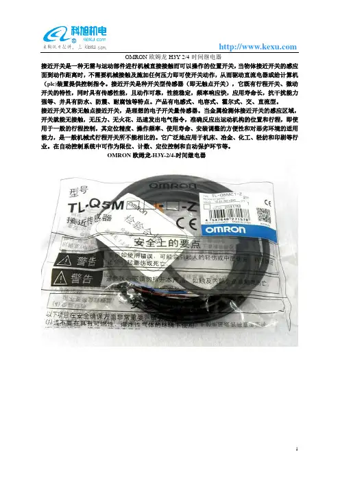
OMRON欧姆龙-H3Y-2/4-时间继电器
接近开关是一种无需与运动部件进行机械直接接触而可以操作的位置开关,当物体接近开关的感应面到动作距离时,不需要机械接触及施加任何压力即可使开关动作,从而驱动直流电器或给计算机(plc)装置提供控制指令。
接近开关是种开关型传感器(即无触点开关),它既有行程开关、微动开关的特性,同时具有传感性能,且动作可靠,性能稳定,频率响应快,应用寿命长,抗干扰能力强等、并具有防水、防震、耐腐蚀等特点。
产品有电感式、电容式、霍尔式、交、直流型。
接近开关又称无触点接近开关,是理想的电子开关量传感器。
当金属检测体接近开关的感应区域,开关就能无接触,无压力、无火花、迅速发出电气指令,准确反应出运动机构的位置和行程,即使用于一般的行程控制,其定位精度、操作频率、使用寿命、安装调整的方便性和对恶劣环境的适用能力,是一般机械式行程开关所不能相比的。
它广泛地应用于机床、冶金、化工、轻纺和印刷等行业。
在自动控制系统中可作为限位、计数、定位控制和自动保护环节等。
OMRON欧姆龙-H3Y-2/4-时间继电器。
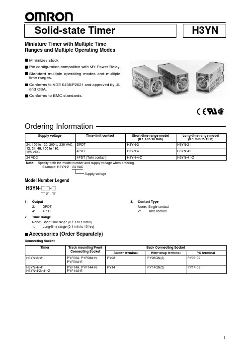
Solid-state Timer H3YN Miniature Timer with Multiple TimeRanges and Multiple Operating ModesMinimizes stock.Pin configuration compatible with MY Power Relay.Standard multiple operating modes and multipletime ranges.Conforms to VDE 0435/P2021 and approved by ULand CSA.Conforms to EMC standards.RCNote: 1.Single-phase, full-wave-rectified power supplies can be used.2.When using the H3YN continuously in any place where the ambient temperature is in a range of 45°C to 50°C, supply 90% to 110%of the rated supply voltages (supply 95% to 110% with 12 VDC type).3.Set the reset voltage as follows to ensure proper resetting.100 to 120 V AC:10 V AC max.200 to 230 V AC:20 V AC max.100 to 110 VDC:10 VDC max.Note:T erminal screw sections are excluded.Electrical Life Expectancy (Reference Value)H3YN-2/-21H3YN-4/-41H3YN-4-Z/-41-ZS w i t c h i n g o p e r a t i o n s (x 10 )3Load current (A)S w i t c h i n g o p e r a t i o n s (x 10 )3Load current (A)S w i t c h i n g o p e r a t i o n s (x 10 )3Load current (A)S w i t c h i n g o p e r a t i o n s (x 10 )3Load current (A)Reference:A maximum current of 0.6 A can be switched at 125 VDC (cos φ = 1).Maximum current of 0.2 A can be switched if L/R is 7 ms. In both cases,a life of 100,000 operations can be expected.The minimum applicable load is 1 mA at 5 VDC (P reference value).Reference:A maximum current of 0.5 A can be switched at 125 VDC (cos φ = 1).Maximum current of 0.2 A can be switched if L/R is 7 ms. In both cases,a life of 100,000 operations can be expected.The minimum applicable load is 1 mA at 1 VDC (P reference value).S w i t c h i n g o p e r a t i o n s (x 10 )3Load current (A)Reference:A maximum current of 0.5 A can be switched at 125 VDC (cos φ = 1).Maximum current of 0.2 A can be switched if L/R is 7 ms. In both cases, a life of 100,000 operations can be expected.The minimum applicable load is 0.1 mA at 1 VDC (P reference value).250 VAC, cos φ = 124 VDC, cos φ = 1250 VAC, cos φ = 0.424 VDC, L/R = 7 ms250 VAC, resistive load24 VDC, re-sistive load 250 VAC, cos φ = 124 VDC, cos φ = 1250 VAC, cos φ = 0.424 VDC, L/R = 7 ms5,0001,0005002005,0001,0005002005,0001,0005002005,0001,0005002005,0001,00050010060Run/Power Indicator (Green)(Lit: Power ON)Output Indicator (Orange)(Lit: Output ON)Main DialSet the desired time according to time range selectable by DIP switch.Power OutputIntervalRun/Power indica-Flicker OFF-startPowerOutputTime limit contact Run/Power indicator Time limit contact Flicker ON-startPower OutputTime limit contact Run/Power indica-Time limit contact Note:t:Set time Rt:Reset timeThe 1-s range and ON-delay mode for H3YN-2/-4/-4-Z, the 1-min range and ON-delay mode for H3YN-21/-41/-41-Z are factory-set before shipping.Time RangesH3YN-41-ZNote:The top two DIP switch pins are used to select the time ranges.Operating ModesH3YN-2/-21 Front MountingH3YN-4/-41 Front Mounting H3YN-4-Z/-41-ZMounting HeightPYF08A/PYF08A-N/PYF08A-E (PYF14A/PYF14A-N/PYF14A-E (see note))PY08 (PY14 (see note))PY08QN (PY14QN (see note))Note:Models in parentheses are Sockets connecting to the H3YN-4/-4-Z.Fourteen, 3 ×1.2 elliptic holes28 max.21.5 max28 max.21.5 maxH3YN Series H3YN SeriesH3YN SeriesPY08 (PY14)PY08QN (PY14QN)PYF08A (PYF14A)6.4(63)Connecting SocketsUse the PYF j A, PY j , PY j -02, or PY j QN(2) to mount the H3YN. When ordering any one of these Sockets, replace “j ” with “08” or “14.”Terminal Arrangement (T op V iew)Track Mounting/Front Connecting Sockets PYF08AEight, M3 ×8 semsTwo, 4.2 × 5mounting holesTwo, 4.5 dia.M4 or M3Mounting Holes672 max.23 max.30 max.16.535.43.44659±0.315±0.2PYF j A90.586.6H3YN SeriesTerminal Arrangement (T op V iew)PYF-14AMounting HolesFourteen, M3 ×8 semsTwo, 4.2 × 5mounting holesTwo, 4.5 dia.M4 or M3672 max.29.5 max.30 max.16.535.43.44659±0.322±0.2PYF-08A-NTerminal ArrangementMounting Holes(for Surface Mounting)4185129141413424412144111A2A2A1423222124434241441312111A2A2A1Terminal ArrangementMounting Holes(for Surface Mounting)PYF08A-E31 max.72 max.23 max.(Top V iew)PYF14A-E31 max.72 max.29.5 max.(TopView)Eight, M3 ×8 semsTwo, 4.2 × 5mounting holesTwo, 4.5 dia.M4 or M3Two, 4.5 dia.M4 or M3Two, 4.2 × 5mounting holesEight, M3 ×8 semsPanel CutoutBack Connecting Sockets PY08, PY14Terminal Arrangement (Bottom View)PY08QN, PY14QNPY08QN(2), PY14QN(2)PY08-02, PY14-02Eight, 3×1.2 dia. holes only for PY08 (Fourteen, 3×1.2 dia. holes)(See note)Note:With PY j QN(2)(-3), dimension * should read 20 max. and dimension ** 36.5 max.29.5max.25.5max.24 max.0.32.77.720 max.2.62.729.5 max.41.5 max.(see note)25 max. *24 max.22 max.**H3YNSeriesPY j , PY j -02,PY j QN(2)29.5max.25.5max.22 max.0.32.74.316.5 max.2PY08j -02PY14j -0259.321.4+0.2Terminal Arrangement (Bottom View)T erminal Arrangement (Bottom View)PY08QN PY08QN(2)PY14QN PY14QN(2)PY08PY141 x 1Socket Mounting PlatesThe PYP-1 is a Socket Mounting Plate for a single Socket and the PYP-18 is a Socket Mounting Plate for 18 Sockets. The PYP-18 can be cutappropriately according to the number of Sockets to be used.PYP-1Two, 3.4-dia. holesPYP-18Square holet = 1.6492872, elliptic holest = 1.642±0.14949217 x 27.4 = 465.8±0.613.121.64.53.427.4±0.15Hold-down ClipsThe Hold-down Clip makes it possible to mount the H3YN securely and prevent the H3YN from falling out due to vibration or shock.Y92H-3 forPYF j A SocketY92H-4 for PY j SocketY92H-3Y92H-49R5 max.534.54.533.71.22.520(84°)30.524.511H3YN-2/-21H3YN-4/-41H3YN-4-Z/-41-ZDIN IndicationDIN IndicationUPPWTimer circuit UPPWTimer circuit Pulse OperationA pulse output for a certain period can be obtained with a random external input e the H3YN in interval mode as shown in the following timing charts.H3YN-2/-21Note:t:Set time Rt:Reset timeH3YN-4/-41H3YN-4-Z/-41-ZNote:t:Set time Rt:Reset timeTimer circuitExternal inputPower (9-14)External short circuit (5-13)External input (9-13)Time limit contact NO (12-8)Time limit contact NC (12-4)Run/Power indicator (PW)Output indicator (UP)50 ms min.Power (9-14)External short circuit (5-13)External input (9-13)Time limit contact NO (10-6, 11-7, 12-8)Time limit contact NC (10-2, 11-3, 12-4)Run/Power indicator (PW)Output indicator (UP)Timer circuitExternal input50 ms min.Be careful when connecting wires.12ously in any place where the ambient temperature is in a range of 45°C to 50°C. Supply 90% to 110% of the rated voltages (at 12 VDC: 95% to 110%).Do not leave the H3YN in time-up condition for a long period of time (for example, more than one month in any place where the ambient temperature is high), otherwise the internal parts (aluminum elec-trolytic capacitor) may become damaged. Therefore, the use of the H3YN with a relay as shown in the following circuit diagram is rec -ommended to extend the service life of the H3YN.MY RelayH3YN The H3YN must be disconnected from the Socket when setting the DIP switch, otherwise the user may touch a terminal imposed with a high voltage and get an electric shock.Do not connect the H3YN as shown in the following circuit diagram on the right hand side, otherwise the H3YN’s internal contacts dif fer-ent from each other in polarity may become short-circuited.CorrectIncorrectUse the following safety circuit when building a self-holding or self-resetting circuit with the H3YN and an auxiliary relay , such as an MY Relay, in combination.Auxiliary relay:MY Relay: H3YN In the case of the above circuit, the H3YN will be in pulse operation.Therefore, if the circuit shown on page 11 is used, no auxiliary relay will be required.contact may become damaged.Be careful not to apply any voltage to the terminal screws on the back of the Timer. Mount the product so that the screws will not come in contact with the panel or metal parts.Do not use the H3YN in places where there is excessive dust, corro -sive gas, or direct sunlight.Do not mount more than one H3YN closely together , otherwise the internal parts may become damaged. Make sure that there is a space of 5 mm or more between any H3YN models next to each oth -er to allow heat radiation.The internal parts may become damaged if a supply voltage other than the rated ones is imposed on the H3YN.Precautions for VDE ConformanceThe H3YN as a built-in timer conforms to VDE 0435/P2021 provided that the following conditions are satisfied.HandlingDo not touch the DIP switch while power is supplied to the H3YN.Before dismounting the H3YN from the Socket, make sure that no voltage is imposed on any terminal of the H3YN.WiringThe power supply for the H3YN must be protected with equipment such as a breaker approved by VDE.Only a load with basic isolation can be connected to the output con -tact. The H3YN is a model with basic isolation. Therefore, the H3YN and the load will ensure reinforced isolation, thus meeting VDE standards.Insulation requirement:Overvoltage category II,pollution degree 2(with a clearance of 1.5 mm and a creep -age distance of 2.5 mm at 240 V AC)Output terminals next to each other on the H3YN-4, H3YN-41,H3YN-4Z, or H3YN-41-Z must have the same electric potential.OMRON CorporationSupervisory Control Devices Division 28th Fl., Crystal T ower Bldg.,1-2-27, Shiromi, Chuo-ku,Osaka 540-6028 JapanPhone: (81)6-949-6035 Fax: (81)6-949-6069ALL DIMENSIONS SHOWN ARE IN MILLIMETERS.To convert millimeters into inches, multiply by 0.03937. T o convert grams into ounces, multiply by 0.03527.Cat. No. L089-E1-1A In the interest of product improvement, specifications are subject to change without notice.Printed in Japan 1298-1M (0296) a。
欧姆龙MY2NJ继电器选型样本
一、选型样本背景
随着电力控制系统的不断发展,继电器作为电力控制的重要组成部分,承担着电路控制和保护功能。
而欧姆龙MY2NJ继电器作为一种常用继电器,被广泛应用于各个领域的电力控制系统中。
二、选型指标
选型样本中需要考虑的主要指标有以下几个方面:
1.额定电流:即继电器的额定工作电流,需要根据实际使用的电流大
小来选取。
2.额定电压:即继电器的额定工作电压,需要根据实际使用的电压大
小来选取。
3.动作特性:继电器的动作特性通常包括动作电压、释放电压、动作
时间和释放时间等。
4.触点类型:继电器的触点类型主要有常开触点和常闭触点两种,需
要根据实际需要来选取。
5.安装方式:继电器的安装方式可分为PCB引脚式和插针式两种,需
要根据具体的安装环境来选取。
三、选型流程
根据以上选型指标,可以采取以下步骤进行选型:
1.确定额定电流和电压范围:根据实际使用的电流和电压大小来确定
继电器的额定电流和电压范围。
2.选择动作特性:根据实际需求来选择继电器的动作特性,如动作电压、释放电压、动作时间和释放时间等。
3.确定触点类型:根据实际需要来确定继电器的触点类型,如常开触点或常闭触点。
4.确定安装方式:根据具体的安装环境来确定继电器的安装方式,如PCB引脚式或插针式。
总结:
通过对欧姆龙MY2NJ继电器的选型样本的介绍,我们了解到了选型样本的背景、选型指标和选型流程等方面的内容。
希望该样本能够对读者在选择适合的继电器时提供一些参考和指导。
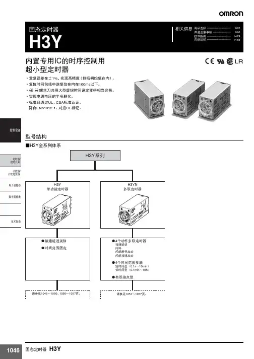
H3Y内置专用IC 的序控用超小型计时器•反复误差为±1%以及高楮密度(含初次数值)•复彊时间包括中途复归,在100ms以下。
•利用㊉㊀螺丝起子的大型指环时间设定容易。
•展现电源电压的半多元化功能。
•取得UL. CSA安全规格认证。
适合EMC规格(EN50081 -2、EN50082 -2)以VDE (TUV)0435/P2021为准。
可因应CE标志,◊整个H3 丫型系列动作方式复归方式限时动作/自行复归限时接点2C 4C供应电源B寸间截止亮灯显示农面安袈(嵌入端子)H3Y _2 型H3Y — 4 型表面安装(印刷电洛板专用端子)H3Y -2 一0型H3Y -4 一0 型注:H3Y型号并不含连按插坐及支抻金矚在内(另曽)。
H3YH3Y型式IBY -4 型H3Y -4 -0©电源电压AC IOO 、120V sasuACW- 2XJV5O«Hz DC 12V DC 24V DC 48 VDCIOO -II0V AC 100、120VACW- 2W50 60HzDC' 12V DC 24V DC 48 VDCIOO^llW0.5s◎◎———Is ◎◎ ◎ 05s o◎ ◎ ◎◎10s ◎ ◎◎ © ◎30s ◎ ◎◎ 0 ◎—60s ◎ ◎ ◎0 ◎—12Qs ◎ ◎—3min ◎ o◎ —5min ◎ o◎10m in ◎ ◎ ◎30min ◎ ◎©—60m in◎◎—3h◎注:AC 200〜230V 50,6GHz 观格可在容许电压变动范區内(AC 170〜253V )使用。
需要AC 240 50.60Hz (85〜110%)空式时,请洽询另一种方式°型式 H3Y —2 型 IBY -2-0®电源电压AC ICO ~ 120V AC 100 720V50WHJ!DC 12VDC24V DC 48 V ">、吨 豔® 從® DC 12VDC 24 VDC 48 V0.5s10s最大刻度时间20smsminUhninSOini n60min3hH3YH3Y a额定项目型式113Y-2(-0)型| H3Y-4G0)型电源电庄AC 100〜120V 50/60Hz • AC 200-230V 50/60Ilz DC 12V • DC 24V • DC d8V • DC100〜110V ♦容许电压变动范围电源电压的85~11O。
公司是欧姆龙一级代理商,价格优势明显,质量有保证,有大量库存,供货期短。
欢迎新老客户来电查询联系人:1 3 5 2 0 1 1 5 8 9 1 传0 1 0- 8 0 1 1 5 5 5 5转7 5 9 7 1 13F88L-RS173G3IV-PLKEB45P53G3JV-MANUAL3G3JZ-AB0223G3MV-A4075(YES)3G3MZ-A2004-ZV23G3MZ-A2007-ZV23G3MZ-A2015-ZV23G3MZ-A2055-ZV23G3RV-B418K-ZV13G3RV-B422K-ZV13G3RV-B4900-ZV13G3RX-A4220-Z43767-0010 MC374005-3066 UM5-3066C200H-ATT01C200H-BC101-V2C200H-CP114C200H-DA001C200H-DA002C200H-ID218C200H-ID501C200H-NC111C200H-OD501C200H-TS001C200HW-COM01C200HW-COM05-EV1C200HW-DRM21-V1C200HW-NC213C500-CE405CJ1W-OD263CP1W-20EDT1(Q)CP1W-40EDT1CPM1A-20EDT1CPM1A-40CDT-A-V1 CPM2A-20CDR-DCPM2A-20CDT-DCPM2A-30CDR-DCQM1-ID211CQM1-ME04RCQM1H-PLB21CRT1-AD04CS1D-CPU44SCS1H-CPU66HCS1H-CPU67HCS1W-BAT01CS1W-BI033CS1W-CN224CS1W-OC201CS1W-PDC55CS1W-SCU31-V1D4N-212GDRT1-232C2DRT2-AD04E2E-X10D1S DC12-24 2ME3X-DAC21-S 2ME5AZ-C3E5AZ-Q3E5AZ-R3E5CN-Q2HBT AC100-240 (Q)E5CN-R2HBT AC100-240 (Q)E5CN-R2T AC100-240 (Q)E5CZ-Q2 AC100-240E5CZ-R2MT AC100-240E5EZ-C3E6C2-CWZ6C 1024P/R 2M BY OMSG3JA-C425B AC100-240 FOR CHINA G3JA-C430B AC100-240 FOR CHINA G3JA-C437B AC100-240 FOR CHINA G3JA-D420B AC100-240 FOR CHINA G3JA-D425B AC100-240 FOR CHINA G3JA-D432B AC100-240 FOR CHINA G3JA-D451B AC100-240 FOR CHINA G3PB-535B-2N-VD DC12-24H5CN-XCN AC100-240H5F-BMKS2P DC12MKS3P-5 DC48MPT-CN550NS10-TV01B-V2R7A-CNB01S-ZR7A-CNB01SB-ZR7A-CNZ01C-ZR7D-AP04HR7D-AP08HR7D-BP01H-ZR7D-BP02H-ZR7D-BP02HH-ZR7D-BP04H-ZR7D-ZP01HR7D-ZP02HR7M-A40030-S1R7M-A75030-S1R7M-Z10030-S1ZR7M-Z20030-S1ZR88A-CNG01SB-ZR88D-GN01H-ML2-ZR88D-GN02H-ML2-ZR88D-GN04H-ML2-ZR88D-GN08H-ML2-ZR88D-GN10H-ML2-ZR88D-GN15H-ML2-ZR88D-GN20H-ML2-ZR88D-GN50H-ML2-ZR88D-GN75H-ML2-ZR88D-GT50H-ZR88D-GT75H-ZR88D-WN08H-ML2R88D-WN10H-ML2R88M-G10030H-BS2-Z R88M-G10030H-ZR88M-G1K020H-S2-Z R88M-G1K020H-ZR88M-G1K020T-BS2-Z R88M-G1K020T-S2-Z R88M-G1K020T-ZR88M-G1K030H-BS2-Z R88M-G1K030H-S2-Z R88M-G1K030H-ZR88M-G1K030T-S2-Z R88M-G1K520H-BS2-Z R88M-G1K520H-S2-Z R88M-G1K520H-ZR88M-G1K520T-BS2-Z R88M-G1K520T-S2-Z R88M-G1K520T-ZR88M-G1K530H-S2-Z R88M-G1K530T-S2-Z R88M-G20030H-BS2-Z R88M-G20030T-BS2-Z R88M-G20030T-S2-Z R88M-G2K010H-S2-Z R88M-G2K010H-ZR88M-G2K010T-S2-Z R88M-G2K010T-ZR88M-G2K020H-BS2-Z R88M-G2K020H-S2-Z R88M-G2K020H-ZR88M-G2K020T-S2-ZR88M-G2K030H-S2-Z R88M-G2K030T-S2-Z R88M-G3K010H-BS2-Z R88M-G3K010H-S2-Z R88M-G3K010H-ZR88M-G3K010T-S2-Z R88M-G3K020H-BS2-Z R88M-G3K020H-S2-Z R88M-G3K020H-ZR88M-G3K020T-S2-Z R88M-G3K020T-ZR88M-G3K030H-BS2-Z R88M-G3K030H-S2-Z R88M-G3K030H-ZR88M-G40030H-B-ZR88M-G40030H-BS2-Z R88M-G40030H-ZR88M-G40030T-BS2-Z R88M-G40030T-S2-Z R88M-G4K020H-BS2-Z R88M-G4K020H-S2-Z R88M-G4K020T-S2-Z R88M-G4K030H-BS2-Z R88M-G4K030H-S2-Z R88M-G4K510H-BS2-Z R88M-G4K510H-S2-Z R88M-G4K510T-S2-Z R88M-G5K020H-BS2-ZR88M-G5K030H-BS2-ZR88M-G5K030H-S2-ZR88M-G6K010H-BS2-ZR88M-G6K010H-S2-ZR88M-G75030H-BS2-ZR88M-G75030T-BS2-ZR88M-G75030T-S2-ZR88M-G7K515H-BS2-ZR88M-G7K515H-S2-ZR88M-G7K515T-S2-ZR88M-G90010T-S2-ZR88M-GP10030H-ZR88M-GP40030H-ZR88M-W10030T-S1SH-001-01MSH-001-03MSH-001-05MSH-001-10MV400-W23 3MV400-W24 3MWLCA32-41ZR-RX20A-CHROZR-RX40A-CHROZR-XRB1ZR-XRE1我公司是欧姆龙一级代理商,价格优势明显,质量有保证,有大量库存,供货期短。
OMRON时间继电器选型
接近开关是一种无需与运动部件进行机械直接接触而可以操作的位置开关,当物体接近开关的感应面到动作距离时,不需要机械接触及施加任何压力即可使开关动作,从而驱动直流电器或给计算机(plc)装置提供控制指令。
接近开关是种开关型传感器(即无触点开关),它既有行程开关、微动开关的特性,同时具有传感性能,且动作可靠,性能稳定,频率响应快,应用寿命长,抗干扰能力强等、并具有防水、防震、耐腐蚀等特点。
产品有电感式、电容式、霍尔式、交、直流型。
接近开关又称无触点接近开关,是理想的电子开关量传感器。
当金属检测体接近开关的感应区域,开关就能无接触,无压力、无火花、迅速发出电气指令,准确反应出运动机构的位置和行程,即使用于一般的行程控制,其定位精度、操作频率、使用寿命、安装调整的方便性和对恶劣环境的适用能力,是一般机械式行程开关所不能相比的。
它广泛地应用于机床、冶金、化工、轻纺和印刷等行业。
在自动控制系统中可作为限位、计数、定位控制和自动保护环节等。
OMRON时间继电器选型。
欧姆龙时间继电器选型
一、外形、装置方法、装置尺度
欧姆龙继电器的外形、装置方法、装置尺度品种许多,用户必须按整机的详细需求,提出详细的装置面积,答应继电器的高度、装置方法、装置尺度。
这是挑选继电器首先要思考的疑问。
以下几个疑问,选用时应予以注意:
(1).关于PC板式引出脚;脚距离大都为2.54×n(n=1、2、3……,以下同),如JZW5;也有2.5n,如JZG2-2/B;也有不符合规范距离的继电器,如MR72。
引出脚的长度通常为3.5。
(2).引出脚的可焊性、继电器的抗焊接热、引出脚相对底座的不笔直度等应有严厉的需求。
(3).快衔接式继电器;快衔接引出脚通常有250#(6.35×0.8)、187#(4.75×0.5)2种。
这类引出脚要特别注意插拔力需求,250#引出脚:拔力矩>10kg.cm;187#引出脚:拔力矩> 5kg.cm。
二、输入参量
不一样品种的输入参量,是挑选欧姆龙继电器类型的重要依据。
常见的输入参量的品种有:
(1).沟通输入参量。
当输入参量为沟通电压(电流)时,应选用沟通继电器。
选用这一类型的继电器,应注意以下几个疑问:沟通频率----沟通继电器输入电压(电流)的频率通常为50HZ,或60HZ。
因为二者线圈的感抗不一样,吸动电压有显着区别。
合同中应予注明。
环境温度----沟通继电器因为存在涡流损耗、磁滞损耗,继电器的温升较高,通常为70℃到80℃。
作业环境温度不宜过高,最佳为40℃到65℃,断定环境温度的计算公式:t1≤t2-t3-150C;注:t1:继电器最高环境温度,0C;t2:漆包线、绝缘材料最高答应长时间作业温度0C (B级为1300C;F级为1550C) t3:继电器均匀温升,0C。