使用说明书-防爆通球指示器
- 格式:doc
- 大小:370.00 KB
- 文档页数:5
BTQ—02B带压拆卸型通球指示器目录一、概述…………………………………………………1二、技术特性……………………………………………2三、设备结构……………………………………………3四、安装使用…………………………………………5五、钟控头的调整 (7)1、钟控表头技术特性 (7)2、钟控表头操作方法 (7)3、外接远传信号的引线方法 (9)六、带压拆卸方法 (10)七、装箱单 (12)一、概述清管器通球指示器是长输管线通球除垢工艺流程中的必需设备;它可以准确的显示出清管器是否已通过了某一个预定地点,辅助清管扫线的顺利完成。
就目前来看,国内外所采用的通球指示器基本可满足清管扫线的要求,但对其维护、维修就比较麻烦,大多数需要管线卸压停产,经济损失不可估量。
基于上述原因,本公司又开发、研制了无需管线卸压停产即可带压拆卸型通球指示器BTQ-02B,其主体部件由不锈钢制成,耐酸碱、耐腐蚀。
BTQ-02B型通球指示器属于机械接触形式,动作灵敏、可靠。
它可以在管线上通过机械结构定位、定时地传递出管线内清管器类物体的通过情况,具有结构简单、防爆、指示直观可靠且可带压拆卸等诸多优点。
本说明书对您安装使用和妥善保养BTQ-02B型指示器是有所帮助的。
所以在安装使用本指示器前,请您仔细阅读说明书。
二、技术特性1、适用压力范围: P ≤ 10Mpa ;2、适用温区范围: -20℃~80℃;3、适用管径:D≥DN100;4、适用介质:石油产品,天然气及其它非腐蚀性流体。
管线材质为与20钢焊接性能良好的各类金属管线。
5、摆针伸入管内的长度为60 mm。
6、显示方式A :现场指示旗;手动复位B:现场数码显示;LED数码显示通球时间并保存C:远传信号端子(SPDT);容量:AC380 DC220 5A7、设备在正常使用条件下安装高度约为1.1米;8、适用于防爆的场所安装;9、防爆标志防护等级防腐等级dⅡBT4 IP65 WF1 适用范围:爆炸性气体混合物危险场所:1区、2区爆炸性气体混合物:ⅡA、ⅡB温度组别:T1-T4(2)10、型号表示方法:B T Q-02B技术编号(带压拆卸)通球防爆型三、设备结构BTQ-02B型指示器主要由以下几种部件组成见图1)。
浙制00000690号XK3150-Exd防爆型称重仪表使用说明书宁波朗科精工技术有限公司注意事项由宁波朗科精工技术有限公司生产的XK3150-Exd型防爆型称重仪表国家级仪器仪表防爆安全监督检验站(NEPSI)检验,符合GB3836.1-2010、GB3836.2-2010、GB3836.4-2010和GB3836.20-2010标准的有关要求,其防爆标志为Ex d [ia Ga]ⅡB T6 Gb,防爆合格证号为GYB12.1139X。
本次认可的产品使用应遵循下列事项如下:1、产品防爆合格证号后缀“X”代表产品使用有特殊要求:涉及隔爆接合面的维修须联系产品制造商。
2、产品安全栅本安端参数:YB958H安全栅:U0=7.5V; I0=560mA ; P0=1.1W; C0=11μF; L0=70μH。
YB964H安全栅:U0=12V; I0=12mA ; P0=38mW; C0=1.0μF; L0=160mH。
3、产品使用环境温度:-10℃~+40℃。
4、产品隔爆部件现场使用应遵守“严禁带电开盖”的原则。
5、电缆引入口必须配用经防爆检验认可、具有防爆等级为Ex dⅡB、螺纹规格为G1/2的电缆引入装置, 与壳体构成的隔爆螺纹接合面啮合扣数应不小于5扣。
同时,电缆引入装置的使用必须符合其使用说明书的要求。
6、产品外壳设有接地端子,用户在安装使用时应可靠接地。
7、用户不得自行更换该产品的零部件,应会同产品制造商共同解决运行中出现的故障,以杜绝损坏现象的发生。
8、用户在安装、使用和维护本产品时须同时遵守产品使用说明书、GB3836.13-1997“爆炸性气体环境用电气设备第13部分:爆炸性气体环境用电气设备的检修”、GB3836.15-2000“爆炸性气体环境用电气设备第15部分:危险场所电气安装(煤矿除外)”、GB3836.16-2006“爆炸性气体环境用电气设备第16部分:电气装置的检查和维护(煤矿除外)”和GB50257-1996“电气装置安装工程爆炸和火灾危险环境电力装置施工及验收规范”和的有关规定。
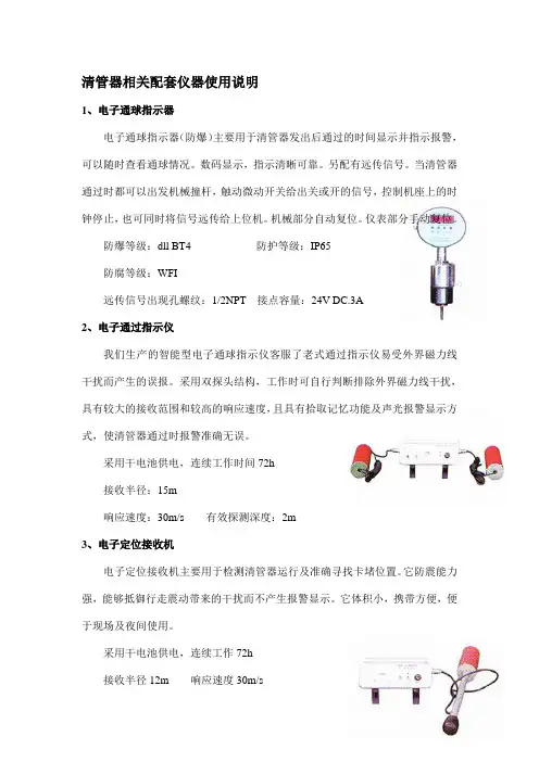
清管器相关配套仪器使用说明1、电子通球指示器电子通球指示器(防爆)主要用于清管器发出后通过的时间显示并指示报警,可以随时查看通球情况。
数码显示,指示清晰可靠。
另配有远传信号。
当清管器通过时都可以出发机械撞杆,触动微动开关给出关或开的信号,控制机座上的时钟停止,也可同时将信号远传给上位机。
机械部分自动复位。
仪表部分手动复位。
防爆等级:dll BT4 防护等级:IP65防腐等级:WFI远传信号出现孔螺纹:1/2NPT 接点容量:24V DC.3A2、电子通过指示仪我们生产的智能型电子通球指示仪客服了老式通过指示仪易受外界磁力线干扰而产生的误报。
采用双探头结构,工作时可自行判断排除外界磁力线干扰,具有较大的接收范围和较高的响应速度,且具有拾取记忆功能及声光报警显示方式,使清管器通过时报警准确无误。
采用干电池供电,连续工作时间72h接收半径:15m响应速度:30m/s 有效探测深度:2m3、电子定位接收机电子定位接收机主要用于检测清管器运行及准确寻找卡堵位置。
它防震能力强,能够抵御行走震动带来的干扰而不产生报警显示。
它体积小,携带方便,便于现场及夜间使用。
采用干电池供电,连续工作72h接收半径12m 响应速度30m/s有效探测深度:8m 定位精度:±7cm4、清管器电池充电器本充电器采用电压保护,当清管器锂电池充满电后,电压达到保护值,无须人员值守,充电器自动断电。
(注:额定充电电压为220v)专用充电机充电本公司生产的清管器及配套仪器均采用可充电镍镉电池供电。
使用前必须对仪器进行充电,充电后方可投入使用。
充电步骤如下:对清管器进行充电,将充电机红色夹头夹在清管器后面的铜电极柱上,黑色夹头夹在清管器后面的铁电极柱上,插上充电机电源插头(220v),一、清管器工作流程说明:1、正常流量:管输介质由首站经阀门2进入主管线(阀门1、3关闭状态),经阀门5进入末站。
2、清管发球流程:检查阀门1、阀门3是否关闭,打开快开盲板,将清管器推入发射筒变径处,顶紧,关闭盲板,打开阀门3。
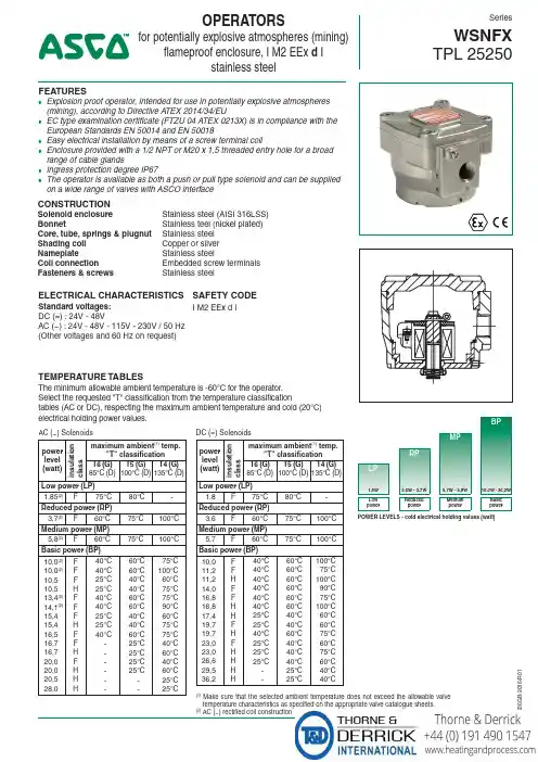
All leaflets are available on: www.asconumatics.euPIC-8-26-GB80226G B -2016/R 01OPERATORSfor potentially explosive atmospheres (mining)flameproof enclosure, I M2 EEx d Istainless steelSeriesWSNFX TPL 25250FEATURES●Explosion proof operator, intended for use in potentially explosive atmospheres (mining), according to Directive A TEX 2014/34/EU●EC type examination certificate (FTZU 04 ATEX 0213X) is in compliance with the European Standards EN 50014 and EN 50018● Easy electrical installation by means of a screw terminal coil●Enclosure provided with a 1/2 NPT or M20 x 1,5 threaded entry hole for a broad range of cable glands● Ingress protection degree IP67●The operator is available as both a push or pull type solenoid and can be supplied on a wide range of valves with ASCO interfaceCONSTRUCTIONSolenoid enclosure Stainless steel (AISI 316LSS)BonnetStainless teel (nickel plated)Core, tube, springs & plugnut Stainless steel Shading coil Copper or silver NameplateStainless steelCoil connection Embedded screw terminals Fasteners & screwsStainless steelTEMPERATURE TABLES(1)Make sure that the selected ambient temperature does not exceed the allowable valve temperature characteristics as specified on the appropriate valve catalogue sheets.(2)AC (~) rectified coil constructionStandard voltages:DC (=) : 24V - 48VAC (~) : 24V - 48V - 115V - 230V / 50 Hz (Other voltages and 60 Hz on request)ELECTRICAL CHARACTERISTICS I M2 EEx d I SAFETY CODEThe minimum allowable ambient temperature is -60°C for the operator. Select the requested "T" classification from the temperature classificationtables (AC or DC), respecting the maximum ambient temperature and cold (20°C) electrical holding power values.AC (~) Solenoidspower level (watt)i n s u l a t i o n c l a s smaximum ambient (1) temp."T" classificationT6 (G)85°C (D)T5 (G)100°C (D)T4 (G)135°C (D)Low power (LP)1,85(2)F75°C80°C -Reduced power (RP)3,7(2)F 60°C 75°C 100°C Medium power (MP)5,8(2)F 60°C 75°C 100°C Basic power (BP)10,0(2)10,0(2)10,510,513,4(2)14,1(2)15,415,416,516,716,720,020,020,528,0F F F H F F F H F F H F H H H40°C 40°C 25°C 25°C 40°C 40°C 25°C 25°C 40°C ------60°C 60°C 40°C 40°C 60°C 60°C 40°C 40°C 60°C 25°C 25°C 25°C 25°C --75°C 100°C 60°C 75°C 75°C 90°C 60°C 75°C 75°C 40°C 60°C 40°C 60°C 25°C 25°CDC (=) Solenoids power level (watt)i n s u l a t i o n c l a s smaximum ambient (1) temp."T" classificationT6 (G)85°C (D)T5 (G)100°C (D)T4 (G)135°C (D)Low power (LP)1,8F75°C80°C -Reduced power (RP)3,6F 60°C 75°C 100°C Medium power (MP)5,7F 60°C 75°C 100°C Basic power (BP)10,011,211,214,016,816,817,419,719,723,023,026,629,536,2FFHFFHHF H F H H H H 40°C 40°C 40°C 40°C 40°C 40°C 25°C 25°C 40°C 25°C 25°C 25°C --60°C 60°C 60°C 60°C 60°C 60°C 40°C 40°C 60°C 40°C 40°C 40°C 25°C 25°C100°C 75°C 100°C 90°C 75°C 100°C 60°C 60°C 75°C 60°C 75°C 60°C 40°C 40°CBPMPRPLP1,8W 3,6W - 3,7W 5,7W - 5,8W 10,0W - 36,2WLow powerReduced powerMedium powerBasic powerPOWER LEVELS - cold electrical holding values (watt)All leaflets are available on: www.asconumatics.eu 8-26-2P I C -08-0026-G B -- A v a i l a b i l i t y , d e s i g n a n d s p e c i fic a t i o n s a r e s u b j e c t t o c h a n g e w i t h o u t n o t i c e . A l l r i g h t s r e s e r v e d .80226G B -2016/R 01SERIES WSNFXprefix weight PRODUCT SELECTION GUIDE(The selection can only be made in conjunction with the appropriate valve catalogue sheet)STEP 1Select basic valve catalogue number, including pipe thread indentificationletter from one of the specification tables on the separate catalogue pages.Example: 8327B002STEP 2Select voltage. Refer to standard voltages on page 1.Example: 230V / 50HzSTEP 3Select solenoid prefix (combination). Refer to the prefix table on this page and respect the indicated power level and cold electrical holding values mentioned on page 1.NOTE: Make sure that the ambient temperature does not exceed the allowable valve temperature characteristics.Example: WSNFX 75°C ambient Basic Power (BP) 10W I M2 EEx d I STEP 4Final catalogue / ordering number.Example:WSNFX 8327B002 230V / 50 Hz TPL 25250MOUNTING BRACKETBracket kit no.: C139824contains: Stainless steel 304 SS screws and bracketDIMENSIONS (mm), WEIGHT (kg)2,7 kg●Special moulded-in solid state components for peak voltage suppression and/or AC (~) rectificationADDITIONAL OPTIONSINSTALLATION● Multi language installation/maintenance instructions are included with each valve ● The solenoid operators can be mounted in any position without affecting operation● Any certified flameproof cable entry device for potentially explosive atmospheres (mining) can be fitted in the 1/2" NPT (M20 x 1,5 as an option) threaded entry hole, refer to the nameplate for identification of the maximum cable temperature ● Internal and external earthing connection●The operator can be rotated 360° to select the most favourable position for cable entryWSNFXPREFIX TABLEprefixdescriptionpower level 1234567LP RP MP BP E TThreaded conduit/hole (M20 x 1,5)●●●●W S N FFlameproof - 316 SS (EN/IEC 60079-1, 61241-1)*●●●●X Other special constructions●●●●● Available feature* ATEX solenoids are also approved according to EN 13463-1 (non electrical valves)ORDERING EXAMPLES / VALVES:WSNFX 8327B001230V /50 Hz WSNFETX G 327B001MS 230V /50 Hz WSNFX B 320A184E 24V /DC WSNFX B 316A054V 230V /50Hz WSNFETXB316B076CO 240V /60 Hzprefix pipe thread voltage basic numbersuffix。
QB 12.5B ~400B隔爆型阀门电动装置使 用 说 明 书OPERATION INSTRUCTION MANUALFORFLAMEPROOF TYPE ELECTRIC V ALVEACTUATORS中华人民共和国常州电站辅机总厂有限公司CHANGZHOU POWER STATION AUXILIARY EQUIPMENT WORKS,Ltd.THE PEOPLE ’S REPUBLIC OF CHINA1.概述General Description首先感谢您选用我厂生产的QB12.5B~400B系列隔爆型阀门电动装置及其它产品。
我厂是机械工业部定点制造各种阀门电动装置及其专用电机的厂家,于1995年通过ISO9001质量认证。
QB系列隔爆型是我厂广泛地吸取国内外阀门控制的先进经验而设计的新一代产品。
具有结构紧凑、性能可靠、调整方便等特点。
隔爆性能符合GB3836.1-2000《爆炸性环境用防爆电气设备通用要求》、GB3836.2-2000《爆炸性环境用防爆电气设备隔爆型电气设备“d”》及JB/T8529-1997《隔爆型阀门电动装置技术条件》的规定。
First and foremost, thank you for your choice of our QB12.5B~400B Series flame-proof electric valve actuators and other products. Our works is appointed by the Machine Building Industry Ministry to manufacture various electric valve actuators and their special purpose motors and our quality system was certified to conform to ISO 9001 in 1995. These products are a new generation developed by us. Adopting advanced valve control technology at home and abroad, these products are of compact structure, reliable performance and easy adjustment. Flameproof performance of these products conforms to Std GB3836.1-2000 ELECRICAL APPARATUS FOR EXPLOSIVE A TMOSPHERS-GENRAL REQUIREMENTS and Std GB3836.2-2000 ELECTRICAL APPARA TUS FOR EXPLOSIVE ATMOSPHERES-FLAMERPROOF ELECTRICAL APPARATUS“d”and Std JB/T 8529-1997 TECHNICAL SPECIFICATIONS OF FLAMEPROOF ELECTRIC V ALVE ACTUATORS.2.型号表示方法Type Representation2.1防爆类型:隔爆型Explosion-proof type: flame-proof输出转速:r/min Output speed: r/min额定转矩10N·m Nominal torque of output shaft 10N·mQ表示部分回转型阀门电动装置,适用于球阀、蝶阀等。
防爆机械式通球指示仪沈阳鑫联石化设备有限公司沈阳鑫联石化设备有限公司目录一、前言二、技术特性三、设备须知3.1设备结构3.1装箱单四、安装程序五、钟控头的调整与使用六、远传信号的连接七、附件:基座安装特别提示沈阳鑫联石化设备有限公司一、前言清管器通过指示仪是长输管线通球除垢工艺流程中的必需设备;其中BTQ-002型指示仪亦属于机械接触式的指示器,它是在XLTQ-002型的基础上改造而成的。
具有结构简单,防爆,指示直观可靠等许多优点。
它可以在管线上通过机械定位、定时地传递出管线内清管器类物体的通过情况,然后通过电、光或特制时钟等二级信号源给操作者提供信息,指导流程的倒换。
本说明书对您安装使用和妥善保养BTQ-002型指示仪是有所帮助的。
所以在安装使用本指示仪前,请您仔细阅读说明书。
本说明书由沈阳鑫联石化设备有限公司机械室编制,并负责解答您对本设备的有关咨询。
二、BTQ—002型防爆机械式通球指示仪的技术特性1、使用压力10Mpa(100Kg/cm2)使用温度: -40℃~100℃;2、要求所安装管线的管径D≥DN100,输送介质为石油产品,天然气及其它非腐蚀性流体。
管线材质为与20钢焊接性能良好的各类金属管线。
3、摆针伸入管内的长度为60 mm。
沈阳鑫联石化设备有限公司4、管线内正、反两个方向通过清管器时指示仪可正常显示。
5、设备在正常使用条件下安装高度为325mm。
6、钟控指示器采用电子钟芯体,4节5号干式电池为电源,扳机摆动≥75°左右时,时钟闪烁显示清管器通过的时间,还可以在显示表的侧面防爆接口连线,输出一个脉冲式开关信号到控制室。
7、适用于防爆的场所;8、出厂前经过密封检验;9、设备总重为4.85Kg;10、防爆标志防护等级防腐等级dⅡBT4 IP65 WF111、型号表示方法:B T Q-002技术编号通球防爆型适用范围:爆炸性气体混合物危险场所:1区、2区爆炸性气体混合物:ⅡA、ⅡB沈阳鑫联石化设备有限公司温度组别:T1-T4三、设备须知3.1设备结构(参考图1)BTQ-002型指示仪主要由机械主体及钟控头二大部件组成。
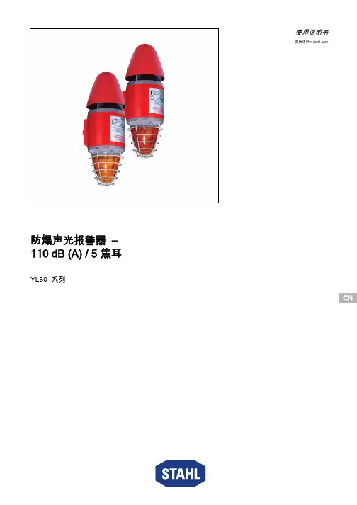
CN CN CN CN CN CN CN CN CN CN CN CN CN CN CN CN CN CN CN CN CN CN CN CNCN使用说明书其他语种 防爆声光报警器 – 110 dB (A) / 5 焦耳YL60 系列总体信息2防爆声光报警器 – 110 dB (A) / 5 焦耳YL60 系列内容目录1总体信息 ..............................................................................................................21.1制造商 .................................................................................................................21.2本使用说明书信息 ...............................................................................................31.3其他文件 ..............................................................................................................31.4标准和规定的符合性声明 ....................................................................................32图标说明 ..............................................................................................................32.1操作指南中的图标 ...............................................................................................32.2警告提示 ..............................................................................................................42.3设备上的图标 ......................................................................................................53安全说明 ..............................................................................................................53.1操作指南的保管 ...................................................................................................53.2安全使用 ..............................................................................................................53.3改装和改动 ..........................................................................................................54功能与设备结构 ...................................................................................................64.1功能 .....................................................................................................................65技术数据 ..............................................................................................................76仓储和运输 ..........................................................................................................97装配和安装 ........................................................................................................107.1尺寸信息/固定尺寸 ..........................................................................................107.2安装/拆卸、使用位置 .......................................................................................117.3安装 ...................................................................................................................218调试 ...................................................................................................................219运行 ...................................................................................................................229.1故障排除 ............................................................................................................2210保养、维护、修理 .............................................................................................2210.1保养 ...................................................................................................................2310.2修理 ...................................................................................................................2310.3退回 ...................................................................................................................2411清洁 ...................................................................................................................2412弃置处理 (2413)配件和备件 (24)1总体信息1.1制造商R. STAHL Schaltgeräte GmbH 照明和信号业务部门Nordstr. 1099427 Weimar 德国R. STAHL Schaltgeräte GmbH Am Bahnhof 3074638 Waldenburg 德国电话:传真网站:电子邮箱:+49 3643 4324+49 3643 ****************电话:传真网站:电子邮箱:+49 7942 943-0+49 7942 ****************282525 / YL6060300170 2018-04-13·BA00·III·zh·01图标说明3CNCNCNCNCNCNCNCNCN防爆声光报警器 – 110 dB (A) / 5 焦耳YL60 系列1.2本使用说明书信息ID编号:282525 / YL6060300170出版代码:2018-04-13·BA00·III·zh·01原版操作指南是英文版。

FeaturesRobust corrosion proof 316L stainless steel enclosureEpoxy powder coat paint finishAlternative housing colours are available to meet specific requirementsIngress protection IP66Single or double switchOptional equipment tags and duty labelsOptional stainless steel lift flap2 × 316 Stainless steel stopping plugs included3 x M20 cable entriesStainless steel fastenersTest key facilityBreak glass hammer accessory availableDNV type approved IEC 60945 & DNVGL-CG-0339 Appro valsIECEx certificate: IECEx ULD 15.0018XATEX certificate: DEMKO 15 ATEX 1589XTR-CU Ex EAC certificate: RU C-GB.AA71.B.00109PESO CCOE certified: P471509INMETRO IEx 20.0051XSIL 2 compliant to IEC 61508 (2010)Co dingEx db IIC T6 Gb Ta. -55°C to +70°C (Single switch)Ex db IIC T5 Gb Ta. -55°C to +70°C (Dual switch)Ex db IIC T6 Gb Ta. -55°C to +60°C (Dual switch)Specificatio nSTExCP8-BG:Version: Break Glass Manual Call Point Coding:Ex db IIC T6 Gb Ta. -55°C to +70°C (Single switch)Ex db IIC T5 Gb Ta. -55°C to +70°C (Dual switch)Ex db IIC T6 Gb Ta. -55°C to +60°C (Dual switch) Ingress protection:EN/IEC 60529 – IP66Enclosure matl:316L Stainless SteelColour:RAL3000 Red (others available on request) Cable entries: 2 x M20x1.5 top and1 x M20x1.5 side.Back box can be rotated to give2 x bottom and 1 x side entriesStopping plugs: 2 × 316 Stainless Steel plugs as standardBrass and Nickel plated plugs optional Terminals:DIN rail 8 × 2.5mm² SAK2.5 orTermination board featuring 6 × 2.5mm² terminalsplus 4 x dedicated EOL & Series terminals Earth:External M5 earth connectionRelative Humidity:R.H. 95% @ 20°CTest:Test key facilityWeight: 4.2Kg/9.26IbsVoltage Range:Max inputCurrent:Limitations for EOL / Series Resistors:250Vac Max 5.0A max not permitted48Vdc Max 1.0A max min. 2.2kOhm24Vdc Max 3.0A max min. 470 OhmEOL and Series Diode Values:xxx:Zener Value Max. current supply permitted 3V3 3.3V Diode230mA4V7 4.7V Diode162mA5V1 5.1V Diode149mA5V6 5.6V Diode136mA6V2 6.2V Diode122mA6V8 6.8V Diode112mA10V10V Diode76mA12V12V Diode63mA Part Co desVer si on:Par tr efer en ce:Descr i p ti on:Product type:STExCP8BG Break Glass Manual Call PointSwitch Type: [s]SDSPCO/SPDTDPCO/DPDTTerminals: [t]DPDIN Rail 8 × SAK2.5Termination board: 6 × 2.5mm² terminals plus 4 ×EOL & Series terminalsLift flap: [l]LNLift flapNo lift flapCable Entry Type:[e]ABCDEFG3 x M20x1.5mm2 × 1/2" NPT – adaptors2 × 3/4" NPT – adaptors2 x M25x1.5mm – adaptors1 × 1/2" NPT – adaptor1 × 3/4" NPT – adaptor1 x M25x1.5mm – adaptorStopping plugmaterial: [m]S Stainless SteelDuty label /Equipment tag:[d]:1234567No Duty label, no Equip. tagDuty label Stainless SteelDuty label St/St + Equip. tagDuty label Metalised PolyesterDuty label M. Poly. + Equip. tagEquip. tag onlySpecial label requirementProduct version:[v]A1IECEx, ATEX, Ex EAC, PESO & DNV approvedEnclosure colour:[x]RBNYVSKMZRedBlueGreenYellowRed/WhiteYellow/BlackBlackMagentaRed/BlackDefault variable:[u]N Default = N – not currently usedE.O.L.Module: [e]optionalExxxRED1ExxxZResistor value in Ohms e.g. E470R = 470 OhmDiode IN4007 = ED1Zener diode e.g. E5V1Z = 5.1VSeries Module: [s]optionalSxxxRSD1SxxxZResistor value in Ohms e.g. S1K5R = 1.5K OhmDiode IN4007 = SD1Zener diode e.g. S5V1Z = 5.1VSpares:SP70-0001SP70-0040Replacement break glass elements (Pack of 50)STxCP8-BG Test KeyAccessories:SP65-0001-A2SP65-0001-A4SP65-0002-A2SP65-0002-A4SP70-0065Pole Mount Bracket Kit 2" St/St A2 (304)Pole Mount Bracket Kit 2" St/St A4 (316)Sunshade – St/St A2 (304)Sunshade – St/St A4 (316)Break glass hammer with chainE2S Warning S ignals s ales @ No liability is accepted for any consequence of the use of this document. The technical specification of this unit is subject to chang e without notice due to our policy of continual product development. All dimensions are approximate. This unit is sold subject to our standard conditions of sale, a copy of which is available on request.3 Ju n 2020。

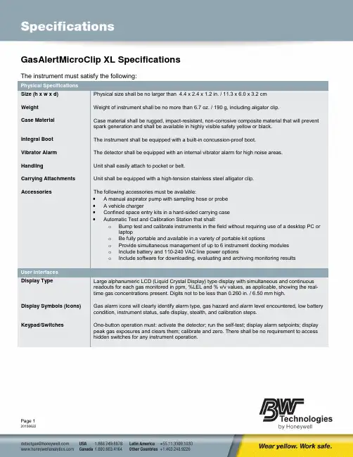
GasAlertMicroClip XL SpecificationsThe instrument must satisfy the following:Physical SpecificationsSize (h x w x d) Physical size shall be no larger than 4.4 x 2.4 x 1.2 in. / 11.3 x 6.0 x 3.2 cmWeight Weight of instrument shall be no more than 6.7 oz. / 190 g, including aligator clip.Case Material Case material shall be rugged, impact-resistant, non-corrosive composite material that will preventspark generation and shall be available in highly visible safety yellow or black.Integral Boot The instrument shall be equipped with a built-in concussion-proof boot.Vibrator Alarm The detector shall be equipped with an internal vibrator alarm for high noise areas.Handling Unit shall easily attach to pocket or belt.Carrying Attachments Unit shall be equipped with a high-tension stainless steel alligator clip.Accessories The following accessories must be available:• A manual aspirator pump with sampling hose or probe• A vehicle charger•Confined space entry kits in a hard-sided carrying case•Automatic Test and Calibration Station that shall:o Bump test and calibrate instruments in the field without requiring use of a desktop PC orlaptopo Be fully portable and available in a variety of portable kit optionso Provide simultaneous management of up to 6 instrument docking moduleso Include battery and 110-240 VAC line power optionso Include software for downloading, evaluating and archiving monitoring resultsUser InterfacesDisplay Type Large alphanumeric LCD (Liquid Crystal Display) type display with simultaneous and continuousreadouts for each gas monitored in ppm, %LEL and % v/v values, as applicable, showing the real-time gas concentrations present.Digits not to be less than 0.260 in. / 6.50 mm high.Display Symbols (Icons) Gas alarm icons will clearly identify alarm type, gas hazard and alarm level encountered, low battery condition, instrument status, safe display, stealth, and calibration steps.Keypad/Switches One-button operation must: activate the detector; run the self-test; display alarm setpoints; displaypeak gas exposures and clears them; calibrate and zero. There shall be no requirement to accesshidden switches for any instrument operation.Monitoring CapabilityConfigurations The gas detector must be available in 1, 2, 3, or 4 gas models that continuously and simultaneously monitor for oxygen, combustible/methane gases, hydrogen sulfide, carbon monoxide as applicable.Gases Detected and Measuring Specifications Gases Standard Measuring Range In Increments of: Hydrogen Sulfide 0-100 ppm H2S 1 ppm Carbon Monoxide 0-500 ppm CO 1 ppm Oxygen 0-30.0 % O20.1 % Methane 0-5% v/v methane 0.1% methane Combustible gases 0-100% LEL 1.0% LELSensor Type Sensors must be plug-in.Longer Life The catalytic (combustible/methane) sensor should not be affected by common sulfur compounds, such as H2S.Instrument PowerBattery Type and Run Time Lithium-polymer rechargeable battery pack. The run time of a new instrument shall not be less than 18 hours at room temperature. The run time shall not be less than 12 hours at any time over 2 years of use in a temperature range between -4°F to +122°F (-20°C to +50°C)Rechargeable Choices A Vac (110 to 240) line charger, 12 Vdc (vehicle) charger and 12 Vdc / 24 Vdc cable must beavailable.Charge Time Typical charge time for rechargeable batteries shall not be more than 6 hours per battery.EnvironmentalTemperature Range Normal operation: -4 to +122 °F / -20 to +50 °CHumidity 0-95% RH (non-condensing) continuousIngress Protection IP 68CalibrationAutomatic Calibration Calibration must be fully automatic with Auto Zero and Auto Span functions. Instrument must advise as each automatic function takes place and when to apply gas. Calibration span levels must be “UserSettable”.Calibration Diagnostics Equipped with calibration diagnostics protection that ensures a valid calibration, the detector mustcheck the ambient air and the calibration gas. If either does not meet expected values, the detectorwill refuse calibration and automatically exit the procedure, retaining all previous values.Basic Operational FeaturesInstrument Activation One-button activation. ON function must:•Test the battery and advise condition•Display the current alarm set points•Provide a full function self-test of sensor integrity, circuitry integrity and alarm activation•Automatically calibrate the oxygen sensor•Automatically zero H2S, CO and LEL sensors•Advise when the next calibration is due in days, or advise the number of days overdueInadvertent Shut-off Unit must not be able to be turned OFF accidentally and will incorporate a timed off function thatprovides audible/visual/vibration OFF indications.Peak Exposures Records peak (maximum) exposure to gases encountered and must display the reading on demand.Accumulated Exposures Records both TWA (time-weighted average) to toxic gases based on an 8-hour workday and STEL(short-term exposure limit) to toxic gases based on a 5-15 minute user-selectable work period.(STEL period is adjustable.) Must display readings on demand.Confidence Beep Confidence beep must be a user selectable option.IntelliFlash (ComplianceIntelliFlash verifies operation and compliance to both the user and supervisor.Flash)Instrument Status Advise The detector must constantly analyze and test its own operational status and provide alarm advice of any malfunction.Backlight Backlight automatically illuminates the display in all alarm conditions (auto with time-out) and can be reactivated on demand with a button press.Adjustable Options The unit shall be equipped with user options for the following functions:•Adjust STEL period (5-15 minutes in 1 minute intervals)•Set calibration span levels and due date•Toggle ON/OFF: confidence beep, oxygen auto-calibration at start-up, Auto-zero LEL, CO andH2S on start-up, latching alarms, “SAFE” display function (does not display gas concentrationsunless readings change), stealth mode for silent operations, Force calibration when calibrationoverdue, Calibration lockout: calibration must be invoked via IR, mandatory bump test option,bump test reminder•Multi-language LCD selection in English, French, German, Portuguese and Spanish•Select combustible gases measurement: 0-100% LEL (Lower Explosive Limit) or Methane gas 0-5.0% v/v•Alarm setpoint disable (set to zero for off).•Calibration due date (1 to 365 days, or set to zero for off)•User-settable confidence beep•Individual sensor enable/disable.Auto Zero Protection Must be able to activate Auto Zero at any time. To ensure a valid Auto Zero, the instrument will firsttest the ambient air for background interfering gas before proceeding with the Auto Zero function.Instrument AlarmsAlarms and Type Simultaneous visual display alarms, audible alarms and vibrator alarms must warn in the event of agas alarm condition, sensor fault or instrument status alarm.Number of Gas Alarms Must be equipped with four (4) user-settable alarm levels, including instant low, instant high, TWA(Time- weighted average) and STEL (short-term exposure limit). Also, will include an OL (over limit)alarm.Visual Alarms Instrument must be equipped with at least three flashing alarm bars easily visible from multipleangles. The backlight must light in all alarm conditions. LCD must provide positive clear alarm adviceas to which alarm level and type has been exceeded (instant LOW, instant HIGH, TWA, STEL and/orover limit).Audible Alarm Instrument must be equipped with one variable pulsed audible alarm that shall be rated at 95+ dB. Vibrator Alarm Instrument must be equipped with an internal vibrator alarm for high noise areas.Alarm Set points Alarm set points must be adjustable. The current alarm set points shall be displayed each time onstart-up.Over Limit Exposure Protection For exposures above the instrument’s measuring range for the combustible sensor, the instrument will provide an over limit latching alarm that must be acknowledged.Low Battery Warning Must be equipped with low battery audible and visual alarms.DataloggingRecorded All events and occurrences.Data Storage Period With a default 15-second sampling rate interval the storage capacity will be 16 hours. Compatibility Data must be compatible for use with standard office programs, such as Excel and Access.Event LoggingRecorded Must record the last 10 alarm events encountered. Information shall include: gas monitored, alarm level (in ppm or %) encountered, alarm duration in minutes and seconds, time elapsed since eachalarm event occurred, life remaining, and cumulative alarm time.Certifications and ApprovalsIntrinsic Safety Instrument must be certified by the following standards:•Approved by CSA to both U.S. and Canadian StandardsCAN/CSA C22.2 No. 157 and C22.2 152ANSI/UL - 913 and ANSI/ISA - 12.13.01 Part 1CSA Class I, Division 1, Group A, B, C, and D•ATEX: CE 0539 g II 1 G Ex ia IIC T4 GaSira 13ATEX2330EN 60079-0, EN 60079-11, and EN 60079-26•IECEx: Ex ia IIC T4 Ga IECEx CSA 05.0015IEC 60079-0, IEC 60079-11, IEC 60079-26•KTL 12-KB4BO-0659X•EAC Certificate: RU С-GВ.ГБО5.В.01115Manufacturing Approval The instrument must be certified compliant with ISO 9001 provisions.RFI/EMI Protection RFI/EMI protection must comply with EMC directive 2004/108/ECWarrantyWarranty Two-year full, non-prorated warranty including instrument, sensors and battery.Battery is guaranteed to have 12 hour runtime during warranty period under normal operating temperature of 4°F / -20°C to 122°F / 50°C.。
FBQ-2防爆球
使
用
说
明
书
北京斯达恒通科技有限公司
-----------------------
中国*北京
产品名称:FBQ-2防爆球
产品品牌:斯达恒通
参数指标:
1.外径840mm,
2.防爆球口径600mm。
可以装入450*350mm的物体
3.外形尺寸:1050*840*1170mm。
4.重量:398kg。
5.抗爆当量:2kg(TNT)。
6.遥控距离:大于20m。
产品特点:
1.防护性能好,抗爆能力强:完全密闭的结构可有效防护人员的人身安全,抗爆当量2公斤TNT。
2.排爆完全,无需人员近距离操作:开启球盖采用无线遥控+远距离有线操控+手把摇动。
控制距离大于20米。
《北京斯达恒通科技有限公司》
主营产品:环境安全检测仪器、消防救护破拆装备、应急救援器材、食品安全检测仪器、通风测绘仪表、粉尘测量及效验仪器、堵漏器材、安防安检防护器材等,已广泛应用于煤矿、救护队、石油化工、学校、实验室、建筑、交通、民航、物流、政府机构,以及各种厂矿企业。
YY-TZS-Ⅱ防爆机械式通球指示器使用说明书沈阳仪表科学研究院使用说明书防爆机械通球指示器是防爆场所管线清管、除垢工艺流程中的必备设备,它集中了各家通过指示器的优点,增加了自己的特色功能,具有指示直观、性能稳定、使用方便等诸多优点,为用户提供了更加满意的服务。
一、产品组成框图:电源开关远传显示模块时钟模块触发机构控制时间预设机械式传动器产品框图二、产品特点:(1)该产品为最小组成的基本型,可独立工作完成通球指示的基本功能。
(2)产品工作时,内置计时器,自动走时,可以显示标准时间(智能控制、数码显示)。
(3)本产品供电电压DC6V。
(4)可远传控制信号。
(5)远传控制接点容量:24VDC、2A。
(6)远传控制信号作用时间:5S。
三、适用范围:(1)爆炸性气体、易燃介质场所。
(2)防爆标志dⅡBT4/IP55。
四、使用方法:( 1 ) 连接好设备引出的两条远传信号线,确认无误后,拧开电池仓盖,按图中所示极性放入两节CR123A电池后拧紧电池仓盖,设备即上电开始工作。
电池仓CR123A CR123A+ - + -( 2 ) 前面板的显示窗此时显示的是,未经设定的时间:“00 :00”,工作前需设定时间,中间的两个红色发光二极管表示时钟的“秒”工作信号。
( 3 ) 设定时间的方法如下:a. 按前面板的“设定”键,“小时”的高位数字闪烁,按“调整”键,“小时”高位数字加1,调整到所需数值后,按“设定”键,闪烁的数字移动到“小时”低位。
b. 按“调整”键,“小时”低位数字加1,调整到所需数值后,按“设定”键,闪烁的数字移动到“分”高位。
c. 按“调整”键,“分”高位数字加1,调整到所需数值后,按“设定”键,闪烁的数字移动到“分”低位。
d. 按“调整”键,“分”低位数字加1,调整到所需数值后,按“设定”键,闪烁停止,时钟按设定的时间走时,全部设定时间过程结束。
( 4 ) 时间设定后,设备进入工作状态,30秒后显示自动熄灭,设备进入测试状态下的节能工作模式,这时,指示信号4秒闪烁一次。
YY-TZS-Ⅱ防爆机械式通球指示器
使用说明书
沈阳仪表科学研究院
使用说明书
防爆机械通球指示器是防爆场所管线清管、除垢工艺流程中的必备设备,它集中了各家通过指示器的优点,增加了自己的特色功能,具有指示直观、性能稳定、使用方便等诸多优点,为用户提供了更加满意的服务。
一、产品组成框图:
二、产品特点:
(1) 该产品为最小组成的基本型,可独立工作完成通球指示的基本功能。
(2) 产品工作时,内置计时器,自动走时,可以显示标准时间(智能控制、数码
显示)。
(3) 本产品供电电压DC6V 。
(4) 可远传控制信号。
(5) 远传控制接点容量:24VDC 、2A 。
(6) 远传控制信号作用时间:5S 。
三、适用范围:
(1) 爆炸性气体、易燃介质场所。
(2) 防爆标志d ⅡBT4/IP55。
四、使用方法:
( 1 ) 连接好设备引出的两条远传信号线,确认无误后,拧开电池仓盖,按图中所示极性放入两节CR123A 电池后拧紧电池仓盖,设备即上电开始工作。
-
( 2 ) 前面板的显示窗此时显示的是,未经设定的时间:“00 :00”,工作前需设定时间,中间的两个红色发光二极管表示时钟的“秒”工作信号。
( 3 ) 设定时间的方法如下:
a.按前面板的“设定”键,“小时”的高位数字闪烁,按“调整”键,“小
时”高位数字加1,调整到所需数值后,按“设定”键,闪烁的数字移动
到“小时”低位。
b.按“调整”键,“小时”低位数字加1,调整到所需数值后,按“设定”
键,闪烁的数字移动到“分”高位。
c.按“调整”键,“分”高位数字加1,调整到所需数值后,按“设定”键,
闪烁的数字移动到“分”低位。
d.按“调整”键,“分”低位数字加1,调整到所需数值后,按“设定”键,
闪烁停止,时钟按设定的时间走时,全部设定时间过程结束。
( 4 ) 时间设定后,设备进入工作状态,30秒后显示自动熄灭,设备进入测试状态下的节能工作模式,这时,指示信号4秒闪烁一次。
( 5 ) 工作过程中如果需要观察时间或调时,按“显示”键,时钟显示点亮。
此时可观查或调时,30秒后,时钟显示自动熄灭,节能指示灯开始闪烁,设备再次进入测试状态下的节能模式。
( 6 ) 当有清管器通过时,触发报警开关,显示重新点亮,显示当前清管器通过时间并给出5秒钟的远传开关信号,此时,时钟停止走时显示不熄灭,此状态一直保持20秒后,时钟显示自动熄灭,设备再次进入测试状态下的报警次数显示。
( 7 ) 报警显示期间可连续触发,两次触发最短时间间隔5秒,在显示期间,设备总是显示报警的次数(清管器通过的次数)。
显示方式是:在后两位,显示1秒,停4秒。
按”显示”键后,可恢复初始状态,并删除报警存储的所有内容。
( 8 ) 本设备可存储四次清管器连续通过的时间,查寻方法如下:在测试状态下的报警时间显示期间,按“设定/查询”键,显示最后清管器通过的四次报警时间,如果想清除存储的内容,按“显示”键,设备进入初始状态。
( 9 ) 机械部分自动复位。
( 10 ) 注意事项
电源极性不可接反。
安装时不可用重物击打显示窗。
使用前需更换新电池。
使用结束一定要将电池取出。
五、指示器机械传动部分技术特性:
1、设计压力:10MPa。
2、使用温度:-10-100℃。
3、安装管线管径≥89mm。
4、输送介质:油、水、天然气及其它非腐蚀性流体。
5、管线材质:A:钢焊接性能良好的各类金属。
B:特殊环境要求的不锈钢材质。
6、板机伸入管内的长度≥15mm。
7、管线内正、反两个方向通过清管器时,本指示器都可正常显示。
8、适用于防爆场所安装。
9、钟控指示器采用电子钟芯体,板机摆动>45度角时,时钟停走显示清管器
通过的时间。
标牌指示器采用机械传动机构,板机摆动>45度角时,标牌由横向(箭头
横指)转为纵向(箭头上指),显示清管器已通过。
防爆数码显示机构,板机摆动>45度角时,显示清管器通过时间,并传出瞬间导通信号。
10、在结构上保证了带压安装及带压拆卸的条件。
11、为便于观察,可特殊加工成加长型通球指示器。
六、指示器基本结构:
基本结构(见附图),指示器主要由机械主体及显示机构(钟控头或标牌指示、防爆数码显示等,可根据用户需要特制成电、光、音等信号源及远传功能)组成。
2、板机:可双向转动。
3、丝堵:参照标准2″丝堵改制,满足了带压安装条件。
4、基座:焊接性能良好的碳钢、合金钢或304不锈钢制成。
5、密封圈。
6、挺杆。
7、密封圈。
8、弹簧。
9、止动垫圈(止动螺钉)。
10、增长螺柱挺杆。
10、扛杆系统。
11、上接体。
12、挺杆。
13、紧固螺钉。
14、内触杆:推动它,可使钟控头停走;可使机械指示标牌立起,数码显示通过时间及远传。
15、显示机构:根据用户需要可以安装钟控头、机械指示机构防爆数码显示或电、光、音等信号源。
七、指示器安装方法:
1、 安装前检查指示器机械主体和显示机构灵活可靠后,按结构及安装示意图将机
械主体拆开,单独将基座和管线焊接。
2、 焊接基座:
A 、无压安装:安装部位清理干净,去除所有附着物,露出金属本色,摆正基
座(焊接方位图),使基座上端开槽方向平行于管线中心线或基座上端标志
处于管线中心线(基座开槽方向或标志与板机运动方向一致)。
焊接时压紧
基座防止移位或偏斜。
B 、带压安装:(参照开孔机使用说明)。
注意:管线上焊接基座时,要限制管内压力P 。
计算公式: δs :材料的屈服限。
t :管线壁厚 mm 。
c :壁厚附加量(厚度负偏差、腐蚀裕量等)一般取1.5-2 mm 。
d :管线外径 mm 。
C :机械主体焊接安装完毕后,按结构及安装示意图将机械主体
依次安装,将显示机构按结构及安装示意图用紧固螺钉连接,并可调整显示机构方向便于观察。