LargescalePreparation_省略_lloid_Extractio
- 格式:pdf
- 大小:1020.55 KB
- 文档页数:5
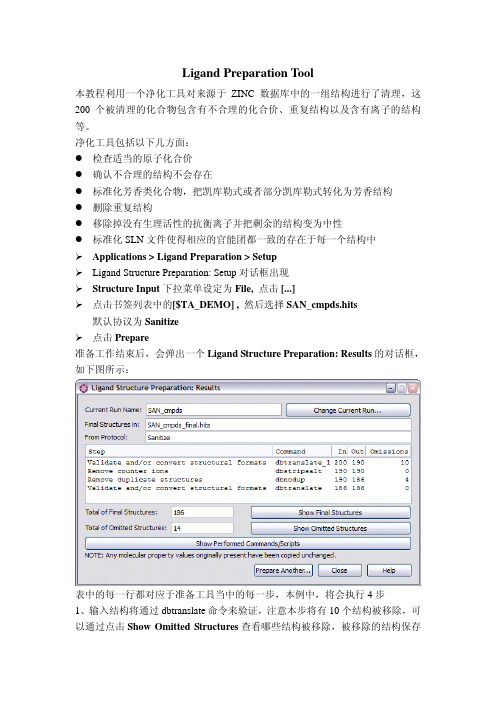
Ligand Preparation Tool本教程利用一个净化工具对来源于ZINC数据库中的一组结构进行了清理,这200个被清理的化合物包含有不合理的化合价、重复结构以及含有离子的结构等。
净化工具包括以下几方面:●检查适当的原子化合价●确认不合理的结构不会存在●标准化芳香类化合物,把凯库勒式或者部分凯库勒式转化为芳香结构●删除重复结构●移除掉没有生理活性的抗衡离子并把剩余的结构变为中性●标准化SLN文件使得相应的官能团都一致的存在于每一个结构中Applications > Ligand Preparation > SetupLigand Structure Preparation: Setup对话框出现Structure Input 下拉菜单设定为 File, 点击 [...]点击书签列表中的[$TA_DEMO] , 然后选择SAN_cmpds.hits 默认协议为Sanitize点击Prepare准备工作结束后,会弹出一个Ligand Structure Preparation: Results的对话框,如下图所示:表中的每一行都对应于准备工具当中的每一步,本例中,将会执行4步1、输入结构将通过dbtranslate命令来验证,注意本步将有10个结构被移除,可以通过点击Show Omitted Structures查看哪些结构被移除,被移除的结构保存在in SAN_cmpds.intm/dbtranslate_1.exc.中,剩余结构被保存在SAN_cmpds.intm /dbtranslate_1.sln中2、采用dbstripsalt命令对SAN_cmpds.intm/dbtranslate_1.sln文件进行抗衡离子或盐进行检测,文件中最后一个结构为盐cmpd_nsalt_na,本步的输出文件保存在SAN_cmpds.intm/dbstripsalt.sln中,在这一步没有结构被移除。

Reference number ISO 8536-4:2010(E)© ISO 2010INTERNATIONAL STANDARD ISO 8536-4Fifth edition 2010-10-01Infusion equipment for medical use — Part 4:Infusion sets for single use, gravity feedMatériel de perfusion à usage médical —Partie 4: Appareils de perfusion non réutilisables, à alimentation par gravitéISO 8536-4:2010(E)PDF disclaimerThis PDF file may contain embedded typefaces. In accordance with Adobe's licensing policy, this file may be printed or viewed but shall not be edited unless the typefaces which are embedded are licensed to and installed on the computer performing the editing. In downloading this file, parties accept therein the responsibility of not infringing Adobe's licensing policy. The ISO Central Secretariat accepts no liability in this area.Adobe is a trademark of Adobe Systems Incorporated.Details of the software products used to create this PDF file can be found in the General Info relative to the file; the PDF-creation parameters were optimized for printing. Every care has been taken to ensure that the file is suitable for use by ISO member bodies. In the unlikely event that a problem relating to it is found, please inform the Central Secretariat at the address given below.COPYRIGHT PROTECTED DOCUMENT© ISO 2010All rights reserved. Unless otherwise specified, no part of this publication may be reproduced or utilized in any form or by any means, electronic or mechanical, including photocopying and microfilm, without permission in writing from either ISO at the address below or ISO's member body in the country of the requester. ISO copyright officeCase postale 56 • CH-1211 Geneva 20 Tel. + 41 22 749 01 11 Fax + 41 22 749 09 47 E-mail copyright@ Web Published in Switzerlandii © ISO 2010 – All rights reservedISO 8536-4:2010(E)Contents PageForeword (iv)1Scope (1)2Normative references (1)3General requirements (1)4Designation (4)4.1Infusion set (4)4.2Air-inlet device (4)5Materials (4)6Physical requirements (5)6.1Particulate contamination (5)6.2Leakage (5)6.3Tensile strength (5)6.4Closure-piercing device (5)6.5Air-inlet device (5)6.6Tubing (6)6.7Fluid filter (6)6.8Drip chamber and drip tube (6)6.9Flow regulator (6)6.10Flow rate of infusion fluid (6)6.11Injection site (6)6.12Male conical fitting (6)6.13Protective caps (6)7Chemical requirements (7)7.1Reducing (oxidizable) matter (7)7.2Metal ions (7)7.3Titration acidity or alkalinity (7)7.4Residue on evaporation (7)7.5UV absorption of extract solution (7)8Biological requirements (7)8.1General (7)8.2Sterility (7)8.3Pyrogenicity (7)8.4Haemolysis (7)8.5Toxicity (8)9Labelling (8)9.1Unit container (8)9.2Shelf or multi-unit container (8)10Packaging (9)Annex A (normative) Physical tests (10)Annex B (normative) Chemical tests (14)Annex C (normative) Biological tests (16)Bibliography (17)© ISO 2010 – All rights reserved iiiISO 8536-4:2010(E)ForewordISO (the International Organization for Standardization) is a worldwide federation of national standards bodies (ISO member bodies). The work of preparing International Standards is normally carried out through ISO technical committees. Each member body interested in a subject for which a technical committee has been established has the right to be represented on that committee. International organizations, governmental and non-governmental, in liaison with ISO, also take part in the work. ISO collaborates closely with the International Electrotechnical Commission (IEC) on all matters of electrotechnical standardization.International Standards are drafted in accordance with the rules given in the ISO/IEC Directives, Part 2.The main task of technical committees is to prepare International Standards. Draft International Standards adopted by the technical committees are circulated to the member bodies for voting. Publication as an International Standard requires approval by at least 75 % of the member bodies casting a vote.Attention is drawn to the possibility that some of the elements of this document may be the subject of patent rights. ISO shall not be held responsible for identifying any or all such patent rights.ISO 8536-4 was prepared by Technical Committee ISO/TC 76, Transfusion, infusion and injection equipment for medical and pharmaceutical use.This fifth edition cancels and replaces the fourth edition (ISO 8536-4:2007), of which it constitutes a minor revision. In detail, 7.1 was more clarified in alignment with B.2, and A.2.2 was changed in order to go back with the leakage test pressure to 20 kPa and to restrict the leakage test for (40 ± 1) °C.ISO 8536 consists of the following parts, under the general title Infusion equipment for medical use:⎯Part 1: Infusion glass bottles⎯Part 2: Closures for infusion bottles⎯Part 3: Aluminium caps for infusion bottles⎯Part 4: Infusion sets for single use, gravity feed⎯Part 5: Burette infusion sets for single use, gravity feed⎯Part 6: Freeze drying closures for infusion bottles⎯Part 7: Caps made of aluminium-plastics combinations for infusion bottles⎯Part 8: Infusion equipment for use with pressure infusion apparatus⎯Part 9: Fluid lines for use with pressure infusion equipment⎯Part 10: Accessories for fluid lines for use with pressure infusion equipment⎯Part 11: Infusion filters for use with pressure infusion equipment⎯Part 12: Check valvesiv © ISO 2010 – All rights reservedINTERNATIONAL STANDARD ISO 8536-4:2010(E)Infusion equipment for medical use —Part 4:Infusion sets for single use, gravity feed1 ScopeThis part of ISO 8536 specifies requirements for single use, gravity feed infusion sets for medical use in order to ensure their compatibility with containers for infusion solutions and intravenous equipment.Secondary aims of this part of ISO 8536 are to provide guidance on specifications relating to the quality and performance of materials used in infusion sets and to present designations for infusion set components.In some countries, the national pharmacopoeia or other national regulations are legally binding and take precedence over this part of ISO 8536.2 Normative referencesThe following referenced documents are indispensable for the application of this document. For dated references, only the edition cited applies. For undated references, the latest edition of the referenced document (including any amendments) applies.ISO 594-1, Conical fittings with a 6 % (Luer) taper for syringes, needles and certain other medical equipment — Part 1: General requirementsISO 594-2, Conical fittings with 6 % (Luer) taper for syringes, needles and certain other medical equipment — Part 2: Lock fittingsISO 3696, Water for analytical laboratory use — Specification and test methodsISO 7864, Sterile hypodermic needles for single useISO 14644-1, Cleanrooms and associated controlled environments — Part 1: Classification of air cleanliness1) ISO 15223-1, Medical devices — Symbols to be used with medical device labels, labelling and information to be supplied — Part 1: General requirements2)3 General requirements3.1 The nomenclature to be used for components of infusion sets and of a separate air-inlet device is given in Figures 1, 2 and 3. These figures illustrate examples of the configuration of infusion sets and air-inlet devices; other configurations may be used provided they lead to the same results. Infusion sets as illustrated in Figure 2 should only be used for collapsible plastic containers. Infusion sets as illustrated in Figure 2 used1) Under preparation. (Revision of ISO 14644-1:1999)2) To be published. (Revision of ISO 15223-1:2007)© ISO 2010 – All rights reserved1ISO 8536-4:2010(E)with separate air-inlet devices as illustrated in Figure 3, or infusion sets as illustrated in Figure 1, shall be used for rigid containers.3.2 The infusion set shall be provided with protective caps to maintain sterility of the internal parts of the set until the set is used. The air-inlet device shall be provided with a protective cap over the closure-piercing device or needle.Key1 protective cap of closure-piercing device 7 fluid filter2 closure-piercing device 8 tubing3 air inlet with air filter and closure 9 flow regulator4 fluid channel 10 injection site5 drip tube 11 male conical fitting6 drip chamber 12 protective cap of male conical fittinga Closure of the air inlet is optional.b The fluid filter may be positioned at other sites, preferably near the patient access. Generally, the fluid filter used has anominal pore size of 15 µm.c The injection site is optional.Figure 1 — Example of a vented infusion set2 © ISO 2010 – All rights reservedISO 8536-4:2010(E)Key1 protective cap of closure-piercing device 7 tubing2 closure-piercing device 8 flow regulator3 fluid channel 9 injection site4 drip tube 10 male conical fitting5 drip chamber 11 protective cap of the male conical fitting6 fluid filtera The fluid filter may be positioned at other sites, preferably near the patient access. Generally, the fluid filter used has anominal pore size of 15 µm.b The injection site is optional.Figure 2 — Example of a non-vented infusion set© ISO 2010 – All rights reserved3ISO 8536-4:2010(E)Key1 protective cap 4 clamp2 closure-piercing device or needle 5 air-inlet with air filter3 tubinga Other designs are acceptable if the same safety aspects are ensured.Figure 3 — Example of an air-inlet device4 Designation4.1 Infusion setInfusion sets complying with the requirements specified in this part of ISO 8536 shall be designated by the descriptor words, followed by a reference to this part of ISO 8536, followed by the letters IS, followed by the letter G:Infusion set ISO 8536-4 - IS - G4.2 Air-inlet deviceAir-inlet devices complying with the requirements specified in this part of ISO 8536 shall be designated by the descriptor words, followed by a reference to this part of ISO 8536, followed by the letters IS, followed by the letters AD:Air-inlet device ISO 8536-4 - IS - AD5 MaterialsThe materials from which the infusion set and its components are manufactured (as described in Clause 3) shall comply with the requirements specified in Clause 6. Where components of the infusion set come into contact with solutions, the materials shall also comply with the requirements specified in Clauses 7 and 8.4 © ISO 2010 – All rights reservedISO 8536-4:2010(E)6 Physical requirements6.1 Particulate contaminationThe infusion sets shall be manufactured under conditions that minimize particulate contamination. All parts shall be smooth and clean at the fluid pathway surfaces. When tested as specified in A.1, the number of particles shall not exceed the contamination index limit.6.2 LeakageThe infusion set, when tested in accordance with A.2, shall show no signs of air leakage.6.3 Tensile strengthWhen tested as specified in A.3, the infusion set, excluding protective caps, shall withstand a static tensile force of not less than 15 N for 15 s.6.4 Closure-piercing deviceThe dimensions of the closure-piercing device shall conform to the dimensions shown in Figure 4.NOTE The dimension of 15 mm in Figure 4 is a reference measurement. The cross-section of the piercing device at this site is a circle.The closure-piercing device shall be capable of piercing and penetrating the closure of a fluid container without pre-piercing. No coring should occur during this procedure.Dimensions in millimetresFigure 4 — Dimensions of the closure-piercing device6.5 Air-inlet deviceThe air-inlet device shall conform to 3.2 and 8.2.The air-inlet device shall be provided with an air filter to prevent the ingress of microorganisms into the container into which the device is to be inserted.The air-inlet device shall be separate from, or integral with, the closure-piercing device.When the air-inlet device is inserted into a rigid infusion container, the air admitted into the container shall not become entrained in the liquid outflow.The air filter shall be fitted such that all air entering the rigid container passes through it, and such that the flow of fluid is not reduced by more than 20 % of that from a freely ventilated container when tested in accordance with A.4.© ISO 2010 – All rights reserved5ISO 8536-4:2010(E)6.6 TubingThe tubing, made of flexible material, shall be transparent or sufficiently translucent that the interface of air and water during the passage of air bubbles can be observed with normal or corrected vision.The tubing from the distal end to the drip chamber shall be not less than 1 500 mm in length, including the injection site, when provided, and the male conical fitting.6.7 Fluid filterThe infusion set shall be provided with a fluid filter.When tested in accordance with A.5, the retention of latex particles on the filter shall be not less than 80 %. 6.8 Drip chamber and drip tubeThe drip chamber shall permit continuous observation of the fall of drops. The liquid shall enter the drip chamber through a tube that projects into the chamber. There shall be a distance of not less than 40 mm between the end of the drip tube and the outlet of the chamber, or a distance of not less than 20 mm between the drip tube and the fluid filter. The wall of the drip chamber shall not be closer than 5 mm to the end of the drip tube. The drip tube shall be such that 20 drops of distilled water or 60 drops of distilled water at (23 ± 2) °C at a flow rate of (50 ± 10) drops/min deliver a volume of (1 ± 0,1) ml or a mass of (1 ± 0,1) g. The drip chamber should permit and facilitate the priming procedure.6.9 Flow regulatorThe flow regulator shall adjust the flow of the infusion solution between zero and the maximum. The flow regulator should be capable of continuous use throughout an infusion without the tubing being damaged. There should be no deleterious reaction between the flow regulator and the tubing when they are stored in such a way that there is contact.6.10 Flow rate of infusion fluidThe infusion set shall deliver not less than 1 000 ml of a sodium chloride solution [mass concentration ρ(NaCl) = 9 g/l] in 10 min under a static head of 1 m.6.11 Injection siteWhen provided, the self-sealing injection site shall reseal when tested in accordance with A.6, and there shall be no leakage of more than one falling drop of water. The injection site should be located near the male conical fitting.6.12 Male conical fittingThe distal end of the tubing shall terminate in a male conical fitting in accordance with ISO 594-1 or ISO 594-2. Luer lock fittings in accordance with ISO 594-2 should preferably be used.6.13 Protective capsThe protective caps at the end of the infusion set shall maintain the sterility of the closure-piercing device, the male conical fitting and the interior of the infusion set. Protective caps should be secure but easily removable.6 © ISO 2010 – All rights reserved7 Chemical requirements7.1 Reducing (oxidizable) matterWhen tested in accordance with B.2, the difference of volume of Na2S2O3 solution [c(Na2S2O3) = 0,005 mol/l] for the extract solution S1 and of volume of Na2S2O3 solution for blank solution S0 shall not exceed 2,0 ml. 7.2 Metal ionsThe extract shall not contain in total more than 1 µg/ml of barium, chromium, copper, lead and tin, and not more than 0,1 µg/ml of cadmium, when determined by atomic absorption spectroscopy (AAS) or an equivalent method.When tested in accordance with B.3, the intensity of the colour produced in the test solution shall not exceed that of the standard matching solution with a mass concentration ρ(Pb2+) = 1 µg/ml.7.3 Titration acidity or alkalinityWhen tested in accordance with B.4, not more than 1 ml of either standard volumetric solution shall be required for the indicator to change to the colour grey.7.4 Residue on evaporationWhen tested in accordance with B.5, the total amount of dry residue shall not exceed 5 mg.7.5 UV absorption of extract solutionWhen tested in accordance with B.6, the extract solution S1 shall not show absorption greater than 0,1.8 Biological requirements8.1 GeneralThe infusion set shall be assessed for biological compatibility according to the guidelines given in C.2.8.2 SterilityThe infusion set or the air-inlet device, or both, in its unit container shall have been subjected to a validated sterilization process (see ISO 11135, ISO 11137 and ISO 17665).8.3 PyrogenicityThe infusion set and/or the air-inlet device shall be assessed for freedom from pyrogens by using a suitable test, and the results shall indicate that the infusion set is free from pyrogens. Guidance on testing for pyrogenicity is given in C.1.8.4 HaemolysisThe infusion set shall be assessed for freedom from haemolytic constituents and the result shall indicate that the infusion set is free from haemolytic reactions. Guidance on testing for haemolytic constituents is given in ISO 10993-4.© ISO 2010 – All rights reserved78.5 ToxicityMaterials shall be assessed for toxicity by carrying out suitable tests, and the results of the tests shall indicate freedom from toxicity. Guidance on testing for toxicity is given in ISO 10993-1.9 Labelling9.1 Unit containerThe unit container shall be labelled with at least the following information:a) a textual description of the contents, including the words “Gravity feed only”;b) indication that the infusion set is sterile, using the graphical symbol as given in ISO 15223-1;c) indication that the infusion set is free from pyrogens, or that the infusion set is free from bacterialendotoxins;d) indication that the infusion set is for single use only, or equivalent wording, or using the graphical symbolin accordance with ISO 15223-1;e) instructions for use, including warnings, e.g. about detached protective caps;NOTE Instructions for use can also take the form of an insert.f) the lot (batch) designation, prefixed by the word LOT, or using the graphical symbol in accordance withISO 15223-1;g) year and month of expiry, accompanied by appropriate wording or the graphical symbol in accordancewith ISO 15223-1;h) the manufacturer's or supplier's name and address, or both;i) a statement that 20 drops of distilled water or 60 drops of distilled water delivered by the drip tube areequivalent to a volume of (1 ± 0,1) ml or a mass of (1 ± 0,1) g;j) the nominal dimensions of the intravenous needle, if included.9.2 Shelf or multi-unit containerThe shelf or multi-unit container, when used, shall be labelled with at least the following information:a) a textual description of the contents, including the words “Gravity feed only”;b) the number of infusion sets;c) indication that the infusion sets are sterile, using the graphical symbol as given in ISO 15223-1;d) the lot (batch) designation, prefixed by the word LOT, or using the graphical symbol in accordance withISO 15223-1;e) year and month of expiry, accompanied by appropriate wording or the graphical symbol in accordancewith ISO 15223-1;f) the manufacturer's and/or supplier's name and address;g) the recommended storage conditions, if any.10 Packaging10.1 The infusion set and/or the air-inlet device shall be individually packed so that they remain sterile during storage. The unit container shall be sealed in a tamper-evident manner.10.2 The infusion sets and/or the air-inlet devices shall be packed and sterilized in such a way that there are no flattened portions or kinks when they are ready for use.© ISO 2010 – All rights reserved9Annex A(normative)Physical testsA.1 Test for particulate contaminationA.1.1 PrincipleThe particles are rinsed from the inner fluid pathway surfaces of the infusion set, collected on a membrane filter and microscopically counted.A.1.2 Reagents and materialsA.1.2.1 Distilled water,filtered through a membrane of pore size 0,2 µm.A.1.2.2 Non-powdered gloves.A.1.2.3 Vacuum filter, single membrane filter of pore size 0,45 µm.A.1.3 ProcedureThe filter unit, filter and all other equipment shall be thoroughly cleaned before the test using distilled water (A.1.2.1).Flush through 10 ready-to-use infusion appliances, under laminar flow conditions (clean-air work station class N5 in accordance with ISO 14644-1), with 500 ml of distilled water (A.1.2.1). The total volume is subsequently vacuum filtered (A.1.2.3). Place the particles on the membrane screen filter under a microscope at ×50 magnification using diagonally incident illumination, and measure and count in accordance with the size categories given in Table A.1.A.1.4 Determination of resultsA.1.4.1 GeneralAn appropriate number of single infusion sets (minimum of 10) are tested. The number of particles per10 infusion sets tested in each of the three size categories is the assay result.A.1.4.2 Particle countsThe values obtained from a blank control sample shall be recorded in a test report and taken into account when calculating the contamination index limit.The blank control sample is the number and size of particles obtained from 10 equivalent 500 ml water samples classified in accordance with the three size categories set out in Table A.1, using the same test equipment but not passed through the appliances under test.The number of particles in the blank, N b, shall not exceed the value of 9. Otherwise, the test apparatus shall be disassembled, re-cleaned, and the background test performed again. Values of the blank determination shall be noted in the test report.Table A.1 — Evaluation of contamination by particlesSize categoryParticle parameters1 2 3 Particle size in µm 25 to 50 51 to 100 over 100Number of particles in 10 infusion appliances n a1n a2n a3Number of particles in the blank control sample n b1n b2n b3Evaluation coefficient 0,1 0,2 5The contamination index limit is calculated as follows.For each of the three size categories, multiply the number of particles in 10 infusion appliances by the evaluation coefficients, and add the results in order to obtain the number of particles in the infusion appliances(test pieces), N a. Then, for each of the size categories, multiply the number of particles in the blank control sample by the evaluation coefficients and add the results to obtain the number of particles in the blank sample,N b.Subtract N b from N a to obtain the contamination index limit.Number of particles in the infusion appliances (test pieces):N a=n a1× 0,1 +n a2× 0,2 +n a3× 5Number of particles in the blank sample:N b=n b1× 0,1 +n b2× 0,2 +n b3× 5Contamination index limit:N=N a−N b u 90A.2 Test for leakageA.2.1 At the beginning of the test, condition the whole system at the test temperature.A.2.2 Immerse the infusion set, with one end blocked, in water at (40 ±1) °C and apply an internal air pressure of 20 kPa for 15 s. Examine the infusion set for air leakage.A.2.3 Fill the infusion set with degassed, distilled water, connect it with its openings sealed to a vacuumdevice and subject it to an internal excess pressure of −20 kPa at (40 ± 1) °C for 15 s. Atmospheric pressureshall be the reference pressure. Excess pressure, in accordance with ISO 80000-4, can assume positive or negative values. Ascertain whether air enters the infusion set.A.3 Test for tensile strengthExpose the infusion set to be tested to a static tensile force of 15 N applied along the longitudinal axis for 15 s. Inspect whether the infusion set withstands the test force applied.© ISO 2010 – All rights reserved11A.4 Determination of flow rate when using an air-inlet deviceA.4.1 Fill an infusion container with distilled water at (23 ± 2) °C and insert its closure. Insert the air-inlet device through the closure into the container and then insert the infusion set with the flow regulator set, such that no liquid flows. Arrange the container to give the equivalent of a pressure of 1 m head of water throughout the test. Open the flow regulator of the infusion set to maximum and measure the rate of flow of water from the set. Repeat the procedure with the filter removed from the air-inlet device.A.4.2 For air-inlet devices integral with the closure-piercing device of the infusion set, follow the procedure given in A.4.1 but omit the insertion of the separate air-inlet device.A.5 Test for efficiency of the fluid filterA.5.1 Preparation of the test fluidAs a test liquid, use an aqueous suspension of latex particles with a diameter of (20 ± 1) µm and a concentration of approximately 1 000 particles per 100 ml.A.5.2 ProcedureAssemble the fluid filter and position it so that it is equivalent to that of actual use in a suitable test apparatus in accordance with Figure A.1. Cut the tubing of the infusion set approximately 100 mm below the fluid filter. Flush the fluid filter with 5 ml of the test fluid from the storage bottle and discard the filtrate. Pass 100 ml of the test fluid through the fluid filter and collect the effluent under vacuum after passing it through a black gridded membrane filter with a pore size of 5 µm to 8 µm and 47 mm diameter. Mount the membrane with any retained latex particles on a suitable microscope slide or holder and count the latex particles in a minimum of 50 % of the grid squares under a magnification of ×50 to ×100. Disregard any particles which are obviously non-latex.Carry out the test in duplicate.Repeat the test if the required limit value of 80 % retention rate is not met.All procedures involved in this test should be conducted in a clean environment, if possible under laminar flow.A.5.3 Expression of results The retention rate of the filter, expressed as a percentage, is given by101100n n ⎛⎞−×⎜⎟⎝⎠ (A.1)wheren 1 is the number of particles retained on the filter;n 0 is the number of particles in the test fluid used.Dimensions in millimetresKey1 storage bottle 5 piercing device2 transfer tube 6 fluid filter3 flow regulator 7 membrane filter4 connecting pieceFigure A.1 — Apparatus for testing the efficiency of the fluid filterA.6 Test of the injection sitePlace the injection site in a horizontal, stress-free position. Fill the infusion set with water in such a manner that no air bubbles are trapped and apply a pressure of 50 kPa above the atmospheric air pressure. Perforate the injection site at the foreseen area using a hypodermic needle with an outside diameter of 0,8 mm and which conforms to ISO 7864. Keep the needle in position for 15 s. Remove the needle and immediately dry the perforated site. Over a period of 1 min, observe whether there is any leakage from the injection site. In the case of an alternative injection site design, the test should be performed by injection into the site in accordance with the instructions provided by the manufacturer.© ISO 2010 – All rights reserved13。

医药行业专业英语词汇(非常有用)FDA和EDQM术语: CLINICAL?TRIAL:临床试验? ANIMAL?TRIAL:动物试验? ACCELERATED?APPROVAL:加速批准? STANDARD?DRUG:标准药物? INVESTIGATOR:研究人员;调研人员 PREPARING?AND?SUBMITTING:起草和申报? SUBMISSION:申报;递交? BENIFIT (S):受益? RISK(S):受害? DRUG?PRODUCT:药物产品? DRUG?SUBSTANCE:原料药? ESTABLISHED?NAME:确定的名称? GENERIC?NAME:非专利名称? PROPRIETARY?NAME:专有名称;? INN(INTERNATIONAL?NONPROPRIETARY?NAME):国际非专有名称? ADVERSE?EFFECT:副作用? ADVERSE?REACTION:不良反应? PROTOCOL:方案? ARCHIVAL?COPY:存档用副本? REVIEW?COPY:审查用副本? OFFICIAL?COMPENDIUM:法定药典(主要指USP、?NF).? USP (THE?UNITED?STATES?PHARMACOPEIA):美国药典 NF(NATIONAL?FORMULARY):(美国)国家处方集? OFFICIAL=PHARMACOPEIAL=?COMPENDIAL:药典的;法定的;官方的? AGENCY:审理部门(指FDA)? IDENTITY:真伪;鉴别;特性? STRENGTH:规格;规格含量(每一剂量单位所含有效成分的量)? LABELED?AMOUNT:标示量? REGULATORY?SPECIFICATION:质量管理规格标准(NDA提供)? REGULATORY?METHODOLOGY:质量管理方法? REGULATORY?METHODS?VALIDATION:管理用分析方法的验证 COS/CEP?欧洲药典符合性认证ICH(International?Conference?on?Harmonization?of?Technical?Requirements?for?Reg istration?of?Pharmaceuticals?for?Human?Use)人用药物注册技术要求国际协调会议ICH文件分为质量、安全性、有效性和综合学科4类。

中国组织工程研究 第18卷 第51期 2014–12–10出版Chinese Journal of Tissue Engineering Research December 10, 2014 Vol.18, No.51ISSN 2095-4344 CN 21-1581/R CODEN: ZLKHAH8201www.CRTER.org孙志涛,男,1978年生,安徽省淮南市人,汉族,2013年广州中医药大学毕业,博士,主要从事脊柱、髋膝关节退行性变研究。
doi:10.3969/j.issn.2095-4344. 2014.51.001 []中图分类号:R318 文献标识码:A 文章编号:2095-4344 (2014)51-08201-05 稿件接受:2014-10-29Sun Zhi-tao, M.D., Shenzhen Hospital of Traditional Chinese Medicine, Shenzhen 518000, Guangdong Province, ChinaAccepted: 2014-10-29不同方法提取SD 大鼠膝关节软骨组织的总RNA孙志涛1,牛 维2,何升华1,林定坤2 (1深圳市中医院,广东省深圳市 518000;2广东省中医院骨三科,广东省广州市 510120)文章亮点:1 目前文献报道的软骨RNA 提取有多钟方法,常见的有Rneasy Lipid Tissue Kit 、RNAout 试剂盒和经典Trizol 法,国内文献报道多为经典Trizol 法。
作者在实验中发现该方法提取的RNA 并不能满足后续实验的需要,为了解决这个瓶颈,作者尝试了各种方法。
2 比较目前文献报道的常见3种不同方法提取的软骨组织RNA ,结果显示Rneasy Lipid Tissue Kit 法获得的总RNA 纯度高、完整性和稳定性好,并能成功反转录合成双链cDNA 。
关键词:组织构建;软骨组织构建;软骨;RNA 提取;大鼠;国家自然科学基金 主题词:软骨;RNA ;大鼠 基金资助:国家自然科学基金项目(81173285)摘要背景:目前文献报道的软骨RNA 提取有多钟方法,国内文献报道多为经典Trizol 法,在实验中发现该方法提取的RNA 并不能满足后续实验的需要。

MILLIPORE实验级切向流浓缩纯化透析系统中文操作手册P73614C Rev. A 7/2000Millipore BioProcess Division © 2000目录1.介绍2.系统预览/组件清单2.1 实验级切向流浓缩纯化透析系统………………......…….......................................................2-22.2 500 mL 样品槽...................………………...............……...........................……………......2-42.3 磁式搅拌器及隔膜式泵底座….........……...................................……….……………............2-52.5 Pellicon XL 50 cm2管匣…...............…….....................…………………...........................2-62.6 使用者需提供之材料…..................……......................………………................................2-63.实验级切向流浓缩纯化透析系统安装3.1 500 mL 样品槽之安装.................................……………………………......................……3-33.2 磁式搅拌器之安装......................................................………………..………..........……..3-53.3 隔膜式泵模块之安装...............................................………………............…………….3-64.系统清洗(不包含Pellicon XL管匣)4.1 安装清洗管线..............................................................………………….............………….4-24.2 清洗系统....................................................................………………….................………...4-24.3 液体排空......................................................................………………............…………......4-34.4 系统冲洗......................................................................………………...............………….....4-45.冲洗Pellicon XL管匣5.1 安装l Pellicon XL 管匣...............................................……………….....................…….........5-25.2 冲洗管匣 ......................................................................………………..................………........5-25.3 排空系统液体..............................................................………………..................……........5-35.4 完整性测试- Pellicon XL Device on System ............……………….............……….........5-35.5 预湿润管匣……………….......................................................................…………............5-55.6 浓缩…….......…………………..................................................................……………….....5-55.7 样品回收………………........................................................................……………............5-65.8 透析应用–真空吸入法………….…………….................................................................5-76.关机6.1 清洗管匣......……………….................................................................…………….............6-26.2 清洗系统.....…………………..................................................................…………..................6-26.3 排空系统液体………………..........................................................................……................6-36.4 冲洗管匣……………….......................................................................……………............6-36.5 清洗样品槽................................………………............................................……................6-37.规格7.1 规格...........................................………………….........................……………....................7-27.2 主体材料成分..........................…………………......................…………………....................7-28.采购信息8.1 系统产品编号.........................…………………..........................……………….....................8-28.2 各主要组件产品编号………………………….……………………….…….......................8-28.3 泵及泵头产品编号………………................………...…......................................8-28.4 Pellicon XL 管匣产品编号..…………………..........................................................................8-29.实验级切向流浓缩纯化透析系统之维护9.1 磁式搅拌器组件产品编号………...…………………........................…….............................9-39.2 500 mL 样品槽组件产品编号………………..............……….............................................9-49.3 泵组件产品编号………………...................………………….........................................9-69.4 泵逆止阀之冲洗……………….………………………………...........................................9-79.5 隔膜式泵之维护………………..............……………….....................................................9-89.6 电路图…………………...........................………………….....................................................9-1010.实验级切向流浓缩纯化透析系统之故障排除电源/ 控制..................................……………................………………........................................10-2 效能…................................................................………………........................................................ 10-2 压力……………………...................................................………….................................................10-3介绍图一、实验级切向流浓缩纯化透析系统实验级切向流浓缩纯化透析系统为一套专为Pellicon XL 超过滤膜管匣而设计之简单且容易操作的系统。
extract_instruments参数下载温馨提示:该文档是我店铺精心编制而成,希望大家下载以后,能够帮助大家解决实际的问题。
文档下载后可定制随意修改,请根据实际需要进行相应的调整和使用,谢谢!并且,本店铺为大家提供各种各样类型的实用资料,如教育随笔、日记赏析、句子摘抄、古诗大全、经典美文、话题作文、工作总结、词语解析、文案摘录、其他资料等等,如想了解不同资料格式和写法,敬请关注!Download tips: This document is carefully compiled by the editor. I hope that after you download them, they can help you solve practical problems. The document can be customized and modified after downloading, please adjust and use it according to actual needs, thank you!In addition, our shop provides you with various types of practical materials, such as educational essays, diary appreciation, sentence excerpts, ancient poems, classic articles, topic composition, work summary, word parsing, copy excerpts, other materials and so on, want to know different data formats and writing methods, please pay attention!提取乐器参数:在音乐信号处理中的应用引言在音乐信号处理领域,提取乐器参数是一项重要的任务。
实验室药材溶剂提取流程英文回答:Laboratory Solvent Extraction Process for Medicinal Plants.The solvent extraction process is a widely used technique in the pharmaceutical industry for extracting active compounds from medicinal plants. This process involves the use of solvents to dissolve and remove the desired compounds from the plant material. The choice of solvent is crucial as it should be able to selectively extract the target compounds while minimizing the extraction of unwanted impurities.Steps Involved in Solvent Extraction.The laboratory solvent extraction process typically involves the following steps:1. Sample Preparation: The plant material is dried, ground, and sieved to obtain a uniform particle size.2. Solvent Selection: The appropriate solvent is chosen based on the polarity and solubility of the target compounds.3. Extraction: The ground plant material is mixed with the selected solvent and agitated to facilitate the extraction process.4. Filtration: The mixture is filtered to separate the extracted solution from the plant solids.5. Concentration: The extracted solution is concentrated using rotary evaporation or freeze drying to remove the solvent.6. Purification: The concentrated extract may undergo further purification steps, such as column chromatography or recrystallization, to isolate the desired compounds.Factors Affecting Solvent Extraction.Several factors can affect the efficiency of the solvent extraction process, including:Solvent Polarity: Polar solvents are more effective at extracting polar compounds, while nonpolar solvents are better suited for nonpolar compounds.Temperature: Increasing the temperature can enhance the solubility of the target compounds and improve extraction efficiency.Extraction Time: Longer extraction times allow for greater extraction of the desired compounds.Solid-to-Solvent Ratio: The ratio of plant material to solvent can influence the extraction yield.Agitation: Agitation promotes better contact between the plant material and solvent, improving extraction efficiency.Applications of Solvent Extraction.Solvent extraction is a versatile technique used in the pharmaceutical industry for the following applications:Extraction of Active Ingredients: Solvent extraction is employed to isolate active compounds from medicinal plants for use in drug development and production.Standardization of Herbal Products: Solvent extraction allows for the standardization of herbal products by ensuring consistent levels of active ingredients.Quality Control: Solvent extraction is used to analyze and control the quality of herbal products by detecting the presence of specific compounds or impurities.中文回答:实验室药材溶剂提取流程。
2Preparation of Extracts From Animal TissuesJ. Mark Skehel1. IntroductionThe initial procedure in the isolation of an protein,a protein complex,or a subcellu-lar organelle is the preparation of an extract that contains the required component in a soluble form. Indeed,when undertaking a proteomic study,the production of a suitable cellular extract is essential. Further isolation of subcellular fractions depends on the abil-ity to rupture the animal tissues in such a manner that the organelle or macromolecule of interest can be purified in a high yield,free from contaminants and in an active form. The homogenization technique employed should,therefore,stress the cells sufficiently enough to cause the surface plasma membrane to rupture,thus releasing the cytosol; however,it should not cause extensive damage to the subcellular structures,organelles, and membrane vesicles. The extraction of proteins from animal tissues is relatively straightforward,as animal cells are enclosed only by a surface plasma membrane (also referred to as the limiting membrane or cell envelope) that is only weakly held by the cytoskeleton. They are relatively fragile compared to the rigid cell walls of many bac-teria and all plants and are thus susceptible to shear forces. Animal tissues can be crudely divided into soft muscle (e.g.,liver and kidney) or hard muscle (e.g.,skeletal and car-diac). Reasonably gentle mechanical forces such as those produced by liquid shear may disrupt the soft tissues,whereas the hard tissues require strong mechanical shear forces provided by blenders and mincers. The homogenate produced by these disruptive meth-ods is then centrifuged in order to remove the remaining cell debris.The subcellular distribution of the protein or enzyme complex should be considered. If located in a specific cellular organelle such as the nuclei,mitochondria,lysosomes, or endoplasmic reticulum,then an initial subcellular fractionation to isolate the specific organelle can lead to a significant degree of purification in the first stages of the ex-periment (1). Subsequent purification steps may also be simplified,as contaminating proteins may be removed in the centrifugation steps. In addition,the deleterious affects of proteases released as a result of the disruption of lysosomes may also be avoided. Proteins may be released from organelles by treatment with detergents or by disrup-tion resulting from osmotic shock or ultrasonication. Although there is clearly an ad-From:Methods in Molecular Biology, vol. 244: Protein Purification Protocols: Second EditionEdited by: P. Cutler © Humana Press Inc., Totowa, NJ1516Skehel vantage in producing a purer extract,yields of organelles are often low,so considera-tion has to be made to the acceptability of a lower final yield of the desired protein.Following production of the extract,some proteins will inevitably remain insoluble. For animal tissues,these generally fall into two categories:membrane-bound proteins and extracellular matrix proteins. Extracellular matrix proteins such as collagen and elastin are rendered insoluble because of extensive covalent crosslinking between lysine residues after oxidative deamination of one of the amino groups. These proteins can only be solubilized following chemical hydrolysis or proteolytic cleavage.Membrane-bound proteins can be subdivided into integral membrane proteins,where the protein or proteins are integrated into the hydrophobic phospholipid bilayer,or ex-trinsic membrane proteins,which are associated with the lipid membrane resulting from interactions with other proteins or regions of the phospholipid bilayer. Extrinsic mem-brane proteins can be extracted and purified by releasing them from their membrane an-chors with a suitable protease. Integral membrane proteins,on the other hand,may be extracted by disruption of the lipid bilayer with a detergent or,in some cases,an organic solvent. In order to maintain the activity and solubility of an integral membrane pro-tein during an entire purification strategy,the hydrophobic region of the protein must in-teract with the detergent micelle. Isolation of integral membrane proteins is thought to occur in four stages,where the detergent first binds to the membrane,membrane lysis then occurs,followed by membrane solubilization by the detergent,forming a de-tergent–lipid–protein complex. These complexes are then further solubilized to form detergent–protein complexes and detergent–lipid complexes. The purification of mem-brane proteins is,therefore,not generally as straightforward as that for soluble pro-teins(2,3).The principal aim of any extraction method must be that it be reproducible and dis-rupt the tissue to the highest degree,using the minimum of force. In general,a cellular disruption of up to 90% should be routinely achievable. The procedure described here is a general method and can be applied,with suitable modifications,to the preparation of tissue extracts from both laboratory animals and from slaughterhouse material (4,5). In all cases tissues,should be kept on ice before processing. However,it is not gener-ally recommended that tissues be stored frozen prior to the preparation of extracts. 2. MaterialsThe preparation of extracts from animal tissues requires normal laboratory glassware, equipment,and reagents. All glassware should be thoroughly cleaned. If in doubt,clean by immersion in a sulfuric–nitric acid bath. Apparatus should then be thoroughly rinsed with deionized and distilled water. Reagents should be Analar grade or equivalent. In addition,the following apparatuses are required:1.Mixers and blenders:In general,laboratory apparatus of this type resemble their householdcounterparts. The Waring blender is most often used. It is readily available from general laboratory equipment suppliers and can be purchased in a variety of sizes,capable of han-dling volumes from 10 mL to a few liters. Vessels made from stainless steel are preferable, as they retain low temperatures when prechilled,thus counteracting the effects of any heat produced during cell disruption.2.Refrigerated centrifuge:Various types of centrifuge are available,manufacturers of whichare Beckman,Sorval-DuPont,and MSE. The particular centrifuge rotor used depends onPreparation of Extracts From Animal Tissues17 the scale of the preparation in hand. Generally,for the preparations of extracts,a six-posi-tion fixed-angle rotor capable of holding 250-mL tubes will be most useful. Where larger-scale preparations are undertaken,a six-position swing-out rotor capable of accommodat-ing 1-L containers will be required.3.Centrifuge tubes:Polypropylene tubes with screw caps are preferable,as they are morechemically resistant and withstand higher g forces than other materials such as polycar-bonate. In all cases,the appropriate tubes for the centrifuge rotor should be used.3. MethodsAll equipment and reagents should be prechilled to 0–4°C. Centrifuges should be turned on ahead of time and allowed to cool down.1.First,trim fat,connective tissue,and blood vessels from the fresh chilled tissue and diceinto pieces of a few grams (see Note 1).2.Place the tissue in the precooled blender vessel (see Note 2) and add cold extraction bufferusing 2–2.5 vol of buffer by weight of tissue (see Note 3). Use a blender vessel that has a capacity approximately that of the volume of buffer plus tissue so that the air space is min-imized; this will reduce aerosol formation.3.Homogenize at full speed for 1–3 min depending on the toughness of the tissue. For longperiods of homogenization,it is best to blend in 40-s to 1-min bursts with a few minutes in between to avoid excessive heating. This will also help reduce foaming.4.Remove cell debris and other particulate matter from the homogenate by centrifugation at4°C. For large-scale work,use a 6 ϫ1000-mL swing-out rotor operated at about 600–3000g for 30 min. For smal-scale work (up to 3 L of homogenate),a 6 ϫ250-mL angle rotor op-erated at 5000g would be more appropriate (see Note 4).5.Decant the supernatant carefully,avoiding disturbing the sedimented material,through adouble layer of cheesecloth or muslin. This will remove any fatty material that has floated to the top. Alternatively,the supernatant may be filtered by passing it through a plug of glass wool placed in a filter funnel. The remaining pellet and intermediate fluffy layer may be re-extracted with more buffer to increase the yield (see Note 5) or discarded.The crude extract obtained by the above procedure will vary in clarity depending on the tissue from which it was derived. Before further fractionation is undertaken,addi-tional clarification steps may be required (see Note 6).4. Notes1.The fatty tissue surrounding the organ/tissue must be scrupulously removed prior to ho-mogenization,as it can often interfere with subsequent protein isolation from the homog-enate.2.Where only small amounts of a soft tissue (1–5 g) such as liver,kidney,or brain are beinghomogenized,then it may be easier to use a hand-held Potter–Elvehjem homogenizer (6).This will release the major organelles; nuclei,lysosomes,peroxisomes,and mitochondria(7). The endoplasmic reticulum,smooth and rough,will vesiculate,as will the Golgi if ho-mogenization conditions are too severe. On a larger scale,these soft tissues are easily dis-rupted/homogenized in a blender. However,tissues such as skeletal muscle,heart,and lung are too fibrous in nature to place directly in the blender and must first be passed through a meat mincer,equipped with rotating blades,to grind down the tissue before homogeniza-tion (8,9). As the minced tissue emerges from the apparatus,it is placed directly into an ap-proximately equal volume by weight of a suitable buffer. This mixture is then squeezed18Skehel Table 1Protease InhibitorsEffectiveInhibitor Target proteases concentrations Stock solutions EDTA Metalloproteases0.5–2.0 m M500 m M in water,pH 8.0 Leupeptin Serine and thiolproteases0.5–2 l g/mL10 mg/mL in water Pepstatin Acid proteases 1 l g/mL 1 mg/mL in methanol Aprotinin Serine proteases0.1–2.0 l g/mL10 mg/mL in phosphate-buffered salinePMSF Serine proteases20–100 l g/mL10 mg/mL in isopropanol through one thickness of cheesecloth,to remove the blood,before placing the minced tis-sue in the blender vessel.3.Typically,a standard isotonic buffer used for homogenization of animal tissues is of mod-on the aim of the experiment. If the desired outcome is the subsequent purification of nu-clei,then EDTA should not be included in the buffer,but KCl and a divalent cation such as MgCl2should be present (10). MgCl2is preferred here when dealing with animal tissues, as Ca2ϩcan activate certain proteases. The buffer used for the isolation of mitochondria varies depending on the tissue that is being fractionated. Buffers used in the preparation of mitochondria generally contain a nonelectrolyte such as sucrose (4,11). However,if mito-chondria are being prepared from skeletal muscle,then the inclusion of sucrose leads to an inferior preparation,showing poor phosphorylating efficiency and a low yield of mito-chondria. The poor quality is the result of the high content of Ca2ϩin muscle tissue,which absorbs to the mitochondria during homogenization; mitochondria are uncoupled by Ca2ϩ.The issue of yield arises from the fact that when skeletal muscle is homogenized in a su-crose medium,it forms a gelatinous consistency,which inhibits the disruption of the my-ofibrils. Here,the inclusion of salts such as KCl (100–150 m M) are preferred to the non-electrolyte (8,12).In order to protect organelles from the damaging effect of proteases,which may be re-leased from lysosomes during homogenization,the inclusion of protease inhibitors to the homogenization buffer should also be considered. Again,their inclusion will depend on the nature of the extraction and the tissue being used. Certain proteins are more susceptible to degradation by proteases than others,and certain tissues such as liver contain higher pro-tease levels than others. A suitable cocktail for animal tissues contains 1 m M phenyl-methylsulfonyl fluoride (PMSF) and 2 l g/mL each of leupeptin,antipain,and aprotinin (see Table 1). These are normally added from concentrated stock solutions. Further additions to the homogenization media can be made in order to aid purification. A sulfhydryl reagent, 2-mercaptoethanol or dithiothreitol (0.1–0.5 m M),will protect enzymes and integral mem-brane proteins with reactive sulfhydryl groups,which are susceptible to oxidation. The ad-dition of a cofactor to the media,to prevent dissociation of the cofactor from an enzyme or protein complex,can also assist in maintaining protein stability during purification.4.Centrifugation is the application of radial acceleration by rotational motion. Particles thathave a greater density than the medium in which they are suspended will move toward the outside of the centrifuge rotor,wheras particles lighter than the surrounding medium will move inward. The centrifugal force experienced by a particle will vary depending on itsPreparation of Extracts From Animal Tissues19 distance from the center of rotation. Hence,values for centrifugation are always given in terms of g(usually the average centrifugal force) rather than as revolutions per minute (rpm),as this value will change according to the rotor used. Manufacturers provide tables that allow the relative centrifugal fields at a given run speed to be identified. The relative centrifugal field (RCF) is the ratio of the centrifugal acceleration at a certain radius and speed (rpm) to the standard acceleration of gravity (g) and can be described by the follow-ing equation:RCF ϭ1.118r(rpm/1000)2(1) where r is the radius in millimeters.Centrifuges should always be used with care in order to prevent expensive damage to the centrifuge drive spindle and,in some instances,to the rotor itself. It is important that cen-trifuges and rotors are cleaned frequently. Essentially,this means rinsing with water and wiping dry after every use. Tubes must be balanced and placed opposite one another across the central axis of the rotor. Where small volumes are being centrifuged,the tubes can usu-ally be balanced by eye to within 1 g. When the volumes are Ͼ200 mL,the most appro-priate method of balancing is by weighing. Consideration should be given to the densities of the liquids being centrifuged,especially when balancing against water. A given volume of water will not weigh the same as an equal volume of homogenate. The volume of water used to balance the tubes can be increased,but it is better practice to divide the homogenate between two tubes. The tubes may well be of equal weight,but their centers of gravity will be different. As particles sediment,there will also be an increase in inertia and this should always be equal across the rotor. Care should also be taken not to over fill the screw-cap polypropylene tubes. Although they may appear sealed,under centrifugation the top of the tube can distort,leading to unwanted and potentially detrimental leakage of sample into the rotor. Fill tubes such that when they are placed in the angled rotor,the liquid level is just below the neck of the tube.5.Following centrifugation of the homogenate,a large pellet occupying in the region of 25%of the tubes volume will remain. The pellet contains cells,tissue fragments,some or-ganelles,and a significant amount of extraction buffer and,therefore,soluble proteins. If required,this pellet can be resuspended/washed in additional buffer. Disperse the pellet by using a glass stirring rod against the wall of the tube or,if desired,a hand-operated ho-mogenizer. The resuspended material is centrifuged earlier and the supernatants combined.This washing will contribute to an increased yield but inevitably will also lead to a dilution of the extract. Therefore,the value of a repeat extraction needs to be assessed. For instance, when preparing liver or kidney mitochondria,washing the pellet in this way not only in-creases the yield,it also improves the integrity of the preparation,by allowing the recovery of the larger mitochondria.6.The procedure outlined in this chapter is of general applicability and will,in some cases,produce extracts of sufficient clarity to proceed immediately to the next set of fractionation experiments. This is particularly true for cardiac muscle. However,for other tissues,the ex-tract produced may require further steps to remove extraneous particulate matter before ad-ditional fractionations can be attempted. Colloidal particles made up of cell debris and frag-ments of cellular organelles are maintained as a suspension that will not readily sediment by increasing the run length and RCF applied. In these cases,it is often appropriate to bring about coagulation in order to clarify the extract. Coagulation may be induced in a number of ways,all of which alter the chemical environment of the suspended particles. The ex-tract can be cooled or the pH may be adjusted to between pH 3.0 and 6.0. Indeed,rapidly altering the pH can be quite effective. Surfactants that alter the hydration of the particles20Skehel may also be used. In some situations,the presence of excessive amounts of nucleic acid can cause turbidity and increased viscosity of the extract. In these situations,it may be appro-priate to precipitate with a polycationic macromolecule such as protamine sulfate in order to cause aggregation of the nucleic acid (addition to a final concentration of 0.1% w/v). The agglutinated particles will now sediment more easily when the mixture is recentrifuged.Conditions for the clarification of an extract by coagulation should be arrived at througha series of small-scale tests,such that coagulation is optimized,whereas any detrimental ef-fects such as denaturation are minimized. The coagulant should be added to the extract that is being stirred at high speed,thus maximizing particle interactions. Reducing the speed at which the mixture is stirred will then aid coagulation.References1.Claude,A. (1946) Fractionation of mammalian liver cells by differential centrifugation:II.Experimental procedures and results. J. Exp. Med.84,61–89.2.Rabilloud,T. (1995) A practical guide to membrane protein purification. Electrophoresis16(3),462–471.3.Arigita,C.,Jiskoot,W.,Graaf,M. R.,and Kersten,G. F. A. (2001) Outer membrane proteinpurification. Methods Mol. Med. 66,61–79.4.Smith,A. L. (1967) Preparation,properties and conditions for assay of mitochondria:slaughterhouse material,small scale. Methods Enzymol.10,81–86.5.Tyler,D. D. and Gonze,J. (1967) The preparation of heart mitochondria from laboratory an-imals. Methods Enzymol.10,75–77.6.Dignam,J. D. (1990) Preparation of extracts from higher eukaryotes. Methods Enzymol.182,194–203.7.Völkl,A. and Fahimi,H. D. (1985) Isolation and characterization of peroxisomes from theliver of normal untreated rats.Eur. J. Biochem.149,257–265.8.Ernster,L. and Nordenbrand,K. (1967) Skeletal muscle mitochondria,Methods Enzymol.10,86–94.9.Scarpa,A.,Vallieres,J.,Sloane,B.,and Somlyo,A. P. (1979) Smooth muscle mitochondria.Methods Enzymol. 55,60–65.10.Blobel,G. and Potter,V. R. (1966) Nuclei from rat liver:isolation method that combines pu-rity with high yield. Science154,1662–1665.11.Nedergaard,J. and Cannon,B. (1979) Overview—preparation and properties of mitochron-dria from different sources Methods Enzymol. 55,3–28.12.Chappell,J. B. and Perry,S. V. (1954) Biochemical and osmotic properties of skeletal mus-cle mitochondria. Nature 173,1094–1095./978-1-58829-067-0。
Largescale Preparation of Organic-Dispersible Lanthanide Fluorides Nanocrystals via Colloid-Extraction RouteZhao Weiwan(赵委婉),Zhang Shengmao(张晟卯),He Benfang(贺本芳),Wu Zhishen(吴志申)*,Zhang Zhijun(张治军)(Key Laboratory o f Ministry o f Education for Sp ecial Functional Materials,Henan University,Kai f eng475004, China)Abstract:Organic-dispersible lanthanide fluorides nanocrystals were synthesized at a large scale using colloid-extraction method,in the presence of dialky-l dithiophosphinic acid(DDPA)as the extraction agent.The products were charac t erized by means of X-ray powder diffraction(XRD),transmission elec tron microsc opy(TEM),scanning electron mic roscopy (SEM),and Fourier transformation infrared(FTIR)spectroscopy.It was found that the synthesized lanthanide fluorides nanopart icles had high purity and crystallinity,and could be well dispersed in organic solvents such as chloroform,toluene etc.,which could be closely related to the surface-capping of the nanocrystals by the DDPA molecules.Moreover,the nanoc rystals before and after extraction by DDPA sho wed fe w differences in the microscopic morphologies.It was implied that DDPA as the extrac t ion agent had good protection to the nanocrystals as well,which could be essent ial to the commer-cial applicat ion of the t itled rare earth nanocrystals as novel multifunctional additives in the fields of lubrication.Key words:lanthanide fluorides;nanocrystals;c olloid-extrac t ion;largescale produc t ion;characterizat ion;rare earths CLC number:O614.33 Document code:A Article ID:1002-0721(2007)-0022-05Rare earth elements,with different numbers of unpaired electrons in their4f shells,are of great im-portance in magnetic,electronic and optical mater-ials[1~4].Lanthanide fluorides,for example,have been actively studied for their potential applications in optoelectronic integrated circuits(OEICs),laser emit-ting at short wavelength by up-conversion[5,6],mono-l ithic w aveguide devices[7],and antiwear and extreme pressure additives[8],which is closely dependent on the fairly low hardness,hex agonal crystal allotrope, high melting point,and good resistance to thermal and chemical attack of the fluorides[8].So far,various methods have been employed to prepare lanthanide fluorides,including reverse microemulsion route for preparation of hexagonaland triangular YF3nanocrys-tals[9],a single molecular precursor route for prepara-tion of monodispersed LaF3triangular nanoplates[10] and EuF3 TOPO(trioctyl phosphine oxide)nanopart-i cles[11],hydrothermal route for preparation of fullerene-like nanoparticles[12],bundle-like particles[13]and nanoplates[14,15].However,most of these methods are inconvenient for the massive pro-duction of lanthanide fluorides fine powders,due to the technical difficulties and expensive equipment.With that perspective in mind,we are trying to realize largescale preparation of lanthanide fluorides, based on colloid-extraction route.Noticing that dia-l kyl-dithiophosphates(DDP),possessing strong inter-action w ith the surfaces of many materials including metal sulphide[16,17],Cu[18,19],and LaF3[1,8],and as a kind of collectors in mineral flotation[20],have been successfully used as the capping agents in the prepara-tion of those nanoparticle.It w as expected that dia-l kyl-dithiophosphinic acid(DDPA)might be used for the capping of lanthanide fluorides nanoparticle so as to improve the dispersibility and dispersion stability as well.Thus lanthanide fluorides particles were pre-pared at a large scale using -ly,the fluorides particles were obtained via the colloid route at the first step,and then they were extracted from the colloid system into organic solvent using DD-PA as the extraction agent.In this way the basic structure of the lanthanide fluorides particles was un-disturbed by the collection procedure and no inorganic impurities were incurred therein.The resulting lan-thanide fluorides nanocrystal had high purity and crys-JOURNAL OF RARE EARTHSVol.25,Suppl.,Dec.2007,p.22Received date:2007-11-12;revised date:2007-11-18Foundation item:Project supported by the National Natural Science Foundation of China(20401006)and Natural Science Foundation of Henan Province(200510475019)Biography:Zhao Weiwan(1983-),Female,Mas ter,Research field:rare earth nanomaterials*Corresponding author(E-mail:zh7576@)tallinity and were dispersible in organic mediums,with the stability and solubility to be outstanding as com-pared to that prepared using other conventional meth-ods.1 ExperimentalThe extraction agent d-i n-octadecyld-i thiophosphinic acid(DDPA)was prepared using a chemical process similar to that described in liter-ature[21].Organic-dispersible LaF3nanocrystals were pre-pared as follows.Firstly,0.05mol of NaF was dis-solved in125ml of distilled water,followed by slowly dropping into25ml of distilled water containing0.023 mol of LaCl3 6H2O under stirring,allowing the forma-tion of a colloid.Secondly,after stirring for about30 min,0.0014mol of DDPA dissolved in150ml of chloroform and0.0014mol of NaOH dissolved in2ml of distilled water were then added directly to the co-l loid and vigorously stirred at55 for2h,allowing the generation of a clear aqueous phase and a white or-ganic phase.Thirdly,the aqueous phase was discard-ed,while the organic phase w as washed with distilled w ater for several times to remove inorganic impurities and evaporated to give a concentrated solution.Fina-l ly,excess acetone was added into the concentrated or-ganic solution to initiate the formation of precipitate and remove residual organic impurities.The target product, 2.12g of white powders,was obtained after collecting of the precipitate by being filtered and dried in vacuum at room temperature for24h,which is the desired organic-dispersible LaF3nanocrystals having good dispersibility in organic solvents such as chloro-form and toluene.CeF3and EuF3nanocrystals were prepared in the same manners,using Ce(NO3)3 6H2O and EuCl3 6H2O,respectively,as the starting mater-i als for the preparation of the corresponding colloids.The phase composition of the target products was analyzed using a Philips x -Pert-Pro power X-ray dif-fractometer(XRD,Cu K radiation, =0 1542 nm).The sizes and morphologies of the products were studied by means of transmission electron microscopy (TE M,JEOL JE M-2200FS)and field emission scan-ning electron microscopy(FE-SEM,JEOL JSM-6700F).Moreover,an Equinox-55Fourier transfor-mation infrared(FTIR)spectroscope was performed to record the FTIR spectra of the organic-dispersions of the as-prepared lanthanide fluorides nanocrystals.2 Results and Discussion2.1 XRD analysis of the nanocrystalsFig.1shows the XRD patterns of the three kinds of organic-dispersible lanthanide fluorides products.It is seen that all the diffraction peaks of the lanthanum fluoride product could be readily assigned to LaF3with hexagonal structure(see Fig.1(a)),and the positions of these peaks are in good agreement with what were reported in literature(JCPDS File,No.72-1435,a= 0.15406nm).Similarly,the XRD pattern of the cer-i um fluoride product could be readily indexed to hexag-onal CeF3(see Fig.1(b)),and that of the europium fluoride product can be well assigned to hexagonal EuF3(see Fig.1(c)),which both agree well with what were reported elsewhere(JCPDS File,No.86-0967, and JCPDS File,No.32-0373).At the same time, the sharp peaks of high intensities in Fig.1indicate that all the samples prepared were well crystallized and had high purity.2.2 Analyses of the nanocrystals by TEMand SEMFig.2shows the TEM and SEM morphologies of as-prepared nanocrystals of LaF3(Fig.2(a,b)),CeF3 (Fig.2(c,d)),and EuF3(Fig.2(e~h)),where im-ages(a),(c),and(e)refer to the corresponding nanocrystals before extraction,while images(b), (d),and(f,h)refer to the nanocrystals after extrac-tion(a~f)are TE M images,while(g)and(h)are SEM images).All the three types of nanocrystals were well dispersed,indicating that the routes established in the present work could be readily used to preventFig.1 XRD patterns of as-prepared LaF3(a),CeF3(b),and EuF3nanocrystals(c)23Zhao W W et al. Largescale Preparation o f Organic-Dispersible Lanthanide Fluorides Nanocrystalsthe rare earth fluorides nanocrystals from agglomera -tion during the preparation process.Besides,the m-i croscopic morphologies of the three types of lanthanide fluorides nanocrystals showed minor ly,the as -prepared LaF 3and CeF 3particles were dominated by hexagonal sheet -like shape (Fig.2(a ~d)),while the EuF 3nanocrystals were identified as C -shaped lunate nanosheets (Fig.2(e~h))consisting of small nanoparticles.It could be worth pointing out that,as seen in Figs.2(a),(c),and (e)and Figs.2(b),(d),and (f),the corresponding lanthanide fluorides nanocrys -tals before and after extraction showed few differences in the microscopic morpholog ies.In other words,the lanthanide fluorides nanocrystals could be effectively and conveniently collected via the colloid -extraction route,leaving the appearances and structures almostunchanged after the extraction,implying that the dia-lky-l dithiophosphinic acid as the extraction agent had good protection to the lanthanide fluorides nanocrys -tals.This would be essential to retaining good dispers -ibility and dispersion stability of the target nanocrystals products in organic solvents.2.3 Analysis of the nanocrystals by FTIRFig.3shows the FTIR absorption spectra of the three types of as -prepared lanthanide fluorides nano -crystals.Taken the FTIR spectrum for DDPA -coated CeF 3nanocrystal as an example,the sharp peaks of C-H vibrations at 2924,2855,1467,and 721cm -1and the broad peak of -OCH 2around 1056cm -1ind-icate that the long alkyl chain in the backbone of DD -PA was not dissociated after reaction with CeF 3nano -crystal.The peaks of P=S and P-S shifted from 804Fig.2 TEM (a~f)and SEM (g,h)images of LaF 3(a ,b),CeF 3(c,d),and EuF 3(e~h)nanocrystals before (a,c ,e)and after(b,d,f ~h)extr action24 JOU RNAL OF RARE EARTHS ,Vol.25,Suppl.,Dec.2007and690cm-1,respectively,to826and630cm-1, respectively[18],which could be related to the reaction between the polar radicals in DDPA molecules and the Ce moiety during the synthesis process of DDPA-coat-ed CeF3nanocrystal.The FTIR spectra for DDPA-coated LaF3and EuF3nanocrystals were similar to that for DDPA-coated CeF3nanocrystal.Thus it was in-ferred that the titled rare earth fluorides nanocrystals could be readily coated w ith dialky-l dithiophosphinic acid,which endowed the nanocrystals w ith good dis-persibility and dispersion stability in organic solvents and made it feasible for the corresponding lanthanide fluorides nanocrystals to be used as a kind of mult-i functional additives in lubrication engineering.2.4 Colloid-extraction synthetic strategyThe fluorides nanocrystals were obtained via the colloid route at the first step,and then they were ex-tracted from the water phase into the organic phase us-ing DDPA as the extraction agent(Fig.4).Along with the extraction process,the DDPA molecules absorbed on the surface of the lanthanide fluorides nanocrystals w ith the alkyl chains on the outside,through which the produced fluorides nanocrystals can be easily dis-persed in organic solvents.Fig.3 FT IR spectra of as-prepared organic-dispersible CeF3(1),L aF3(2),and EuF3(3)nanocrystalsFig.4 Scheme of colloid-extraction synthetic str ategy 3 ConclusionOrganic-dispersible lanthanide fluorides nano-crystals were successfully synthesized via colloid-ex-traction route.The products prepared in this way were composed of pure hexagonal phase and had high crys-tallinity and pared w ith conventional co-l loid method,the colloid-extraction process presented here could be readily used to avoid the damage to the basic structure of the target nanoparticles products and minimize inorganic impurities as well,which was closely related to the protection of the target nanocrys-tals by the DDPA as the extraction agent and the sur-face-capping agent as well.Moreover,the established route could be promisingly used to realize largescale production of desired rare earth fluorides nanocrystals, which would help a lot to promote the commercial ap-plication of the rare earth compounds as novel mult-i functional lubricating additives.The related research in this respect is being under w ay and is to be pub-lished elsewhere.References;[1] Stouwdam J W,Van V eggel F C J M. N ear-infr aredemission of redispersible Er3+,Nd3+,and Ho3+dopedLaF3nanoparticles[J].N ano Lett.,2002,2(7):733.[2] Cotter J P,Fitzmaurice J C,Parkin I P. New routes toalkal-i meta-l rare-earth-metal sulfides[J].J.Mater.Chem.,1994,4(10):1603.[3] Hasegawa Y,T hong chant S,Wada Y,Tanaka H,KawaiT,Sakata T,Mori H,Yanagida S. Enhanced lumines-cence and photomagnetic properties of surface-modifiedEuO nanocrystals[J].Angew.Chem.I nt.Ed.,41(12):2073.[4] M a L in,Chen Weix iang,Zheng Y ifan,Zhao Jie,XuZhude. Microwave-assisted hydrothermal synthesis andcharacterizations of PrF3hollow nanoparticles[J].Ma-ter.Lett.,2007,61(13):2765.[5] Cho C C,Duncan W M,Lin T H,Fan S K. Photolu-minescence from submicron CaF2Nd films grown epitax-i ally on Si(111)and A l(111) Si(111)[J].Appl.Phys.Lett.,1992,61(15):1757.[6] Uda S,Adachi K,Inaba K,Yao T,Kasuya A,FukudaT. High upconversion intensity of Er3+in a LaF3thinfilms on CaF2(111)grown by the molecular beam epitax y method[J].Jpn.J.Appl.Phys.,1997,36(1A B):L41.[7] Fork D K,Arman-i L eplingard F,Lui M,M cF arlane RA. Optical properties of epitax ial LaF3 SrF2 GaAs(111)heterostructure wav eguidesfabricated by molecularbeam epitaxy[J].J.Lightwave Technol.,1996,14(4):611.[8] Zhou Jingfang,Wu Zhishen,Zhang Zhijun,Liu W e-imi n,Dang Hongxin. Study on an antiwear and ex-tr eme pressure additive of surface coated L aF3nanopart-i25Zhao W W et al. Largescale Preparation o f Organic-Dispersible Lanthanide Fluorides Nanocrystalscles in liquid paraffin[J].Wear,2001,249(5-6):333.[9] Emyre J L,Ritcey A M. Synthesis of lanthanide fluo-ride nanoparticles of vary ing shape and size[J].Chem.Mater.,2005,17(11):3040.[10] Zhang Y awen,Sun Xiao,Si Rui,You L iping,YanChunhua. Single-crystalline and monodisperse L aF3tr-i angular nanoplates from a single-sour ce precursor[J].J.A m.Chem.Soc.,2005,127(10):3260. [11] Zhur avleva N G,Eliseev A A. The synthesis of EuF3TOPO nanoparticles[J].M aterials Science and En gi-neering C,2005,25(5-8):549.[12] Wang Xun,Li Yadong. Rare-earth-compoundnanowir es,nanotubes,and fullerene-like nanoparticles:synthesis,characterization,and properties[J].Chem.Eur.J.,2003,9(22):5627.[13] Wang Xun,Li Yadong. Fullerene-like rare-earth nano-particles[J].A ngew.Chem.,I nt.Ed.,2003,42(30):3497.[14] Cheng Yao,Wang Yuansheng,Zheng Yuanhui,QinYong. Two-step self-assembly of nanodisks into plate-built cy linders through oriented aggregation[J].J.Phy s.Chem.B,2005,109(23):11548.[15] Wang Xun,Zhuang Jing,Peng Q ing,L i Yadong. Ageneral strategy for nanocrystal synthesis[J].N ature,2005,437(7055):121.[16] Zhang Zhijun,Zhang Jun,Xue Qunji. Synthesis andcharacterization of a molybdenum disulfide nanoclustert[J].J.Phy s.Chem.,1994,98(49):12973. [17] Chen Shuang,Liu Weimin. Preparation and character-ization of surface-coated ZnS nanoparticles[J].L ang-muir,1999,15(23):8100.[18] Persson N O,Uvdal K,Almquist O,Engquist I,K ariisH,L iedberg B. Adsorption of potassium O,O -Di(para-fluorophenyl)dithiophosphate on gold,silver,andcopper[J].Langmuir,1999,15(23):8161.[19] Wang Xiaobo,Liu Weimin,Yan Fengyuan,Zhang Zh-ijun,Xu Binshi. Synthesis of dialkyl dithiophosphatesurface-capped copper nanoclusters[J].Chem.Lett.,2004,33(2):196.[20] Othmer K irk. Encyclopedia of Chemical Techno logy[M].New York:Edited by John Wiley&Sons,1980.523.[21] Waters D N,Paddy J L. Rotational isomer ism of O,O -dialkyl esters of phosphorodithio ic acid[J].Spectrons.A cta,1988,44(4):393.26JOU RNAL OF RARE EARTHS,Vol.25,Suppl.,Dec.2007。