MBR4045PTG;MBR4045PT;中文规格书,Datasheet资料
- 格式:pdf
- 大小:139.43 KB
- 文档页数:5
1
Publication Order Number:
MBR4045PT/D
MBR4045PT
MAXIMUM RATINGS
Rating
Symbol
Max
Unit
Peak Repetitive Reverse Voltage Working Peak Reverse Voltage DC Blocking Voltage
0.069
SWITCHMODE is a trademark of Semiconductor Components Industries, LLC.
ON Semiconductor and
are registered trademarks of Semiconductor Components Industries, LLC (SCILLC). SCILLC reserves the right to make changes without further notice
Average Rectified Forward Current
(Rated VR, TC = 125°C)
Per Diode Per Device
Peak Repetitive Forward Current, (Rated VR, Square Wave, 20 kHz @ TC = 90°C) Per Diode
Applications
• Power Supply − Output Rectification • Power Management • Instrumentation
Mechanical Characteristics
• Case: Epoxy, Molded • Epoxy Meets UL 94, V−0 @ 0.125 in • Weight: 1.9 Grams (Approximately) • Finish: All External Surfaces Corrosion Resistant and Terminal
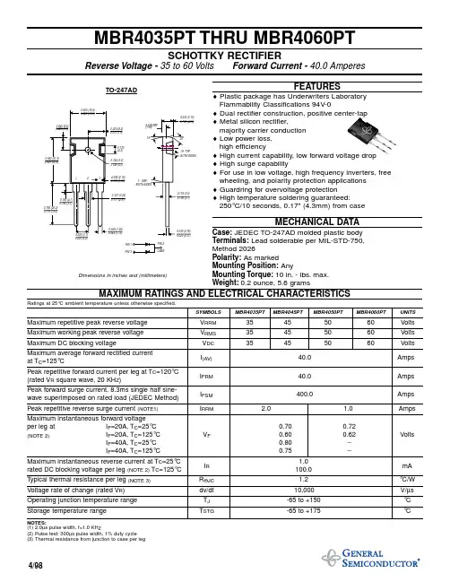
C 4.70 4.90
D 1.10 1.30
E 1.17 1.37
G 5.40 5.55
H 2.00 3.00
J 0.50 0.78
K 31.00 REF
L −−− 16.20
Q 4.00 4.10
S 17.80 18.20
U
4.00 REF
V
1.75 REF
STYLE 2: PIN 1. 2. 3. 4.
100
10
IR, REVERSE CURRENT (mA)
10 TC = 150°C
1 100
TC = 100°C
TC = 25°C
200
300
400
500
600
700
vF, INSTANTANEOUS FORWARD VOLTAGE (mV)
Figure 1. Typical Forward Voltage
“Typical” parameters which may be provided in SCILLC data sheets and/or specifications can and do vary in different applications and actual performance may vary over time. All
Instantaneous Reverse Current (Note 2) (Rated DC Voltage, TJ = 25°C) (Rated DC Voltage, TJ = 125°C)
Symbol Min
Typ
Max Unit
VF
V
−
0.53 0.70
−
0.46 0.60
−
0.64 0.80
to any products herein. SCILLC makes no warranty, representation or guarantee regarding the suitability of its products for any particular purpose, nor does SCILLC assume any liability
Shipping†
MBR4045PT
SOT−93
30 Units/Rail
MBR4045PTG
SOT−93 (Pb−Free)
30 Units/Rail
†For information on tape and reel specifications, including part orientation and tape sizes, please refer to our Tape and Reel Packaging Specifications Brochure, BRD8011/D.
Non−Repetitive Peak Surge Current (Surge Applied at Rated Load Conditions Halfwave, Single Phase, 60 Hz)
Peak Repetitive Reverse Current, (2.0 ms, 1.0 kHz)
Leads are Readily Solderable
• Lead Temperatures for Soldering Purposes: 260°C Max. for 10
Seconds
• ESD Rating: Human Body Model 3B
Machine Model C
*For additional information on our Pb−Free strategy and soldering details, please download the ON Semiconductor Soldering and Mounting Techniques Reference Manual, SOLDERRM/D.
10000 1000 100
1
30
25
20
15
DC
10
SQUARE WAVE
(VR = 45 V)
5
10 VR, REVERSE VOLTAGE (VOLTS)
0
100
100 110
120
130
140
150
160
TC, CASE TEMPERATURE (°C)
Figure 3. Typical Capacitance Per Leg
1
0.1
0.01
800
0
TC = 150°C TC = 100°C
TC = 25°C
10
20
30
40
50
VR, REVERSE VOLTAGE (VOLTS)
Figure 2. Typical Reverse Current
I F(AV), AVERAGE FORWARD CURRENT (AMPS)
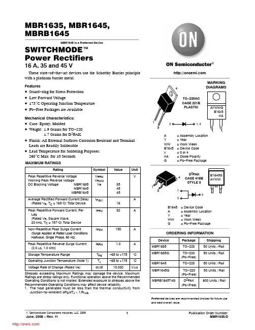
SCHOTTKY BARRIER RECTIFIER
40 AMPERES 45 VOLTS
1 2,4
3
SOT−93 CASE 340D
STYLE 2
MARKING DIAGRAM
AYWWG B4045
© Semiconductor Components Industries, LLC, 2006
Storage Temperature Range
Operating Junction Temperature (Note 1)
Peak Surge Junction Temperature (Forward Current Applied)
Voltage Rate of Change
VRRM VRWM
arising out of the application or use of any product or circuit, and specifically disclaims any and all liability, including without limitation special, consequential or incidental damages.
VR IF(AV)
IFRM
IFSM
IRRM
Tstg TJ TJ(pk)
dv/dt
45
20 40 40
400
2.0 −65 to +175 −65 to +175
175 10,000
V
A
A
A
A °C °C °C V/ms
Stresses exceeding Maximum Ratings may damage the device. Maximum Ratings are stress ratings only. Functional operation above the Recommended Operating Conditions is not implied. Extended exposure to stresses above the Recommended Operating Conditions may affect device reliability.
−
0.62 0.75
iR
mA
−
0.09
1.0
−
30
50
/
Байду номын сангаас
2
iF, INSTANTANEOUS FORWARD CURRENT (AMPS)
MBR4045PT
TYPICAL ELECTRICAL CHARACTERISTICS