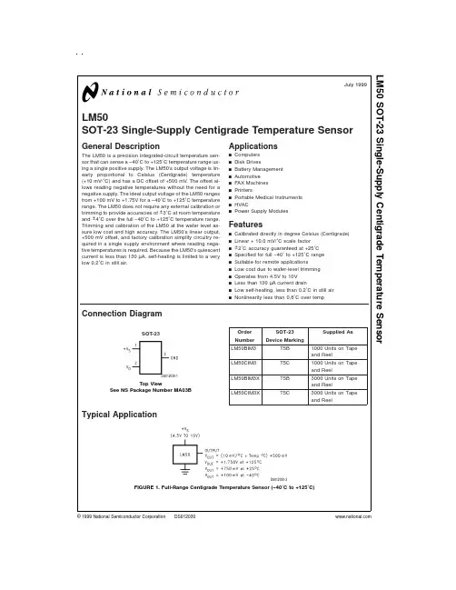
LM5035MH中文资料
- 格式:pdf
- 大小:932.74 KB
- 文档页数:28
LM5035PWM Controller with Integrated Half-Bridge and SyncFET DriversGeneral DescriptionThe LM5035Half-Bridge Controller/Gate Driver contains all of the features necessary to implement half-bridge topology power converters using voltage mode control with line volt-age feed-forward.The floating high-side gate driver is ca-pable of operating with supply voltages up to 105V.Both the high-side and low-side gate drivers are capable of 2A peak.An internal high voltage startup regulator is included,along with programmable line undervoltage lockout (UVLO)and overvoltage protection (OVP).The oscillator is programmed with a single resistor to frequencies up to 2MHz.The oscil-lator can also be synchronized to an external clock.A current sense input and a programmable timer provide cycle-by-cycle current limit and adjustable hiccup mode overload protection.Featuresn 105V /2A Half-Bridge Gate Driversn Synchronous Rectifier Control Outputs with Programmable Delaysn High Voltage (105V)Start-up Regulatorn Voltage mode Control with Line Feed-Forward and Volt •Second Limitingn Resistor Programmed,2MHz Capable Oscillator n Patent Pending Oscillator Synchronization n Programmable Line Under-Voltage Lockout n Line Over-Voltage Protectionn Internal Thermal Shutdown Protection n Adjustable Soft-Startn Versatile Dual Mode Over-Current Protection with Hiccup Delay Timern Cycle-by-Cycle Over-Current Protection n Direct Opto-coupler Interface n 5V Reference OutputPackagesn TSSOP-20EP (Thermally enhanced)n LLP-24(4mm x 5mm)Simplified Application Diagram20177501January 2006LM5035PWM Controller with Integrated Half-Bridge and SyncFET Drivers©2006National Semiconductor Corporation Connection DiagramsTop View2017750220-Lead TSSOP EPTop View20177503LLP-24PackageL M 5035 2Ordering InformationOrder Number Package Type NSC Package Drawing Supplied AsLM5035MH TSSOP-20EP MXA20A73Units per RailLM5035MHX TSSOP-20EP MXA20A2500Units on Tape and Reel LM5035SQ LLP-24SQA24B Available SoonLM5035SQX LLP-24SQA24B Available SoonPin DescriptionsTSSOP PIN LLPPIN Name Description Application Information123RAMP Modulator ramp signal An external RC circuit from VIN sets the ramp slope.This pinis discharged at the conclusion of every cycle by an internalFET.Discharge is initiated by either the internal clock or theVolt•Second clamp comparator.224UVLO Line Under-Voltage Lockout An external voltage divider from the power source sets theshutdown and standby comparator levels.When UVLOreaches the0.4V threshold the VCC and REF regulators areenabled.When UVLO reaches the1.25V threshold,the SS pinis released and the device enters the active mode.Hysteresisis set by an internal current sink that pulls23µA from theexternal resistor divider.32OVP Line Over-Voltage Protection An external voltage divider from the power source sets theshutdown levels.The threshold is1.25V.Hysteresis is set byan internal current source that sources23µA into the externalresistor divider.43COMP Input to the Pulse WidthModulator An external opto-coupler connected to the COMP pin sources current into an internal NPN current mirror.The PWM duty cycle is maximum with zero input current,while1mA reduces the duty cycle to zero.The current mirror improves the frequency response by reducing the AC voltage across the opto-coupler detector.54RT Oscillator Frequency Control andSync Clock Input.Normally biased at2V.An external resistor connected between RT and AGND sets the internal oscillator frequency.The internal oscillator can be synchronized to an external clock with a frequency higher than the free running frequency set by the RT resistor.65AGND Analog Ground Connect directly to Power Ground.76CS Current Sense input for currentlimit If CS exceeds0.25V the output pulse will be terminated, entering cycle-by-cycle current limit.An internal switch holds CS low for50ns after HO or LO switches high to blank leading edge transients.87SS Soft-start Input An internal55µA current source charges an external capacitorto set the soft-start rate.During a current limit restartsequence,the internal current source is reduced to1.2µA toincrease the delay before retry.98DLY Timing programming pin for theLO and HO to SR1and SR2outputs.An external resistor to ground sets the timing for thenon-overlap time of HO to SR1and LO to SR2.LM50353Pin Descriptions(Continued)TSSOP PIN LLP PIN Name DescriptionApplication Information109RESRestart TimerIf cycle-by-cycle current limit is exceeded during any cycle,a 22µA current is sourced to the RES pin capacitor.If the RES capacitor voltage reaches 2.5V,the soft-start capacitor will be fully discharged and then released with a pull-up current of 1.2µA.After the first output pulse at LO (when SS >COMP offset,typically 1V),the SS pin charging current will revert to 55µA.1111HB Boost voltage for the HO driverAn external diode is required from VCC to HB and an external capacitor is required from HS to HB to power the HO gate driver.1212HS Switch nodeConnection common to the transformer and both power switches.Provides a return path for the HO gate driver.1313HO High side gate drive output.Output of the high side PWM gate driver.Capable of sinking 2A peak current.1414LO Low side gate drive output.Output of the low side PWM gate driver.Capable of sinking 2A peak current.1515PGND Power GroundConnect directly to Analog Ground.1616VCCOutput of the high voltage start-up regulator.The VCC voltage is regulated to 7.6V.If an auxiliary winding raises the voltage on this pin above the regulation setpoint,the Start-up Regulator will shutdown,thus reducing the internal power dissipation.1717SR2Synchronous rectifier driver output.Control output of the synchronous FET gate.Capable of 0.5A peak current.1818SR1Synchronous rectifier driver output.Control output of the synchronous FET gate.Capable of 0.5A peak current.1919REF Output of 5V Reference Maximum output current is 20mA.Locally decoupled with a 0.1µF capacitor.2021VINInput voltage sourceInput to the Start-up Regulator.Operating input range is 13V to 100V with transient capability to 105V.For power sources outside of this range,the LM5035can be biased directly at VCC by an external regulator.EP EP EP Exposed Pad,underside of package No electrical contact.Connect to system ground plane for reduced thermal resistance.1NC No connection No electrical contact.10NC No connection No electrical contact.20NC No connection No electrical contact.22NCNo connectionNo electrical contact.L M 5035 4Absolute Maximum Ratings(Note1)If Military/Aerospace specified devices are required, please contact the National Semiconductor Sales Office/ Distributors for availability and specifications.VIN to GND-0.3V to105VHS to GND-1V to105VHB to GND-0.3V to118VHB to HS-0.3V to18V VCC to GND-0.3V to16V CS,RT,DLY to GND-0.3V to5.5V COMP Input Current10mAAll other inputs to GND-0.3V to7VESD Rating(Note4)Human Body Model2kVStorage Temperature Range-65˚C to150˚C Junction Temperature150˚COperating Ratings(Note1)VIN Voltage13V to105V External Voltage Applied to VCC8V to15V Operating Junction Temperature-40˚C to+125˚CElectrical Characteristics Specifications with standard typeface are for TJ=25˚C,and those with boldface type apply over full Operating Junction Temperature range.V VIN=48V,V VCC=10V externally applied,R RT=15.0kΩ,R DLY=27.4kΩ,V UVLO=3V,V OVP=0V unless otherwise stated.See(Note2)and(Note3).Symbol Parameter Conditions Min Typ Max Units Startup Regulator(VCC pin)V VCC VCC voltage I VCC=10mA7.37.67.9VI VCC(LIM)VCC current limit V VCC=7V2025mAV VCCUV VCC Under-voltage threshold(VCC increasing)VIN=VCC,∆V VCC from the regulationsetpoint0.20.1VVCC decreasing VCC–PGND 5.5 6.2 6.9V I VIN Startup regulator current VIN=90V,UVLO=0V3070µASupply current into VCC from external source Outputs&COMP open,V VCC=10V,Outputs Switching46mAVoltage Reference Regulator(REF pin)V REF REF Voltage I REF=0mA 4.855 5.15V REF Voltage Regulation I REF=0to10mA2550mVREF Current Limit REF=4.5V1520mAUnder-Voltage Lock Out and shutdown(UVLO pin)V UVLO Under-voltage threshold 1.212 1.25 1.288VI UVLO Hysteresis current UVLO pin sinking192327µAUnder-voltage Shutdown Threshold UVLO voltage falling0.3VUnder-voltage Standby EnableThresholdUVLO voltage rising0.4VOver-Voltage Protection(OVP pin)V OVP Over-Voltage threshold 1.212 1.25 1.288VI OVP Hysteresis current OVP pin sourcing192327µACurrent Sense Input(CS Pin)V CS Current Limit Threshold0.2280.250.272V CS delay to output CS from zero to1V.Time for HO and LOto fall to90%of VCC.Output load=0pF.80nsLeading edge blanking time at CS50nsCS sink impedance(clocked)Internal FET sink impedance3260ΩCurrent Limit Restart(RES Pin)V RES RES Threshold 2.4 2.5 2.6V Charge source current V RES=1.5V162228µADischarge sink current V RES=1V81216µALM50355Electrical Characteristics Specifications with standard typeface are for T J =25˚C,and those with boldfacetype apply over full Operating Junction Temperature range .V VIN =48V,V VCC =10V externally applied,R RT =15.0k Ω,R DLY =27.4k Ω,V UVLO =3V,V OVP =0V unless otherwise stated.See (Note 2)and (Note 3).(Continued)Symbol ParameterConditions Min Typ Max Units Soft-Start (SS Pin)I SSCharging current in normal operationV SS =0405570µA Charging current during a hiccup mode restartV SS =00.6 1.2 1.8µA Soft-stop Current SinkV SS =2.5V405570µAOscillator (RT Pin)F SW1Frequency 1(at HO,half oscillator frequency)R RT =15k Ω,T J =25˚C185200215kHzR RT =15k Ω,T J =-40˚C to 125˚C 180220F SW2Frequency 2(at HO,half oscillator frequency)R RT =5.49k Ω430500570kHz DC level2V Input Sync threshold2.533.4V PWM Controller (Comp Pin)Delay to output80ns V PWM-OSSS to RAMP offset 0.711.2V Minimum duty cycle SS =0V%Small signal impedanceI COMP =600µA,COMP current to PWM voltage5000ΩMain Output Drivers (HO and LO Pins)Output high voltage I OUT =50mA,V HB -V HO ,V VCC -V LO 0.50.25V Output low voltage I OUT =100mA 0.20.5V Rise time C LOAD =1nF 15ns Fall timeC LOAD =1nF13ns Deadtime,HO to LO,LO to HO V DLY =V REF ,I COMP =0mA 4570100ns Peak source current V HO,LO =0V,V VCC =10V 1.25A Peak sink currentV HO,LO =10V,V VCC =10V2AVoltage Feed-Forward (RAMP Pin)RAMP comparator thresholdCOMP current =02.42.52.6VSynchronous Rectifier Drivers (SR1,SR2)Output high voltage I OUT =10mA,V VCC -V SR1,V VCC -V SR20.250.1V Output low voltage I OUT =20mA (sink)0.080.2V Rise time C LOAD =1nF 40ns Fall timeC LOAD =1nF 20ns Peak source current V SR =0,V VCC =10V 0.5A Peak sink currentV SR =V VCC ,V VCC =10V0.5A T1Deadtime,SR1falling to HO rising,SR2falling to LO rising R DLY =10k 40ns R DLY =27.4k75100125ns R DLY =100k300ns T2Deadtime,HO falling to SR1rising,LO falling to SR2rising R DLY =10k 20ns R DLY =27.4k304565ns R DLY =100k140nsL M 5035 6LM5035Electrical Characteristics Specifications with standard typeface are for T=25˚C,and those with boldfaceJtype apply over full Operating Junction Temperature range.V VIN=48V,V VCC=10V externally applied,R RT=15.0kΩ,R DLY=27.4kΩ,V UVLO=3V,V OVP=0V unless otherwise stated.See(Note2)and(Note3).(Continued)Symbol Parameter Conditions Min Typ Max Units Thermal ShutdownT SD Shutdown temperature165˚C Hysteresis20˚C Thermal ResistanceθJA Junction to ambient,0LFPM AirTSSOP-20_EP package40˚C/W FlowθJC Junction to Case(EP)ThermalTSSOP-20_EP package4˚C/W resistanceNote1:Absolute Maximum Ratings are limits beyond which damage to the device may occur.Operating Ratings are conditions under which operation of the device is intended to be functional.For guaranteed specifications and test conditions,see the Electrical Characteristics.Note2:All limits are guaranteed.All electrical characteristics having room temperature limits are tested during production with T A=25˚C.All hot and cold limits are guaranteed by correlating the electrical characteristics to process and temperature variations and applying statistical process control.Note3:Typical specifications represent the most likely parametric norm at25˚C operationNote4:The human body model is a100pF capacitor discharged through a1.5kΩresistor into each pin.2kV for all pins except HB,HO and HS which are rated at1.5kV.7Typical Performance CharacteristicsV VCC and V REF vs V VINV VCC vs I VCC2017750520177506V REF vs I REFFrequency vs RT2017750720177508Oscillator Frequency vs Temperature Soft-Start &Stop Current vs Temperature2017750920177510L M 5035 8Typical Performance Characteristics(Continued)Effective Comp Input ImpedanceR DLY vs Deadtime2017751120177512SR "T1"Parameter vs Temperature SR "T2"Parameter vs Temperature2017751320177514LM50359Block Diagram20177504FIGURE 1.L M 5035 10Functional DescriptionThe LM5035PWM controller contains all of the features necessary to implement half-bridge voltage-mode controlled power converters.The LM5035provides two gate driver outputs to directly drive the primary side power MOSFETs and two signal level outputs to control secondary synchro-nous rectifiers through an isolation interface.Secondary side drivers,such as the LM5110,are typically used to provide the necessary gate drive current to control the sync MOS-FETs.Synchronous rectification allows higher conversion efficiency and greater power density than conventional PN or Schottky rectifier techniques.The LM5035can be configured to operate with bias voltages ranging from8V to105V. Additional features include line under-voltage lockout,cycle-by-cycle current limit,voltage feed-forward compensation, hiccup mode fault protection with adjustable delays,soft-start,a2MHz capable oscillator with synchronization capa-bility,precision reference,thermal shutdown and program-mable volt•second clamping.These features simplify the design of voltage-mode half-bridge DC-DC power convert-ers.The Functional Block Diagram is shown in Figure1. High-Voltage Start-up RegulatorThe LM5035contains an internal high voltage start-up regu-lator that allows the input pin(VIN)to be connected directly to a nominal48VDC input voltage.The regulator input can withstand transients up to105V.The regulator output at VCC (7.6V)is internally current limited to25mA typical.When the UVLO pin potential is greater than0.4V,the VCC regulator is enabled to charge an external capacitor connected to the VCC pin.The VCC regulator provides power to the voltage reference(REF)and the output drivers(LO,SR1and SR2). When the voltage on the VCC pin exceeds the UVLO thresh-old of7.6V,the internal voltage reference(REF)reaches its regulation setpoint of5V and the UVLO voltage is greater than1.25V,the controller outputs are enabled.The value of the VCC capacitor depends on the total system design,and its start-up characteristics.The recommended range of val-ues for the VCC capacitor is0.1µF to100µF.The VCC under-voltage comparator threshold is lowered to 6.2V(typical)after VCC reaches the regulation set-point.If VCC falls below this value,the outputs are disabled,and the soft-start capacitor is discharged.If VCC increases above 7.6V,the outputs will be enabled and a soft-start sequence will commence.The internal power dissipation of the LM5035can be re-duced by powering VCC from an external supply.In typical applications,an auxiliary transformer winding is connected through a diode to the VCC pin.This winding must raise the VCC voltage above8.3V to shut off the internal start-up regulator.Powering VCC from an auxiliary winding improves efficiency while reducing the controller’s power dissipation. The under-voltage comparator circuit will still function in this mode,requiring that VCC never falls below6.2V during the start-up sequence.During a fault mode,when the converter auxiliary winding is inactive,external current draw on the VCC line should be limited such that the power dissipated in the start-up regula-tor does not exceed the maximum power dissipation of the IC package.An external DC bias voltage can be used instead of the internal regulator by connecting the external bias voltage to both the VCC and the VIN pins.The external bias must be greater than8.3V to exceed the VCC UVLO threshold andless than the VCC maximum operating voltage rating(15V).Line Under-Voltage DetectorThe LM5035contains a dual level Under-Voltage Lockout (UVLO)circuit.When the UVLO pin voltage is below0.4V,the controller is in a low current shutdown mode.When theUVLO pin voltage is greater than0.4V but less than1.25V,the controller is in standby mode.In standby mode the VCCand REF bias regulators are active while the controller out-puts are disabled.When the VCC and REF outputs exceedthe VCC and REF under-voltage thresholds and the UVLOpin voltage is greater than1.25V,the outputs are enabledand normal operation begins.An external set-point voltagedivider from VIN to GND can be used to set the minimum operating voltage of the converter.The divider must be designed such that the voltage at the UVLO pin will be greater than1.25V when VIN enters the desired operating range.UVLO hysteresis is accomplished with an internal23uA current sink that is switched on or off into the imped-ance of the set-point divider.When the UVLO threshold is exceeded,the current sink is deactivated to quickly raise the voltage at the UVLO pin.When the UVLO pin voltage fallsbelow the1.25V threshold,the current sink is enabled caus-ing the voltage at the UVLO pin to quickly fall.The hysteresisof the0.4V shutdown comparator is internally fixed at100mV.The UVLO pin can also be used to implement various re-mote enable/disable functions.Turning off a converter byforcing the UVLO pin to the standby condition provides a controlled soft-stop.See the Soft Start section for more details.Line Over Voltage/Load OverVoltage/Remote ThermalProtectionThe LM5035provides a multipurpose OVP pin that supports several fault protection functions.When the OVP pin voltage exceeds1.25V,the controller is held in standby mode which immediately halts the PWM pulses at the HO and LO pins.In standby mode,the VCC and REF bias regulators are activewhile the controller outputs are disabled.When the OVP pin voltage falls below the1.25V OVP threshold,the outputs are enabled and normal soft-start sequence begins.Hysteresisis accomplished with an internal23µA current source that is switched on or off into the impedance of the OVP pin set-point divider.When the OVP threshold is exceeded,thecurrent source is enabled to quickly raise the voltage at theOVP pin.When the OVP pin voltage falls below the1.25V threshold,the current source is disabled causing the voltageat the OVP pin to quickly fall.Several examples of the use of this pin are provided in the Application Information section.ReferenceThe REF pin is the output of a5V linear regulator that can beused to bias an opto-coupler transistor and external house-keeping circuits.The regulator output is internally currentlimited to20mA(typical).LM5035Cycle-by-Cycle Current LimitThe CS pin is driven by a signal representative of the trans-former primary current.If the voltage sensed at CS pin exceeds 0.25V,the current sense comparator terminates the HO or LO output driver pulse.If the high current condition persists,the controller operates in a cycle-by-cycle current limit mode with duty cycle determined by the current sense comparator instead of the PWM comparator.Cycle-by-cycle current limiting may trigger the hiccup mode restart cycle depending on the configuration of the RES pin (see below).A small R-C filter connect to the CS pin and located near the controller is recommended to suppress noise.An internal 32ΩMOSFET connected to the CS input discharges the external current sense filter capacitor at the conclusion of every cycle.The discharge MOSFET remains on for an additional 50ns after the HO or LO driver switches high to blank leading edge transients in the current sensing circuit.Discharging the CS pin filter each cycle and blanking leading edge spikes reduces the filtering requirements and improves the current sense response time.The current sense comparator is very fast and responds to short duration noise yout considerations are criti-cal for the current sense filter and sense resistor.The ca-pacitor associated with the CS filter must be placed very close to the device and connected directly to the CS and AGND pins.If a current sense transformer is used,both leads of the transformer secondary should be routed to the filter network,which should be located close to the IC.If a sense resistor located in the source of the main MOSFET switch is used for current sensing,a low inductance type of resistor is required.When designing with a current sense resistor,all of the noise sensitive low power ground connec-tions should be connected together near the AGND pin,and a single connection should be made to the power ground (sense resistor ground point).Overload Protection TimerThe LM5035provides a current limit restart timer to disable the outputs and force a delayed restart (hiccup mode)if a current limit condition is repeatedly sensed.The number of cycle-by-cycle current limit events required to trigger the restart is programmable by the external capacitor at the RES pin.During each PWM cycle,the LM5035either sources or sinks current from the RES pin capacitor.If no current limit is detected during a cycle,an 12µA discharge current sink is enabled to pull the RES pin to ground.If a current limit is detected,the 12µA sink current is disabled and a 22µAcurrent source causes the voltage at the RES pin to gradu-ally increase.The LM5035protects the converter with cycle-by-cycle current limiting while the voltage at RES pin in-creases.If the RES voltage reaches the 2.5V threshold,the following restart sequence occurs (also see Figure 2):•The RES capacitor and SS capacitors are fully dis-charged•The soft-start current source is reduced from 55µA to 1µA •The SS capacitor voltage slowly increases.When the SS voltage reaches )1V,the PWM comparator will produce the first narrow output pulse.After the first pulse occurs,the SS source current reverts to the normal 55µA level.The SS voltage increases at its normal rate,gradually increasing the duty cycle of the output drivers•If the overload condition persists after restart,cycle-by-cycle current limiting will begin to increase the voltage on the RES capacitor again,repeating the hiccup mode sequence•If the overload condition no longer exists after restart,the RES pin will be held at ground by the 12µA current sink and normal operation resumes The overload timer function is very versatile and can be configured for the following modes of protection:1.Cycle-by-cycle only:The hiccup mode can be com-pletely disabled by connecting a zero to 50k Ωresistor from the RES pin to AGND.In this configuration,the cycle-by-cycle protection will limit the output current indefinitely and no hiccup sequences will occur.2.Hiccup only:The timer can be configured for immediate activation of a hiccup sequence upon detection of an over-load by leaving the RES pin open circuit.3.Delayed Hiccup:Connecting a capacitor to the RES pin provides a programmed interval of cycle-by-cycle limiting before initiating a hiccup mode restart,as previously de-scribed.The dual advantages of this configuration are that a short term overload will not cause a hiccup mode restart but during extended overload conditions,the average dissipa-tion of the power converter will be very low.4.Externally Controlled Hiccup:The RES pin can also be used as an input.By externally driving the pin to a level greater than the 2.5V hiccup threshold,the controller will be forced into the delayed restart sequence.For example,the external trigger for a delayed restart sequence could come from an over-temperature protection circuit or an output over-voltage sensor.L M 5035Overload Protection Timer(Continued)20177515FIGURE2.Current Limit Restart Circuit20177516FIGURE3.Current Limit Restart Timing LM5035Overload Protection Timer(Continued)Soft-StartThe soft-start circuit allows the regulator to gradually reach a steady state operating point,thereby reducing start-up stresses and current surges.When bias is supplied to the LM5035,the SS pin capacitor is discharged by an internal MOSFET.When the UVLO,VCC and REF pins reach their operating thresholds,the SS capacitor is released and charged with a 55µA current source.The PWM comparator control voltage is clamped to the SS pin voltage by an internal amplifier.When the PWM comparator input reaches 1V,output pulses commence with slowly increasing duty cycle.The voltage at the SS pin eventually increases to 5V,while the voltage at the PWM comparator increases to the value required for regulation as determined by the voltage feedback loop.One method to shutdown the regulator is to ground the SS pin.This forces the internal PWM control signal to ground,reducing the output duty cycle quickly to zero.Releasing the SS pin begins a soft-start cycle and normal operation re-sumes.A second shutdown method is discussed in the UVLO section.Soft-StopIf the UVLO pin voltage falls below the 1.25V standby thresh-old but above the 0.4V shutdown threshold,the 55µA SS pin source current is disabled and a 55µA sink current dis-charges the soft-start capacitor.As SS voltage falls and clamps the PWM comparator input,the PWM duty cycle will gradually fall to zero.The soft-stop feature produces a gradual reduction of the power converter output voltage.This soft-stop method of turning off the converter reduces energy in the output capacitor before control of the main and syn-chronous rectification MOSFETs is disabled.The PWM pulses may cease before the SS voltage reduces the duty cycle if the VCC or REF voltage drops below the respective under-voltage thresholds during the soft-stop process.PWM ComparatorThe pulse width modulation (PWM)comparator compares the voltage ramp signal at the RAMP pin to the loop error signal.This comparator is optimized for speed in order toachieve minimum controllable duty cycles.The loop error signal is received from the external feedback and isolation circuit is in the form of a control current into the COMP pin.The COMP pin current is internally mirrored by a matched pair of NPN transistors which sink current through a 5k Ωresistor connected to the 5V reference.The resulting control voltage passes through a 1V level shift before being applied to the PWM comparator.An opto-coupler detector can be connected between the REF pin and the COMP pin.Because the COMP pin is controlled by a current input,the potential difference across the optocoupler detector is nearly constant.The bandwidth limiting phase delay which is normally introduced by the significant capacitance of the opto-coupler is thereby greatly reduced.Higher loop bandwidths can be realized since the bandwidth-limiting pole associated with the opto-coupler is now at a much higher frequency.The PWM comparator polarity is configured such that with no current into the COMP pin,the controller produces the maximum duty cycle at the main gate driver outputs,HO and LO.Feed-Forward Ramp and Volt •Second ClampAn external resistor (R FF )and capacitor (C FF )connected to VIN,AGND,and the RAMP pin are required to create the PWM ramp signal.The slope of the signal at RAMP will vary in proportion to the input line voltage.This varying slope provides line feed-forward information necessary to improve line transient response with voltage mode control.The RAMP signal is compared to the error signal by the pulse width modulator comparator to control the duty cycle of the HO and LO outputs.With a constant error signal,the on-time (T ON )varies inversely with the input voltage (VIN)to stabilize the Volt •Second product of the transformer primary signal.The power path gain of conventional voltage-mode pulse width modulators (oscillator generated ramp)varies directly with input voltage.The use of a line generated ramp (input voltage feed-forward)nearly eliminates this gain variation.As a result,the feedback loop is only required to make very small corrections for large changes in input voltage.In addition to the PWM comparator,a Volt •Second Clamp comparator also monitors the RAMP pin.If the ramp ampli-20177517FIGURE 4.Optocoupler to COMP InterfaceL M 5035。