IO-Link技术规范简介
- 格式:pdf
- 大小:514.32 KB
- 文档页数:13

IO-Link手册第三版请访问:/CN目录引言第4页第1部分:IO-Link简介第5页◆老派传感器第5页◆微型开关量传感器驱动第5页◆I O-Link:开放式低成本传感器接口第5页◆I O-Link节点第5页◆I O-Link系统第6页◆I O-Link接口在IEC 61131-9中被标准化为SDCI第6页◆物理层IO-Link标准化接口第6页◆物理层电气规范第7页◆自动化体系中的IO-Link第7页◆I O-Link:实现智能传感器第7页◆工业传感器生态系统第8页第6部分:提高系统性能第24页◆散热第24页◆测试A第24页◆测试B第24页◆测试C第24页◆热性能第24页◆分立解决方案第25页◆集成解决方案第25页◆选择TVS二极管第25页◆I O-Link保护电路第25页◆65 V(绝对最大值)如何帮助提供保护(对比40 V)第25页◆65 V绝对最大值的保护优势第25页◆小结第26页◆I O-Link信号摆率如何影响IO-Link电缆辐射?第26页引言当今的无风扇可编程逻辑控制器(PLC)和IO-Link®网关系统须消耗大量功率,具体取决于I/O配置(IO-Link、数字输入/输出、模拟输入/输出)。
随着这些PLC演变成新的工业4.0智能工厂,我们必须深谋远虑,实现更智能、更快速、更低功耗的解决方案。
这场革命的核心是一项名为“IO-Link”的新技术,能帮助实现灵活制造,从而改善工厂吞吐量,提高运营效率。
这项激动人心的新技术正使传统传感器转变为智能传感器。
ADI公司提供一系列先进的工厂自动化解决方案,并通过我们的IO-Link技术产品系列进一步改进性能,为实现工业4.0铺路架桥。
MAX22513是该产品系列的最新成员,这是一款微型双通道IO-Link收发器,集成了浪涌保护和DC-DC转换器,可减少热耗散并提高工厂车间传感器的稳定性。
为了帮助我们的客户缩短上市时间,我们与来自IO-Link联盟的软件协议栈供应商合作开发了一系列经过全面验证和测试的参考设计,本手册对此进行了详细说明。

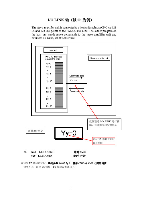
I/O LINK轴(以Oi为例)例:X20 1.0.1.OC02I 此时x=20Y20 1.0.1.OC02O 此时y=20在设定I/O模块的同时,确定参数960#3为0 确保CNC与AMP之间的通信设置不当出现54#报警I/O模块没有连接上硬件接线:B 放大器 JA35 EX IO 中接线当不使用外部减速挡块时,默认设置为0,采用无挡块回零方式参数设置:与普通的伺服电机具有相同的伺服设定急停互锁+超程 —超程初始化信号:信号相对简单,进行简单动作的控制这里的Y地址是CNC--→AMP 控制AMP执行指定的动作作用相当于平时所用的G地址信号这里的X地址是AMP--→CNC AMP反馈给CNC的信息目前AMP处在何种状态作用相当于平时所用的F地址信号操作:IO LINK控制方式由信号DRC的状态决定在操作时两种接口可以切换,但是由于两种接口的时序不同,改变时梯形图也要相应改变,通常上电时不要进行切换。
IO LINK运行方式大部分操作都是在JOG 和AUTO 两种方式下进行 它的方式可以独立于系统本身(HOST )方式的影响 通常与HOST 的工作方式串在一起 保持一致Y22 Y23Y26#7 #6 #5 #4 #3 #2 #1 #0|参数的保存:在参数画面的操作与常规的参数输入/输出相同1把参数以程序的形式,转到我们平时可以看到的程序画面2 把参数传到存储卡(960#1设1)操作如图所示:1.)选择要传出的参数画面2.按下软键[<OPRT>]按下菜单扩展键[ ]3.按下[READ]键但是它的输入/输出是AMP (B放大器) 与CNC MEMORY 之间。
当AMP-→CNC [ READ ]CNC-→AMP [ WRITE ]关于存储的程序号:在8760中设定所传出参数的程序号范围当8760中设定2000时传出的参数的程序号为2010 (即:2000+N x10 )注:N为放大器组号当该程序号已存在时设定3201#2 REP 是否将该程序覆盖。
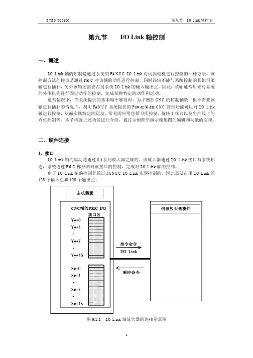
第九节I/O Link轴控制一、概述I/O Link轴的控制是通过系统的FANUC I/O Link对伺服电机进行控制的一种方法。
该控制方法的特点是通过PMC对该轴的动作进行控制,同时该轴不能与系统控制的其他伺服轴进行插补,另外该轴还需要占用系统I/O Link的输入输出点。
因此,该轴通常用来对系统的外围机构进行固定动作的控制,完成某种特定的动作和运动。
通常情况下,当系统提供的基本轴不够用时,为了增加CNC的控制轴数,但不需要该轴进行插补的情况下,利用FANUC系统提供的Power Mate CNC管理功能可以对I/O Link 轴进行控制,从而实现特定的运动。
常见的应用包括刀库控制、旋转工作台以及生产线上的点位控制等。
本节将就上述功能进行介绍,通过示例程序演示梯形图的编辑和功能的实现。
二、硬件连接1.接口I/O Link轴的驱动是通过βi系列放大器完成的。
该放大器通过I/O Link接口与系统相连,系统通过PMC梯形图对该接口的控制,完成对I/O Link轴的控制。
由于I/O Link轴的控制是通过FANUC I/O Link实现控制的,因此需要占用I/O Link的128个输入点和128个输出点。
图9.2.1 I/O Link轴放大器的连接示意图2.地址分配如上图2.1.1所示,当使用I/O Link作为系统与放大器之间的通讯时,需要设定通讯地址。
通过该通道完成通讯。
由于通过I/O Link对该轴的进行控制,因此该轴的地址分配符合系统对I/O地址分配的原则。
对于系统侧而言,进行I/O模块的地址分配时,需要分配一个16字节大小的模块。
例如:OC02I或者OC02O。
对于本书中关于I/O Link轴设定方面的地址表示方法,通常表示为:如果从Y50开始分配,则在Y50进行分配:1.0.1.OC02O ,此时y=50。
也就是说“y”表示开始的地址值。
在本节后面的叙述中,都将以X50与Y50作为起始地址进行叙述,但是在实际使用当中可以对其进行修改。

IO-Link模块安全操作保养规定IO-Link是一种数字通信协议,可以实现传感器、执行器与控制器之间的通信。
IO-Link模块是IO-Link通信的基本组成部分,广泛应用于自动化设备、机械、仪器仪表等领域。
为了确保IO-Link模块的安全操作和长期正常运行,我们制定了以下操作保养规定。
1. 操作规定1.1 上电与断电操作•上电前,先检查IO-Link模块的电源线路是否连接正确,电源线路的标志是否清晰。
•上电时,先连接好通信线路,再连接电源线路,注意电源电压的合适性。
•断电时,先断开电源线路,再断开通信线路。
1.2 其他操作•在操作IO-Link模块前,先了解模块的性能参数和功能特点。
•操作时,不要使用金属工具和手指直接触摸模块,以免产生静电。
•不要在模块上磨擦或刮擦,避免刮伤表面。
•不要非正常操作模块,避免对模块造成损坏。
•操作完毕后,及时清理IO-Link模块,避免灰尘和杂物对模块的影响。
2. 保养规定2.1 清洁保养•定期用干净软布擦拭IO-Link模块,保持外部干净卫生。
•不要使用酸、碱等腐蚀性的溶剂来清洁模块,以免损坏模块表面。
2.2 维护保养•认真保护IO-Link通信标志,避免被撕掉或涂污。
•定期检查IO-Link模块的固定螺丝,并及时拧紧,避免松动。
•定期检查IO-Link模块内部的电子元件的连接和接插情况,确保连接牢固。
•定期检查IO-Link模块的线路和元件,确保正常工作和使用寿命。
•不要将IO-Link模块置于高温、潮湿、尘土多、化学品等异常环境中,以免影响模块的正常运行。
3. 注意事项•在操作IO-Link模块时,遵守产品说明书和技术规范标准,确保安全、可靠地运行。
•严格禁止非授权人员擅自拆卸IO-Link模块内部任何部件或组件,避免对模块造成损伤或人员伤害。
•在储存IO-Link模块时,应放置在干燥、通风、温度适宜的仓库中,避免受潮、受热或者过度振动损坏模块。
•超出IO-Link模块的功能规范范围,是非法操作行为,也是非常危险的行为,请勿尝试。

IO-Link 通信协议及其在工业物联网应用领域的用途本文将简要介绍IO-Link 通信协议及其在工业物联网应用领域的用途。
然后,本文将介绍Maxim Integrated MAX14827A 收发器,以示范如何针对各种工业检测和安全应用来部署经济高效的工业物联网边缘层节点。
IO-Link 概述IO-Link (IEC 61131-9) 是一种点对点串行通信协议,针对包含传感器、执行器和低功耗微处理器的智能边缘层节点进行了优化。
它的基本形式是三线连接,可以切换模拟和数字信号(8 位、12 位和16 位)。
它简明、智能、高效且可配置,并具有提供更多信息和控制的能力,因而得到了广泛的工业支持。
在典型的工业安装中,多个IO-Link 主站可操作执行器,并从传感器收集数据;它们还能够动态地重新配置传感器和执行器。
可编程逻辑控制器(PLC) 可能包含多个IO-Link 主站,每个主站连接到一个或多个器件。
PLC 本身是局域网(例如现场总线)上的节点。
诸如工业以太网之类的更高速网络,在PLC 集线器和更高的企业或云级别之间传输数据和命令。
IO-Link 标准引脚分配根据M5、M8、M12 的圆形外形尺寸,将数据链路和电源连接组合在单个连接器中:其中M12 最为常用。
传感器连接器有四个引脚,执行器有五个引脚:IO-Link 主站器件通常有五引脚插座。
该标准定义了两个端口类,即端口A 和端口B:引脚1、3 和4 在两个端口类中执行相同的功能。
在端口A 中,引脚2 和5 未指定具体功能,但制造商通常使用引脚2 作为附加数字通信通道。
在端口 B 中,引脚 2 和 5 为具有较大需求的器件提供额外电源。
IO-Link 规范具有后向兼容性,并能够适应旧有设备。
主站可以使用标准输入输出(SIO) 功能来操作这些器件,将C/Q 串行链路转化为分立式数字I/O 端口。
SIO 还支持IO-link 传感器与传统输入模块结合使用。
IO-LINK的设定一实习目的了解和掌握FANUC的IO单元和系统之间的硬件连线,掌握IO-LINK的软件设定,以及在调试或维修工作中进行信号强制的方法。
二 IO-LINK的相关概念对于对连接到IO单元的信号地址的定义,系统需要先确定每个IO单元在串行回路中的物理位置。
然后确定每个IO单元Xm/Yn的m、n单元的起始地址(当每个IO单元的起始地址定义好后,对应于IO单元上每个物理输入点就都具备了确定的地址)。
物理地址的表示含义:组、座、槽组:系统的JDIA到IO单元的JD1B、IO单元的JD1A到下一单元的JD1B,形成串行通讯。
每个从属的IO单元就一个组,组的顺序以离系统的连线顺序而依次定义为0、1···· 、n(n=15)座:对于特殊模块IO-UNIT来说,在一个组中可以连接有扩展单元。
因此,对于基本模块和扩展模块可以分别定义成0座、1座,对于其他的通用IO模块来说都是默认的0座。
槽:对于特殊模块IO-UNIT来说,在每个座上都有相应的模块插槽,定义时要分别以安装的插槽顺序1、2···、10来定义每个插槽的物理位置。
如图确定了IO 单元的物理连接顺序后,其相应的组号就确定了,然后可以通过系统的IO-LINK 的设定画面来定义每个IO 单元所对应的起始地址m/n 。
三:具体实习操作:1) 查看实际系统和外部IO 单元的连接顺序,确定每个IO 单元的组号。
2) 检查系统画面所诊断出的IO 单元的数量和实际的单元的数量是否一致。
操作:[SYSTEM ]→[PMC]→[PMCDGN]→[IOCHCK]→[IOLNK]3) 确定每个每个IO 单元的起始地址后,进入IO-LINK 的设定画面进行设定。
确定数量0座1槽2槽第0组第1组第2组操作:[SYSTEM]→[PMC]→[PMCPRM]→[SETTING]设定此参数为1,然后进入IO-LINK设定画面。
SIMATICET 200SP通信模块IO-Link Master CM4xIO-Link (6ES7137-6BD00-0BA0)设备手册法律资讯警告提示系统为了您的人身安全以及避免财产损失,必须注意本手册中的提示。
人身安全的提示用一个警告三角表示,仅与财产损失有关的提示不带警告三角。
警告提示根据危险等级由高到低如下表示。
危险表示如果不采取相应的小心措施,将会导致死亡或者严重的人身伤害。
警告表示如果不采取相应的小心措施,可能导致死亡或者严重的人身伤害。
小心表示如果不采取相应的小心措施,可能导致轻微的人身伤害。
注意表示如果不采取相应的小心措施,可能导致财产损失。
当出现多个危险等级的情况下,每次总是使用最高等级的警告提示。
如果在某个警告提示中带有警告可能导致人身伤害的警告三角,则可能在该警告提示中另外还附带有可能导致财产损失的警告。
合格的专业人员本文件所属的产品/系统只允许由符合各项工作要求的合格人员进行操作。
其操作必须遵照各自附带的文件说明,特别是其中的安全及警告提示。
由于具备相关培训及经验,合格人员可以察觉本产品/系统的风险,并避免可能的危险。
按规定使用 Siemens 产品请注意下列说明:警告Siemens 产品只允许用于目录和相关技术文件中规定的使用情况。
如果要使用其他公司的产品和组件,必须得到 Siemens 推荐和允许。
正确的运输、储存、组装、装配、安装、调试、操作和维护是产品安全、正常运行的前提。
必须保证允许的环境条件。
必须注意相关文件中的提示。
商标所有带有标记符号 ® 的都是 Siemens AG 的注册商标。
本印刷品中的其他符号可能是一些其他商标。
若第三方出于自身目的使用这些商标,将侵害其所有者的权利。
责任免除我们已对印刷品中所述内容与硬件和软件的一致性作过检查。
然而不排除存在偏差的可能性,因此我们不保证印刷品中所述内容与硬件和软件完全一致。
印刷品中的数据都按规定经过检测,必要的修正值包含在下一版本中。
BNI IOL-309-002-Z019 IO-Link 1.1 sensor/actuator hubwith extension portUser's GuideBalluff Network Interface / IO-Link BNI IOL-309-002-Z019Contents1User Instructions 4 1.1.About This Manual 4 1.2.Structure of the Manual 4 1.3.Typographical Conventions 4Enumerations 4 Actions 4 Syntax 4 Cross-references 4 1.4.Symbols 4 1.5.Abbreviations 4 1.6.Differing views 4 2Safety 5 2.1.Intended use 5 2.2.Installation and Startup 5 2.3.General Safety Notes 5 2.4.Resistance to Aggressive Substances 5Dangerous voltage 5 3First Steps 6 3.1.Connection Overview 6 3.2.Mechanical Connection 7 3.3.Electrical Connection 7Functional ground 7 IO-Link connection 7 Connecting the sensor hub 8 Module variants 8 Sensor/actuator interface 8 Extension port 8 4General Configuration 9 4.1.Extension port 9Extension port configuration 55hex9 Setting the serial number 54hex9 5Configuration: "Extension Off" 10 5.1.IO-Link Data 10 5.2.Process Data Input 10 5.3.Process Data Ouput 10 5.4.Parameter Data/Demand Data 11Parameter Data/Demand Data 11 Inversion of the inputs 40hex12 Configuration In-Outputs 41hex12 Safe state of Outputs 42hex12 Voltage monitoring 44hex14 Monitoring the outputs 45hex14 6Configuration: extended with BNI IOL-102-002-Z019 15 6.1.IO-Link Data 15 6.2.Process Data/Input Data 15 6.3.Process Data/ Output Data 16 6.4.Parameter Data/Demand Data 17Parameter Data/Demand Data 17 Inversion of the inputs 40hex18 Configuration In-/Output 41hex18 Safe state of Outputs 42hex19 Safe state of the outputs on Pin 4 42hex19 Voltage monitoring 44hex20 Monitoring the outputs 45hex20 Setting the serial number 54hex207Diagnosis 21 7.1.Error Codes/ Errors 21 7.2.Events 21 8IO-Link Functions 22 8.1.IO-Link Version 1.0 / 1.1 22 8.2.Data Storage 22 8.3.Block Configuration 22 8.4.Resetting to Factory Settings 22 9Technical Data 23 9.1.Dimensions 23 9.2.Mechanical Data 23 9.3.Electrical Data 23 9.4.Operating conditions 23 10Function Indicators 24 10.1.Function Indicators 24LED-Indicators module status 24 Digital LED indicators for inputs/outputs 25 Extension port 25 11Appendix 26 11.1.Type Code 26 11.2.Ordering Information 26Balluff Network Interface / IO-Link BNI IOL-309-002-Z019 1User Instructions1.1.About ThisManual This manual describes the Balluff IO-Link I/O module, also called a sensor/actuator hub. The IO-Link protocol is used to link to the higher-level master module.In terms of function, this compact, cost-effective module is similar to a passive splitter box; it records digital and analog sensor signals and transmits them over the IO-Link interface. It passes control signals coming over IO-Link to the connected actuators.1.2.Structure of theManual The manual is organized so that the sections build on one another. Chapter 2: Basic Safety Information.……..1.3.TypographicalConventionsThe following typographical conventions are used in this manual.Enumerations Enumerations are shown as a list with an dash.−Entry 1.−Entry 2.Actions Action instructions are indicated by a preceding triangle. The result of an action is indicated by an arrow.➢Action instruction 1.Action result.➢Action instruction 2.Syntax Numbers:Decimal numbers are shown without additional indicators (e.g. 123).Hexadecimal numbers are shown with the additional indicator hex (e.g. 00hex).Cross-references Cross-references indicate where additional information on the topic can be found.1.4.Symbols Attention!This symbol indicates a safety instruction that must be followed without exceptionNoteThis symbol indicates general notes.1.5. Abbreviations BNIDPPI/O portEMCFEIOLLSBMSBSPDU Balluff Network Interface Direct Parameter Page Digital input/output port Electromagnetic compatibility Function EarthIO-LinkLeast Significant BitMost Significant BitService Protocol Data Unit1.6.Differing views Product views and images in this manual may differ from the product described. They areintended to serve only as illustrations.2Safety2.1.Intended use The BNI IOL-… acts as a decentralized input/output sensor module, which is connected to ahigher-level IO-Link master module through an IO-Link interface.2.2.Installation andStartup Attention!Installation and startup must only be carried out by trained technical personnel. Qualified personnel are people who are familiar with installation and operation of the product and have the necessary qualifications for these tasks. Any damage resulting from unauthorized tampering or improper use voids the manufacturer's guarantee and warranty. The operator must ensure that appropriate safety and accident prevention regulations are observed.2.3.General SafetyNotes Commissioning and inspectionBefore commissioning, carefully read the user's guide.The system must not be used in applications in which the safety of persons is dependent upon proper functioning of the device.Authorized personnelInstallation and startup must only be carried out by trained technical personnel.Intended useWarranty and liability claims against the manufacturer are rendered void by: −Unauthorized tampering−Improper use−Use, installation or handling contrary to the instructions provided in this user's guideObligations of the operating companyThe device is a piece of equipment in accordance with EMC Class A. This device can produce RF noise. The operator must take appropriate precautionary measures. The device may only be used with an approved power supply. Use only approved cables. MalfunctionsIn the event of defects and device malfunctions that cannot be rectified, the device must be taken out of operation and protected against unauthorized use.Intended use is ensured only when the housing is fully installed.2.4.Resistance toAggressiveSubstances Attention!The BNI modules always have good chemical and oil resistance. When used in aggressive media (such as chemicals, oils, lubricants and coolants, each in a high concentration (i.e. too little water content)), the material must first be checked for resistance in the particular application. No defect claims may be asserted in the event of a failure or damage to the BNI modules caused by such aggressive media.Dangerous voltage Attention!Before maintenance, disconnect the device from the power supply.NoteIn the interests of product improvement, Balluff GmbH reserves the right to change the technical data of the product and the content of this manualat any time without notice.Balluff Network Interface / IO-Link BNI IOL-309-002-Z0193 First Steps3.1. ConnectionOverviewFigure 3-1: Connection overview BNI IOL-309-002-Z0191 Ground connection2 Mounting hole3 Status LED: communication4 Label5 Port 16 Port 37 Port 58 Port 7, extension port9 Pin/Port LED: signal status 10 Port 6 11 Port 4 12 Port 2 13 Port 0 14 IO-Link interface12 345678 2910111213143 First Steps3.2.MechanicalConnectionThe BNI IOL modules are attached using 2 max. M4 screws and 2 washers.3.3.ElectricalConnection The BNI IOL-309-002-Z019 modules do not require a separate supply voltage connection. Supply voltage is provided via the IO-Link interface and the higher-level IO-Link master module.FunctionalgroundThe modules are equipped with a ground connection.Figure 3-3: BNI ground connection IOL-309...➢Connect the sensor hub module to the ground connection.NoteThe functional ground connection from the housing to the machine must havelow-impedance and be kept as short as possible.IO-LinkconnectionThe IO-Link connection is established via an M12 connector (A-coded, male).IO-Link (M12, A-coded, male)Pin Function1 Supply voltage for controller US, +24 V2 Supply voltage actuator UA, +24 V3 GND, reference potential4 C/Q, IO-Link data transmission channelBalluff Network Interface / IO-Link BNI IOL-309-002-Z019 3 First StepsConnecting the sensor hub ➢Connect ground conductor to the functional ground connection, if available.➢Connect the incoming IO-Link cable to the sensor hub.NoteA standardized sensor cable is used to connect to the higher-level IO-Link master module. Maximum length of 20 m.Module variants Sensor hub variants Digital portBNI IOL-309-002-Z019 IN / OUT Sensor/actuatorinterfaceStandardl input/output port M8Pin Function IN / OUT1 +24V4 In /Out3 0VNoteFor the digital inputs, the input guideline specified in EN 61131-2, Type 3 appliesNoteUnused input port sockets must be fitted with blind caps to ensure the IP67degree of protection.Extension port Extension port (M8, female)The port acts like a sensor/actuator interface if the extension function is disabled.Pin Function IN / OUT1 +24V4 Communication3 0VNoteA standardized sensor cable is used to connect to the device/sensor to be expanded. Maximum length of 20 m.4General Configuration4.1.Extension port The BNI IOL-309-002-Z019 module gives you the ability to use the No. 7 slot in variousways. By default, it is used as a digital I/O slot, where pin 4 can be used as a digital input oroutput.This slot can be used as an extension port by making a corresponding entry in theparameter with an index of 55hex. This makes it possible to operate one of the followingmodules using the No. 7 slot.•BNI IOL-102-002-Z019Extension port configuration 55hexConfiguration Index 0x55 valueBNI IOL-309-002-Z019 0BNI IOL-309-002-Z019 with BNI IOL-102-002-Z019 1NoteThe "Factory reset" command does not affect the configuration of the extensionport in any way.NoteThe process data length depends on the configuration.The extension port can be configured using parameter 0x55 (table). If data storage or validation is used, validation (identical) must be used for configuring. Depending on the system, the Device ID has to be entered (parameter data table) or the Device ID is read out from the IODD.Setting the serial number 54hex The serial number has a default value of 16x00hex.In order to use the "Identity" master validation mode, aserial number can be set using this parameter.This prevents a device from connecting to the wrong master port.Balluff Network Interface / IO-Link BNI IOL-309-002-Z019 5Configuration: "Extension Off"5.1.IO-Link Data5.2.Process DataInput5.3.Process DataOuput5 Configuration: "Extension Off"Data/DemandDataParameterData/DemandDataBalluff Network Interface / IO-Link BNI IOL-309-002-Z019 5 Configuration: "Extension Off"Inversion of theinputs 40hexInversion port (x):0 – Normal1 – Inverted.ConfigurationIn-Outputs 41hex0 – Input1 – OutputSafe state of Outputs 42hex The safe state parameter makes it possible to configure the outputs in case of a fault. If no IO-Link communication is possible or the "valid flag" of the output process data has not been set by the master, then each output adopts the configured status. The following statuses can be configured for each pin.5 Configuration: "Extension Off"Balluff Network Interface / IO-Link BNI IOL-309-002-Z019 5 Configuration: "Extension Off"monitoring44hexMonitoringthe outputs45hex6Configuration: extended with BNI IOL-102-002-Z0196.1.IO-Link DataData/InputDataBalluff Network Interface / IO-Link BNI IOL-309-002-Z019 6 Configuration: extended with BNI IOL-102-002-Z0196.3.Process Data/Output Data6 Configuration: extended with BNI IOL-102-002-Z019Data/DemandDataParameterData/DemandDataBalluff Network Interface / IO-Link BNI IOL-309-002-Z0196Configuration: extended with BNI IOL-102-002-Z019Inversion of the inputs 40hex0 - Normal 1 - InvertedConfiguration In-/Output 41hex6 Configuration: extended with BNI IOL-102-002-Z019Safe state of Outputs 42hex The safe state parameter makes it possible to configure the outputs in case of a fault. If no IO-Link communication is possible or the "valid flag" of the output process data has not been set by the master, then each output adopts the configured status. The following statuses can be configured for each pin.Safe state of the outputs on Pin 4 42hexBalluff Network Interface / IO-Link BNI IOL-309-002-Z019 6 Configuration: extended with BNI IOL-102-002-Z019Voltagemonitoring44hexMonitoring theoutputs 45hexSetting the serial number 54hex The serial number has a default value of 16x00hex.In order to use the "Identity" master validation mode, a serial number can be set using this parameter.This prevents a device from connecting to the wrong master port.7Diagnosis7.1.Error Codes/Errors7.2.EventsBalluff Network Interface / IO-Link BNI IOL-309-002-Z019 8IO-Link Functions8.1.IO-LinkVersion 1.0 /1.1 This device can be operated with an IO-Link master according to IO-Link version 1.0 and version 1.1. Version-specific functions such as data storage (version 1.1) areonly supported in combination with a suitable IO-Link master.8.2.Data Storage Each IO-Link master of IO-Link version 1.1 features data storage in which an image of the IO-Link device configuration can be stored. When a device is replaced, the stored configuration isautomatically transferred to the new device. This guarantees minimal downtime. Validationmust be switched on in order to use the data storage. For information about the configuration ofdata storage and validation, please refer to the user's guide of the respective IO-Link master.8.3.BlockConfiguration The device supports block configuration. This allows all parameters in adata block to be consistently imported from a controller or a configuration tool into the device.8.4.Resetting toFactorySettings The factory settings on the device can be restored by running the "restore factory settings" system command.0x82 must be written to Index 2 Subindex 0 for the command. The extension port setting is not reset in this process.9Technical Data9.1.Dimensions9.2.Mechanical Data9.3.Electrical Data9.4.OperatingconditionsBalluff Network Interface / IO-Link BNI IOL-309-002-Z019 10Function Indicators10.1.FunctionIndicatorsLED-Indicators module statusCOM/ US/UA10 Function IndicatorsDigital LED indicators forinputs/outputsLED 0, input/output on Pin 4ExtensionportThe table is valid if the extension port is active. If the extension port is used as a standard I/O, then the description from "Digital LED indicators for inputs/outputs" can be used.Balluff Network Interface / IO-Link BNI IOL-309-002-Z019 11Appendix11.1.Type Code11.2.OrderingInformationBNI IOL-309-002-Z019 Balluff Network InterfaceIO-Link interfaceFunctions309= 8 inputs/outputsVariants002 = with IO-Link 1.1 extension portMechanical configurationZ019 = Die-cast zinc housing, matte nickel platedBus connection and power supply:1x M12x1 external thread,I/O ports: 8 x M8x1, internal threadNotesBalluff GmbH Schurwaldstrasse 9 73765 Neuhausen a.d.F. Germany N o . 9 2 6 0 2 9 -7 2 6 E •0 1 . 1 3 0 6 1 5•E d i t i o n A 2 1•R e p l a c e s E d i t i o n I 1 8•S u b j e c t t o m o d i f i c a t i o n。
io link 芯片通讯原理io link芯片是一种用于工业自动化领域的通信接口技术,它可以实现传感器和执行器与上位机之间的数据交换和通信。
io link芯片的通讯原理是基于串行通信协议来实现的。
io link芯片的通讯原理主要包括物理层和数据链路层两个部分。
在物理层,io link芯片使用三线制的串行通信方式进行数据传输,包括一个通信线、一个电源线和一个接地线。
通信线用于传输数据和通信命令,电源线用于为传感器或执行器供电。
在数据链路层,io link芯片采用了一种双向通信的协议,可以实现从上位机向传感器或执行器发送数据,同时也能够接收传感器或执行器返回的数据。
在io link芯片的通讯过程中,首先需要建立通信连接。
上位机通过发送一个初始化命令来激活io link芯片,并指定要通信的传感器或执行器的地址。
接下来,上位机可以向传感器或执行器发送数据和命令,并等待其返回响应。
传感器或执行器接收到数据后,会进行处理并返回相应的结果给上位机。
整个通讯过程是通过一系列的数据帧来完成的,每个数据帧包括起始位、数据位、校验位等。
io link芯片的通讯原理具有以下特点:1. 高可靠性:io link芯片采用了差分信号传输和CRC校验等技术,可以有效地提高通信的可靠性和抗干扰能力。
2. 高灵活性:io link芯片支持多种不同的传感器和执行器,可以适应不同的应用场景和需求。
同时,io link芯片还支持参数的动态配置和调整,可以实现对传感器或执行器的灵活控制。
3. 易于集成:io link芯片具有简单的硬件接口和易于使用的软件开发工具,可以方便地与上位机进行集成和通信。
此外,io link芯片还支持远程诊断和故障排除,可以提高系统的可维护性和可靠性。
io link芯片是一种能够实现传感器和执行器与上位机之间数据交换和通信的技术。
它的通讯原理基于串行通信协议,具有高可靠性、高灵活性和易于集成等特点。
通过使用io link芯片,可以实现工业自动化系统的智能化和网络化,提高生产效率和质量。