工程力学英文版课件07 Stress for Axial Loads
- 格式:ppt
- 大小:1.36 MB
- 文档页数:38
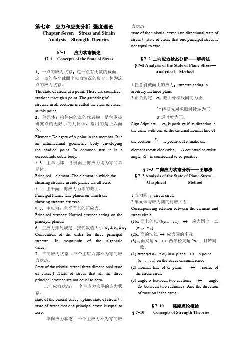
第七章应力和应变分析强度理论Chapter Seven Stress and Strain Analysis Strength Theories§7–1 应力状态概述§7–1 Concepts of the State of Stress1.一点的应力状态:过一点有无数的截面,这一点的各个截面上应力情况的集合,称为这点的应力状态。
The state of stress at a point: There are countless sections through a point. The gathering of stresses in all sections is called the state of stress at this point.2.单元体:构件内的点的代表物,是包围被研究点的无限小的几何体,常用的是正六面体。
Element: Delegate of a point in the member. It is an infinitesimal geometric body enveloping the studied point. In common use it is a correctitude cubic body.* 3.主单元体:各侧面上剪应力均为零的单元体。
Principal element :The element in which the shearing stresses in side planes are all zero.* 4.主平面:剪应力为零的截面。
Principal Planes:The planes on which the shearing stresses are zero.* 5.主应力:主平面上的正应力。
Principal stresses: Normal stresses acting on the principle planes.6.主应力排列规定;按代数值大小Convention of the order for three principal stresses: In magnitude of the algebraic value.7.三向应力状态:三个主应力都不为零的应力状态。

Part II:Mechanics of Materials Combined loadingsCOMBINED LOADINGSObjects of the section:•To analyze the stresses in thin-walled pressure vessels•To develop methods to analyze the stress in members subject to combined loadings(e.g. tension or compression, shear, torsion, bending moments).“Thin wall ”: A vessel having an inner-radius-to-wall-thickness ratio of 10 or more (r/t>= 10).The results of a thin-wall analysis will predict a stress that is approximately 4%less than the actual maximum stressIt is assumed that the stress distribution throughout the vessel’s thickness is uniform or constant.Cylindrical Vessels•A pressure p is developed within the vesselby a contained gas or fluid;•An element shown in the figure is assumedto be subjected to normal stress σ1in thecircumferential or hoop direction and σ2inthe longitudinal or axial direction.•Both stress exert tension on the materialPlane stressFor the hoop stress, the vessel is being sectioned by planes a, b and c.The uniform hoop stress σ1, acting throughout the vessel’s wall, the pressure acting the vertical face of the sectioned gas or fluid.10; 2[( )](2 )0x F t dy p r dy σ=-=∑1pr tσ=It can be imagined as the solidvertical face with p acting.For the axial stress, the vessel is being sectioned by the plane b .The uniform axial stress σ2, acting throughout the vessel’s wall, the pressure p acting the section of gas or fluid. It is assumed that the mean radius r is approximately equal to the vessel’s inner radius.220; (2)()0y Frt p r σππ=-=∑2pr σ=It can be imagined asthe solid section facewith p acting.1pr t σ=22pr tσ=σ1, σ2= the normal stress in the hoop and longitudinal directions, respectively. Each is assumed to be constant throughout the wall of the cylinder, and each subjects the material to tension .p = the internal pressure developed by the contained gas or fluidr = the inner radius of the cylindert = the thickness of the wall (r/t >=10)Spherical Vessels•A pressure p is developed within the vesselby a contained gas or fluid;•An element shown in the figure is assumedto be subjected to normal stress σ2, whichexerts tension on the material.the vessel is sectioned in half using section plane a. Equilibrium in y direction requires:220; (2)()0y F rt p r σππ=-=∑22pr t σ=It can be imagined asthe solid section facewith p acting.THIN-WALLED PRESSURE VESSELS☐Either a cylindrical or a spherical vessel is subjected to biaxial stress.☐The material of the vessel is also subjected to a radial stress σ3, which acts along a radial line. The maximum of it equals to p at the interior wall and decreases to zero at the exterior wall.☐The radial stress σ3will be ignored because σ1and σ2are 5 to 10 times higher than σ3.☐External pressure might cause the vessel to buckle.A member is subjected either an internal axial force, a shear force, a bending moment, or a torsional moment.Several these types of loadings are applied to the member simultaneouslyPrinciple of SuperpositionResultant stress distribution caused by the loads.•A linear relationship exists between the stress and the loads •The geometry of the member should not undergo significant changeAssumptions STATE OF STRESS CAUSED BY COMBINED LOADINGSThe Procedure of Analysisto determine the resultant stress distribution caused by combined loadingsInternal Loadings•Section the member perpendicular to its axis at the point where the stress to be determined and obtain N,M,V and T.•The force components should act through the centroid of the cross section and the moment components should be computed about the centroidal axes .Average Stress Components•Compute the stress component associated with each internal loading.(Distribution of stress acting over the entire cross-sectional area or the stress at a specific point)How?(The neutral axis)NORMAL FORCE P SHEAR FORCE V BENDING MOMENT TORSIONAL MOMENT or THIN-WALLED PRESSURE VESSELS: and SuperpositionOnce the normal and shear stress components for each loadings have beencalculated, use the principle of superposition and determine the resultant normal and shear stress components.x P Aσ=VQ Itτ=y z x z yM z M y I I σ=-+T Jρτ=2m T A t τ=1pr tσ=22pr t σ=Important points (review)☐Pressure vessels: For a thin wall cylindrical pressure vessel with r/t >= 10; the hoop stress is σ1= pr/t. The longitudinal stress is σ2= pr/2t.☐For a thin wall spherical vessels having the same normal tensile stress, which is σ= σ2 = pr/2t.1☐Superposition of stress components: The procedure to analyze the stress state ofa point for a member, which is subjected to a combined loading.Homework assignments: 8-5, 8-15, 8-21, 8-41, 8-54Example 1A force of 15000 N is applied to the edge of the member shown below. Neglect the weight of the member and determine the state of stress at pointsB and C.Solution:1. Internal Loadings. It is sectioned through B and C. For equilibrium at the section, the internal loadings is shown below.2. Stress Components.Normal Force: 150003.75MPa (100)(40)P A σ===Bending moment: The normal force distribution due to bending moment is shown below. 33(40)(100)1212bh I ==N A315000(50)11.25MPa (112)(40)(100)B B My I σ-=-=-=315000(50)11.25MPa (112)(40)(100)c c My I σ=-=-=-yz3. Superposition 3()15000(50)( 3.75)7.5 MPa (112)(40)(100)B B My P I A σ--=-+=-+-=(tension)3()15000(50)( 3.75)15 MPa (112)(40)(100)c c My P I A σ-=-+=-+-=-(compression)Example 2The member shown has a rectangular cross section. Determine the state of stress that the loading produces at point C.Solution:AB F Ax = 16.45 kN; F Ay = 21.93 kN; F B = 97.59 kN1. Internal Loadings. The support reactions on the member have been determined and shown. (Using the equations of equilibrium for the whole member)After the support reactions have known,the internalloadings at section C have been determined and shownin the right figure.2. Stress Components.Normal Force: Shear Force: C C C C It y A V It VQ ''==τSince A= 0, thus Q C = 0, τC = 0 MPa 32.1)250.0)(050.0(45.16===A N C σBending moment: Point C is located aty = c = 125 mm from the neutral axis,so the normal stress at C.MPa 15.63)250.0)(050.0(121)125.0)(89.32(3=⎥⎦⎤⎢⎣⎡==I Mc C σσC =63.15 MPa3. SuperpositionMPa 5.6415.6332.1=+=C σAns.。