工程力学英文版课件10 Shear Stresses and Strains,Torsion
- 格式:ppt
- 大小:1.03 MB
- 文档页数:60
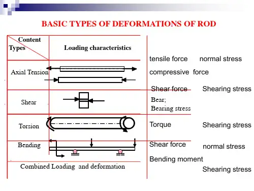
Simple Stress and StrainIn any engineering structure the individual components or members will be subjected to external forces arising from the service conditions or environment in which the component works. If the component or member is in equilibrium, the resultant of the external forces will be zero but, nevertheless, they together place a load on the member which tends to deform that member and which must be reacted by internal forces set up within the material.There are a number of different ways in which load can be applied to a member. Loads may be classified with respect to time:(a) A static load is a gradually applied load for whichequilibrium is reached in a relatively short time.(b) A sustained load that is constant over a long period of time,such as the weight of a structure (called dead load). Thistype of load is treated in the same manner as a static load;however, for some materials and conditions of temperatureand stress, the resistance to failure may be different undershort time loading and under sustained loading.(c)An impact load is a rapidly applied load (an energy load).Vibration normally results from an impact load, andequilibrium is not established until the vibration iseliminated, usually by natural damping forces.(d)An repeated load is a dead that is applied and removedmany thousands of times.(e) A fatigue of alternating load is a load whose magnitude andsign are changed with time.It has been noted above that external force applied to a body in equilibrium is reacted by internal forces set up within the material. If, therefore, a bar is subjected to a uniform tension or compression, i.e.a force, which is uniformly applied across the cross-section, then the internal forces set up are also distributed uniformly and the bar is said to be subjected to a uniform normal tress, the stress being defined asStress=load/area=P/AStress may thus be compressive or tensile depending on the nature of the load and will be measured in units of newtons per square meter (N/m2) or multiple of this.If a bar is subjected to an axial load, and hence a stress, the bar will change in length. If the bar has an original length L and changed in length by an amount QL, the stain produced is defined as follow: Train=change in length/original length=QL/LStrain is thus a measure of the deformation of the material and is non-dimensional, i.e. it has no units; it is simply a ratio of two quantities with the same unit.Since, in practice, the extensions of materials under load are very small, it is often convenient to measure the strains in the form of strain *10-6, i.e. microstrain, when the symbol used becomes UE.Tensile stresses and strains are considered positive in sense. Compressive stresses and strains are considered negative in sense. Thus a negative train produces a decrease in length.A material is said to be elastic if it returns to its original, unloaded dimensions when load is removed. A particular form of elasticity which applies to a large range of engineering materials, at least over part of their load range, produces deformations which are proportional to the loads producing them. Since loads are proportional to the stresses they produce and deformations are proportional to the strains, this also implies that, whilst materials are elastic, stress is proportional to strain, Hooke’s law therefore states thatStress trainThis law is obeyed within certain limits by most ferrous alloys and it can even be assumed to apply to with reasonable accuracy.Whilst a material is elastic the deformation produced by any load will be completely recovered when the load is removed; there is no permanent deformation.Within the elastic limits of materials, i.e. within the limits inwhich Hooke’s law applies, it has been shown thatTress/train=constantThis constant is given the symbol E and modulus of elasticityOr Young’s modulus. ThusE=tress/strainYoung’s modulus E is generally assumed to the same in tension or compression and for most engineering materials had a high numerical value. Typically, E=200*109N/m2 for steel, so that it will be observed from Eq. that trains are normally very small.In most common engineering applications strains rarely exceed 0,1%. The actual of Young’s modulus for any material is normally determined by carrying out a standard test on a specimen of the material.。
应力应变英语Stress and Strain in EngineeringStress and strain are fundamental concepts in the field of engineering, as they are crucial in understanding the behavior of materials and structures under various loading conditions. These two interrelated quantities are essential for the design, analysis, and optimization of engineering systems, from small components to large-scale structures.Stress, in the context of engineering, can be defined as the internal force per unit area acting within a material or structure. It is a measure of the intensity of the internal forces that arise due to the application of external loads or constraints. Stress can be classified into different types, such as normal stress, shear stress, and torsional stress, depending on the direction and nature of the forces acting on the material.Normal stress is the stress that acts perpendicular to the surface of a material, and it can be either compressive or tensile. Compressive stress occurs when the material is subjected to forces that tend to push it together, while tensile stress occurs when the material issubjected to forces that tend to pull it apart. Shear stress, on the other hand, is the stress that acts parallel to the surface of a material, causing the material to slide or deform in a particular direction.Strain, on the other hand, is a measure of the deformation of a material or structure due to the application of stress. It is the change in the size or shape of a material relative to its original dimensions. Strain can be classified into different types, such as normal strain and shear strain, just like stress.Normal strain is the change in the length of a material divided by its original length, and it can be either compressive or tensile. Shear strain, on the other hand, is the change in the angle between two originally perpendicular lines in the material, caused by the application of a shear stress.The relationship between stress and strain is governed by the material's mechanical properties, which can be determined through various testing methods. The most fundamental relationship between stress and strain is described by Hooke's law, which states that for small deformations, the stress in a material is proportional to the strain. This linear relationship is valid for many materials, such as steel and aluminum, within their elastic range.However, not all materials exhibit a linear stress-strain relationship.Some materials, such as rubber and certain polymers, exhibit a non-linear relationship, where the stress-strain curve is curved and the material exhibits more complex behavior, such as viscoelasticity or plasticity.Understanding the stress-strain relationship of materials is essential for the design and analysis of engineering structures and components. By knowing the stress and strain values, engineers can determine the safety and reliability of a structure under various loading conditions, as well as optimize the design to ensure that the material is being used efficiently and effectively.For example, in the design of a bridge, engineers need to consider the stresses and strains that will be experienced by the structure due to the weight of the bridge, the traffic load, and environmental factors, such as wind and earthquakes. By analyzing the stress and strain distribution within the bridge, engineers can ensure that the structure is designed to withstand the expected loads without exceeding the material's strength or deformation limits.Similarly, in the design of a mechanical component, such as a gear or a shaft, engineers need to consider the stresses and strains that will be experienced by the component during operation. By analyzing the stress and strain distribution within the component, engineers can optimize the design to minimize the risk of failure and ensurethe component's reliability and longevity.In conclusion, stress and strain are fundamental concepts in engineering that are essential for the design, analysis, and optimization of engineering systems. By understanding the relationship between stress and strain, engineers can ensure the safety, reliability, and efficiency of their designs, ultimately contributing to the advancement of technology and the betterment of society.。
Unit 2 Stress and strain应力和应变1.Introduction to Mechanics of Materials材料力学的介绍Mechanics of materials is a branch of applied mechanics that deals with the behavior of solid bodies subjected to various types of loading. It is a field of study that is known by a variety of names, including “strength of materials”and “mechanics of deformable bodies.”The solid bodies considered in this book include axially-loaded bars, shafts, beams, and columns, as well as structures that are assemblies of these components. Usually the objective of our analysis will be the determination of the stresses, strains, and deformations produced by the loads; if these quantities can be found for all values of load up to the failure load, then we will have obtained a complete picture of the mechanical behavior of the body.材料力学是应用力学的一个分支,涉及受不同类型载荷的固体的性能。
Part II:Mechanics of Materials Transverse shearSHEAR IN STRAIGHT MEMBERS•Shear forces (V)and bending moments (M)are developed generally in beams.Internal force and moment•The shear V is the result of a transverse shear-stress distribution over the beam’s cross section.Due to the complementary property ofthe shear, associated longitudinal shearstresses will also act along longitudinalplanes of the beam.Due to the complex shear stress, shear strains will be developed and these will tend to distort the cross section.The cross section of the beam under a shear V will warp,not remain plane.All cross sections of the beam remain plane and perpendicular to the longitudinal axis. –the assumption for the flexure formulaAlthough the assumption is violated when the beam is subjected to bending moment and shear force, the warping is small enough to be neglected.A slender beam'''''0; ' ()0 () -()()0 ()x A A A A A F dA dA tdx M dM M ydA ydA tdx II dM ydA tdx I σστττ+=--=+-=⎛⎫= ⎪⎝⎭∑⎰⎰⎰⎰⎰⎰=')(1A ydA dx dM It τ'''''0; ' ()0 () -()()0 ()x A A A A A F dA dA tdx M dM M ydA ydA tdx II dM ydA tdx I σστττ+=--=+-=⎛⎫= ⎪⎝⎭∑⎰⎰⎰⎰⎰⎰=')(1A ydA dx dM It τ'''''0; ' ()0 () -()()0 ()x A A A A A F dA dA tdx M dM M ydA ydA tdx II dM ydA tdx I σστττ+=--=+-=⎛⎫= ⎪⎝⎭∑⎰⎰⎰⎰⎰⎰=')(1A ydA dx dM It ττ⎰=')(1A ydA dx dM It τItVQ =τ=the shear stress at the point located a distance y’ from the neutral axis V =the internal result shear forceI =the moment of inertia of the entire cross-sectional area computed about theneutral axist = the width of the member’s cross -sectional area, measured at the point where is to be determined'''A y ydA Q A ==⎰Shear formulaIt applies to determine transverse shear stress in the beam’s cross -sectional area ττ'''A y ydA Q A ==⎰Area =A '9Rectangular Cross Section b y h b y h y h y A y Q )4(21 )2()2(2122-=-⎥⎦⎤⎢⎣⎡-+=''=b bh b y h V It VQ )121(])4/)[(21(322-==τ)4(6223y h bh V -=τ•The maximum value •The position SHEAR STRESS IN BEAMS , 02h y τ=±=max 0, 1.5V y Aτ==Rectangular Cross SectionV h h h h h h V y y h h V bdy y h bh V dA h h h h A =+-+=-=-=--⎰⎰)]88(31)22(4[6 ]314[6 )4(6 33232/2/3232/2/223τmax 0, 1.5V y Aτ==Circular cross section2342233max r r r Q yA ππ⎛⎫⎛⎫=== ⎪ ⎪⎝⎭⎝⎭44r I π=2b r =Hollow circular cross section()332123max Q yA r r ==-()44214I r r π=-212()b r r =-•The shear stress varies parabolically•The shear stress will vary only slightlythroughout the web•A jump occurs at the flange-web junction. Shear stress?Direction?WhyWeb-Flange BeamLimitations on the Use of the shear FormulaAssumption of the shear formula: the shear stress is uniformly distributed overthe width b at the section.max τ'is only about 3% greater than , which represents the average maximum shear stress.ItVQ =max τ•The shear stress at the flange-webjunction is not accurate due to stressconcentration.•The inner regions of the flanges arefree boundaries, however the shearstress determined by the shear formulais not equal to zeroThese limitations are not important since most engineers need to calculate the average maximum shear stress, which occurs at the neutral axis, where b/h ratio is very small.to determine the shear stress distribution with the shear formula.•Section the member perpendicular to its axis at the point where the shear stress to be determined.Internal Shear Force, V(x)Section Property•Determine the location of the neutral axis , the moment of inertia I about the neutral axis;•Imagine a horizontal section through the point where the shear stress is to be determined. Measure the width t of the area at this section.•where is the distance to the centroid of measured from the neutral axis. A y A d y Q A ''='=⎰'y 'The Procedure of AnalysisA '16Shear Stress •It VQ =τThe beam shown in the figure is made of wood and is subjected to a resultant internal vertical shear force V = 3 kN.(a) Determine the shear stress in the beam at point P and(b) compute the maximum shear stress in the beam.Example 1Part (a).Section property. The moment of inertia of the cross-sectional area computed about the neutral axis is 463mm 1028.16)125)(100(121121⨯===bh I 34mm 1075.18 )100)(50)](50(215.12[⨯=+=''=A y Q Shear stressMPa 346.0kN/mm 1046.3 )100)(1028.16()1075.18)(3(2464=⨯=⨯⨯==-It VQ P τAns.A horizontal section line is draw through point P andthe partial area A’ is shown SolutionPart (b).Section property. The maximum shear stress occurs at the neutral axis, since t is constant throughout the cross section and Q is largest for this case. For the dark shaded area A’, we have34mm 1053.19)5.62)(100(25.62⨯=⎥⎦⎤⎢⎣⎡=''=A y Q Shear stress. Applying the shear formula yields:MPa360.0kN/mm 1060.3 )100)(1028.16()1053.19)(3(2464max =⨯=⨯⨯==-It VQ τNote that this is equivalent to MPa 36.0kN/mm 106.3)125)(100(35.15.124max =⨯===-A V τ☹The members having short or flat cross sections (The shear stress is not uniform across the width)☹At points where the cross section suddenly changes ☹The edge of the cross section does not parallel to the y axis. yVSHEAR STRESS IN BEAMS。
Department of Chemical EngineeringStrength of Materials for Chemical Engineers (0935381)Chapter 1Simple Stress and StrainThe main objective of the study of the mechanics of materials is to provide the engineer with the means of analyzing and designing various machines and load bearing structures.StressStress is the internal resistance offered by a unit area of the material from which a member is made to an externally applied load.Direct or normal stress σis calculated using the following equation:AP ==Force the resisting Area sectional Cross Original Load Applied σAnd has a unit of Pa or N/m 2.StrainStrain is the total deformation divided by the original length of the bar.Normal or longitudinal strain is calculated using the following equation:%100Strain Percentage Length Original Length in Change ×∆=∆==LL L L εTensile stresses and strain are considered positive increase in length. Compressive stresses and strain are considered negative producing a decrease in length.Materials may be classified into(1) Elastic material which undergoes a deformation when subjected to an external loading such that, the deformation disappears on the removed of the loading, (Rubber).(2) A plastic material undergoes a continuous deformation during the period of loading and the deformation is permanent and the material does not regain its original dimensions on the removal of the loading, (Aluminum).(3) A rigid material does not undergo any deformation when subjected to an external loading, (Glass and Cast iron).Loads1- Dead loads: static in nature such as the self weight of the roof.2- Live loads: fluctuating in nature, does not remain constant such as a weight of a vehicle moving on a bridge.3- Tensile loads.4- Compressive loads.5- Shearing loads.Load Stress StrainTensile Tensile TensileCompressive Compressive CompressiveShearing Shear ShearThe actual values of modulus of elasticity E and maximum stress σultimate are determined by carrying out a standard tensile best on a specimen of the material.The bar is subjected to a gradually increasing tensile load until failure occurs. Measurements of the change in length of a selected gauge length of the bar are recorded throughout the loading operation by means of extensometers. And a graph of load against extension or stress against strain is produced as shown.1. Form OA Hooke’s low is obeyed, i.e. the material behaves elastically and stress is proportional to strain, giving the straight line graph indicated.For elastic materials, stress is proportional to strain:L A FL LL A F E ∆=∆===εσStrain StressThe unit of E is N/m2 (GN/m2).2.After A the linear nature of the graph disappears and this point is termed the limit ofproportionality.3.B elastic limit, i.e. the deformation are completely recovered when the load is removed(i.e. strain returns to zero), but Hook’s law does not apply.4.Yield point is the stress at which a noticeable elongation of the sample occurs with noapparent increase in lead.5.After B plastic deformation occurs and strains are not totally recoverable, and relativelyrapid increases in stain occur without correspondingly high increases in load or stress.6.C is termed the upper yield point and D is the lower yield point.The deformation at the yield point is only local in nature. It starts at one point and that region gets work-hardened, so the flow starts again at a region adjacent to the former region. Hardening occurs here too, and the process continues. Thus, the flow is spread throughout the specimen.Each successive work hardening tends to increase the stress. But the effect is only momentary, and again the stress value falls, due to the flow in the neighboring region.As a result, the entire specimen gets work- hardened and the stress begins to rise, deformation becomes uniform.7.Beyond the yield point some increase in load is required to take the strain to point E,between D and E the material is said to be in the elastic-plastic state.8.Beyond E the cross-sectional area of the bar begins to reduce rapidly over a relativelysmall length of the bar and the bar is said to neck. This necking takes place whilst the load reduces, and fracture of the bar finally occurs at point F.9. Stress at failure, termed the maximum or ultimate tensile stress is given by the load at Edivided by the original cross-sectional area of the bar. ( Tensile Strength) ToughnessThe area under the entire stress-strain curve from zero to rupture gives the property known as the modulus of toughness [The energy per unit volume necessary to rupture the material]. Modulus of ResilienceThe area the stress-strain curve and if evaluated from zero to the elastic limit it is defined as the maximum strain energy per unit volume that a material will absorb without permanent deformation.Proof StressFor certain materials, for example, high carbon steel it is not possible to detect any difference between the upper and lower yield point and in some case no yield point exist at all.In such cases a proof stress is used to indicate the onset of plastic strain. The 0.1% proof stress for example is that stress which when remove produce a permanent strain of 0.1% of the original gauge length.1.Mark the point P on the strain axis which is equivalent to 0.1% strain.2.From P draw a line parallel with the initial straight line portion of the tensile test curveto cut the curve in N. The stress corresponding to N is then the 0.1% proof stress.3. A material is considered to satisfy its specification if the permanent set is no more than0.1% after the proof stress has been applied for 15 second and removed.Ductile MaterialsThe capacity of a material to allow large extensions, i.e. the ability to be drawn out plastically is termed its ductility.A quantitative value of the ductility is obtained by measurement of the percentage elongation or percentage reduction in areaarea Original portion necked of area sectional -cross in Reduction area in Reduction length gauge Original fracturelength to gauge in increase n Eleongatio Percentage ==MalleabilityMaterials ability to be hammered out into thin sheets such as lead is called malleability. Brittle MaterialsThey exhibit relatively small extensions to fracture such as glass and cast iron. There is little or no necking at fracture for brittle materials.Shear StressMaterial is subjected to a set of equal opposite forces. There is a tendency for one layer of the material to slide over another to produce the form of failure, if this failure is restricted then shear stress (τ) is set up.AP ==shear resisting Area load Shear τThe shear stress is tangential to the area and has units similar to normal stress, Pa or N/m 2. Shear strain (γ) is measured in radians (non dimensional) has no units.Within the elastic range shear strain is proportional to shear stress.γτ==strain Shear stress Shear (G)rigidity of ModulusSingle ShearA P =τ Double ShearA P 2=τ Factor of SafetyStress working Allowable Stress)Proof (or Stress Yield Safety of Factor tomodified Stress working Allowable Stress Maximum Safety of Factor ==Typical values range from 2.5 (for relatively low consequence, static load) to 10 (for shock load and high Safety risk applications).LoadWorking Allowable failure at Load factor Load = Temperature StressesWhen the temperature of a component is increased or decreased the material respectively expands or contracts.If this expansion or contraction is not resisted in any way then the process takes place free of stress.If however, the changes in dimensions are restricted then stresses termed temperature stresses will be set up.increase e temperatur :lengthoriginal :expansion of t coefficien linear :T L TL L ∆∆=∆αα New length:)1(T L T L L L L L L ∆+=∆+=′∆+=′ααIf this expansion is prevented then compressive strain will be produced:()T L L L L L ∆+∆=∆=ααε1Since is very small compared with unity thenT LL L L L ∆=∆=∆=ααεThe thermal stress will be:T E E ∆==αεσo If temperature rises then compressive stress will be produced.o If temperature falls then tensile stress will be produced.CreepIs the gradual increase of plastic strain in a material with time at constant load, (quasi–viscous flow of the metal).FatigueIs the failure of a material under fluctuating stresses each of which is believed to produce minute a mounts of plastic strain. Or fatigue is the property by which they fail at a relatively low value of stress when the stress is repeated or reversed.。