热能与动力工程毕业设计文献翻译
- 格式:doc
- 大小:431.50 KB
- 文档页数:12
2.5Natural Convection 自然对流Heat transfer involving motion in a fluid caused by the difference in density and the action ofgravity is called natural or free convection. Heat transfer coefficients for natural convection are generally much lower than for forced convection, and it is therefore important not to ignore radiationin calculating the total heat loss or gain. Radiant transfer may be of the same order of magnitude as natural convection, even at room temperatures, since wall temperatures in a room can affect human comfort. 由于密度差和重力作用引起流体运动而产生的热传递称为自然对流或自由对流。
自然对流的传热系数一般远低于强迫对流,因此在计算总的吸热量或放热量时,主要的一点就是不要忽略辐射热。
辐射热传递与自然对流可以有相同的数量级,甚至在室温下也如此,因为室内墙体温度影响人体的舒适感。
Natural convection is important in a variety of heating and refrigeration equipment: (1) gravitycoils used in high humidity cold storage rooms and in roof-mounted refrigerant condensers, (2) the evaporator and condenser of household refrigerators, (3) baseboard radiators and convectors for space heating and (4) cooling panels for air conditioning. Natural convection is also involved in heat loss or gain to equipment casings and interconnecting ducts and pipes. 在各种供热和制冷设备中自然对流是非常重要的:(1)在高湿度冷藏室内及室内安装的制冷剂冷凝器内使用的重力盘管;(2)家用冰箱的蒸发器和冷凝器;(3)空间采暖用的踢脚板散热器和对流器;(4)空调用辐射对流护壁板。

Combustion and NO x emission characteristics of a retrofitted down-fired 660MW e utility boiler at different loadsZhengqi Li ⇑,Guangkui Liu,Qunyi Zhu,Zhichao Chen,Feng RenSchool of Energy Science and Engineering,Harbin Institute of Technology,92,West Dazhi Street,Harbin 150001,Chinaa r t i c l e i n f o Article history:Received 7September 2010Received in revised form 23November 2010Accepted 20January 2011Available online 12February 2011Keywords:Down-fired boiler RetrofitCarbon content in fly ash Thermal efficiencya b s t r a c tIndustrial experiments were performed for a retrofitted 660MW e full-scale down-fired boiler.Measure-ments of ignition of the primary air/fuel mixture flow,the gas temperature distribution of the furnace and the gas components in the furnace were conducted at loads of 660,550and 330MW e .With decreasing load,the gas temperature decreases and the ignition position of the primary coal/air flow becomes farther along the axis of the fuel-rich pipe in the burner region under the arches.The furnace temperature also decreases with decreasing load,as does the difference between the temperatures in the burning region and the lower position of the burnout region.With decreasing load,the exhaust gas temperature decreases from 129.8°C to 114.3°C,while NO x emissions decrease from 2448to 1610mg/m 3.All three loads result in low carbon content in fly ash and great boiler thermal efficiency higher than 92%.Com-pared with the case of 660MW e before retrofit,the exhaust gas temperature decreased from 136to 129.8°C,the carbon content in the fly ash decreased from 9.55%to 2.43%and the boiler efficiency increased from 84.54%to 93.66%.Ó2011Elsevier Ltd.All rights reserved.1.IntroductionReserves of anthracite and lean coal are abundant and globally distributed.The use of anthracite and lean coal,which have low-volatility contents,presents difficulties in ignition and burnout.More and more research has been conducted around the world to solve these problems.At present,down-fired combustion is widely applied in the power industry to consume low-volatility coals,and its main merit is that it achieves a high degree of burn-out by prolonging the residence time of pulverized-coal in the fur-nace.However,a practical down-fired boiler operation still suffers from the problems of high carbon content in the fly ash and poor flame stabilization at low load without oil support firing.Precise understanding of the behavior of char particles in pul-verized-coal combustion systems is critical in determining funda-mental processes that occur during heterogeneous bustion data obtained for full-scale equipment can give the combustion and NO x emission characteristics of real combustors,in particular the turbulent flow of industrial coal flames.As a re-sult,studies using full-scale equipment are highly desirable and a necessity.In the surrounds of wall-fired boilers,measurements are made of the local mean concentrations of O 2,CO,CO 2,and NO x ,gas temperatures,and char burnout through several observ-ing doors in the utility boilers [1–5].Experiments have also been performed for tangentially fired boilers [6–9].However,for down-fired boilers adopting Foster Wheeler technology,there has only been the work of Li et al.,who measured the gas temperature,gas species concentrations in the furnace and carbon content in the fly ash in a 300MW e boiler before and after retrofit [10–14].In the present study,in situ experiments were carried out for a 660MW e down-fired pulverized-coal boiler after retrofit;this unit has the maximum capacity of any currently used worldwide [15].Measurements of ignition of the primary air/fuel mixture flow,the gas temperature distribution of the furnace and the gas compo-nents in the furnace were made for this full-scale boiler at the rated,middle and half loads.The collected data were used to deter-mine the combustion and NO x emissions characteristics of the boi-ler at different loads.The results obtained from these experiments help solve similar problems and benefit the design and operation of 600MW e and 1000MW e down-fired boilers,and the data can be used to support theoretical and numerical calculations.2.The utility boilerThe investigated 660MW e boiler,having the largest capacity of any down-fired boiler in the world,was made by Foster Wheeler (FW)Corp.Fig.1a is a schematic diagram of the furnace.Arches di-vide the furnace into two:the lower furnace below the arches and the upper furnace above the arches.Originally,36cyclone burners were arranged on the arches to produce a W-shaped flame.The fuel-rich flow streaming from the cyclone nozzle is near the0306-2619/$-see front matter Ó2011Elsevier Ltd.All rights reserved.doi:10.1016/j.apenergy.2011.01.048Corresponding author.Tel.:+8645186418854;fax:+8645186412528.E-mail address:green@ (Z.Li).water-cooled wall while the fuel-leanflow jetting from the fuel-lean pipe faces the furnace center.Under the arches,there are three tiers of secondary air denoted D,E and F,all of which are fed into the furnace horizontally.Details of the specific structure of this kind of boiler can be found in the literature[10–13].During practical operation,the boiler suffers from great resis-tance and serious abrasion of the cyclone and high carbon content infly ash up to7–10%.Fuel-richflows form after the separation of the coal/airflows in the cyclones.The swirl intensities of fuel-rich flows decrease at the exits under the effect of the adjustable vane, which provides great resistance.The fuel-richflows with residual swirl have little rigidity and abrade the nozzles of the cyclones [16].The secondary air under the arches enters the furnace horizon-tally and mixes prematurely with the fuel-richflow.This reduces the down-forwardflow and space for combustion and decreases the temperature in the lower furnace,which causes a series of problems including the delayed ignition of pulverized-coal and high carbon content in thefly ash[13,17].There is fuel-leanflow with low momentum and shallow penetration depth near the furnace center, which readily shortens theflame and reduces upflow to the burnout region quickly.This is also a reason for the poor burnout degree of coal particles and high carbon content in thefly ash[18].In2009,Li et al.retrofitted the combustion system with many items.Fig.1b is a schematic diagram of the retrofitted combustion system.A fuel louver concentrator replaced the original cyclone as it has much lower resistance than the cyclone.The fuel/airflowfirst passes through the louver concentrator and separates into fuel-rich flow and fuel-leanflow.The fuel-richflow further divides into two and is injected into the furnace through the original primary air ducts facing the furnace center while the fuel-leanflow as vent air is injected into the furnace near the wall.The vent air ducts are con-trolled by valves.The horizontal secondary air is modified by the F-tier secondary air with an angle of declination of20°.In this retrofitted boiler,measurements were conducted at loads of660,550and330MW e with a constant opening of the vent air valves.3.Data acquisition methods and experimental conditionsThe formal in situ experiments were carried out in the2026tph down-fired pulverized-coal boiler to investigate certain aspects of the combustion process and NO x formation in the furnace.During the experiments,soot blowing and sewer bleeding were not per-mitted.The coal used in the experiments was a mixture of anthra-cite and lean coal.Sample characteristics of coals before and after retrofit are presented in Table1.The following parameters were measured:(1)The gas temper-ature of the furnace was measured with a leucoscope through observing doors in the front,rear and side walls.The layout of the observing doors is shown in Fig.2.The measurement error is 50°C.(2)The gas temperature of the furnace was measured with a nickel chromium–nickel silicon thermocouple through observing doors1,2and3.As shown in Fig.2,observing door1is in the air-flow zone of the tier D and E slots,observing door2is in the airflow zone of the tier F slots,and observing door3is above the arches. The end of the bare thermocouple was exposed in the furnace,so the temperature measured should be higher than the local gas temperature because of highflame radiation.However,because of radiation between the bare thermocouple and the water-cooled wall,and the close proximity of the two,the temperature mea-sured should be lower than the local gas temperature.The calcula-tions have indicated that in the region of highest temperature the ‘‘true’’temperature do not exceed the measured one by more than 8%[3,19].The thermocouples used were thoroughly checked be-fore leaving the factory,giving high confidence in the temperature measurement results.To minimize errors due to ash deposition,Table1Characteristics of the coal used in the experiments before and after retrofit.Quantity Before retrofit After retrofitProximate analysis,wt.%(as received)Volatile10.729.29Ash30.8431.51Moisture0.54 2.48Fixed carbon57.9056.72Net heating value(kJ/kg)23,53121,250Ultimate analysis,wt.%(as received)Carbon59.7059.48Hydrogen 2.95 2.52Oxygen 3.81 3.53Nitrogen0.820.83Sulfur 1.340.79Z.Li et al./Applied Energy88(2011)2400–24062401the thermocouples were frequently retracted from the furnace and, where necessary,any deposits were carefully removed.Moreover, the probes were replaced if there was any thermal distortion ob-served.(3)The primary air/flow temperature distribution was measured with the same thermocouple inserted parallel to the axis of the fuel-rich pipe,as shown in Fig.1.(4)Gas compositions were sampled using a water-cooled stainless steel probe2.5m in length for analysis of the local mean O2,CO and NO x concentrations.As shown in Fig.3,the probe comprised a centrally located10mm (inner diameter)tube,through which quenched samples were evacuated,surrounded by a tube for probe cooling.The probe was cleaned frequently by blowing high-pressure air through it to maintain a constant suction rate.The water-cooled probe was inserted into the furnace through observing doors1–3(see Fig.2).The gases withdrawn were analyzed online using a Testo 350M system.Theflue gas after the air heater was also analyzed online.Calibrations with standard mixtures including zero concen-trations were performed before each measurement session.The measurement error for O2and CO2concentrations was1%,while that for CO and NO x concentrations was50ppm.(5)Unburnt car-bon infly ash was determined by collectingfly ash using a particle-sampling device with constant suction speed.Values of the main operating parameters for the three operating loads are listed in Table2.4.Results and discussionFig.4shows the gas temperature distribution of the fuel-burn-ing zone along the cyclone axes of the burners;zero points were set at the tips of the burner nozzles in the furnace.With decreasing load,the gas temperature decreases and the ignition position of the primary coal/airflow becomes farther along the axis of the fuel-rich pipe in the burner region under the arches,especially as the load decreases from550to330MW e.For the rated load,the gas temperature rises rapidly as the measurement point extends to lower positions,exceeding1000°C at a position400mm from the end of the fuel-rich nozzle and exceeding1200°C at 1400mm.For the load of550MW e,the gas temperature is a little lower than that for the rated load in the burner region,exceeding 1000°C at a position800mm from the fuel-rich nozzle.For the half load,the gas temperature rises slowly and the temperature gradi-ent is lower than in the other two cases,barely reaching1000°C at 2400mm.The mass ratio of coal/air decreases as the load decreases,indi-cating that the concentration of pulverized-coal falls in the primary air and the momentum of coal/airflow decreases,resulting in aTable2Boiler operating conditions and measurement results.Quantity Before retrofit After retrofit660MW e660MW e550MW e330MW eTotalflux of the primary air(kg/s)121127110.574Temperature of the primaryair(°C)130124125114Totalflux of the secondaryair(kg/s)657620511396Temperature of thesecondary air(°C)398405397362 Coal feeding rate(ton/h)268.6282.7244.6147.7 O2at the furnace exit(dryvolume%)3.35 2.58 2.02 5.31O2influe gases(dry volume%)4.76 3.99 3.047.27NO x influe gas(mg/m3at6%O2dry)1181244821631610Carbon infly ash(%)9.55 2.43 6.02 3.24 Exhaust gas temperature(°C)136129.8119.3114.3Thermal efficiency of the boiler(%)84.5493.6692.5992.862402Z.Li et al./Applied Energy88(2011)2400–2406shallower penetration depth and shorter residence time of the pri-mary coal/airflow in the lower furnace.For these reasons,the gas temperature measured along the axis direction of the fuel-rich pipe decreases and the ignition of the primary coal/airflow in the bur-ner region under the arches is farther along the axis.The mass ratio of coal/air is defined to indicate the coal concen-tration in the primary air.As the load falls from660to330MW e, the mass ratio of coal/air drops from0.618to0.554,which indi-cates an obvious decrease in the coal concentration;thus,the heat and time needed for coal ignition increase.This is one of the rea-sons for the low gas temperature in the burner region and far igni-tion position of the coal particles at half load.For the load of 550MW e,the mass ratio of coal/air is0.615,which is little different to that for the rated load.Furthermore,the quantity of primary air and coal feed rate both decrease as the load decreases,as does the momentum of coal/airflow,leading to shallow penetration of the pulverized-coal in the lower furnace.The short residence times then lower the overall temperature of the burner zone to the ex-tent that the fuel-richflow cannot obtain sufficient heat from the recirculating up-flowing gases(see Fig.1).Fig.5presents furnace gas temperature variations as measured using the thermocouple inserted through observing doors1–3.On the whole,the gas temperature measured through observing doors 1–3decreases with decreasing load.In the case of the temperature distribution measured through observing door1,the gas tempera-turefirst increases and then decreases because some of the high-temperature gas recirculates into the near-wall zone.As the measurement points move deeper into the furnace,the measured temperature begins to fall as the thermocouple enters the fuel-rich flow.At the rated load,the gas temperature is steadily around 1000°C at points further than1400mm,while for the load of 550MW e,the measured temperature is a little lower.At the same position but for a load of330MW e,the temperature falls below 700°C gradually,indicating that the fuel-richflow has not ignited. This temperature sequence is the same as that for the temperature gradients of the fuel-richflow mentioned above,indicating that ignition conditions worsen as the load decreases.In the cases of measuring the temperature through observing doors2and3,once the temperature reached1250°C,no further measurements were taken at deeper positions for the simple rea-son of protecting the thermocouple from burnout.From the rela-tively limited temperature distribution,Fig.5shows that in the zone near observing door2,the temperature rises rapidly at loads of660and550MW e,and at400mm,temperatures already exceed 1250°C.This indicates that coal burns more intensely in the lower furnace in both cases.At the load of330MW e,the temperature rises to nearly1200°C at the position1800mm from the side wall, increasing more slowly than in the other two cases.As illustrated above for the gas temperature in the burner region,the momentum of coal/airflow at half load is low,which results in a shallow pen-etration depth and short residence time of the primary coal/air flow and low furnace temperature in the lower furnace.Further-more,the F-tier air accounts for a large proportion of the secondary air entering the furnace under the arches;therefore,much of the air does not take part in combustion immediately,which decreases the temperature in the region near observing door2.In the zones near observing door3above the arches,the temperature increases to more than1100°C at a load of330MW e,which is just a little lower than the temperature near observing door2.This can be ex-plained by the delay in the fuel-richflow ignition causing much of the fuel to burn in the upper furnace.Fig.6presents furnace temperature variations measured through observing doors for the three loads.The furnace tempera-tures shown in Fig.6are averages of values measured through observing doors at the same level.In the three cases,gas tempera-ture peaks are all in the lower furnace,and the distances from the peak positions to the exit of the furnace are relatively large.Resi-dence times for coal burning in the higher-temperature zone are thus longer,which favors fuel burnout.The difference between temperatures in the burning region and the lower position of the burnout region decreases as the load decreases,and is just35°C at a load of330MW e.This is because the momentum of coal/air flow decreases,which results in a shallower penetration depth and shorter residence time of the primary coal/airflow in the lower furnace;the ignition position becomes farther from the fuel-rich nozzle,and more pulverized-coal combusts completely in the upper furnace.Moreover,the temperature in the furnace decreases with the decreasing load.The reason for this is that the total heatZ.Li et al./Applied Energy88(2011)2400–24062403provided to the furnace also falls with decreasing load,decreasing the furnace temperature.Fig.7shows the variations in gas species concentrations in the zones near observing doors1–3.Gas species concentration mea-surements begin400mm from the side wall to avoid the effect of an air leak.In all three cases,the O2concentration sequence is C(door1)>C(door2)>C(door3),which describes well theflow of coal as illustrated in Fig.1b.Fuel-richflowsfirst inject down-ward into the furnace and then reverse their direction upwards in the down-fired boiler.The coal/airflows pass sequentially through the observation doors1,2,and3and O2is consumed con-tinuously along the path of theflame.Thus,in each case,the O2 concentration in the zone near observation door1was the highest, that in the zone near observation door2was intermediate and that near observation door3was the lowest.In the airflowflow zone of the D and E tiers and in the zone near the wall,a great quantity of hot gas lowers the measured O2con-centration.When the measurement points are deeper and closer to the fuel-richflow,the measured value increases.O2concentra-tions near observing door1increase with decreasing load,espe-cially from550to330MW e.For loads of660and550MW e,at the position1800mm from the wall,O2concentrations are nearly 14%,suggesting that the fuel-richflow is beginning to react and a certain amount of O2is being consumed.For the load of 330MW e,however,O2concentrations are higher than18%,indi-cating that the fuel-richflow has not ignited,which agrees with the conclusion drawn from the temperature analysis.In the near-wall zone of observing doors2and3,O2concentrations at half load are higher than in the other two cases,even as high as8%in the near-wall zone of observing door3.At all three loads,CO concentrations strictly rule contrary to O2 concentrations.In the zones near observing doors1–3,the higher the O2concentration,the lower the CO concentration.In the air-flowflow zone of the D and E tiers,CO concentrations decrease with decreasing load because of the delayed ignition of the fuel/ airflow.In the near-wall zone of observing doors2and3,CO con-centrations in the case of the half load are lower than in the other two cases because of the highly oxidizing atmosphere in the furnace.2404Z.Li et al./Applied Energy88(2011)2400–2406In the zone near port1at loads of660and550MW e,volatiles are released and form a certain amount of NO x.However,biased combustion restricts the formation of NO x,and hence,NO x concen-tration here is only645mg/m3and630mg/m3respectively at a position1800mm from the wall.However,for the load of 330MW e,the NO x concentration is as high as3706mg/m3at the same position,because the high O2concentrations form the strong oxidative atmosphere near the observing door1.Moreover,the fuel/airflows with weak rigidity mix with the fuel gas quickly in the furnace;these are the reason for the high NO x concentration. Compared with those measured through observing door1,NO x concentrations for660and550MW e operation increase rapidly in the airflow zone of observing door2because fuel–NO forms con-stantly with further combustion of the pulverized-coal and ther-mal NO increasingly forms under the high-temperature condition in the lower furnace.The NO x concentration at a load of 550MW e is lower than that for the rated load because of the re-duced fuel–NO formation with a lower coal feed rate and the low-er-furnace temperature in this zone.In the case of330MW e,NO x concentrations decrease sharply,because the reducing atmosphere become higher with a great amount of O2consuming.In the zone near observing door3,the NO x concentration decreases with decreasing load.Table2lists results obtained for theflue gas after the air hea-ter.It is obvious that as the load decreases,the exhaust gas tem-perature decreases from129.8°C to114.3°C,while NO x emissions decrease from2448to1610mg/m3.Overall,the NO x content in theflue gas at the three loads was at high levels, exceeding the proposed Chinese emission standard for anthracite (1100mg/Nm3).To decrease these emissions,further technolo-gies,such as over-fire air[15,20],selective catalytic reduction and selective non-catalytic reduction[21,22]should be taken into account.All three loads result in low carbon content in thefly ash and great boiler thermal efficiency higher than92%.The O2 concentrations at the furnace exit when operating at660and 550MW e were2.58%and2.02%,respectively,with the small dif-ference between the two caused by thefluctuation of air supply during operation.The carbon in thefly ash at a load of550MW e was6.02%,which is higher than that at660MW e because the lower-furnace temperature was lower by as much as50°C than the temperature at the higher operating load.To enhance heat absorption in the reheater and to ensure sufficient temperature of the reheat steam,the method of increasing the excess air coef-ficient is commonly adopted when operated at330MW e.Thus, the O2concentration at the furnace exit at330MW e was5.31%, much higher than that at660or550MW e.Despite the high O2 concentration,the quantity of air supplied,including both pri-mary and secondary air,was low for the330MW e case,being only63%of the quantity supplied at660MW e and76%of the quantity supplied at660MW e,as shown in Table2.Therefore, the mean velocity of the fuel gas was lower and the residence time of pulverized-coal was longer in the furnace.These factors explain the high degree of burnout of pulverized-coal and low carbon content in thefly ash.Table2also shows the main operating parameters and mea-surement results at a load of660MW e before the combustion sys-tem retrofit.After retrofit,the exhaust gas temperature decreased from136to129.8°C,the carbon content in thefly ash decreased from9.55%to 2.43%and the boiler efficiency increased from 84.54%to93.66%.However,the NO x content in theflue gas (O2=6%)was higher than before the retrofit,because premature ignition of the pulverized-coal prolonged the residence time of coal particles in the lower furnace with high temperature.Furthermore, the O2concentration in theflue gas decreased from4.76%to3.99%, which increased the NO x concentration after conversion of O2at 6%.5.ConclusionIndustrial experiments were performed in a retrofitted 660MW e full-scale down-fired boiler.Measurements of ignition of the primary air/fuel mixtureflow,gas temperature distribution of the furnace and the gas components in the furnace were con-ducted at loads of660,550and330MW e.The results were as follows.With decreasing load,the gas temperature decreases and the ignition position of the primary coal/airflow becomes farther along the axis of the fuel-rich pipe in the burner region under the arches, especially as the load decreases from550to330MW e.With decreasing load,the gas temperature measured through observing doors1–3decreases,the ignition conditions worsen. Moreover,the combustion intensity of pulverized-coal reduces in the lower furnace.The furnace temperature also decreases with decreasing load,as does the difference between temperatures in the burning region and in the lower position of the burnout region.O2concentrations near observing door1increase with decreas-ing load,while O2concentrations at half load are higher than in the other two cases in the near-wall zone of observing doors2and3. CO concentrations strictly rule contrary to O2concentrations.The higher the O2concentration,the lower the CO concentration near observing doors1–3.NO x concentrations(O2=6%)near observing door1were low at loads of660and550MW e than at the load of 330MW pared with those measured through observing door 1,NO x concentrations for660and550MW e operation increase rapidly in the airflow zone of observing door2while NO x concen-trations at the load of330MW e decrease.In the zone near observ-ing door3,the NO x concentration decreases with decreasing load.With decreasing load,the exhaust gas temperature decreases from129.8°C to114.3°C,while NO x emissions decrease from 2448to1610mg/m3.All three loads result in low carbon content in thefly ash and great boiler thermal efficiency higher than92%.Compared with the case of660MW e before retrofit,the exhaust gas temperature decreased from136to129.8°C,the carbon con-tent in thefly ash decreased from9.55%to2.43%and the boiler efficiency increased from84.54%to93.66%.AcknowledgmentThis work was sponsored by the Hi-Tech Research and Development Program of China(863Program)(Contract No. 2006AA05Z321).References[1]Li ZQ,Jing JP,Liu GK,Chen ZC,Liu CL.Measurement of gas species,temper-atures,char burnout,and wall heatfluxes in a200-MWe lignite-fired boiler at different loads.Appl Energy2010;87:1217–30.[2]Li ZQ,Jing JP,Chen ZC,Ren F,Xu B,Wei HD,et bustion characteristicsand NO x emissions of enhanced ignition-dual register and central-fuel-rich swirl burners in a300-MWe wall-fired pulverized coal utility bust Sci Technol2008;180:1370–94.[3]Costa M,Azevedo JLT,Carvalho bustion characteristics of a front-wall-fired pulverized coal300MW e utility bust Sci Technol 1997;129:277–93.[4]Costa M,Silva P,Azevedo JLT.Measurements of gas species,temperature,andchar burnout in a low-NO x pulverized coal-fired utility bust Sci Technol2003;175:271–89.[5]Costa M,Azevedo JLT.Experimental characterization of an industrialpulverized coal-fired furnace under deep staging bust Sci Technol2007;179:1923–35.[6]Kouprianova VI,Tanetsakunvatanab V.Optimization of excess air for theimprovement of environmental performance of a150MW boilerfired with Thai lignite.Appl Energy2003;74:445–53.[7]Li S,Xu TM,Hui SE,Wei XL.NO x emission and thermal efficiency of a300MW eutility boiler retrofitted by air staging.Appl Energy2009;86:1797–803.Z.Li et al./Applied Energy88(2011)2400–24062405[8]Toshikazu T,Hirofumi O,Dernjatinc P,Savolainenc K.Reducing the minimumload and NO x emissions for lignite-fired boiler by applying a stable-flame concept.Appl Energy2003;74:415–24.[9]Li ZQ,Yang LB,Qiu PH,Sun R,Chen LZ,Sun SZ.Experimental study of thecombustion efficiency and formation of NO x in industrial pulverized coal combustion.Int J Energy Res2004;28:511–20.[10]Li ZQ,Ren F,Zhang J,Zhang XH,Chen ZC,Chen LZ.Influence of vent air valveopening on combustion characteristics of a down-fired pulverized-coal 300MW e utility boiler.Fuel2007;86:245–62.[11]Ren F,Li ZQ,Jing JP,Zhang XH,Chen ZC,Zhang JW.Influence of the adjustablevane position on theflow and combustion characteristics of a down-fired pulverized-coal300MW e utility boiler.Fuel Process Technol2008;89: 1297–305.[12]Li ZQ,Ren F,Chen ZC,Wang JJ,Chen Z,Zhang JW.Influence of oil atomized aironflow and combustion characteristics in a300MW e down-fired –Pac J Chem Eng2010;5:488–96.[13]Li ZQ,Ren F,Chen ZC,Chen Z,Wang JJ.Influence of declivitous secondary air oncombustion characteristics of a down-fired300-MWe utility boiler.Fuel 2010;89:410–6.[14]Li ZQ,Ren F,Chen ZC,Liu GK,Xu ZX.Improved NO x emissions and combustioncharacteristics for a retrofitted down-fired300-MWe utility boiler.Environ Sci Technol2010;44:3926–31.[15]Garcia-Mallol JA,Steitz T,Chu CY,Jiang PZ.Ultra-low NO x advanced FW archfiring:central power station applications.In:2nd US China NO x and SO2 control workshop,Dalian;2005.[16]Zhang J.Experimental study and numerical simulation on separation char-acteristics of cyclone separator of downfired boiler.Harbin:School of Energy Science and Engineering,Harbin Institute of Technology;2006[in Chinese]. [17]Ren F,Li ZQ,Chen ZC,Wang JJ,Chen Z.Influence of the down-draft secondaryair on the furnace aerodynamic characteristics of a down-fired boiler.Energy Fuels2009;23:2437–43.[18]Ren F,Li ZQ,Chen ZC,Xu ZX,Yang GH.Experimental investigations into gas/particleflows in a down-fired boiler:influence of the vent air ratio.Energy Fuels2010;24:1592–602.[19]De DS.Measurement offlame temperature with a multi-elementthermocouple.J Inst Energy1981;54:113–6.[20]Li ZQ,Ren F,Liu GK,Shen SP,Chen ZC.Influence of the overfire air ratio on theNO x emission and combustion characteristics of a down-fired300MW e utility boiler.Environ Sci Technol2010;44:6510–6.[21]Sounak R,Hegde MS,Giridhar M.Catalysis for NO x abatement.Appl Energy2010;86:2283–97.[22]Liang ZY,Ma XQ,Lin H,Tang YT.The energy consumption and environmentalimpacts of SCR technology in China.Appl Energy2010.doi:10.1016/ j.apenergy.2010.10.010.2406Z.Li et al./Applied Energy88(2011)2400–2406。

热能与动力工程专业英语翻译5.1
5.1 Boiler and Its Development
5.1
leaving the furnace ,the gases pass through a superheater in which steam receives heat from the gases and has its temperature risen above the saturation
℃.
538℃左右。
20世纪50年代普遍使用煤粉炉,设备尺寸已经有大量增加。
,结果会失去标准的可靠性。
1)由于设计和制造的发展,汽包内部部件将改变,以提高蒸汽/水的分离,并允许汽包组件之间交换的。
2)改变过热器和再热器的管道厚度和材料,增加设计寿命和提高抗腐蚀性。
)炉膛内部的变化,将提供更好的传热特性和简单结构规程。
have been subjected to 100% ultrasonic examination to comply with more stringent specification requirements and case histories have been
4)锅炉管已受到100%超声波检查,以符合更严格的规范要求和实例,已准备所有相关的压力部件。
5)许多发电厂的运作经验表明,,送风机和引风机的发动机速度为2时是最有利的,因为潜在的彻底改变,往往总在高速模式下运行。
Every free surface emits energy in the form of electromagnetic waves;the amount of energy is a function of the surface temperature. This emitted energy is known as radiant thermal energy. The nature of this radiant energy is not completely understood, but laws have been formulated that describe its behavior. It is recognized that, as with other forms of radiant energy ,radiant heat energy is transmitted in the form of electromagnetic waves. The complete formulation of the laws governing radiant heat energy must consider that this energy is quantized,that is, the energy is transferred in quanta. In contrast with other modes of heat transfer, no medium is required to transmit radiant energy. In fact some gases, for instance, carbon dioxide and water vapor, absorb some of the radiant energy passing through them.每一个自由表面都会以电磁波的形式发射能量,能量的量是表面温度的函数。

热能,动力工程节能技术英文文献Title: Energy Efficient Technologies in Thermal and Power EngineeringIntroduction:Energy efficiency has become a critical concern in the fields of thermal and power engineering. With the increasing demand for energy and the pressing need to reduce greenhouse gas emissions, it has become imperative to develop and implement energy-efficient technologies. This paper aims to review the various energy-saving technologies and practices that can be employed in thermal and power engineering.Energy Efficient Technologies:1. Cogeneration: Cogeneration, also known as combined heat and power (CHP), is a system that generates electricity and heat simultaneously. This process significantly increases the overall efficiency of the system as compared to separate generation of electricity and heat. Cogeneration can be applied in a wide range of applications including industrial processes, district heating, and commercial buildings.2. Waste heat recovery: Waste heat recovery systems capture and reuse the heat that would otherwise be wasted in thermalprocesses. By incorporating waste heat recovery systems in power plants, industrial facilities, and other thermal processes, significant energy savings can be achieved.3. Variable frequency drives (VFDs): VFDs regulate the speed of electric motors, enabling them to operate at optimal efficiency levels. By adjusting the speed of motors to match the workload, VFDs can reduce energy consumption and improve overall system efficiency.4. Thermal insulation: Proper insulation of equipment and buildings can significantly reduce heat loss and improve energy efficiency. By minimizing heat transfer, thermal insulation helps maintain desired temperatures with minimal energy input.5. Energy management systems: Energy management systems monitor and control energy consumption in various processes and equipment. These systems enable real-time monitoring, optimization, and control of energy usage, leading to improved efficiency and cost savings.6. Renewable energy integration: The integration of renewable energy sources such as solar, wind, and geothermal power into thermal and power engineering systems can reduce reliance on fossil fuels and decrease greenhouse gas emissions.By harnessing renewable energy, systems can operate more sustainably and efficiently.Conclusion:Energy efficiency is a key factor in ensuring the sustainability and competitiveness of thermal and power engineering systems. By implementing energy-efficient technologies and practices, significant energy savings can be achieved, leading to reduced operating costs and environmental impact. Continuous research and development in energy efficiency are crucial for the advancement of thermal and power engineering towards a more sustainable future.。
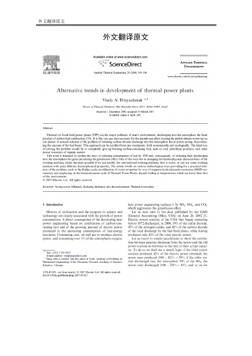
外文翻译原文外文翻译译文热电厂发展的趋势摘要热电厂是人类环境的主要污染源,其燃烧的化石燃料能产生二氧化碳并释放到大气中。
而正是这种气体产生温室效应造成全球变暖。
对于这个问题根本的解决方法是通过节约能源减少燃料燃烧进而减少二氧化碳的排放。
这种方法从经济上和生态上都是合理的,最理想的方法是完全禁止化石燃料的燃烧,如煤,石油产品以及其他自然界的有机物。
本研究试图概括出热电厂减少能源消耗进而减少温室气体的排放的方法,其中一种是改变工作介质的热力学特性。
如果我们能改变传统的工作介质的话,这种方法是可能的,如:水或者其他不同热力学特性的工作介质。
本文详细介绍了几种技术来解决这一问题,如Kalina循环,水压永磁发电机共振来修饰水的特性,使水在热电厂热循环的沸点低于环境的沸点。
引言人类文明和科学技术的发展史总是与能源消耗的增长密切联系。
热能工程发展和电力产生的增多的直接结果是能源燃料的消耗的增多。
消耗煤石油天然气来发电,同时消耗了大气中约1%的氧气,并产生二氧化硫氮氧化物和二氧化碳从而加重了温室效应。
现在我们来看看2002年美国会计学会发布的资料。
美国的发电厂从1972开始排放至2000年,排放了59%的二氧化硫,47%的氮氧化物,42%的二氧化碳,却只产生了总电力的42%。
让我们通过简单的计算比较新旧热电厂气体排放从而估计他们的实际单位效能。
首先我们要建立一个简单的逻辑:如果旧电厂产生42%的电量,那么新电厂产生了58%;如果旧电厂排放了59%的二氧化硫到大气中,则新电厂41%,其他气体以此类推。
那么每产生1%的电力就会产生1.405%的二氧化硫及其他气体。
下表列出了气体排放与电力产生比的表格。
新电厂二氧化硫和氮氧化物排放少于旧电厂,更值得比较的是,二氧化碳这种产生热能的气体。
因为含碳燃料氧化燃烧后都会生成二氧化碳。
这说明了为什么过去30年内找不到减少二氧化碳排放的根本方法,而二氧化碳是造成地球温室效应和全球变暖主要原因。
6.1‟s most efficient speed is usually much higher than that of the machine it is driving ,so a speed reduction gear usually has to be used .600 000马力的汽轮机。
转子——叶轮上装有动叶,转子两端装有轴颈。
轴承箱——安装在气缸上,用来支承转子的轴。
调速器和阀门系统——通过控制蒸汽流量来调节涡轮的速度和出力,同时还有轴承润滑系统以及一套安全装置。
某种类型的联轴器——用来连接从动机械…catch ‟the steam from the nozzle smoothly ,and they are curved so that they change the direction of the jet and in so doing receive an impulse which pushes6.1(见原文)所示为一种简单的冲动式汽轮机。
…reaction ‟ turbine .moving blades are also nozzles ,similar to the stationary nozzles but facing the other way ,and in addition to catching and deflecting the steam issuing from the stationary(见原文中图6.2)它综合了冲力和反作用力的原理。
6.2中的涡轮壳带有一整圈喷嘴,这些喷嘴和反冲式涡轮机里的一样,也是弯曲的,并以最有效的角度引导蒸汽喷向转动的叶片。
,under these conditions the exhaust volume flow becomes large ,and it is necessary to have more than one exhaust stage ;for example ,a large turbine may have three are“axial flow ”turbine .“double flow ”.drops can damage the blades and reduce the turbine efficiency ,and this is one reason why the steam ,after passing through the high-pressure turbine ,idea sometimes。
Unit2:An atom’s nucleus can be……原子核可以分裂,当这种分裂发生时,巨大的能量就会释放出来。
这是一股发热发光的能量。
爱因斯坦曾说过微小质量的物体包含巨大的能量。
当这种能量缓慢释放时,就可以利用它产生动力发电。
当这种能量瞬间释放时,就如原子弹一样产生巨大的爆炸。
A nuclear power plant……核电站用铀作为燃料。
铀是一种能从世界上的许多地方挖出的元素。
它被加工成小丸装入伸进核反应堆的长棒中。
The word fission means to……裂变一词意思就是分裂。
在核电站的反应堆内部,铀原子以可拉链式反应进行分裂。
In a chain reaction……在链式反应中,原子分裂释放的粒子离开并且撞击正在分裂的其它铀原子。
在核电站的链式反应中,那些分裂产生的粒子继续分裂其它的原子,控制棒用来使这种分裂受控因此这种分裂就不会进行得太快。
Unit3Continued research has made renewable……不断的研究使现在可再生能源的利用比25年前更能支付得起。
但是对于可再生能源的利用仍有一些缺点。
For example, solar thermal energy……例如,通过收集器收集太阳光来得到太阳能需要大量的占地面积来安装收集器。
这会影响生态环境,也就是会影响当地的动植物。
当建筑物、道路、输电线和变压器建造时,环境也会受到影响。
通常太阳能电站所用的流体大多数是有毒的而且泄露可能会发生。
Solar or PV cells……太阳能或光伏电池使用相同的技术生产电脑硅芯片。
生产过程使用了有毒的化学药品。
有毒的化学药品用来制造电池储存太阳电能来渡过黑夜和阴天。
制造这种装置也会有环境影响。
Also,even if we……即使我们想马上转换太阳能,仍然存在很大的问题。
世界上所有的太阳能生产设备使太阳能电池满载也只能产生大约350MW,大约够一个300000人口的城市使用,相对我们的需求而言那是微不足道的。
热能与动力工程毕业设计文献翻译文献翻译题目生水源热泵空调系统学生姓名专业班级热能与动力工程08-1 学号院(系)机电工程学院指导教师(职称)完成时间生水源热泵空调系统Yong Cho , Rin YunA K-Water Institute, Korea Water Resources Corporation, 462-1, Jeonmin-dong, Daejeon305-730, Republic of KoreaB Department of Mechanical Eng., Hanbat National Univ., Duckmyung-dong, San 16-1, Daejeon 305-719, Republic of Korea摘要生水源是很有发展前景的新热源之一,研究人员正在将生水源和其他水源(如地面水、湖泊水、河流水和污水)一起作为研究对象。
一般来说,取于环境再供给水质处理设备的水就叫做生水。
在这个课题中,利用供给水质处理设备的生水热能来工作的热泵机组的制冷和制热性能还有待研究。
每两个被测的热泵的热容量为65.2KW,并且通常安置在加热或制冷的控制中心房间。
可以运用焊接的金属板接收来自于生水源的热能。
除了春季,与周围的空气源相比,生水源能够提供良好的热源。
在春秋季节,加热和制冷的负荷极低,因此,生水源热泵系统在这些季节表现不佳。
关键词生水源/热泵/加热和制冷/部分负荷性能1.引言水源有很多种,像地面水,湖泊水,河水,污水和生水。
生水是这些很有发展前景的热源之一。
一般来说,这种水取于环境再通过大型的管道进入水质处理设备来进行后续处理或净化。
像那种没有经过处理的水源就叫做生水。
被调往多个区域供水系统的生水通过各种渠道的运输流动是产生巨大温差的来源。
在这个研究项目中,生水被当作热泵系统的热源来完成水质处理设备整合操作中心的加热和冷却过程。
在实际生活中我们很难找到可以把生水当作热源的相似或相近的操作系统。
文献翻译题目生水源热泵空调系统学生姓名专业班级热能与动力工程08-1 学号院(系)机电工程学院指导教师(职称)完成时间生水源热泵空调系统Y ong Cho , Rin Y unA K-Water Institute, Korea Water Resources Corporation, 462-1, Jeonmin-dong, Daejeon305-730, Republic of KoreaB Department of Mechanical Eng., Hanbat National Univ., Duckmyung-dong, San 16-1,Daejeon 305-719, Republic of Korea摘要生水源是很有发展前景的新热源之一,研究人员正在将生水源和其他水源(如地面水、湖泊水、河流水和污水)一起作为研究对象。
一般来说,取于环境再供给水质处理设备的水就叫做生水。
在这个课题中,利用供给水质处理设备的生水热能来工作的热泵机组的制冷和制热性能还有待研究。
每两个被测的热泵的热容量为65.2KW,并且通常安置在加热或制冷的控制中心房间。
可以运用焊接的金属板接收来自于生水源的热能。
除了春季,与周围的空气源相比,生水源能够提供良好的热源。
在春秋季节,加热和制冷的负荷极低,因此,生水源热泵系统在这些季节表现不佳。
关键词生水源/热泵/加热和制冷/部分负荷性能1.引言水源有很多种,像地面水,湖泊水,河水,污水和生水。
生水是这些很有发展前景的热源之一。
一般来说,这种水取于环境再通过大型的管道进入水质处理设备来进行后续处理或净化。
像那种没有经过处理的水源就叫做生水。
被调往多个区域供水系统的生水通过各种渠道的运输流动是产生巨大温差的来源。
在这个研究项目中,生水被当作热泵系统的热源来完成水质处理设备整合操作中心的加热和冷却过程。
在实际生活中我们很难找到可以把生水当作热源的相似或相近的操作系统。
接下来我们将会对与之相关的现存的处理水源热泵和地源热泵系统的方法进行一些简单的研究。
Nam和Ooka利用地下水和空气建立了双源混合热泵系统。
在春秋季节,水源热泵系统并没有比基于地下水和周围环境之间温差的空气源热泵有效。
研究数据表明,根据实验,开发的混合系统与水冷却系统相比有2%到7%的改善,与空气源热泵相比有4%到18%的改善。
在另外相关的一个研究中,Nam 等人研究了地下水源热泵的性能。
这种系统主要依赖于水的温度及深度,并且实验表明其效能比空气源热泵要高的多。
Yu 和他的同事调查了上海一家档案馆的地源热泵系统,这个档案馆的房间终年可以保持在相对恒定的温度和相对湿度条件下。
在这个研究中,利用废热来加热空气处理机组中的剩余空气的方法是很有名的。
春秋季节的能效系数要比夏季和冬季分别低42%和14%。
但是,这种地源热泵的运营代价比空气源热泵降低了55.8%。
此外,Chen 等人调查了中国北京一幢很高的公寓大楼的下面的地下水源热泵,通过对这个系统进行的两年的分析研究,他们建立了有效的操作方法和控制算法。
Koo 等人调查了现场实验的地源热泵的制热性能。
结果表明,平均的季节性加热能效比为5.1,部分负荷条件下为46.9%。
同时,包括热泵和风机能耗在内的季节性系统COP 才只有4.2。
这个研究的目的是测定运用提供给水处理设备的生水热能的热泵的制冷和制热性能。
2.实验和数据处理图1显示了在南韩Chung-ju 安装的水处理设备的生水源热泵系统。
来自南韩Daechong 水库的生水经由换热量为151.2KW 的板式换热器给自来水源热泵系统提供热源。
这种热能输送给在热泵和板式换热器之间循环并且作为制冷系统载冷剂的盐水。
表1显示了热泵系统的各种性能参数。
两套热泵系统的安装位置如图1所示。
系统的制冷量和制热量分别是58KW 和65.2KW 。
该系统所用的制冷剂是R410A ,并且机组包括有三个压缩机,一个是变容积的卷轴式压缩机,另外两个是稳定速度的卷轴式压缩机。
这种压缩机的内部单元是片匣式的,并且嵌入在水净化系统操作中心的天花板上。
当所需的加热和制冷负荷低于正常的系统容量时,压缩机的部分片匣将会是关闭的。
表2显示了系统所用的测量工具和测量误差。
电阻式温度检测传感器包括了一个PT-100Ω仿真器和一个电阻式温度校准仪,这种传感器的测量误差是±0.1℃。
,unit sys hp sys q q cop cop w w == (1)h p c o mp w w w =+ (2) sys hp pupmw w w =+ (3)c p h pq m c T w =∆- (4) h p h pq m c T w =∆- (5) 生水源热泵系统的整体性能可以用COP 值来估算,方程用(1)中定义了单位和系统的COP 值。
单位COP 仅用包括压缩机和换热器风机在内的热泵系统功率消耗来定义。
来源于压缩机和风机运转损失的热泵功耗如方程(2)所示。
包括压缩功率在内的系统COP 如方程(3)所示。
系统的制热量和制冷量用方程(4)所示。
因为这个估算方程中测量的是室外的机组,加热制冷量要加上或除去压缩功。
已经考虑到所有不确定因素影响的系统COP 值可以用和的平方根来计算。
经估算,系统的平均不确定度为16.8%±。
表1 热泵系统的规格规格容量和类型 冷却能力58kw 室内干湿球温度 27度/19.5度 加热能力水温和流量(20度/1901/min ) 65.2kw 冷却压缩机 室内干球温度(20度) 水温和流量(20度/1901/min )数码涡旋压缩机+固定速度卷轴压缩机换热器类型R410A 钎板式换热器 原水流量 1901/min表2 测量仪器的规格温度+/-0.1度 流量 10.2-741.9升/分钟正负1%全尺寸图1 安装在水处理设备的生水源热泵机组原理图2 生水源热泵系统仿真流程图图3 空气源热泵仿真流程图3.生水源热泵仿真生水源热泵仿真建模是用来研究系统的特性,并且空气源热泵是的模型是为了和水源热泵相比较。
图2显示了生水源热泵模型的计算程序,图3是空气源热泵的程序。
对于生水源热泵的建模设计,蒸发温度是用对数平均温差计算,用迭代的方法决定的,然后蒸发器的进口处性能可以由膨胀装置进口处和蒸发器进口处的焓值的差值以及蒸发器进口处制冷剂的蒸发特性估算。
节能减排要求提高系统的能源效率。
为此,可再生能源技术在不断发展。
空间加热和冷却热泵是一个使人感兴趣的的例子。
为了使他们更直观的表现,即定义了性能系数或能效比,为低温加热和冷却高温作业要求。
另一方面,一个合适的源或汇的温度是必要的。
通常情况下,使用外部空气,但在这方面能表现受气候变化情况的影响。
如果可用,并允许,地下水是最优的,它的恒温条件很稳定。
另一种可能是以地面作为热源,因为它的温度几乎一年固定,从而使双方在加热和冷却季节比外部空气的温度变化小。
在这种情况下,压缩机的功耗和它的等熵效率是一定的,压缩功可以从实验或厂商处获得。
起初要先假设等熵效率,再视系统的性能而定。
因为加热和制冷的负荷在春秋季节极低,得到不同的等熵效率值对于解释这些季节条件下的生水源热泵操作系统的模型仿真系统是很有必要的。
在全负荷的条件下,压缩机的等熵效率只有0.85,全负荷条件下的各种数据均可以由厂商提供,冷凝温度和在该温度下的冷凝压力是已经给定的。
部分负荷条件下的等熵效率要由以下因素决定。
部分负荷下的冷凝温度和全负荷下冷凝温度的要保持一致。
蒸发器的进口处温度要在一个合理的范围内即过热温度要在合理的范围内,过高或过低的吸所温度都会对压缩的性能产生不良影响。
考虑到包括压缩机功耗在内的操作条件影响下,在部分负荷只有10%时,压缩机的等熵效率是0.5。
这个极低的负荷可以清晰的显示出与全负荷条件下系统工作性能的差别。
表3 蒸发器模型的输入变量输入参数水源热泵 空气源热泵 UA(KW/K)13.0 8.0 能量(KW)60 60 温度(℃)8.15 5.3 空气流量(CMM) N/A 250空气源热泵系统建模目的主要集中于确定某一环境温度下的蒸发器温度。
蒸发器模型输入信息如表3。
蒸发器容量用方程(5)计算。
估算量要用改变蒸发温度和给定量相比较的方法来校准,直到它们之间的误差在某一个给定的范围内。
在室外空气温度的计算中,系统的潜热可以忽略。
空气的温度是用来计算得到方程(1)中的对数平均温差。
水源热泵的国际标准是13KW/K,空气源热泵的标准是8.0KW/K 。
水源热泵的国际标准要依照其安装位置,并且可以从厂商提供的系统性能数据中直接得到。
热源温度则要由测量数据得到。
根据傅立叶定律:evap lm Q U A T =∆ (5)4.结果和讨论图4显示了生水温度和周围空气温度从2010年一月到十二月的日平均变化。
图5显示了空气和水温的月平均变化。
从十二月到次年五月为需要制冷的季节,从六月到九月则是需要制热的季节。
在从十月到次年五月的加热季节里,生水温度比空气的温度高4.9℃。
在需要制冷的季节里,自来水温度比空气的温度低3.6℃。
就春季的系统性能来说,环境温度下的蒸发温度更有利。
因为生水源的温度数据很有限,所以在图4和5给定热源温度的基础上比较水源热泵和空气源热泵的性能是很有益的。
表6显示了不同热源在不同加热条件下R410A仿真模型的结果。
冷凝温度在制热时通常会控制在一个确定的温度,而模型的建立主要集中于确定给定的某一温度热源的蒸发温度。
基于这种模型,实验得出的数据显示空气源热泵的能耗要比水源热泵的高28%。
冷凝器的制热量在两个系统中是一样的,因此COP的差别是和压缩机的功耗成比例的。
另外和水源热泵系统相比,较低的温度和较小的国际标准是低蒸发温度的两个特点。
图4 一月到十二月水和空气的温度图5 1-12月水和空气平均温度变化图6 制热工况下不同热源的仿真循环图7表明了实验的季节性COP 变化。
加热季节的单位COP 范围是从一月到三月,由2.0到4.0减少。
生水源热泵系统的COP 由生水温度和系统的载荷比决定。
载荷比的方程如(6)所示。
min actual ratio no al Q Load Q (6)一到三月份性能系数的下降趋势可能源于机组中部分系统载荷的上升。
从三月到五月,负载的比率变得极低,最低可以达到10%左右,在此期间,比率并未有显示出变化的迹象。
然而,在这期间水温如图4所示持续增加,而这些正是系统的性能系数增加的主要原因。
在十月到十二月的供暖季节,生水温度下降,负荷载显著增加。
这两个加在性能系数平衡性上的影响仅仅会导致性能系数的微小变化。
而在制冷季节,单位性能系数的变化范围在4.5-8之间,这在负载最高的七月和八月是最高的。
平均单位性能系数在供热季是3.3,而平均性能系数在供冷季节是7.2。