Digi【ZigBee】XBee2详细技术资料
- 格式:pdf
- 大小:1.28 MB
- 文档页数:78

XBee和XBee-PRO OEM RF模块的设计,以ZigBee协议内运作,支持低成本的独特需求,低功耗无线传感器网络工程。
模块只需要最小的功率,就能提供远程设备之间的数据传输的可靠性。
这两个模块内运作的ISM2.4GHz频段,且引脚对引脚相互兼容。
1.1主要特点XBee XBee-PRO高性能、低成本室内/城市:距离100'(30米)户外线的视线:300'(100米)发射功率:1毫瓦(0dBm时)接收灵敏度:-92dBm的室内/城市:300'(100米)户外线的视线:高达1英里(1500米)发射功率:100毫瓦(20dBm的)的EIRP 接收灵敏度:-100dBm的射频数据传输速率:250,000个基点低功率TX电流:45毫安(@3.3伏)RX电流:50毫安(@3.3伏)掉电电流:<10微安TX电流:215毫安(@3.3伏)RX电流:55毫安(@3.3伏)掉电电流:<10微安先进的网络和安全重试和确认。
DSSS(直接序列扩频)每一个序列频道,可使用超过65000个唯一的网络地址点至点,点对点,点对多点和点对点的对等拓扑支撑自行安排,自我修复和故障容错网络易于使用没有配置必要的外箱射频通信AT和API命令模式配置模块参数小尺寸广泛的命令集免费的X-CTU软件(测试和配置软件)免费及无限技术支持1.1.1.全球认证FCC认证(美国)参见附录A[p34要求]。
系统包含的XBee/XBee-PRO射频模块继承MaxStream的认证。
ISM(工业,科学和医疗)2.4吉赫频带的ISO9001:2000认证机构认证下制造的注册标准的XBee/XBee-PRO射频模块列表被优化用于在美国,加拿大,澳大利亚,以色列和欧洲。
1.2.描述表1-01,XBee/XBee‐PRO OEM RF模块(简述)描述xbee XBee-PRO性能室内和城市的范围距离30M距离100米室外的可视范围距离100m距离1500米发射功率输出(软件可选)1mW(0dBm)60mW(18dBm)conducted,100mW(20dBm)EIRP*射频数据速率250,000bps250,000bps串行接口数据速率(软件可选)1200-115200bps(标准的传输速率,也支持非标准)1200-115200bps(标准的传输速率,也支持非标准)接收器灵敏度-92dBm(1%的错误包)-100dBm(1%的错误包)电源要求电源电压 2.8–3.4V 2.8–3.4V工作电流(发送)45mA(@3.3V)If PL=0(10dBm):137mA(@3.3V),139mA(@3.0V)PL=1(12dBm):155mA(@3.3V),153mA(@3.0V)PL=2(14dBm):170mA(@3.3V),171mA(@3.0V)PL=3(16dBm):188mA(@3.3V),195mA(@3.0V)PL=4(18dBm):215mA(@3.3V),227mA(@3.0V)工作电流(接收)50mA(@3.3V)55mA(@3.3V)掉电电流不支持不支持概要操作频段ISM2.4GHz ISM2.4GHz尺寸0.960”x1.087”(2.438cm x2.761cm)0.960”x1.297”(2.438cm x3.294cm)工作温度-40to85o C(industrial)-40to85o C(industrial)天线选择集成带,芯片或U.FL连接器集成带,芯片或U.FL连接器网络与安全支持的网络拓扑点至点,点对多点,对等网络与网孔通道数量(软件可选)16个直接序列通道16个直接序列通道寻址选项PAN编号,通道和地址PAN编号,通道和地址机构认证美国(FCC15.247部分)OUR-XBEE OUR-XBEEPRO加拿大工业部(IC)4214A XBEE4214A XBEEPRO欧盟ce ETSI ETSI(Max.10dBm transmit poweroutput)*当在欧洲运用时:XBee-PRO RF模块必须被配置为运行在一个最大发射功率为10dBm的输出水平。

Getting Started GuideXBee ZNet 2.5 ZigBee® Mesh Development KitIntroductionRange Test Setup Node Discovery Create long-range wireless links in minutes!IntroductionThis Getting Started Guide provides step-by-step instruction on how to set up a networkand test the modules' ability to transport data over varying ranges and conditions. This guide illustrates how to discover all nodes in your network and set parameters to run a Range Test.Range Test SetupRequired Components(1) XBee ZNet 2.5 COORDINA TOR (XB24-BWIT-002)(At least 1) XBee ZNet 2.5 ROUTER/END DEVICE (XB[P]24-BxIT-004).(1) USB Interface Board* (XBIB-U-DEV) (for interfacing between an RF module & host PC)(1) RS-232 Interface Board (XBIB-R-DEV) (for looping data back to the base from a remote)(1) PC (Windows 2000 or XP) with an available USB (or RS-232*) port. Required installations:X-CTU Software & USB drivers.Accessories (1 USB Cable, 1 Serial Loopback Adapter [RED] & 1 power supply)* XBee ZNet 2.5 Development Kits (XB24-BPDK) contain three RS-232 interface boards. An RS-232 board (w/RS-232 cableand power supply) can be used in lieu of the USB board.Software Installations Install X-CTU SoftwareSelect the “Range Test” tab.Click the 'Start' button to begin the range test.COORDINATOR to nd the maximum range of the wireless link. The percentage of good/bad packets will be displayed in the "Percent" box. [Figure 5] 5. 4. 6. Move the ROUTER/END DEVICE (with red Serial Loopback Adapter) away from theyou are communicating with out of range of the COORDINATOR. Power anotherROUTER/END DEVICE between the COORDINATOR and the out of range ROUTER/END DEVICE to reestablish communications. Messages are now being routed through the new 7. Change the Loopback Adapter to any other ROUTER/END DEVICE and repeat steps 1-6 if desired.8. Mesh networking capabilities can be observed by moving the ROUTER/END DEVICE thatROUTER/END DEVICE.Contact Digi International(O ce hours are 8am – 5pm U.S. Mountain standard time)Range TestX-CTU is a stand-alone tool for con guring XBee modules. It is used to run the range test and is included in the Hardware and Software Setup CD. X-CTU can also be found on the website at /support/productdetl.jsp?pid=3352&osvid=57&tp=4&s=316.To install X-CTU:1. Insert the Hardware and Software Setup CD in the PC’s CD/DVD drive.2. On the Home page, click Modules, Sensors, & Adapters Documentation Software.3. Click XBee Module.4. Click Install X-CTU.5. When installation completes, start X-CTU by selecting: Start>Programs>Digi>X-CTU. The X-CTU interface is opened.address has been entered with the ATDH and ATDL parameters from the COORDINATOR. 3.The Serial Loopback Adapter should be placed on the ROUTER/END DEVICE whose 64-bit[Figure 4]* The 64-bit address is physically printed on each XBee module (see white label attached to the shield on the bottom).Run Range Test (continued)Toll-free phone U.S.A. & Canada: (866) 765-9885 Worldwide: (801) 765-9885Live chat: Online support: /support/eservice/login.jspFigure 5PN (1P): 90000862-88 B4a. (Optional) Check the “RSSI” checkbox to enable the Received Signal Strength Indicator.Software Installations (continued)Node DiscoveryDiscovery of All Nodes in a Network1. Mount XBee modules to theUSB & RS-232 development boards.The module mounted to the USBboard should be theCOORDINAThe modules mounted to theRS-232 boards are all ROUTER/END DEVICES (XB[P]24-BxIT-004).2.Connect the U.FL (snap-on) and RPSMA(threaded) antennas to the appropriateXBee modules.3.C onnect power supplies and poweron all other radios.4.Under the “PC Settings” tab select theCOM port to which yourCOORDINATOR is attached. Also selectBaud: 9600Flow Control: HardwareData Bits: 8Parity: NONEStop Bits: 1.NOTE: If the COORDINATOR is powered on, as the other radios are turned on,their red LEDs will blink at a rate of twice per second, indicating they have joined the network.Range TestUse the “Terminal” and “Range Test”tabs of the X-CTU Software to:• Set parameters on the COORDINATOR module to communicate with a speci c ROUTER/END DEVICE• Determine the range capabilities of the XBee ModulesThe USB interface board is a “plug-and-play” device that should be detected by the PC automatically. To interface between the USB interface board and a PC, two drivers must be installed: a USB driver and a virtualCOM port driver that makes the USB port look and perform like a physical COM port. After the modem is detected, a wizard for installing the USB driver is launched. The USB driver is includedon the Hardware and Software Setup CD.Use the following steps to install the two USB drivers:1. Connect the XBee to a PC using a USB cable. The Found New Hardware Wizarddialog box is displayed.2. Verify that the Hardware and Software Setup CD is inserted into the drive.3. Select Install from a speci c list or location (Advanced), and then click Next.4. Select Search for the best driver in these locations and search removable media(CD-ROM). Click Next. A Hardware Installation Windows Logo Testing alert box is displayed.5. Click Continue Anyway.6. Click Finish.7. You will be prompted to install another driver, the virtual COM port driver. Repeatsteps 3 through 6 to install this driver.TOR (XB24-BWIT-002).6. From X-CTU, while in command mode (command mode will automatically be exited with 10 secondsof inactivity), enter the ATND command followed by a carriage return. All powered ROUTERS/END DEVICES that have joined the network will respond with their device information.The second eld returned from the ATND parameter is the 64-bit address of each particularROUTER/END DEVICE. [Figure 2]1.Follow the directions in the previous example to perform a Node Discovery.2. Use the ATDH and ATDL commands to set the destination address high and the destinationaddress low of the COORDINATOR to match the 64-bit address of the particular ROUTER/END DEVICE with which you wish to communicate. Use ATDH for the upper 32 bits and ATDLfor the lower 32 bits of the 64-bit address. [Figure 3] The “Modem Con guration” tab can beused to do this as well.R un Range TestFigure 164-bit address(i.e., 8 bytes, 16 characters)Figure 2Upper and Lower 32 bitsof 64-bit addressFigure 3Install USB Drivers5. On the Terminal tab, enter command mode. This mode eliminates over-the-air communications for the XBee module, and allows internal communication with the XBee module parameters.If command mode is entered, an OK message is displayed. There is a one-second “guardtime” before and after entering command mode, and a ten-second timeout.To enter command mode, enter +++ with no carriage return. [Figure 1]。

本文旨在帮助初次使用Digi公司的XBee无线模块快速熟悉产品和操作配置方法。
模块操作以Zigbee协议为例,其它无线协议方法类似,具体请查看相关模块的产品说明书。
在使用过程中,如果疑问或发现错误的地方,请联系当地代理商技术支持,或直接联系robin.tu@。
一、使用前的准备工作XBee模块产品按协议和频率,传输能力的不同,共有数十种。
大多数XBee模块产品的串口引脚和电源引脚均相同,可以直接替换。
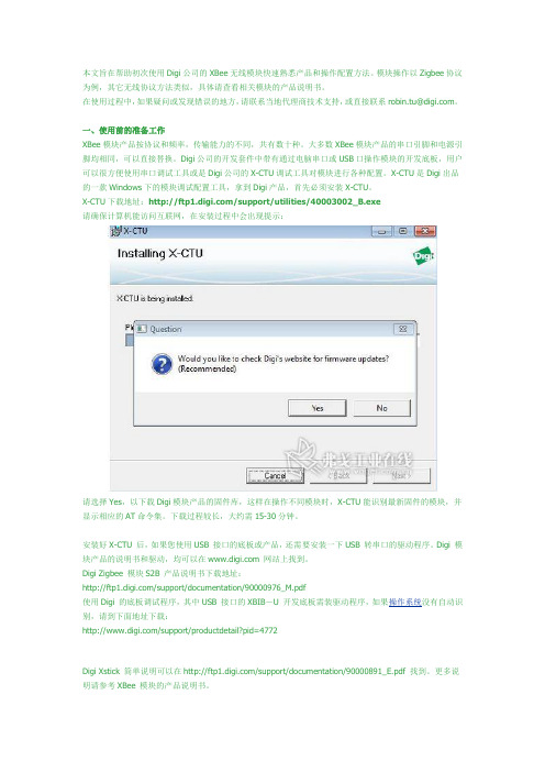
Digi公司的开发套件中带有通过电脑串口或USB口操作模块的开发底板,用户可以很方便使用串口调试工具或是Digi公司的X-CTU调试工具对模块进行各种配置。
X-CTU是Digi出品的一款Windows下的模块调试配置工具,拿到Digi产品,首先必须安装X-CTU。
X-CTU下载地址:/support/utilities/40003002_B.exe请确保计算机能访问互联网,在安装过程中会出现提示:请选择Yes,以下载Digi模块产品的固件库,这样在操作不同模块时,X-CTU能识别最新固件的模块,并显示相应的AT命令集。
下载过程较长,大约需15-30分钟。
安装好X-CTU 后,如果您使用USB 接口的底板或产品,还需要安装一下USB 转串口的驱动程序。
Digi 模块产品的说明书和驱动,均可以在 网站上找到。
DigiZigbee模块S2B 产品说明书下载地址:/support/documentation/90000976_M.pdf使用Digi的底板调试程序,其中USB 接口的XBIB-U 开发底板需装驱动程序,如果操作系统没有自动识别,请到下面地址下载:/support/productdetail?pid=4772DigiXstick简单说明可以在/support/documentation/90000891_E.pdf 找到。
更多说明请参考XBee模块的产品说明书。
Xstick需要FT232R USB 转串口驱动,请下载合适的操作系统驱动:/Drivers/VCP.htm/Drivers/VCP/Linux/ftdi_sio.tar.gz安装好驱动后,将模块产品接上电脑,打开X-CTU ,在PC Settings 标签下,就可以看到对应的串口,就可以对模块进行AT 命令或API 命令帧方式操作。
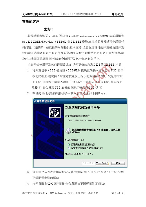
尊敬的客户:您好!非常感谢您购买kyzf829(网店为,QQ:604914729)所销售的DIGI XBEE-PRO-S2、XBEE-S2等ZIGBEE模块,在以后的开发过程中遇到任何问题,我都将一如既往的对您提供技术支持.当您收到我司的开发模块或开发包后请首选确认是否所有附件都齐全,如果差什么附件势必影响您的开发进度,请及时与我司联系调换.附件清单会随同开发包一起送到您手上.当您开始使用开发包前请阅读此文,以便更快的熟悉DIGI的ZIGBEE产品:1.将开发包中XBEE模块或XBEE-PRO模块正确插入开发包中USB接口板的底板上(模块插入时注意按底板上标识的方向插入)将开发包中附带的USB连接线一端接入微机USB口,另一端接入开发包USB接口板的USB口,您会发现USB底板的电源灯被点亮(USB供电)2.微机提供找到新的硬件并要求插入驱动光盘,如下图所示:3.请选择“从列表或指定位置安装”并指定到“CH340T驱动”下一步”完成下载配置电缆的驱动4.打开桌面上”X-CTU”图标,你会发现如下图所示界面(图2)就说明您的USB下载电缆没有驱动,请重复3,4;一、以点对点无线传输1.在X-CTU软件里面选择”modem configuration”,然后再在”modem”下将模块选成:XB24-ZB或XBP24-ZB(分别对应ZIGBEE的XBEE模块和XBEE-PRO模块),在”Function set”下将功能选成”zigbee coordinaor at”,然后将DH和DL(目的地址)设成另一模块的地址,点击”write”完成这个模块的配置.如图所示:2.拔掉USB线,取下配置好的模块,将开包中另一块XBEE或XBEE-PRO插入USB底板, 在X-CTU软件里面选择”modem configuration”,然后再在”modem”下将模块选成:XB24-ZB或XBP24-ZB(分别对应2.4G的XBEE模块和XBEE-PRO模块),在”Function set”下将功能选成”zigbeerouter at”,并将DH和DL(目的地址高位和目的地址低位)设置成COORDINA TOR的地址,点击”write”完成这个模块的配置.如图所示:3.将先前配置好的XBEE或XBEE-PRO模块插入开发包中串口底板上,并接入开发包配套电源适配器(将此模块移到一定远的地方)4.打开X-CTU,并用USB线接上一块已经配置好的模块,选中”RANGETEST”点击开始就可以看到有数据发出,并可以看到数据发送(绿色)灯闪烁.如果远端的模块可以收到数据的话您可以看到数据接收灯(黄色)闪烁.旁边的三个绿灯用于表示信号强弱.在远端的串口底板上接上开发包附带串品回环器(红色并注有loop back).您会看到数据通过无线发送后又通过远端模块串口回传到XCTU的接收窗口.如图所示二、点对多点实验过程1.将模块A插入USB接口底板,打开XCTU软件进入”modem configuration”,先选拔您所用模块型号(XBEE:XB24-ZB;XBEE-PRO:XBP24-ZB)然后在”Function set”里选择:” zigbee coordinaor at”将A模块作为”广播端”那么您还需要修改A的地址如下:DH(Destination address high):0000DL(Destination address low):FFFFMY(16-bit source address):0 (A模块)“WRITE”完成BASE也就是广播端的参数设置.2.同样的办法将模块B,C,D,E,F….设置成如下地址(如果您打算将B,C,D,E,F….模块设成远端也就是被广播端)DH(Destination address high):0000DL(Destination address high):0000MY(16-bit source address):1(B模块)MY(16-bit source address):2(C模块)MY(16-bit source address):3(D模块)………“WRITE”完成对所有”REMOTE”也就是远端模块参数的设置3.将所有模块插在底板上,”REMOTE”端需都加上串口回环,开发包只带一个回环器,回环不够可用一根导线将串口DB9的2,3脚短路,通电!4.将配置好的BASE模块A插入USB接口板,打开XCTU软件,选中”TERMINALàAssemble packet”,正常情况下,在空白窗口输入一串字母”Send data”(蓝色)会收到几个相同字母(红色),完成一个点发送多点接收并回环的实验.如图:三、MESH网配置测试方法:1.将任意一块XBEE,XBEEPRO模块A插入USB接口底板.2.打开XCTU软件进入”Modem configuration-àModem”选择您所用模块型号:XB24-ZB或XBP24-ZB3.在”Function set”中选择” Zigbee coordinator A T”将您的模块A配置成网络协调器.并设置一个”node identifier”比如:C.最后”WRITE”完成4.同样的办法将另外的几个模块配置成:ROUTER.主要不同是”functionset”选择为” ZIGBEE ROUTER A T”配置一个”Node identifier”比如:R1,R2.最后”WRITE”完成.5.将各模块分别插入底板,将”Coordinator”模块A插入USB底板并打开XCTU软件的”Terminal”,在空白窗口依次输入如下命令:“+++”返回”OK”/进入A T命令集/“A TND”返加各个ROUTER的相应信息/寻找同一PAN网中所有ROTER/“A TDN R1”返回ROUTER1的相应地址等信息/与R1建立物理连接/如图6.之后便可以数据传输.注意接收转发的R1需将串口回环接上.7.在”range test”下做数据据传输接收实验了.8.测试中间路由功能.将R1慢慢放到一个无法接收到数据的距离,再将R2放到R1和网络协调器中间.正常情况下R1会通过R2与Coordinator通讯.关掉R2的电源,R1又无法与Coordinator连接.以此证明路由功能.您也可以多级联几级,但最多不能超过6级.9.结束测试”+++”注意查阅数据手册上关于A T指令的功能说明。
ZigBee用于工程的最佳选择——XBee/XBeePRO1.ZigBee概述ZigBee是给予无线通信标准的一个名称,基本上为工业应用而开发的。
从历史角度来看,ZigBee改良早前称为“Home RF”的标准,该标准起初前景一片光明,可是因著竞争对手Wireless Fidelity(Wi-Fi)标准的成功,它就被废弃了。
Home RF寿命如此短促,至少发人深醒,也教人忧虑,是否历史不断在重复之中。
然而,可保证这个想法是莫须有的,因为ZigBee由主要的参与者如Freescale(此乃Motorola的子公司)、Honeywell、Philips、Microchip 及Mitsubishi等所支援,并且联同大约一百家其他制造商组成名为“ZigBee Alliance”的财团。
ZigBee原是依据于IEEE 802.15.4标准,并且采用与Wi-Fi同一频带(2.4GHz),它有16个分开的频道,换言之在单一位置上可提供多达16个网络而不会互相干扰。
最大数据传输速率为250Kb/s (在100米范围内),相比于Wi-Fi的54Mb/s或BlueTooth的1MB/s,此数据速率实在是很低了,可视之为ZigBee的弱点。
可是,正如先前提到,这协议原意用作工业用途,在速度上不是主要考虑的。
ZigBee是为满足低电流损耗和尤其是低成本需求而开发的。
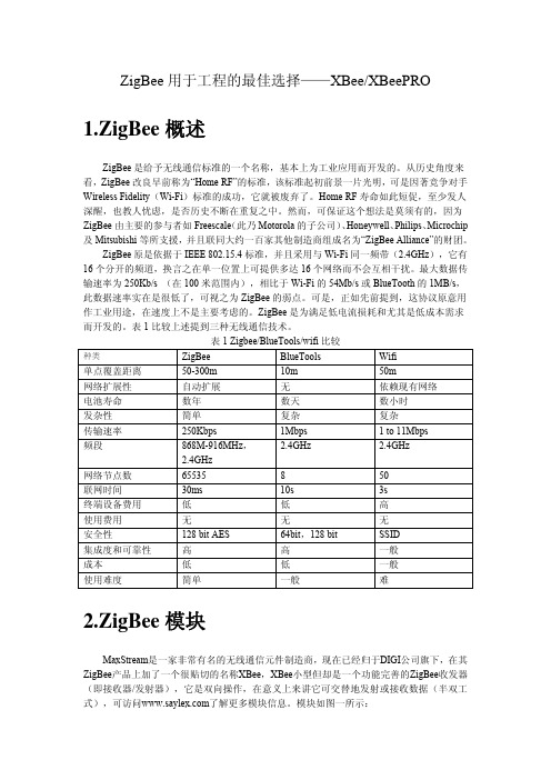
表1比较上述提到三种无线通信技术。
表1 Zigbee/BlueTools/wifi比较Wifi 种类ZigBee BlueTools单点覆盖距离 50-300m 10m 50m网络扩展性自动扩展无依赖现有网络电池寿命数年数天数小时发杂性简单复杂复杂传输速率250Kbps 1Mbps 1 to 11Mbps2.4GHz 2.4GHz 频段 868M-916MHz,2.4GHz网络节点数 65535 8 50联网时间 30ms 10s 3s终端设备费用低低高使用费用无无无安全性128 bit AES 64bit,128 bit SSID集成度和可靠性高高一般成本低低一般使用难度简单一般难2.ZigBee模块MaxStream是一家非常有名的无线通信元件制造商,现在已经归于DIGI公司旗下,在其ZigBee产品上加了一个很贴切的名称XBee,XBee小型但却是一个功能完善的ZigBee收发器(即接收器/发射器),它是双向操作,在意义上来讲它可交替地发射或接收数据(半双工式),可访问w 了解更多模块信息。
1. XBEE DigiMesh RF 模块介绍● 具有重发和ACK 确认 ● 自路由,自愈合MESH ● DSSS● 不需要配置RF 通信● 通过AT 和API 命令来进行模块参数配置 ● 小封装 管脚定义 1 VCC 电源2 DOUT 输出 UART 数据输出3 DIN/CONFIG 输入 UART 数据输入4 DIO12双向数据I/O5RESET输入或开漏输出模块复位(复位脉冲至少100us ,必须使用开漏驱动,当复位发生时模块将其下拉,则此信号线将无法拉高)6 PWM0/RSSI/DIO10 双向 PWM 输出0/RX 信号强度指示/数据IO7 PWM/DIO11 双向 PWM 输出1/数字IO 11 8NCNCXBee XBee-PRO 灵敏度 -92dBm -100dBm 发射功率 0dBm 20dBm 接收电流 50mA 55mA发射峰值电流 45mA250/340mA (RPSMA ) 掉电电流(周期睡眠) <50uA 掉电电流(管脚休眠)<10μA 波特率 1200~250k bps 供电电压 2.8~3.4V网络拓扑 MESH ,点对点,点对多点,peer-to-peer 信道数 16个直接序列信道12个直接序列信道地址特性 PAN ID ,信道和64位地址加密 128bit AES9 DIR/SLEEP_RQ/DIO8 双向管脚休眠控制线或数字IO810 GND 电源地11 AD4/DIO 4 双向模拟输入4或数字IO412 CTS/DIO7 双向CTS流程控制或数字IO713 ON/SLEEP输出模块状态指示或数字IO914 VREF ——如果需要模拟IO采样,此信号线必须连接为2.6V到VCC之间。
15 辅助指示/DIO5/DIO6 双向副指示,数字IO516 RTS/DIO6 双向RTS流程控制,数字IO617 AD3/DIO3 双向模拟输入3或数字IO318 AD2/DIO2 双向模拟输入3或数字IO219 AD1/DIO1 双向模拟输入1或数字IO120 AD0/DIO0/commissioning双向模拟输入0,数字IO0,commissioning button button设计注意:●最少连接方式:VCC,GND,DOUT&DIN●固件升级最少连接方式:VCC,GND,DOUT,DIN,RTS&DTR●指定模块的信号方向●模块内部在RESET管脚上附加了50kΩ的上拉电阻●可以通过PR命令将若干输入配置为上拉●不用的管脚要悬空XBee模块并不一定要求外围电路,也不需要特殊连接。
国外进口模块:XBee产品评测及组网应用ZigBee是一种低功耗、短距离无线标准,在家用自动化设备和工业控制等领域有着广泛应用前景。
ZigBee原是依据于IEEE802.15.4标准,并且采用与Wi-Fi同一频带(2.4GHz),它有16个分开的频道,换言之在单一位置上可提供多达16个网络而不会互相干扰。
最大数据传输速率为250Kb/s (在100米范围内)。
MaxStream是一家非常有名的无线通信元件制造商,现在已经归于DIGI公司旗下,在其ZigBee产品上加了一个很贴切的名称XBee,XBee小型但却是一个功能完善的ZigBee收发器(即接收器/发射器),它是双向操作,在意义上来讲它可交替地发射或接收数据(半双工式)。
XBee实测特性:(XBee/XBee-PRO)XBee功能强大,同时与其他RF无线通行模块相比,其设置和应用却又更为简单易学。
XBee具备诸多功能特性,其单点覆盖距离跟据其版本不同,输出功率不同而不同,从1mw~50mw不等距离从0~1600m。
具备自动网络扩展功能,联网时间短,仅30ms即可完成。
下面小编简单的介绍一下如何使用XBee组网使用。
小编建立了一个简单的网络关系:(其中com5、com7工作于End device模式(CE=0),com3、com8工作于coordinator模式(CE=1)。
com5指定传输目标位com7的工作地址(DH+DL=(COM7的MYADDRESS)),com7工作于可向组网传输数据的终端工作模式(A1=4)。
com3和com8工作于组网互传数据模式(A2=7)。
其他设置包括PAN ID、channel等都保持默认未作修改。
工作模式通过AT指令进行设定,操作较为简单易学,用户可以通过自身项目需要建立相应的网络数据传输关系。
)(每个串口各发了一条信息,并同时通过串口监视各个com端接受的情况。
蓝色字体即表示发送的数据,红色字体即表示接收到的数据。
XBee S2C DigiMesh2.4Kit Radio Frequency(RF)ModuleSet up your XBee devices Step1:Assemble the hardware StepMake sure the board is NOT powered by either the micro USB or a battery when youplug in the XBee module.WARNING!Never insert or remove the XBee device while the power is on!Set up your XBee devices Step2:Download and install XCTUAfter you plug the XBee module into the board,connect the board tomicro USB cables provided.Ensure the loopback jumper is in the UART position.Make sure the board is not powered when you remove the XBee module.StepSet up your XBee devices Step2:Download and install XCTUStepbutton.button.select the7.Click Add selected devices once the discovery process has finished.You should see something similar to the following example in the Radio Modules section:8.Click Finish.button. XBee SMT Grove Development Boardbutton.button.initials in the Search boxexample:button.button. button.Check the networkOnce both XBee modules are configured,use XCTU to check that they are in the same network and can see each other.1.Click the Discover radio nodes in the same network button of XBEE_A.The device searches for devices in the same network.When the discovery process is finished,XCTU lists discovered devices found within the network in the Discovering remote devices dialog.2.Click Cancel.There is no need to add the remote device that has been discovered.Send messages through XCTUUse the XCTU console to have your two XBee modules send messages to each other.1.Switch both XBee modules to the consoles working mode.2.Open a serial connection for each XBee.a.Select XBEE_A and click.b.Select XBEE_B and click.button toopen forStep4:Create a mesh networkThis section describes how to add a third XBee module to create a mesh network.Establish a meshnetwork any time you want to create a network that is larger than the range of each individual device.In these instructions,you first connect a loopback jumper to an XBee module in preparation fortesting your network.If you get stuck,see Troubleshooting.Connect a loopback jumper to an XBee moduleConnecting a loopback jumper to an XBee module lets you send a message to another XBee moduleand have the message loop back to the sender.1.Connect the loopback jumper on XBEE_B so it bridges the pin marked"loopback"and themiddle pin on its development board.2.In the XBEE_A console,click the Clear session button to clear your previous conversation.3.Type"Hello!"Each character loops back in the XBEE_A console log,which indicates that XBEE_A successfullysent the message to XBEE_B.You are now ready to use the loopback jumper to help you test a mesh network consisting ofthree XBee modules.Set up a third XBee module to create a mesh networkTo create a mesh network,move XBEE_B away from XBEE_A until communication is lost.Then,add XBEE_C to relay messages between XBEE_A and XBEE_B.The network automatically adjusts and redirects communications when a pathway becomes available.1.Move XBEE_B out of range of XBEE_A:a.Disconnect XBEE_B from your computer and remove it from XCTU by clicking theRemove the list of remote modules button.b.Connect XBEE_B to a power supply(or laptop or portable battery)and move it awayfrom XBEE_A until it is out of range.The approximate indoor range is100ft(30m),and the approximate outdoor rangeis300ft.(90km).c.Make sure the loopback jumper is connected to XBEE_B.See Connect the loopbackjumper.d.In the XBEE_A console,click to clear your previous conversation with XBEE_B.e.Type"Are you out of range?"In the illustration below,the message does not loopback,which means XBEE_B did not receive it and it is out of range of XBEE_A.f.If the message loops back,move XBEE_B farther away until it no longer loops back.2.Add and configure another XBee module:a.Connect another XBee module to your computer.b.Click the Configuration working modes button.c.Click the Add a radio module button.d.In the Add a radio module dialog,select the USB Serial Port for this XBee moduleand click Finish.e.Configure this XBee module as follows:ID:D161NI:XBEE_Cf.Click the Write radio settings button.XBEE_B:mode.removebutton.insteadtoBefore you perform other tasks,change the loopback jumper on XBEE_B so it no longer bridges the two pins on its development board.It should look like this:Step5:Use API mode to talk to XBee modulesThis section shows you how to configure an XBee module in API mode,which gives you flexibility,speed,and reliability in your data transmissions.If you get stuck,see Troubleshooting.For more information on API mode,see the XBee S2C DigiMesh2.4User Guide.Configure an XBee module in API mode1.Select XBEE_A and click the Configuration working modes button.2.Add this configuration:AP:API Mode13.Click the Write radio settings button.The Port indicates XBEE_A is in API mode.Send an API Tx frame from an XBee module to another moduleAPI Tx frames are the instructions that allow one XBee module to send data to another XBee module.In these instructions,XBEE_A uses the API frame type"Transmit Request"to send some text data to XBEE_B.1.Reconnect XBEE_B to your computer.2.Make sure the loopback jumper on XBEE_B no longer bridges the two pins on its developmentboard.3.In XCTU, rediscover XBEE_B.4.Switch XBEE_A and XBEE_B to console mode:a.Select XBEE_A and click.Then click to open a serial connection.b.Select XBEE_B and click.Then click to open a serial connection.5.Select XBEE_A.6.In the Send a single frame area,click the Add new frame to the list button.7.In the Add API frame to the list dialog,click the Create frame using'Frames Generator'tool button.8.In the XBee API Frame generator dialog,configure the following parameters:Protocol:DigiMeshMode:API1Frame type: 0x10-Transmit Request64-bit dest.address:MAC address of XBEE_BRF data:Type"Hello XBee_B!"in the ASCII tab9.Click OK.10.In the Add API frame to the list dialog,type a name for your frame.11.Click Add frame.12.In the Send frames area,make sure your frame is selected.13.In the Send a single frame area,click Send selected frame.14.In the Frames log area,select Transmit Request and then Transmit Status to look at theFrame details for each.For example,select Transmit Status and scroll down in the Frame details area to see that your Delivery status is a success.15.In the Radio Modules area,select XBEE_B."Hello XBee_B!"appears in the Console log.Do more with your XBee devices Update the firmware of your XBee modules Update the firmware of your XBee modulesRadio firmware is the program code stored in the device's persistent memory that provides thecontrol program for the e XCTU to update the firmware.1.Click the Configuration working modes button.2.Add local and remote XBee modules to your computer.See Add XBee modules to XCTU andConfigure remote XBee modules.3.Select a local or remote XBee module from the Radio Modules list.4.Click the Update firmware button.The Update firmware dialog displays the available and compatible firmware for the selectedXBee module.5.Select the product family of the XBee module,the function set,and the latest firmware version.6.Click Update.A dialog displays update progress.Configure remote XBee modulesYou can communicate with remote devices over the air through a corresponding local device.Configure the local device in API mode because remote commands work only in API mode.Configure remote radio modules in either API or transparent mode.These instructions show you how to configure the LT(Associate LED blink times)parameter on aremote module.Do more with your XBee devices Configure remote XBee modules1.Add two XBee modules to XCTU.See Add XBee modules to XCTU.2.Configure the first XBee module in API mode and name it XBEE_A.See Configure an XBeemodule in API mode.3.Configure the second XBee module in either API or transparent mode,and name it XBEE_B.See Configure the first two XBee modules in transparent mode.4.Disconnect XBEE_B from your computer and remove it from XCTU by clicking the Remove thelist of remote modules button.5.Connect XBEE_B to a power supply(or laptop or portable battery).Your Radio Modules area should look something like this.6.Select XBEE_A and click the Discover radio nodes in the same network button.7.Click Add selected devices in the Discovering remote devices dialog.The discovered remotedevice appears below XBEE_A.8.Select the remote device XBEE_B,and configure the following parameter:LT:FF(hexidecimal representation for2550ms)9.Click the Write radio settings button.The remote XBee module now has a different LED blink time.10.To return to the default LED blink times,change the LT parameter back to0for XBEE_B.Set up and perform a range testThis section shows you how to set up two XBee modules to perform a range test,which demonstrates the real-world RF range and link quality between two XBee modules in the same network.Performinga range test gives an initial indication of the expected communication performance of the kitcomponents.When deploying an actual network,perform multiple range tests to analyze varyingconditions in your application.Configure the XBee modules for a range testFor XBee modules to communicate with each other,you configure them so they are in the samenetwork.You also set the local device to API mode to obtain all possible data of the remote XBeemodule.1.Add two XBee modules to XCTU.See Step3:Add the XBee modules to XCTU.2.Select the first XBee module and click the Load default firmware settings button.3.Configure the following parameters:ID:D161NI:XBEE_AAP:API enabled[1]4.Click the Write radio settings button.5.Select the other XBee module and click.6.Configure the following parameters:ID:D161NI:XBEE_BAP:API disabled[0]button.computer button.work in menu and window opens.2.Select XBEE_A and click the Discover remote devices button.The discovery of remote devices starts.When the discovery process finishes,the other device (XBEE_B)appears in the Discovering remote devices dialog.3.Click Add selected devices.4.Select XBEE_B from the Discovered device drop-down menu in the Device Selection area.5.For Range Test type,select Cluster ID0x12.6.Click the Start Range Test button.7.If a notification dialog asks you to close the loopback jumper in the remote device,click OK.8.Test the signal interference by doing one of the following:n Place your hands over one of the XBee modules.n Block line-of-sight with your body.n Place a metal box over an XBee module.n Move the remote XBee module to a different room or floor of the building.The Received Signal Strength Indicator(RSSI)value will decrease and some packets may even be lost.9.Observe how XCTU represents the retrieved data:n Range Test chart represents the RSSI values of the local and remote devices during the range test session.The chart also shows the percentage of total packets successfullysent.n Local and Remote bar graphs represent the signal strengths of the local and remote XBee modules.These values are retrieved for the last packet sent/received.RSSI ismeasured in dBm.A greater negative value in dBm indicates a weaker signal.Therefore,-50dBm is better than-60dBm.n Packets sent and Packets received area shows the total number of packets sent, packets received,transmission errors,and packets lost.The percentage bar graphindicates the percentage of packets that are successfully sent and received during arange test session.In the following illustration,the percentage of packets successfully sent is69%and received is 64%.The actual percentage of packets successfully sent or received may be higher.10.Click the Stop Range Test button to stop the process at any time.11.When you have completed the range test,click the Remove the list of remote modulesbutton to remove the remote XBee modules from XCTU.Troubleshooting Cannot find the serial port for the module Cannot find the serial port for the moduleYou can remove the XBee Grove Development Board from the USB port and view which port name no longer appears in your port list.The name that no longer appears is your XBee board.To use XCTU to determine the correct serial port:1.Open XCTU,Click the Discover radio modules button.2.Select all ports to be scanned.3.Click Next and then Finish.Once the discovery process completes,a new window notifies you of the devices discovered and the details.The serial port and the baud rate appear in the Port label.Cannot identify XBee modulesTo identify modules you have added to XCTU,read the device settings of each module and check the Rx and Tx LEDs of the XBee Grove Development Boards.The LEDs indicate that the XBee module isreceiving(Rx)or transmitting(Tx)information through the serial port.When you read or write the settings of a module,the Rx and Tx LEDs blink so you can identify whichmodule is connected to each serial port.The following example shows the LED for a port already inuse.The serial port where the local XBee module is connected can only be in use by one application.Check to make sure the connection with the module in the XCTU console is closed and there are no otherapplications and no other instances of XCTU using the port.Cannot install device driverThe device driver software was not successfully installed.Potential causeSometimes when you connect an XBee Grove board to your computer,the operating system does not install the driver.Troubleshooting Use LEDs to identify XBee modulesResolutionTry the following,in order.If one of the steps resolves the issue,you're done.1.Remove and re-insert the XBee module into your computer.2.If the OS is still unable to install the driver,remove and re-insert the XBee module into anotherUSB port.3.If your computer fails during the driver initialization problem and you are still unable to installthe drivers,complete the following steps:a.Open the Device Manager.b.In the Other Devices section,right-click on the device T232R USB UART and clickuninstall.c.Plug in your device and allow your system to reinstall the drivers.Use LEDs to identify XBee modulesYou want to force LEDs to blink so you can easily locate an XBee module.ResolutionTo locate an XBee module using LEDs:1.In XCTU,select one of your XBee modules and click the Read radio settings button.2.Observe which XBee module has the Rx and Tx LED lights blinking green and yellow on itsdevelopment board.No remote devices to select for a range testIf there are no remote XBee modules to select in the Radio Range Test dialog,try one of the following resolutions.Check cablesThe USB cables should be firmly and fully attached to both the computer and the XBee development board.When attached correctly,the association LED on the adapter is lit.Check that the XBee module is fully seated in the XBeedevelopment boardWhen the XBee module is correctly installed,it is pushed fully into the board and no air or metal isvisible between the plastic of the adapter socket and the XBee module headers.Also,check that all ten pins on each side of the XBee module are in a matching hole in the socket.Check the XBee module orientationThe angled"nose"of the XBee module should match the lines on the silk screening of the board and point away from the USB socket on the XBee development board.Troubleshooting Port in usePortXCTU cannot discover devicesIf XCTU doesn't discover an XBee module or doesn't display any serial ports,try the followingresolutions.Check the configuration of your USB serial converter1.On the Start menu,click Computer>System Properties>Device Manager.2.Under Serial Bus controllers,double-click the first USB Serial Converter to open the USB SerialConverter dialog.3.Click the Advanced tab,make sure Load VCP is selected,and click OK.4.Repeat steps2and3for each USB Serial Converter listed in the Device Manager.Check cablesDouble-check all cables.The USB cable should be firmly and fully attached to both the computer and the XBee development board.When attached correctly,the association LED on the adapter will be lit.Check that the XBee module is fully seated in the XBeedevelopment boardWhen the XBee module is correctly installed,it should be pushed fully into the board and no air ormetal should be visible between the plastic of the adapter socket and the XBee module headers.Also, double-check that all ten pins on each side of the XBee module made it into a matching hole in thesocket.Check the XBee module orientationThe angled"nose"of the XBee module should match the lines on the silk screening of the board and point away from the USB socket on the XBee development board.Check that the XBee modules are in the same networkCheck that the Network ID(ID)and the Channel(CH)settings have the same value for both XBeemodules.Check driver installationDrivers are installed the first time the XBee development board is plugged in.If this process is notcomplete or has failed,see Cannot install device driver.Check if the modules are sleepingThe On/Sleep LED of the Grove Development Board indicates if the XBee module is awake(LED on)or asleep(LED off).When an XBee module is sleeping,XCTU cannot discover it,so press the Commissioning button to wake it up for30seconds.XBee TH Grove Development BoardXBee SMT Grove Development BoardCheck the loopback jumperThe loopback jumper should not be connected when XCTU is trying to find the module.Make sure the loopback jumper is not connected to the loop-back pins.defaultbutton. In theandRegulatory information Europe(CE) Europe(CE)The XBee S2C DigiMesh2.4Kits have been tested for European compliance and CE markedaccordingly,refer to /resources/certifications.If the XBee S2C DigiMesh2.4Kits are incorporated into a product,the manufacturer must ensurecompliance of the final product with articles3.1a and3.1b of the Radio Equipment Directive2014/53/EU.An EU Declaration of Conformity must be issued in accordance with the Radio Equipment Directive2014/53/EU and supplied with the product when it is placed on the European market.A copy of the EU Declaration of Conformity must also be kept on file as described in the Radio EquipmentDirective.Furthermore,the manufacturer must maintain a copy of the XBee S2C DigiMesh2.4Kit user manual documentation and ensure the final product does not exceed the specified power ratings,antennaspecifications,and/or installation requirements as specified in the user guide.Maximum power and frequency specificationsFor the through-hole device:n Maximum power:9.82mW(9.92dBm)Equivalent Isotropically Radiated Power(EIRP)at normal condition.n Frequencies:5MHz channel spacing,beginning at2405MHz and ending at2480MHz.For the surface-mount device:n Maximum power:12.65mW(11.02dBm)EIRP.n Frequencies:5MHz channel spacing,beginning at2405MHz and ending at2480MHz.。
355 South 520 West, Suite 180Lindon, UT 84042Phone: (801) 765-9885Fax: (801) 765-9895rf-xperts@ (live chat support)XBee™ Series 2 OEM RF ModulesXBee Series 2 Series 2 OEM RF Modules ZigBee ™ Networks RF Module Operation RF Module Configuration AppendicesProduct Manual v1.x.2x - ZigBee ProtocolFor OEM RF Module Part Numbers:XB24-BxIT-00xZigBee OEM RF Modules by MaxStream, Inc. - a Digi International brand Firmware Versions:1.0xx - Coordinator , Transparent Operation 1.1xx - Coordinator , API Operation1.2xx - Router , End Device, Transparent Operation 1.3xx - Router , End Device, API Operation90000866_B 2007.07.019© 2007 Digi International, Inc. All rights reservedNo part of the contents of this manual may be transmitted or reproduced in any form or by any means without the written permission of Digi International, Inc. ZigBee® is a registered trademark of the ZigBee Alliance.XBee™ Series 2 is a trademark of Digi International, Inc.Technical Support: Phone: (801) 765‐9885Live Chat: E‐mail: rf‐xperts@Contents1. XBee Series 2 OEM RF Modules41.1. Key Features 41.1.1. Worldwide Acceptance 41.2. Specifications 51.3. Mechanical Drawings 61.4. Mounting Considerations 61.5. Pin Signals 71.6. Electrical Characteristics 82. RF Module Operation92.1. Serial Communications 92.1.1. UART Data Flow 92.1.2. Serial Buffers 92.1.3. Serial Flow Control 102.1.4. Transparent Operation 122.1.5. API Operation 122.2. Modes of Operation 132.2.1. Idle Mode 132.2.2. Transmit Mode 132.2.3. Receive Mode 142.2.4. Command Mode 142.2.5. Sleep Mode 153. ZigBee Networks173.1. ZigBee Network Formation 173.1.1. Starting a ZigBee Coordinator 173.1.2. Joining a Router 173.1.3. Joining an End Device 183.2. ZigBee Network Communications 193.2.1. ZigBee Device Addressing 193.2.2. ZigBee Application-layer Addressing 193.2.3. Data Transmission and Routing 204. XBee Series 2 Networks254.1. XBee Series 2 Network Formation 254.1.1. Starting an XBee Series 2 Coordinator 254.1.2. Joining an XBee Series 2 Router to an ex-isting PAN 254.1.3. Joining an XBee Series 2 End Device to anExisting PAN 254.1.4. Network Reset 264.2. XBee Series 2 Addressing 274.2.1. Device Addressing 274.2.2. Application-layer Addressing 294.2.3. XBee Series 2 Binding Table 294.2.4. XBee Series 2 Endpoint Table 314.3. Sleep Mode Operation 324.3.1. End Device Operation 324.3.2. Parent Operation 324.4. I/O Line Configuration 325. Advanced Features355.1. Device Discovery 355.2. Remote Configuration 355.3. Loopback Testing 355.3.1. AT Firmware 355.3.2. API Firmware 355.4. Join Indicators 355.5. Manual Device Identification 355.6. Battery Life Monitoring 366. XBee Series 2 Command Reference Tables377. API Operation437.0.1. API Frame Specifications 437.0.2. API Frames 448. Examples568.0.1. Starting an XBee Network 568.0.2. AT Command Programming Examples 578.0.3. API Programming Examples 579. Manufacturing Support599.1. Interoperability with other EM250 Devic-es 599.2. Customizing XBee Default Parameters599.3. XBee Series 2 Custom Bootloader 599.4. Programming XBee Series 2 Modules 599.5. XBee EM250 Pin Mappings 59 Definitions 61Agency Certifications 63Migrating from the 802.15.4 Protocol 67 Development Guide 68Additional Information 781. XBee Series 2 OEM RF ModulesThe XBee Series 2 OEM RF Modules were engineered to operate within the ZigBee protocol and support the unique needs of low-cost, low-power wireless sensor networks. The modules require minimal power and provide reliable delivery of data between remote devices.The modules operate within the ISM 2.4 GHz frequency band.1.1. Key Features1.1.1. Worldwide AcceptanceFCC Approval (USA) Refer to Appendix A [p50] for FCC Requirements.Systems that contain XBee Series 2 RF Modules inherit MaxStream Certifications.ISM (Industrial, Scientific & Medical) 2.4 GHz frequency band Manufactured underISO 9001:2000 registered standardsXBee Series 2 RF Modules are optimized for use in US , Canada , Australia, Israel and Europe (contact MaxStream for complete list of agency approvals).High Performance, Low Cost•Indoor/Urban: up to 133’ (40 m)•Outdoor line-of-sight: up to 400’ (120 m)•Transmit Power: 2 mW (+3 dBm)•Receiver Sensitivity: -96 dBm RF Data Rate: 250,000 bps Advanced Networking & Security Retries and AcknowledgementsDSSS (Direct Sequence Spread Spectrum)Each direct sequence channel has over65,000 unique network addresses available Point-to-point, point-to-multipoint and peer-to-peer topologies supported Self-routing, self-healing and fault-tolerant mesh networkingLow Power XBee Series 2•TX Current: 40 mA (@3.3 V)•RX Current: 40 mA (@3.3 V)•Power-down Current: < 1 µA @ 25o C Easy-to-UseNo configuration necessary for out-of box RF communicationsAT and API Command Modes for configuring module parameters Small form factor Extensive command setFree X-CTU Software(Testing and configuration software)Free & Unlimited Technical Support1.2. Specifications*The ranges specified are typical when using the integrated Whip (1.5 dBi) and Dipole (2.1 dBi) antennas. The Chipantenna option provides advantages in its form factor; however, it typically yields shorter range than the Whip and Dipole antenna options when transmitting outdoors. For more information, refer to the “XBee Series 2 Antenna” application note located on MaxStream’s web site/support/knowledgebase/article.php?kb=153Table 1‐01.Specifications of the XBee Series 2 OEM RF ModuleSpecification XBee Series 2Performance Indoor/Urban Range up to 133 ft. (40 m)*Outdoor RF line-of-sight Range up to 400 ft. (120 m)*Transmit Power Output (software selectable)2mW (+3dBm), boost mode enabled 1.25mW (+1dBm), boost mode disabled RF Data Rate250,000 bpsSerial Interface Data Rate (software selectable)1200 - 230400 bps(non-standard baud rates also supported)Receiver Sensitivity -96 dBm, boost mode enabled -95 dBm, boost mode disabledPower Requirements Supply Voltage2.1 -3.6 VOperating Current (Transmit, max output power)40mA (@ 3.3 V, boost mode enabled)35mA (@ 3.3 V, boost mode disabled)Operating Current (Receive))40mA (@ 3.3 V, boost mode enabled)38mA (@ 3.3 V, boost mode disabled) Idle Current (Receiver off) 15mA Power-down Current < 1 uA @ 25o C GeneralOperating Frequency Band ISM 2.4 GHzDimensions0.960” x 1.087” (2.438cm x 2.761cm)Operating Temperature -40 to 85º C (industrial)Antenna Options Integrated Whip, Chip, RPSMA, or U.FL Connector*Networking & Security Supported Network Topologies Point-to-point, Point-to-multipoint, Peer-to-peer & Mesh Number of Channels (software selectable)16 Direct Sequence ChannelsAddressing Options PAN ID and Addresses, Cluster IDs and Endpoints (optional)Agency ApprovalsUnited States (FCC Part 15.247)OUR-XBEE2Industry Canada (IC)4214A-XBEE2Europe (CE)ETSI1.3. Mechanical DrawingsFigure 1‐01.Mechanical drawings of the XBee Series 2 OEM RF Modules (antenna options not shown).1.4. Mounting ConsiderationsThe XBee Series 2 RF Module (through-hole) was designed to mount into a receptacle (socket) and therefore does not require any soldering when mounting it to a board. The XBee Series 2Development Kits contain RS-232 and USB interface boards which use two 20-pin receptacles to receive modules.Figure 1‐02.XBee Series 2 Module Mounting to an RS ‐232 Interface Board .The receptacles used on MaxStream development boards are manufactured by CenturyInterconnect. Several other manufacturers provide comparable mounting solutions; however , MaxStream currently uses the following receptacles:•Through-hole single-row receptacles -Samtec P/N: MMS-110-01-L-SV (or equivalent)•Surface-mount double-row receptacles -Century Interconnect P/N: CPRMSL20-D-0-1 (or equivalent)•Surface-mount single-row receptacles - Samtec P/N: SMM-110-02-SM-SMaxStream also recommends printing an outline of the module on the board to indicate the orientation the module should be mounted.XBee1.5. Pin SignalsFigure 1‐03.XBee Series 2 RF Module Pin Number (top sides shown ‐ shields on bottom)Design Notes:•Minimum connections: VCC, GND, DOUT & DIN•Minimum connections to support serial firmware upgrades: VCC, GND, DIN, DOUT , RTS & DTR •Signal Direction is specified with respect to the module •Module includes a 30k Ohm resistor attached to RESET•Several of the input pull-ups can be configured using the PR command •Unused pins should be left disconnectedTable 1‐02.Pin Assignments for the XBee Series 2 Modules(Low ‐asserted signals are distinguished with a horizontal line above signal name.)Pin #Name DirectionDescription 1VCC -Power supply 2DOUT Output UART Data Out 3DIN / CONFIG Input UART Data In 4DIO12Either Digital I/O 125RESET Input Module Reset (reset pulse must be at least 200 ns)6PWM0 / RSSI / DIO10Either PWM Output 0 / RX Signal Strength Indicator / Digital IO7PWM / DIO11Either Digital I/O 118[reserved]-Do not connect9DTR / SLEEP_RQ/ DIO8Either Pin Sleep Control Line or Digital IO 810GND -Ground 11DIO4Either Digital I/O 412CTS / DIO7Either Clear-to-Send Flow Control or Digital I/O 713ON / SLEEP / DIO9Output Module Status Indicator or Digital I/O 914[reserved]-Do not connect15Associate / DIO5Either Associated Indicator, Digital I/O 516RTS / DIO6 Either Request-to-Send Flow Control, Digital I/O 617AD3 / DIO3Either Analog Input 3 or Digital I/O 318AD2 / DIO2Either Analog Input 2 or Digital I/O 219AD1 / DIO1Either Analog Input 1 or Digital I/O 120AD0 / DIO0 / ID ButtonEitherAnalog Input 0, Digital I/O 0, or Node Identification1.6. Electrical CharacteristicsTable 1‐03.DC Characteristics of the XBee Series 2 (VCC = 2.8 ‐ 3.4 VDC)Symbol Parameter Condition Min Typical Max Units V IL Input Low Voltage All Digital Inputs-- 0.2 * VCC V V IH Input High Voltage All Digital Inputs0.8 * VCC- 0.18* VCC V V OL Output Low Voltage I OL = 2 mA, VCC >= 2.7 V--0.18*VCC V V OH Output High Voltage I OH = -2 mA, VCC >= 2.7 V0.82*VCC--V II IN Input Leakage Current V IN = VCC or GND, all inputs, per pin--0.5uA uA2. RF Module Operation2.1. Serial CommunicationsThe XBee Series 2 OEM RF Modules interface to a host device through a logic-level asynchronous serial port. Through its serial port, the module can communicate with any logic and voltage compatible UART; or through a level translator to any serial device (For example: Through a MaxStream proprietary RS-232 or USB interface board).2.1.1. UART Data FlowDevices that have a UART interface can connect directly to the pins of the RF module as shown in the figure below.Figure 2‐01.System Data Flow Diagram in a UART ‐interfaced environment(Low ‐asserted signals distinguished with horizontalline over signal name.)Serial DataData enters the module UART through the DIN (pin 3) as an asynchronous serial signal. The signal should idle high when no data is being transmitted.Each data byte consists of a start bit (low), 8 data bits (least significant bit first) and a stop bit (high). The following figure illustrates the serial bit pattern of data passing through the module.Figure 2‐02.UART data packet 0x1F (decimal number ʺ31ʺ) as transmitted through the RF moduleExample Data Format is 8‐N ‐1 (bits ‐ parity ‐ # of stop bits)The module UART performs tasks, such as timing and parity checking, that are needed for data communications. Serial communications depend on the two UARTs to be configured with compatible settings (baud rate, parity, start bits, stop bits, data bits).2.1.2. Serial BuffersThe XBee Series 2 modules maintain small buffers to collect received serial and RF data, which is illustrated in the figure below. The serial receive buffer collects incoming serial characters and holds them until they can be processed. The serial transmit buffer collects data that is received via the RF link that will be transmitted out the UART .DIN (data in)DIN (data in)DOUT (data out)DOUT (data out)XBee Series 2 OEM RF Modules ‐ ZigBee ‐ v1.x2x [2007.07.019]Chapter 2 ‐ RF Module Operation Figure 2‐03.Internal Data Flow DiagramSerial Receive BufferWhen serial data enters the RF module through the DIN Pin (pin 3), the data is stored in the serialreceive buffer until it can be processed. Under certain conditions, the module may not be able toprocess data in the serial receive buffer immediately. If large amounts of serial data are sent tothe module, CTS flow control may be required to avoid overflowing the serial receive buffer.Cases in which the serial receive buffer may become full and possibly overflow:1.If the module is receiving a continuous stream of RF data, the data in the serial receivebuffer will not be transmitted until the module is no longer receiving RF data.2.If the module is transmitting an RF data packet, the module may need to discover the des-tination address or establish a route to the destination. After transmitting the data, themodule may need to retransmit the data if an acknowledgment is not received, or if thetransmission is a broadcast. These issues could delay the processing of data in the serialreceive buffer.Serial Transmit BufferWhen RF data is received, the data is moved into the serial transmit buffer and is sent out theserial port. If the serial transmit buffer becomes full enough such that all data in a received RFpacket won’t fit in the serial transmit buffer, the entire RF data packet is dropped.Cases in which the serial transmit buffer may become full resulting in dropped RFpackets1. If the RF data rate is set higher than the interface data rate of the module, the modulecould receive data faster than it can send the data to the host.2. If the host does not allow the module to transmit data out from the serial transmit bufferbecause of being held off by hardware flow control.2.1.3. Serial Flow ControlThe RTS and CTS module pins can be used to provide RTS and/or CTS flow control. CTS flowcontrol provides an indication to the host to stop sending serial data to the module. RTS flowcontrol allows the host to signal the module to not send data in the serial transmit buffer out theuart. RTS and CTS flow control are enabled using the D6 and D7 commands.If CTS flow control is enabled (D7 command), when the serial receive buffer is 17 bytes awayfrom being full, the module de-asserts CTS (sets it high) to signal to the host device to stopsending serial data. CTS is re-asserted after the serial receive buffer has 34 bytes of space.If flow RTS control is enabled (D6 command), data in the serial transmit buffer will not be sent out the DOUT pin as long as RTS is de-asserted (set high). The host device should not de-assert RTS for long periods of time to avoid filling the serial transmit buffer. If an RF data packet is received, and the serial transmit buffer does not have enough space for all of the data bytes, the entire RF data packet will be discarded.2.1.4. Transparent OperationRF modules that contain the following firmware versions will support Transparent Mode:1.0xx (coordinator) and 1.2xx (router/end device).When operating in Transparent Mode, the modules act as a serial line replacement. All UART data received through the DIN pin is queued up for RF transmission. When RF data is received, the data is sent out the DOUT pin. The module configuration parameters are configured using the ATcommand mode interface. (See RF Module Operation --> Command Mode.)When RF data is received by a module, the data is sent out the DOUT pin.Serial-to-RF PacketizationData is buffered in the serial receive buffer until one of the following causes the data to bepacketized and transmitted:1. No serial characters are received for the amount of time determined by the RO (Packetiza-tion Timeout) parameter. If RO = 0, packetization begins when a character is received.2.Maximum number of characters that will fit (72) in an RF packet is received.3.The Command Mode Sequence (GT + CC + GT) is received. Any character buffered in theserial receive buffer before the sequence is transmitted.2.1.5. API OperationAPI (Application Programming Interface) Operation is an alternative to the default Transparent Operation. The frame-based API extends the level to which a host application can interact with the networking capabilities of the module. RF modules that contain the following firmware versions will support API operation: 1.1xx (coordinator) and 1.3xx (router/end device).When in API mode, all data entering and leaving the module is contained in frames that define operations or events within the module.Transmit Data Frames (received through the DIN pin (pin 3)) include:•RF Transmit Data Frame•Command Frame (equivalent to AT commands)Receive Data Frames (sent out the DOUT pin (pin 2)) include:•RF-received data frame•Command response•Event notifications such as reset, associate, disassociate, etc.The API provides alternative means of configuring modules and routing data at the hostapplication layer. A host application can send data frames to the module that contain address and payload information instead of using command mode to modify addresses. The module will send data frames to the application containing status packets; as well as source, and payloadinformation from received data packets.The API operation option facilitates many operations such as the examples cited below:->Transmitting data to multiple destinations without entering Command Mode->Receive success/failure status of each transmitted RF packet->Identify the source address of each received packetTo implement API operations, refer to the API Operation chapter 6.2.2. Modes of Operation2.2.1. Idle ModeWhen not receiving or transmitting data, the RF module is in Idle Mode. During Idle Mode, the RFmodule is also checking for valid RF data. The module shifts into the other modes of operationunder the following conditions:•Transmit Mode (Serial data in the serial receive buffer is ready to be packetized)•Receive Mode (Valid RF data is received through the antenna)•Sleep Mode (End Devices only)•Command Mode (Command Mode Sequence is issued)2.2.2. Transmit ModeWhen serial data is received and is ready for packetization, the RF module will exit Idle Mode andattempt to transmit the data. The destination address determines which node(s) will receive thedata.Prior to transmitting the data, the module ensures that a 16-bit network address and route to thedestination node have been established.If the 16-bit network address is not known, network address discovery will take place. If a route isnot known, route discovery will take place for the purpose of establishing a route to thedestination node. If a module with a matching network address is not discovered, the packet isdiscarded. The data will be transmitted once a route is established. If route discovery fails toestablish a route, the packet will be discarded.Figure 2‐04.Transmit Mode SequenceWhen data is transmitted from one node to another, a network-level acknowledgement istransmitted back across the established route to the source node. This acknowledgement packetindicates to the source node that the data packet was received by the destination node. If anetwork acknowledgement is not received, the source node will re-transmit the data. See DataTransmission and Routing in chapter 3 for more information.If a valid RF packet is received, the data is transferred to the serial transmit buffer2.2.4. Command ModeTo modify or read RF Module parameters, the module must first enter into Command Mode - astate in which incoming serial characters are interpreted as commands. Refer to the API Modesection for an alternate means of configuring modules.AT Command ModeTo Enter AT Command Mode:Default AT Command Mode Sequence (for transition to Command Mode):•No characters sent for one second [GT (Guard Times) parameter = 0x3E8]•Input three plus characters (“+++”) within one second [CC (Command Sequence Character) parameter = 0x2B.]•No characters sent for one second [GT (Guard Times) parameter = 0x3E8]All of the parameter values in the sequence can be modified to reflect user preferences.NOTE: Failure to enter AT Command Mode is most commonly due to baud rate mismatch. Ensure the ‘Baud’ setting on the “PC Settings” tab matches the interface data rate of the RF module. By default, the BD parameter = 3 (9600 bps).To Send AT Commands:Figure 2‐05. Syntax for sending AT CommandsTo read a parameter value stored in the RF module’s register, omit the parameter field.The preceding example would change the RF module Destination Address (Low) to “0x1F”. To storethe new value to non-volatile (long term) memory, subsequently send the WR (Write) command.For modified parameter values to persist in the module’s registry after a reset, changes must besaved to non-volatile memory using the WR (Write) Command. Otherwise, parameters arerestored to previously saved values after the module is reset.System Response. When a command is sent to the module, the module will parse and executethe command. Upon successful execution of a command, the module returns an “OK” message. Ifexecution of a command results in an error , the module returns an “ERROR” message.To Exit AT Command Mode:For an example of programming the RF module using AT Commands and descriptions of each configurable parameter, refer to the "Examples" and "XBee Series 2 Command Reference Tables" chapters.Send the 3-character command sequence “+++” and observe guard times before and after thecommand characters. [Refer to the “Default AT Command Mode Sequence” below.]Send AT commands and parameters using the syntax shown below.1. Send the ATCN (Exit Command Mode) command (followed by a carriage return).[OR]2. If no valid AT Commands are received within the time specified by CT (Command ModeTimeout) Command, the RF module automatically returns to Idle Mode.Sleep modes allow the RF module to enter states of low-power consumption when not in use. Toenter Sleep Mode, one of the following conditions must be met (in addition to the module having anon-zero SM parameter value):•Sleep_RQ (pin 9) is asserted•The module is idle (no data is transmitted or received) for the time defined by the ST (Time before Sleep) parameter .The SM command is central to setting Sleep Mode configurations. By default, sleep modes aredisabled (SM=0) and the module remains in Idle/Receive Mode. When in this state, the module isconstantly ready to respond to serial or RF activity.Zigbee Protocol: Sleep Modes Pin/Host Controlled Sleep Pin sleep puts the module to sleep and wakes it from sleep according to the state of Sleep_RQ(pin 9). When Sleep_RQ is asserted (high), the module will finish any transmit or receiveoperations, and then enter a low power state. The module will not respond to either serial or RFactivity while in sleep.To wake a module operating in pin sleep, de-assert Sleep_RQ (pin 9). The module will wake whenSleep_RQ is de-asserted and is ready to transmit or receive when the CTS line is low. When themodule wakes from pin sleep, it sends a transmission to its parent router or coordinator (called apoll request) to see if it has buffered any data packets for the end device. The module will continueto poll its parent for data while it remains awake. If the parent receives an RF data packet destinedfor one or more of its end device children, it will transmit the packet to the end device upon receiptof a poll request. See section 4.3, "Sleep Mode Operation" for more information.Cyclic SleepCyclic sleep allows modules to wake periodically to check for RF data and sleep when idle. Whenthe SM parameter is set to 4, the module is configured to sleep for the time specified by the SPparameter . After the SP time expires, the module will wake and check for RF or serial data. Tocheck for RF data, the module sends a transmission to its parent router or coordinator (called apoll request) to see if its parent has any buffered data packets for the end device. If the parenthas data for the module, the module will remain awake to receive the data. Otherwise, the modulewill return to sleep. (See section 4.3, "Sleep Mode Operation" for more information.)If serial or RF data is received, the module will start the ST timer and remain awake until the timerexpires. While the module is awake, it will continue to send poll request messages to its parent tocheck for additional data. The ST timer will be restarted anytime serial or RF activity occurs. Themodule will resume sleep when the ST timer expires.When the module wakes from sleep, it asserts On/Sleep (pin 13) to provide a wake indicator to ahost device. If a host device wishes to sleep longer than SP time or to wake only when RF dataarrives, the SN command can be used to prevent On/Sleep from asserting for a multiple of SPtime. For example, if SP = 20 seconds, and SN = 5, the On/Sleep pin will remain de-asserted(low) for up to 100 seconds.Table 2‐01.Sleep Mode Configurations (Router / End Device Firmware Only)Sleep ModeSettingTransition into Sleep Mode Transition out of Sleep Mode (wake)Characteristics Related Commands Power Consumption SM=1Assert (high)Sleep_RQ (pin 9)De-assert (0V) Sleep_RQ (pin 9)Pin/Host controlled SM < 1uA SM=4Automatictransition tosleep mode asdefined by theST parameter Transition occurs after the cyclic sleep time interval elapses. The time interval is defined by the SP (Cyclic Sleep Period)parameter. RF module wakes after a pre-determined time interval to detect if RF data is present. SM, ST, SP, SN < 1uAIn the ZigBee protocol, sleep modes are only supported on end devices. See section 4.3, "SleepMode Operation" for more information.If CTS flow control is enabled, CTS (pin 12) is asserted (0V) when the module wakes and de-asserted (high) when the module sleeps, allowing for communication initiated by the host if desired.3. ZigBee Networks3.1. ZigBee Network FormationA ZigBee Personal Area Network (PAN) consists of one coordinator and one or more routers and/orend devices. A ZigBee Personal Area Network (PAN) is created when a coordinator selects achannel and PAN ID to start on. Once the coordinator has started a PAN, it can allow router andend device nodes to join the PAN.When a router or end device joins a PAN, it receives a 16-bit network address and can transmitdata to or receive data from other devices in the PAN. Routers and the coordinator can allow otherdevices to join the PAN, and can assist in sending data through the network to ensure data isrouted correctly to the intended recipient device. When a router or coordinator allows an enddevice to join the PAN, the end device that joined becomes a child of the router or coordinator thatallowed the join.End devices, however can transmit or receive data but cannot route data from one node toanother, nor can they allow devices to join the PAN. End devices must always communicatedirectly to the parent they joined to. The parent router or coordinator can route data on behalf ofan end device child to ensure it reaches the correct destination. End devices are intended to bebattery powered and can support low power modes.Figure 3‐01.Node Types / Sample of a Basic ZigBee Network TopologyThe network address of the PAN coordinator is always 0. When a router joins a PAN, it can alsoallow other routers and end devices to join to it. Joining establishes a parent/child relationshipbetween two nodes. The node that allowed the join is the parent, and the node that joined is thechild. The parent/child relationship is not necessary for routing data.3.1.1. Starting a ZigBee CoordinatorWhen a coordinator first comes up, it performs an energy scan on multiple channels (frequencies)to select an unused channel to start the PAN. After removing channels with high detected energylevels, the coordinator issues an 802.15.4 beacon request command on the remaining, low energylevel channels. Nearby routers or coordinators that have already joined a PAN respond to thebeacon request frame with a small beacon transmission indicating the PAN identifier (PAN ID) thatthey are operating on, and whether or not they are allowing joining. The coordinator will attemptto start on an unused PAN ID and channel. After starting, the coordinator may allow other devicesto join its PAN.3.1.2. Joining a RouterWhen a router first comes up, it must locate and join a ZigBee PAN. To do this, it issues an802.15.4 beacon request command on multiple channels to locate nearby PANs. Nearby routersand coordinators that have already joined a PAN respond to the beacon request frame with a smallbeacon transmission, indicating which channel and PAN ID they are operating on. The routerlistens on each channel for these beacon frames. If a valid PAN is found from one of the receivedbeacons, the router issues a join request to the device that sent the beacon. If joining succeeds,the router will then receive a join confirmation from the device, indicating the join was successful.。