YAV Z3声音传感器(交流电压输出)
- 格式:docx
- 大小:393.80 KB
- 文档页数:4
为满足中国《电子信息产品污染控制管理办法》(信息产业部第39号令)的相关规定和要求,现对产品中有害物质,按部件分类,声明如下:在中华人民共和国境内销售的电子信息产品上将贴上有“环保使用期限”(EPuP )符号。
圆圈中的数字代表产品的正常环保使用年限。
图示:产品物质拆分表重要安全事项1. 阅读这些规定,注意所有警告,遵守这些规定。
2. 严禁在产品周围喷洒液体。
请勿在产品上方放置液体容器,如花瓶等。
可使用干布及风 枪进行清洁。
3. 注意不要形成热风循环。
按建议方法进行安装。
4. 不将产品安装在热源附近,尽可能保证环境气温在35°C 以下。
5. 接地保护,当产品接通电源时,应采取相应的接地保护措施。
6. 请保护好电源线,防止其受到踩踏或挤压,尤其要注意插头、电源插座及其连接设备处。
7. 必须按照以下开关次序来使用该产品:(开)前级-功放、(关)功放-前级。
8. 通电前必须确保供电电压符合该产品的要求。
9. 若输入信号并接超过三台功放,建议使用信号分配器,以确保输入信号不失真。
10. 不要将功放的某一个声道的输出接口接到另一个通道的输入接口。
不要将功放的输出并 联或联到另一台功放的输出接口。
11. 设计系统配置功放的时候,功放的功率应比音箱在相同阻抗下的标称功率大50%-100%, 且小心使用桥接模式。
12. 在维修功放的时候,禁止在桥接状态下将示波器的探头 连接到功放的输出端,以免损 坏功放和示波器。
13. 建议: 1) 由于输出到音箱的电流较大,建议使用质量有保证的NL4型音箱螺旋插头。
2) 多台功放使用时应计算好合适的配电,以确保达到合格的使用环境。
本产品仅适用于非热带气候条件下安全使用。
本产品仅适用于海拔2000m 以下安全使用。
请勿在通电状态下移动设备,这样极易造成设备故障或安全事故。
EX4130产品是一款全新的高效率和大功率的开关电源功放。
与之前产品相比较它在音质上有了突破性的改进,带给您的将是全新声音的享受。
Yaesu VX-3R中文说明书快捷按键使用:【TXPO】键:1.调整发射功率2.按键一秒进入设置模式。
.【DIAL拨】盘选择需要调整的项目,设置完成后可以按PTT 键来存储这个新的设置并回到普通操作状态。
注意:不要忘记把DIAL拨盘拉出来。
要调整多个参数,(如设置86项: TN FRQ) 可以按[TXPO] 键来进行其他项目调整设置。
【VOL】键:按住VOL键并调整DIAL拨盘可对音量大小进行调节【RADIO】键:1.调频收音机功能切换 1.在使用外接立体声耳机时按住一秒可选择使用立体声耳机作为接收天线【HM/RV】键:长按一秒紧急呼叫模式,机器将自动在430.000频率发送呼救信息,蓝色高亮度指示灯同时闪烁。
总复位操作:在电源关闭的状态下,按住[MODE]和[V/M]键不放,按电源键打开电源,之后按[F W]键即可复位。
储存频道删除操作:1.如果为VFO模式的话,按[v/m]键设置为内存模式。
2。
按住[f/w]键一秒钟,然后转动DIAL到要设为主频的频道,按[ ]键,频道号码就会在屏幕上闪烁。
3。
用顶部旋纽DIAL键选择到你要删除的频道,按[ ]键屏幕显示M-DEL? (是否删除?)再次按[ ]键,频道删除成功后LED将显示频道1会自动返回至其实频道。
注:1频道和常用频道不可删除!!!简要设置项目设置项目1 [ANT AM] (AM天线设置)功能: 为收听AM广播选择合适的天线。
可用参数选项: BAREXT/BARANT默认值: BAREXT内置的磁棒天线和橡胶天线两个都使用:BAREXT只使用内置磁棒天线:BARANT磁棒天线具有方向性,请旋转VX-3R机身以获得较好的接收效果。
.设置项目2 [ANT FM] (FM天线设置)功能: 为收听FM广播选择合适的天线。
可用参数选项: EXTANT/EARPHO默认值: EXTANT: 使用橡胶天线:EXTANT: 使用耳机线做天线(EAR插口为3R专门为收听立体声广播设置的耳机接口),当接收弱信号是,会有噪音。
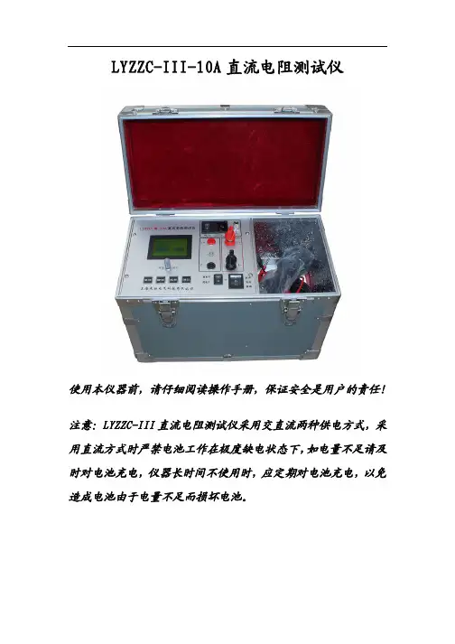
LYZZC-III-10A直流电阻测试仪使用本仪器前,请仔细阅读操作手册,保证安全是用户的责任!注意:LYZZC-III直流电阻测试仪采用交直流两种供电方式,采用直流方式时严禁电池工作在极度缺电状态下,如电量不足请及时对电池充电,仪器长时间不使用时,应定期对电池充电,以免造成电池由于电量不足而损坏电池。
一、安全措施1、使用本仪器前一定要认真阅读本手册。
2、仪器的操作者应具备一般电气设备或仪器的使用常识。
3、本仪器户内外均可使用,但应避开雨淋、腐蚀气体等场所使用。
4、仪表应避免剧烈振动。
5、对仪器的维修、护理和调整应由专业人员进行。
6、测试完毕后一定要使仪器复位后关闭电源再拆除测试线。
7、测试过程中,禁止移动测试夹和供电线路。
二、功能特点1、整机由高速单片机控制,自动化程度高,操作简便。
2、仪器采用全新电源技术,测量范围宽。
3、保护功能完善,能可靠保护反电势对仪器的冲击,性能更可靠。
4、响应速度快,仪器测量数据稳定,仪器测试过程中自动刷新数据。
6、智能化功率管理技术,仪器总是工作在最小功率状态,有效减轻仪器内部发热,节约能源。
7、仪器内部带有不掉电时钟。
8、仪器内部具有不掉电存储器,可永久保存数据。
三、技术指标1、输出电流:10A、5A、1A、200mA、40mA、<5mA2、分辨率:0.1μΩ3、量程: 100Ω-20KΩ (<5mA档)1Ω-250Ω (40mA档)100mΩ-50Ω (200mA档)5mΩ-10Ω (1A档)1mΩ-2Ω (5A档)0.5mΩ-1Ω (10A档)4、准确度:0.2%5、工作温度:0~40℃6、工作湿度:<90%RH,不结露7、外形尺寸:长325mmX宽240mmX高275mm四、系统介绍 仪器的面板见下图电 源 仪器工作电源,AC220V。
复 位 键 按下此按键本机处于初始状态,可对输出电流进行预置。
循 环 键 按此键光标在主菜单循环滚动选 择 本机复位后,按此键进行电流预置。
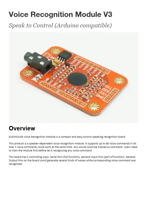
Voice Recognition Module V3 Speak to Control (Arduino compatible)OverviewELECHOUSE Voice Recognition Module is a compact and easy-control speaking recognition board.This product is a speaker-dependent voice recognition module. It supports up to 80 voice commands in all. Max 7 voice commands could work at the same time. Any sound could be trained as command. Users need to train the module first before let it recognizing any voice command.This board has 2 controlling ways: Serial Port (full function), General Input Pins (part of function). General Output Pins on the board could generate several kinds of waves while corresponding voice command was recognized.What’s new?We already have Voice Recognition module V2. It supports 15 commands in all and only 5 commands at the same time.On V2, voice commands are separated into 3 groups while you training it. And only one group (5 commands) could to be imported into Recognizer. It means only 5 voice commands are effective at thesame time.On V3, voice commands are stored in one large group like a library. Any 7 voice commands in the library could be imported into recognizer. It means 7 commands are effective at the same time.Parameter●Voltage: 4.5-5.5V●Current: <40mA●Digital Interface: 5V TTL level for UART interface and GPIO●Analog Interface: 3.5mm mono-channel microphone connector + microphone pin interface●Size: 31mm x 50mm●Recognition accuracy: 99% (under ideal environment)Feature●Support maximum 80 voice commands, with each voice 1500ms (one or two words speaking)●Maximum 7 voice commands effective at same time●Arduino library is supplied●Easy Control: UART/GPIO●User-control General Pin OutputTerminology●VR3 -- Voice Recognition Module V3●Recognizer -- a container where acting voice commands (max 7) were loaded. It is core part ofvoice recognition module. For example, it works like “playing balls”. You have 80 players in your team. But you could not let them all play on the court together. The rule only allows 7 playersplaying on the court. Here the Recognizer is the list which contains names of players working on the court.●Recognizer index -- max 7 voice commands could be supported in the recognizer. Therecognizer has 7 regions for each voice command. One index corresponds to one region: 0~6●Train -- the process of recording your voice commands●Load -- copy trained voice to recognizer●Voice Command Record -- the trained voice command store in flash, number from 0 to 79●Signature -- text comment for record●Group -- help to manage records, each group 7 records. System group and user group aresupported.InstructionHere we will introduce the Arduino Library and VR3 ProtocolFor ArduinoPrepare●Voice Recognition V3 module with microphone●Arduino board (UNO recommended)●Arduino Sensor Shield V07 (optional)●Arduino IDE●Voice Recognition V3 library (Download zip file)Hardware and Software Preparation1.Connect your Voice Recognition V3 Module with Arduino, By Default:2.Download VoiceRecognitionV3 library. (download zip file or use g i t c l o n eh t t p s://g i t h u b.c o m/e l e c h o u s e/V o i c e R e c o g n i t i o n V3.g i t command)3.If using zip file, extract VoiceRecognitionV3.zip to A r d u i n o S k e t c h\l i b r a r i e s folder, or if youuse g i t c l o n e command copy VoiceRecognitionV3 to A r d u i n o S k e t c h\l i b r a r i e s .Train1.Open vr_sample_train (File -> Examples -> VoiceRecognitionV3 -> vr_sample_train)2.Choose right Arduino board(Tool -> Board, UNO recommended), Choose right serial port.3.Click Upload button, wait until Arduino is uploaded.4.Open Serial Monitor. Set baud rate 115200, set send with Newline or Both NL & CR.5.Send command s e t t i n g s(case insensitive) to check Voice Recognition Module settings.Input s e t t i n g s, and hit E n t e r to send.6.Train Voice Recognition Module. Send s i g t r a i n0O n command to train record 0 with signature"On". When Serial Monitor prints "Speak now", you need speak your voice(can be any word, meaningful word recommended, may be 'On' here), and when Serial Monitor prints "Speak again", you need repeat your voice again. If these two voice are matched, Serial Monitor prints "Success", and "record 0" is trained, or if are not matched, repeat speaking until success.What is a signature? Signature is a piece of text description for the voice command. Forexample, if your 7 voice command are “1, 2, 3, 4, 5, 6, 7”, you could train in the following way: s i g t r a i n0o n es i g t r a i n1t w os i g t r a i n2t h r e es i g t r a i n3f o u rs i g t r a i n4f i v es i g t r a i n5s i xs i g t r a i n6s e v e nThe signature could be displayed if its command was called.When training, the two led on the Voice Recognition Module can indicate your training process.After sending the training command, the SYS_LED (yellow) is blinking fast which remind you to get ready. Speak your voice command as soon as the STATUS_LED (red) light lights on. The recording process ends once when the STATUS_LED (red) lights off. Then the SYS_LED is blinking again, get ready for next recording process. When the training process ends successful, SYS_LED and STATUS_LED blink together. If the training fails, SYS_LED and STATUS_LED blink together, but quickly.7.Train another record. Send s i g t r a i n1O f f command to train record 1 with signature "Off".Choose your favorite words to train (it can be any word, meaningful word recommended, may be'Off' here).8.Send l o a d01 command to load voice. And say your word to see if the Voice RecognitionModule can recognize your words.If the voice is recognized, you can see.9.Train finish. Train sample also support several other commands.Control LED SampleHere we show a simple example showing how to control the LED on Arduino board(connecting to pin13)through voice commands.Before this example,you need to train the VR module first in the way as vr_sample_train shows above. Use the following commands:●s i g t r a i n0o n Train the voice command used to light on the LED●s i g t r a i n0o f f Train the voice command used to turn off the LEDThen following the steps:1.Open vr_sample_control_led (File -> Examples -> VoiceRecognitionV3 ->vr_sample_control_led)2.Choose right Arduino board (Tool -> Board, UNO recommended), Choose right serial port.3.Click Upload button, wait until Arduino is uploaded.4.Open Serial Monitor. Set baud rate 115200.5.You will see the indication:Speak the voice commands you train above and check the status of LED on Arduino.vr_sample_multi_cmdThis sample shows how to use multi commands (more than 7 commands). This sample use RECORD 0 (the first voice command) to switch between the 2 command 'groups' (not Voice Recognition Group Function). Group 1 is made of RECORD 0, 1, 2, 3, 4, 5, 6. A nd second group is made up of RECORD 0, 7, 8, 9, 10, 11, 12 .Note: Before start this sample, you need train your Voice Recognition module first, and make sure that all records from 0 to 12 should be trained.vr_sample_check_baud_rateThis sample is used to check the baud rate, when you forgot your custom settings.vr_sample_bridgeThis example allows you to send VR3 protocol commands to VR3 board. For more detail, please refer to Protocol . Note: do not input Frame Head, Frame Length, Frame End, only need input Frame Command and Frame Data. For example, Check Recognizer Command is "AA 02 01 0A" for all, here you only need input 01.Example:1.Enable Arduino Serial monitor "Send with newline", Baud rate 115200.2.Input "01" to "check recognizer".3.input "31" to "clear recognizer"4.input "30 00 02 04" to "load record 0, record 2, record 4"Please refer to libref.pdf to get more information about functions of this library.VR3 ProtocolVR3 protocol contains basic commands to control VR3 boards. For those who use VR3 with other MUC rather than Arduino, VR3 protocol is very helpful.All the commands of VR3 are sent through serial port in HEXADECIMAL FORMAT.Example are supplied with this serial port tool: Access PortTo connect VR3 to PC, this USB-TTL module tool: USB-TTL Module with 5V or 3.3VBase FormatControl| Head (AA) | Length| Command | Data | End (0A) |Length = L(Length + Command + Data)Return| Head (AA) | Length| Command | Data | End (0A) | Length = L(Length + Command + Data)NOTE: Data area is different with different with commands. CodeALL CODE ARE IN HEXADECIMAL FORMATFRAME CODEAA --> Frame Head0A --> Frame EndCHECK00 --> Check System Settings01 --> Check Recognizer02 --> Check Record Train Status03 --> Check Signature of One RecordSYSTEM SETTINGS10 --> Restore System Settings11 --> Set Baud Rate12 --> Set Output IO Mode13 --> Set Output IO Pulse Width14 --> Reset Output IO15 --> Set Power On Auto LoadRECORD OPERATION20 --> Train One Record or Records21 --> Train One Record and Set Signature22 --> Set Signature for RecordRECOGNIZER CONTROL30 --> Load a Record or Records to Recognizer31 --> Clear Recognizer32 --> Group ControlTHESE 3 CODES ARE ONLY USED IN RETURN MESSAGE0A > Prompt0D > Voice RecognizedFF > ErrorDetailsCheck System Settings (00)Use "Check System Settings" command to check current settings of Voice Recognition Module, include serial baud rate, output IO mode, output IO pulse width, auto load and group function.Format:| AA | 02 | 00 | 0A |Return:| AA | 08 | 00 | STA | BR | IOM | IOPW | AL | GRP | 0A |DescriptionSTA Trained status●0-untrained●1-trained●FF-record value out of rangeBR Baud rate●0 or 3 -9600● 1 -- 2400● 2 -- 4800● 4 -- 19200● 5 -- 38400IOM Output IO Mode●0 -- Pulse● 1 -- Toggle● 2 -- Clear● 3 -- SetIOPW Output IO Pulse Width●Pulse Mode: 1~15AL Power on auto load●0 -- disable● 1 -- enableGRP Group control by external IO0 -- disable1 -- system group2 -- user groupExample:Check Recognizer (01)Use "Check Recognizer" command to check recognizer of Voice Recognition Module. Format:| AA | 02 | 01 | 0A |Return:| AA | 0D | 01 | RVN | VRI0 | VRI1 | VRI2 | VRI3 | VRI4 | VRI5 | VRI6 | RTN | VRMAP | GRPM | 0A | DescriptionRVN: The number of valid voice commands in recognizer.MAX 7VRI n n=0~6Voice commands in recognizer, n is recognizer index valueRTN The number of total records in recognizer.VRMAP Valid command bit map for VRI0~VRI6.GRPM Group mode●FF -- not in group mode●00~0A -- system group●80~87 -- user group modeExampleCheck Record Train Status (02)Use "Check Record Train Status" command to check if the record is trained. Format:Check all records| AA | 03 | 02 | FF| 0A |Check specified records| AA | 03+n | 02 | R0 | ... | Rn | 0A |Return:| AA | 5+2*n | 02 | N | R0 | STA | ... | Rn | STA | 0A |DescriptionN Number of trained records.R0 ~ Rn Voice record.STA Trained voice command status●0 -- untrained● 1 -- trained●FF -- record value out of rangeExample:Check Signature of One Record (03)Use this command to check the signature of one record. Format:| AA | 03 | 03 | Record | 0A |Return:| AA | 03 | 03 | Record | SIGLEN | SIGNATURE | 0A |DescriptionSIGLEN signature string lengthSIGNATURE signature stringExample:Restore System Settings (10)Use this command to restore settings of Voice Recognition Module to default. Format:| AA | 02 | 10 | 0A |Return:| AA | 03 | 10 | 00 | 0A |Example:Set Baud Rate (11)Use this command to set baud rate of Voice Recognition Module, effect after Voice Recognition Module is restarted.Format:| AA | 03 | 11 | BR | 0A |Return:| AA | 03 | 11 | 00 | 0A |DescriptionBR Serial baud rate.●0 -- 9600● 1 -- 2400● 2 -- 4800● 3 -- 9600● 4 -- 19200● 5 -- 38400Set Output IO Mode (12)Use this command to set output IO mode of Voice Recognition Module, take effect immediately after the instruction execution.Format:| AA | 03 | 12 | MODE | 0A |Return:| AA | 03 | 12 | 00 | 0A |DescriptionMODE Output IO mode.●0 -- pulse mode● 1 -- Flip mode● 2 -- Up mode● 3 -- Down modeHere we will introduce more about the output of O1~O5:Pulse Mode: Output is negative pulse.Flip Mode: each time while the module recognizes voice command, it will change the state of the output pin.Down Mode: The output will become LOW from HIGH once it detects voice command. It will never come back to HIGH again until the module receives output reset command (14).Up Mode: The output will become HIGH from LOW once it detects voice command. It will never come back to LOW again until the module receives output reset command (14).There will be an example:A: Starting point while you import the voice group.B: The 1st time it recognizes voice command.C: The 2nd time it recognizes voice command.D: The 3rd time it recognizes voice command.E: The time while output reset command is received (14).The back wire is output wave shape.Set Output IO Pulse Width (13)Use this command to set output IO pulse width of Pulse Mode. It takes effect immediately after the instruction execution. Pulse width is used when output IO mode is "Pulse".Format:| AA | 03 | 13 | LEVEL | 0A |Return:| AA | 03 | 13 | 00 | 0A |DescriptionLEVEL Pulse width level. Details:-0010m s-0115m s-0220m s-0325m s-0430m s-0535m s-0640m s-0745m s-0850m s-0975m s-0A100m s-0B200m s-0C300m s-0D400m s-0E500m s-0F1sReset Output IO (14)Use this command to reset output IO. This command can be used in output IO UP/DOWN Mode to generate a user-defined pulse.Format:| AA| 03 | 14 | FF | 0A | (reset all output io)| AA| 03+n | 14 | IO0 | ... | IOn | 0A | (reset output ios)Return:| AA | 03 | 14 | 00 | 0A |DescriptionIOn number of output ion: 0~6IOn: 0~6 (HEX)Example:Reset IO1Set Power On Auto Load (15)Use this command to enable or disable "Power On Auto Load" function. Format:| AA| 03 | 15 | 00 | 0A | (disable auto load)| AA| 04+n | 15 | BITMAP | R0 | ... | Rn | 0A | (set auto load)Return:| AA| 05+n | 15 | 00 |BITMAP | R0 | ... | Rn | 0A | (set auto load)DescriptionBITMAP Record bitmap:●00 -- zero record, disable auto load●01 -- one record●03 -- two records●07 -- three records●0F -- four records●1F -- five records●3F -- six record●7F -- seven recordsR0~Rn RecordExample:to auto-load the first voice command R0 into recognizerTrain One Record or Records (20)Train records, can train several records one time.Format:| AA| 03+n | 20 | R0 | ... | Rn | 0A |Return:| AA| LEN | 0A | RECORD | PROMPT | 0A || AA| 05+2*n | 20 | N | R0 | STA0 | ... | Rn | STAn | SIG | 0A |DescriptionR0~Rn Voice command recordSTA train result0 -- Success1 -- Timeout2 -- Record value out of rangen Number of trained voice command record Example:To train voice command 01,Train One Record and Set Signature (21)Train one record and set a signature for it, one record one time. Format:| AA| 03+SIGLEN | 21 | RECORD | SIG | 0A | (Set signature) Return:| AA| LEN | 0A | RECORD | PROMPT | 0A | (train prompt)| AA| 05+SIGLEN | 21 | N | RECORD | STA | SIG | 0A |DescriptionRECORD Voice command record indexSIG Signature stringPROMPT Prompt string:●Speak now●Speak again●SuccessN Number of successful training voice commands Example:Train command 02 with signature “on”Set/Delete Signature for Record (22)Set a signature for a record, one record one time.Format:| AA | 03+SIGLEN | 22 | RECORD | SIG | 0A | (Set signature)| AA | 03 | 22 | RECORD | 0A | (Delete signature)Return:| AA | 04+SIGLEN | 22 | 00 | RECORD | SIG | 0A | (Set signature return) | AA | 04 | 22 | 00 | RECORD | 0A | (Delete signature return)DescriptionSIG signature stringSIGLEN signature string lengthExample:Set voice recommand 01 with signature “one”.Load a Voice Record or Records to Recognizer (30)Load records(1~7) to recognizer of VR3, after execution the VR3 starts to recognize immediately. Format:| AA| 3+n | 30 | R0 | ... | Rn | 0A |Return:| AA| 3+2n | 30 | N | R0 | STA0 | ... | Rn | STAn | 0A |DescriptionR0~Rn Voice Record indexSTA0~STAn Load result●00 -- Success●FF -- Record value out of range●FE -- Record untrained●FD -- Recognizer full●FC -- Record already in recognizerN Number of successful training voice commandsExample:Load Voice command 00 01 02 to recognizer.The yellow LED will flash slowly.Clear Recognizer (31)Stop recognizing, and empty recognizer of Voice Recognition Module. Format: | AA | 02 | 31 | 0A |Return:| AA | 03 | 31 | 00 | 0A |Example:Yellow LED will light on.Group Control (32)Groups are used to load commands into recognizer by external pins.IN0 IN1 IN2 Group loadedLOW LOW LOW 00HIGH LOW LOW 01LOW HIGH LOW 02HIGH HIGH LOW 03LOW LOW HIGH 04HIGH LOW HIGH 05LOW HIGH HIGH 06HIGH HIGH HIGH 07There are two kinds of groups: System Group and User GroupWhile you training voice commands, each command has an unique ID. System Groups are divided by those IDs.However, User Group allows you to set up a group in any way you want.Group selectSet group control mode (disable, system, user), if group control function is enabled (system or user), then voice recognition module is controlled by the external control IO.Format:| AA| 04 | 32 | 00 | MODE | 0A |MODE:Return:| AA| 03 | 32 | 00 | 0A |or| AA| 05 | 32 | 00 | FF | MODE | 0A | (check command return)DescriptionMODE New group control mode.●00-disable●01-system●02-user●FF-checkExample:check the status of group controlSet/Delete user groupSet user group content(record).Format:| AA| 03 | 32 | 01 | UGRP | 0A | (Delete UGRP)| AA| LEN | 32 | 01 | UGRP | R0 | ... | Rn | 0A | (Set UGRP)Return:| AA| 03 | 32 | 00 | 0A | (Success return)DescriptionUGRP user group numberR0~Rn record index numbern=0,1,...Max 7 voice recordsExample:Set Group 00 with Voice command 00, 01, 02Load system groupLoad system group to recognizer, this command would clear recognizer.Format:| AA| 04 | 32 | 02 | SGRP | 0A |Return:| AA| 0D | 32 | SGRP | VRI0 | VRI1 | VRI2 | VRI3 | VRI4 | VRI5 | VRI6 | RTN | VRMAP | GRPM | 0A | DescriptionSGRP system group numberVRIn n=0~6Record which is in recognizer, n is recognizer index valueRTN Number of total records in recognizer.VRMAP Valid record bit map for VRI0~VRI6GRPM Group mode indicate. (00~0A-system group)Example:In the example, VRMAP is 0x07. That is 0000111. So command index 00, 01, 02 is valid.Load user groupLoad user group to recognizer, this command would clear recognizer.Format:| AA| 04 | 32 | 03 | UGRP | 0A |Return:| AA| 04 | 32 | UGRP | VRI0 | VRI1 | VRI2 | VRI3 | VRI4 | VRI5 | VRI6 | RTN | VRMAP | GRPM | | 0A | DescriptionUGRP user group numberVRIn n=0~6Record which is in recognizer, n is recognizer index valueRTN Number of total records in recognizer.VRMAP Valid record bit map for VRI0~VRI6GRPM Group mode indicate. (00~0A-system group)Check user groupCheck user group content.Format:| AA| 03 | 32 | 04 | 0A | (check all user group)or| AA| LEN | 32 | 04 | UGRP0| ... | UGRPn | 0A | (check user group) Return:| AA | 0A | 32 | UGRP | R0 | R1 | R2 | R3 | R4 | R5 | R6 | 0A |DescriptionUGRP user group numberR0~R6 voice command record index.Prompt (0A)0A code only occurs in return data for training command.Format:NONEReturn:| AA | 07 | 0A | RECORD | PROMPT | 0A |RECORD: record which is in trainingPROMPT: prompt stringDescriptionRECORD user group numberPROMPT prompt stringVoice Recognized (0D)0D code only occurs in the return data while voice command is recognized. Format:NONEReturn:| AA | 07 | 0D | 00 | GRPM | R | RI | SIGLEN | SIG | 0A |DescriptionGRPM Group mode indicate●FF: not in group mode●00~0A: system group mode●80~87: user group modeR record which is recognized.RI recognizer index value for recognized record.SIGLEN signature length of the recognized record, 0 means on signature, on SIG area SIG signature contentError (FF)Error command is only used for Voice Recognition Module to return error status.Format:NONEReturn:| AA | 03 | FF | ECODE | 0A |DescriptionECODE error code●FF -- command undefined●FE -- command length error●FD -- data error●FC -- subcommand error●FB -- command usage errorDisclaimer and RevisionsThe information in this document may change without notice.Revision HistoryRev. Date Author DescriptionA Sep. 29th, 2011 Wilson Shen Initial versionB Mar. 4th, 2013 Wilson Shen V2C May.9th, 2014 Wilson Shen V3。
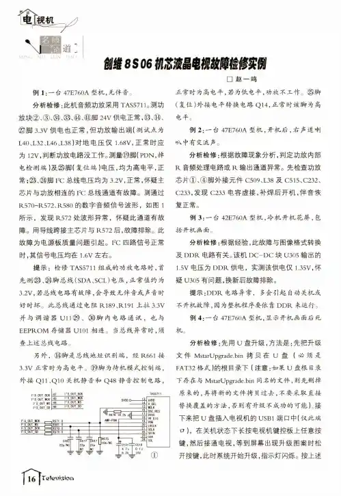
_s o e m液晶电鼸隨修实倒□赵一鸣例1:一台47E760A型机,无伴音。
分析检修:此机音频功放采用TAS5711。
测功 放块②、③、⑭、⑬、⑭、⑪脚24V供电正常,⑬、⑭、©脚 3.3V供电也正常,但功放输出端(测试点为 140丄32丄46丄38)对地电压仅1.68¥,正常时应 为12V,判断功放电路没工作。
测量⑲脚(P DN,掉 电检测端)及㉕脚(复位端)电压,均为高电平,正 常;⑳、⑭脚I2C总线电压均为3.2V,正常,怀疑主 芯片与功放相连的I2C总线通道有故障。
测通过 R570~R572、R580的数字音频信号波形,如图1所示,发现R572处波形异常,怀疑此通道有故 障。
用导线跨接主芯片与R572后,故障排除。
此 故障为电源板质量问题引起。
I2C四路信号正常 时,其信号电压均在1.6V左右。
提示:检修TAS5711组成的功放电路时,首 先测⑬、⑭脚总线(SDA、SCL)电压,正常值约为 3.2V,若总线电路有故障,会导致无伴音或声音时 好时坏。
此总线通过电阻R189、R191上拉3.3V 并与调谐器U11㉙、®脚内电路通讯,也与 E E P R O M存储器U101相连。
当总线异常时,须查上述总线电路。
另外,⑭脚是总线地址识别端,经R661接 3.3V正常时为高电平。
⑲脚为待机模式控制端,外接Q11、Q10关机静音和Q48静音控制电路,正常时为高电平,若为低电平,功放不工作。
@脚(复位)外接电平转换电路Q14,正常时该脚为高 电平。
例2: —台47E760A型机,开机后,右声道喇 »八中有交流声。
分析检修:根据故障现象分析,判定功放内部 R音频处理电路或R输出通道异常。
先检查功放芯片①、④脚外接元件C509、L38及C515、C232、C233,发现C233电容虚接,补焊后开机,伴音恢 复正常。
例3:—台42E760A型机,冷机开机花屏,包括开机画面分析检修:根据经验,此故障与图像格式转换及D D R电路有关。
Products Solutions Services操作手册iTEMP TMT72温度变送器BA01854T/28/ZH/04.20715255132020-10-20自下列版本起生效01.01(版本号)iTEMP TMT72目录Endress+Hauser 3目录1文档信息 (4)1.1文档功能 (4)1.2安全指南(XA) (4)1.3信息图标 (4)1.4工具图标 (5)1.5文档资料代号 (6)1.6注册商标 (6)2基本安全指南 (7)2.1人员要求 (7)2.2预定用途 (7)2.3操作安全 (7)3到货验收和产品标识 (8)3.1到货验收 (8)3.2产品标识 (8)3.3供货清单 (9)3.4证书和认证 (10)3.5运输和储存 (10)4安装 (11)4.1安装条件 (11)4.2安装 (11)4.3安装后检查 (16)5电气连接 (17)5.1接线 (17)5.2快速接线指南 (18)5.3连接传感器电缆 (18)5.4连接变送器 (19)5.5特殊接线指南 (20)5.6连接后检查 (21)6操作方式 (22)6.1操作方式概览 (22)6.2操作菜单的结构和功能 (25)6.3通过调试软件访问操作菜单 (27)6.4通过SmartBlue App 访问操作菜单 (29)7系统集成 (31)7.1设备描述文件概述 (31)7.2HART 通信的测量变量 (31)7.3支持的HART ®命令 (31)8调试 (34)8.1安装后检查 (34)8.2打开变送器 (34)8.3设置测量设备 (34)8.4写保护设置,防止未经授权的访问 (36)9诊断和故障排除...................379.1常规故障排除........................379.2现场显示单元上的诊断信息..............399.3通过通信接口查看诊断信息..............399.4诊断信息列表........................399.5事件日志............................409.6诊断事件概览........................409.7固件变更历史........................4110维护..............................4211维修..............................4211.1概述...............................4211.2备件...............................4211.3返厂...............................4211.4废弃...............................4212附件..............................4212.1设备专用附件........................4312.2通信专用附件........................4312.3服务专用附件........................4312.4系统组件............................4413技术参数..........................4513.1输入...............................4513.2输出...............................4613.3电源...............................4713.4性能参数............................4813.5环境条件............................5513.6机械结构............................5613.7证书和认证..........................5913.8补充文档资料........................6114操作菜单和菜单参数说明...........6214.1Diagnostics:诊断菜单.................6614.2Application:应用菜单.................7214.3System:系统菜单....................82索引.. (97)文档信息iTEMP TMT724Endress+Hauser1 文档信息1.1 文档功能文档中包含仪表生命周期各个阶段内所需的所有信息:从产品标识、到货验收和储存,至安装、电气连接、操作和调试,以及故障排除、维护和废弃。

Naída CI声音处理器用户指南简体中文用户指南适用于 Naída CI Q30 声音处理器2 Naída CI Q30 声音处理器用户指南标签标签符号及其意义:欧洲共同体合格标志。
于 2015 年授权粘贴 CE 标志型号生产日期序列号制造商防护类型:B存储温度范围为 20˚C (-4˚F) 至 +55˚C (131˚F)易碎请保持干燥请参见使用说明适合的大气压力范围为 70 kPa 到 106 kPa 之间,相当于海平线以上 3,000 m 到海平线以下 380 m 之间适合在相对湿度为 0-95% 的环境下使用按照国家和当地的适用法规进行处置IP57Naída CI Q30 的防护等级为 IP57。
该等级表示 Naída CI Q30 可防护下列状况:防尘,一次浸入 1m 深的水中 30 分钟,在 Dry & Store 干燥盒内干燥一整夜后出现故障翻新**仅在发货标签上标有‘翻新’时适用警告和警示警告• 窒息危险– 包含可造成吸入危险的小零件。
• 如果用户装有心脏起搏器,请勿使用 ComPilot ,因为这样可能会产生干扰。
请联系保健医生了解更多信息。
• 确保对佩戴 Naída CI Q30 声音处理器和配件的儿童予以相应监督。
• 由于可能产生窒息危险,请将电池和配件置于儿童无法触及的位置。
• 如果不慎吞入了任何零件,请立即就医。
• 不要在小孩无人照看的情况下在其周围放置电池或让其玩弄电池。
• 不要将电池放入嘴中。
• 不要咬或吞咽电池。
如果发生这种情况,请立即就医。
• 不要在无人照看的情况下让小孩玩弄或使用干燥系统。
• 将声音处理器和配件用于其预期用途之外的其他用途(例如,将其放入嘴中或咀嚼)可能会造成人身伤害。
• 不可对一次性电池充电。
• 不要让泄露的电池液接触皮肤、口或眼睛。
• 不要让电池靠近热源(例如存储于阳光直射处或温度很高的车内)。
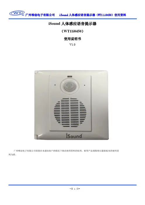
iSound人体感应语音提示器(WT11i0450)使用说明书V1.0广州唯创电子有限公司保留在未通知客户的情况下修改使用资料的权利。
新型产品规格将以最新版本的使用资料为准。
一、产品特点支持8~320Kbps MP3音频格式播放,音质优美;语音更新方便,用户可通过U盘将音频文件拷贝到内部FLASH;支持外挂最大64M SPI Flash 作为存储语音的载体;90度~120度扇面,4米人体感应距离;宽电压范围AC 100~250V继电器闭合由光感和人体感应共同控制,继电器干触点可接600W阻性负载继电器延时断开时间可通过iSound.mp3文件设置(10S~2540S)性能稳定,可外接有源音箱(外部功放)二、产品应用本产品并不是一个简单的语音提示器,而是一个具有智能人体感应,并带电源控制功能的智能人体感应语音提示器。
不仅带有语音提示功能,还具有电源控制功能,在播放语音提示语的同时还可以控制设备电源的打开和关闭,设备电源的打开由光感应和人体感应共同控制,即当光亮度低于学习的光亮度而且有人体感应时,继电器闭合(设备电源打开)。
采用人体感应触发方式,具有感应角度大、触发灵敏等特点。
智能触发,无需手动操作。
适合用于楼梯灯、通道灯光控制、迎宾门等场合。
三、产品规格工作电压:AC 100~250V/50~60Hz待机电流:≤3.5mA播放语音功耗:≤1W负载:≤600W(阻性负载)FLASH容量:标配16Mbit FLASH(可定制4~64Mbit)人体感应角度:90~120度人体感应距离:4米内使用环境:仅限于室内使用,相对湿度小于95%产品入墙部分尺寸:86mm*86mm*28mm产品墙外部分尺寸:86mm*86mm*15mm四、 功能面板注1: USB 接口可以连接U 盘,从U 盘拷贝语音到内部FLASH ,不能直接连接电脑下载语音。
注2:该版本暂不支持TF 卡。
五、 FLASH 容量与语音长度关系该版本支持8~320Kbps 码率的MP3音频文件,语音的时间长度和码率有关。


DT-3型电压监测仪说明书目录一、产品简介 (1)二、产品型号说明及主要技术参数 (1)三、产品原理图 (2)四、产品数据采集 (2)1.GPRS无线通讯模块采集 (2)2.GSM短信采集 (2)3.RS485通讯采集 (2)五、通信管理系统 (3)六、监测终端设备功能 (4)七、产品按键说明 (6)八、产品安装 (6)九、产品外形尺寸图 (8)不会由于人为的误操作给您或您的单位带来不必要的损失。
如果您认为说明书中所述内容有任何不清楚或不妥之处,请您与我公司技术服务部取得联系,我们将竭诚为您服务。
如由于用户违规操作或以非正常方式使用本产品所造成的损失,本公司将不承担责任。
在此,感谢您选用斯麦尔公司的产品。
DT3型100V/220V/380V电压监测仪根据DL/T 500-2009《电压监测仪订货技术条件》研发设计,是供电和用电部门、企业监测与统计工频电压有效值的智能仪表。
它除具有“时钟”、“电压表”功能外,还可显示、存储、统计电压超高、超低、合格时间,最高、最低电压及其出现时间,电压合格率等十几项电压质量统计数据,并且设备具备无线GPRS或GSM短信两种数据采集方式。
是供电部门达到《国家电网公司农村电网电压质四、产品数据采集设备提供三种数据采集方式,GPRS公网、GSM短信及RS485串口。
GPRS公网、GSM 短信均属于无线通讯,无线通信模块采用同一种型号,通信模块具备工业级标准,三种方式有各自的优点。
1.GPRS无线通讯模块采集GPRS方式利用移动的GPRS网络传输采集数据通信可靠、迅速。
此方式需要用户具备固定的IP地址,能够访问互联网。
GPRS传输特点:➢上电后自动拨号,寻固定IP地址➢掉线自动连接➢传输速率范围广(30Kbps~115Kbps)➢GPRS按数据流量计费➢数据传输速度快、数据量大2.GSM短信采集短信采集需要主站端配备GSM短信接收器。
GSM传输特点:➢配置简单➢数据量小➢GSM短信按照移动或联通资费标准收取➢采集数据慢3.RS485通讯采集采用RS485通讯时,装置需要与后台的RS485通讯接口连接。
USB Adio3用户手册V150301USB Adio3概述USB Adio3是Adio产品的硬件第3次升级,底层程序第18次升级,上位机软件50个版本的基础上研发出来的一款信号采集神器。
依靠电脑USB供电,无需外部电源,2AI,2DI,2DO(可驱动3.3V继电器),2路5V/3.3V 输出。
可直接配合上百种传感器使用,9种自动保护措施,使用十分安全方便。
无需驱动,数据传输速率在1K左右,可在XP/WIN7等系统下稳定运行,有配套的电脑软件,包含波形显示、存储、分析等十余种功能,操作简单直观。
●100余种传感器的多功能采集卡,解决普通卡不通用的烦恼。
●9重安全保护,免驱设计,把卡搞坏也是件难事。
●5种电脑程序,解决不会编程的烦恼,安装完3分钟即会使用采集卡与软件。
●应用案例及软件会定期更新,为您的更多更好使用提供长期保障。
目录1、产品性能介绍 (4)1.1 性能指标 (4)1.2 特点 (4)1.3软件功能 (5)1.4 硬件描述 (5)1.5 主要应用领域 (6)2 应用软件(程序) (7)2.1全功能程序 (7)2.2 简易采集程序 (7)2.3采集与控制程序 (8)2.4高速采集程序 (8)2.5多卡同步采集程序 (9)3、快速入门 (10)3.1 硬件连接 (10)3.2 软件运行 (11)4、应用举例 (11)5、稳定性、质保及售后 (12)5.1 环境测试 (12)5.2 操作说明 (12)5.3 出货清单 (13)5.4质保及售后 (13)附录一:DLL函数说明 (14)附录二:VC++例程 (15)附录三:故障排除 (16)售后服务联系方式 ........................................................................................................... 错误!未定义书签。
文档权利及免责声明 (17)微信增值服务 ................................................................................................................... 错误!未定义书签。
YAV Z3定向声音传感器(交流输出)
技术手册V1801
武汉亚为电子科技有限公司
0.产品概述
YAV Z3定向声音传感器具有声级计的全部功能,克服了传统手持式声级计信号输出复杂、感应不远的缺点,可采集声音波形信号。
十分方便的与PLC、PC、DCS等控制设备兼容而组成的精细噪声测量系统,特别适合集成于各种环境、产品监控设备,组成单点或多点噪声监控网络,是各类噪声源的噪声监控、检测、监测、实验的理想选择。
尤其是与YAV RJ45 8AD HS采集卡结合,可定向采集声音波形、分析设备声音频率,乃至达到故障诊断的效果。
技术指标
输入输出功能指标
硬件特点
●能直接输出线性模拟量,AD采集更加方便解决了很多客户直接采集波形的痛苦,也可以直接作为
分贝传感器使用。
●可还原声音波形信号(采样率44.2khz,AD精度大于等于16位)
●电压与噪音成线性关系,具体可以根据噪音计校准。
●灵敏度高,店主亲测,在封闭环境中,正常说话10米内可以检测到。
●供电电压范围宽,本次设计的模块,电源范围可从5-15V。
1.传感器的安装及固定
●室内外安装
●简易万能固定夹
●定点噪声测试架
●需做防风防雨处理
2.测试方向
测试探头正前方110°内的近距离信号,其他方向或远处的声音,可以自动滤除。
相比之下,Z2一般用于测试远距离的声音,测试环境音。
Z3用于测试特定设备声音规律。
尤其是与YAV RJ45 8AD HS采集卡结合,可定向采集声音波形、分析设备声音频率,乃至达到故障诊断的效果。
如上图所示,YA V Z3属于单一指向型传感器。
可以隔离其他方向的噪音。
YA V Z2属于无指向性传感器。