安全阀计算手册样本
- 格式:doc
- 大小:229.50 KB
- 文档页数:18
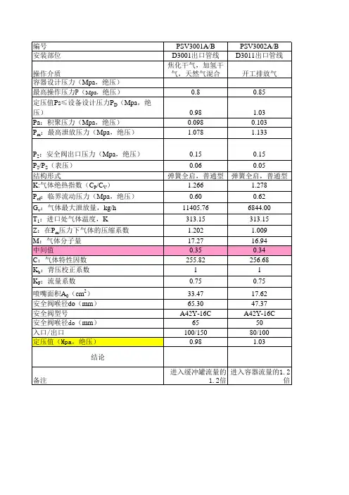
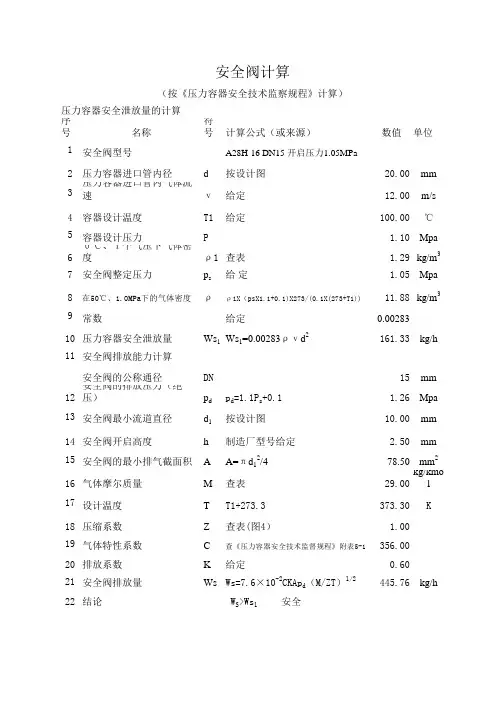
序号名称符号计算公式(或来源)数值单位1安全阀型号A28H-16 DN15 开启压力1.05MPa 2压力容器进口管内径d 按设计图
20.00mm 3压力容器进口管内气体流速ν给定
12.00m/s 4容器设计温度T1给定
100.00℃5容器设计压力P
1.10Mpa 60℃、1个气压下气体密度ρ1查表
1.29kg/m 37安全阀整定压力p s 给 定
1.05Mpa 8在50℃、1.0MPa下的气体密度ρρ1X(psX1.1+0.1)X273/(0.1X(273+T1))11.88kg/m 39常数给定
0.0028310压力容器安全泄放量Ws 1Ws 1=0.00283ρνd 2161.33kg/h 11安全阀的公称通径DN
15mm 12安全阀的排放压力(绝压)p d p d =1.1P s +0.1 1.26Mpa 13安全阀最小流道直径d 1按设计图
10.00mm 14安全阀开启高度h 制造厂型号给定 2.50mm 15安全阀的最小排气截面积A A=πd 12/4
78.50mm 216气体摩尔质量M 查表
29.00kg/kmol 17设计温度T T1+273.3
373.30K 18压缩系数Z 查表(图4)
1.0019气体特性系数C 查《压力容器安全技术监督规程》附表5-1356.0020排放系数K 给定
0.6021安全阀排放量Ws Ws=7.6×10⁻²CKAp d (M/ZT)
1/2
445.76kg/h 22结论 W S >Ws 1 安全安全阀计算
(按《压力容器安全技术监察规程》计算)
压力容器安全泄放量的计算
安全阀排放能力计算。
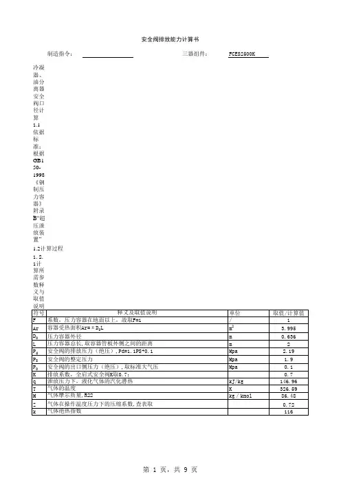
安全阀排放能力计算书
制造指令:三器组件:FCES2500K
1.0冷凝器、油分离器安全阀口径计算
1.1依据标准:根据GB150-1998《钢制压力容器》附录B“超压泄放装置”
1.2计算过程
s1
对于制冷剂采用R22,其P0/P d=0.0457
大于(2/(k+1))k/(k-1)=0.0165
50.82
s2
油分离器安全泄放量(W s2)的计算
对于制冷剂采用R22,其P0/P d=0.0456621大于(2/(k+1))k/(k-1)=0.016499757
50.82
根据GB150-1998《钢制压力容器》附录B“超压泄放装置”B4.3条之b)款规定,油分离器与
冷凝器之间用足够大的管道连接,且之间无截止阀,故可以看作一个容器,故两器的
1冷凝器与油分离器系统安装两个相同的安全阀,在这种情况下单个安全阀的泄放量是总泄放由设计可看出,冷凝器与油分离器的容器系统安装两个相同安全阀的情况下,
单个安全阀最小流道直径(阀座喉径)应不小于10.5mm
2.0蒸发器安全阀口径计算
2.1依据标准:根据GB150-1998
《钢制压力容器》附录B“超压泄放装置”
2.2计算过程
s 0.82
由设计可看出,蒸发器只安装一个安全阀的情况下,安全阀最小流道直径应不小于
9mm
编制:校核:审核:。
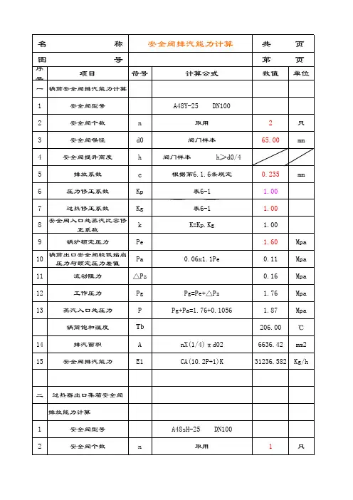
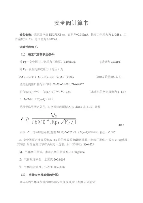
安全阀计算书设备参数:蒸汽分汽缸DN273X8㎜,容积V=0.085m3,最高工作压力为1.4MPa,工作温度为105,进口管为φ108X6 。
计算过程如下:(1).确定气体的状态条件:设Po—安全阀出口侧压力(绝压)0.103MPa (近似为0.1MPa)则P d—安全阀泄放压力(绝压)为P d=1.1Ps+0.1 =1.1×1.1Pw+0.1=1.794MPa (GB150附录B4.2.1)当安全阀出口侧为大气时: Po/Pd=0.103/1.794=0.057而{2/(k+1)}k/(k-1)={2/(1.4+1)}1.4/(1.4-1)=0.55 (水蒸汽的绝热指数为k=1.3)∴Po/Pd<(2/(k+1))k/(k-1)是属于临界状态条件, 安全阀排放面积A按GB150式(B5)计算(B5)式中: C:气体特性系数,查表B1或C=520√k(2/(k+1)(k+1)/(k-1))得出:C=347K:安全阀额定泄放系数,K=0.9倍的泄放系数(泄放系数由制造厂提供,一般为0.75);或按《容规》附件五第二节有关规定中选取. 本计算书取:K=0.675M:气体摩尔质量,水蒸汽摩尔质量M=18.2Kg/kmolZ:气体压缩系数,水蒸汽Z=0.9216T:气体绝对温度,T=273+105=378k(2). 容器安全泄放量的计算:盛装压缩气体或水蒸汽的容器安全泄放量,按下列规定来确定a.对压缩机贮罐或水蒸汽的容器,分别取压缩机和水蒸汽发生器的最大产气量;b.气体储罐等的安全泄放量按GB150式(B1)计算Ws=2.83×10⁻³ρυd2㎏/h (B1)ρ:为排放压力下的气体密度㎏/m3.ρ=M/Vρ=M(分子量)×Pw’(排放绝对压力)×T标/P (V×T)空气分子量 M=18.2 标准状态理想气体摩尔体积 V=22.4排放绝对压力 Pw’=17.94㎏/㎝2大气绝对压力 P=1.03㎏/㎝2将M、Pw’、 T标、P、V、T代入上式得ρ=18.2×17.94×273/1.03×22.4×378=10.22㎏/m3υ:容器在工作压力下的进口管的气体流速m/s;根据HG/T20570.6-95中表2.0.1饱和水蒸汽管径DN :200~100mm时,υ:35~25m/s 所以本计算书取:υ=25m/sd:进气管内径, d=92mm将上述ρ、ν、d代入式(B1)得Ws=2.83×10-3×10.22×25×922 =6120㎏/h(3). 安全阀排放面积的计算:将上述Ws、C、K、P d、M、Z、T代入上式(B5)可计算出:A=873.3mm2根据设备工况选用全启式安全阀则:A=0.785d02=873.3mm2安全阀喉径为:d0=33.4㎜根据安全阀公称直径与喉径对照表表1 安全阀公称直径与喉径对照表∴选用公称直径DN80的全启式安全阀.。

安全阀选型计算书编写:张景富西安协力动力科技有限公司二零一零年九月一、加热器安全阀的选型计算1.主要计算参数:该电厂共有四台热网加热器,每台加热器的壳程有2个蒸汽进口(Ф720×24),管程进出口为Ф720×10,疏水管Ф273×7,加热蒸汽总流量250~300t/h,蒸汽压力0.4Mpa,壳程工作温度227℃,换热管Ф19×2,加热器管程水进口压力为1.6Mpa,进出口水温70~130℃。
2.壳程安全阀的选型根据GB150-1998附录B5“容器安全泄放量的计算”热网加热器壳程的水蒸汽的容器安全泄放量为:W S=2.83×10⁻³ρvd2式中 W S----容器的安全泄放量,kg/h;ρ----泄放压力下气体密度,kg/m3。
v----容器进料口内的流速,m/s;d----容器进料口的内径,mm;加热器壳程蒸汽压力为0.4Mpa,即工作压力为0.3Mpa,在这程压力下蒸汽密度ρ=1.66kg/ m3按四台设备共8个进口,每个进口蒸汽流量QQ=300÷8=37.5t/h=10.42kg/sQ/ρ=10.42/1.66=6.277 m3/s进口管截面:A=π0.72/4=0.385㎡进料管内的流速:V=6.277/0.385=16.3m/sW S=2.83×10-3×1.66×16.3×7002=37521 kg/h按锅炉压力容器压力管道安全泄放装置实用手册《安全阀》一书中的附录一全启式安全阀额定排量(kg/h),附表1-2可以查出开启压力为0.7Mpa,排放量为38700 kg/h,阀座喉径125mm合适,(注意:壳程设计压力为0.8Mpa)按青岛电站阀门厂产品选择公称直径DN200安全阀,型号:A48Y-16C DN200 3.管程安全阀的选择:按《安全阀》一书第183页换热器管破裂时的泄放量计算:W=5.6×d2×(G1×ΔP)1/2式中 W----安全泄放量,kg/h ;d----换热管的内径,mm ;G 1----液相密度,kg/m 3;ΔP---管程与壳程的压差,MPa 。
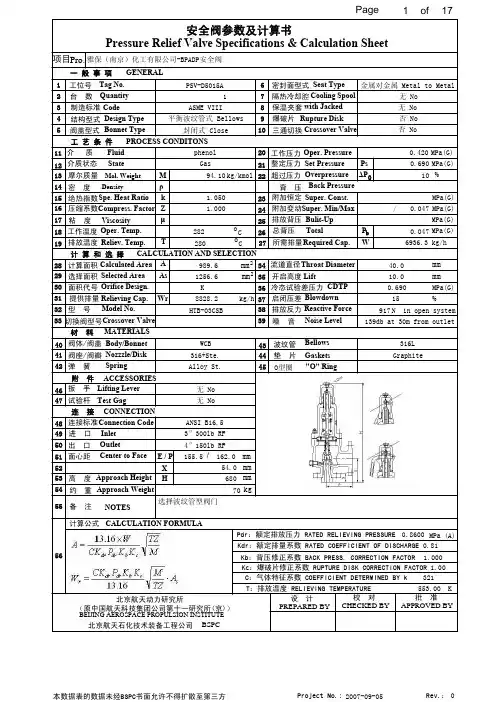
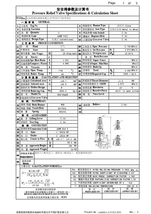
1234511121314151617181920212223242526272829303132333435363738工位号台 数结构型式阀盖型式波纹管试验杆扳 手制造标准所需排量工作压力整定压力工作温度排放温度背 压超过压力压缩系数绝热指数启闭压差计算面积流道直径高 度W M Ps Zk As A Wr 特殊技术要求批 准校 对设 计kg/h MPa(G)oC%mm 2mmΔP 0PREPARED BY CHECKED BY APPROVED BY 工 艺 条 件一 般 事 项GENERALTag No.Quantity Design TypeBonnet Type BellowsTest GagLifting Lever PROCESS CONDITONS CodeRequired Cap.Oper. Pressure Set Pressure Oper. Temp.Reliev. Temp.Back Pressure Overpressure Compress. Factor Spe. Heat RatioBlowdown Calculated Area Throat DiameterApproach Height P b 39粘 度μViscosity(原中国航天科技集团公司第十一研究所(京))北京航天动力研究所678910密封面型式Seat Type 金属对金属 Metal to Metal保温夹套with Jacked 爆破片Rupture Disk 三通切换Crossover Valve介 质Fluid 摩尔质量Mol. Weight密 度Density Super. Const.附加恒定介质状态StateSuper. Min/Max 附加变动Built-Up排放背压Total总背压计 算 和 选 择CALCULATION AND SELECTION 选择面积Selected Area 面积代号Orifice Design.提供排量Relieving Cap.型 号Model No.切换阀型号冷态试验差压力CDTP ρ排放反力Reactive Force噪 音Noise Level 材 料MATERIALS连 接CONNECTION 404142阀体/阀盖Body/Bonnet 434445阀座/阀瓣Nozzle/Disk弹 簧Spring o C mm 2484950连接标准Connection Code 进 口Inlet 出 口Outlet附 件ACCESSORIES4647面心距Center to FaceE / P X 约 重Approach Weight H 51525354 2ASME VIII常规式 Conventional封闭式 Close无 No否 No 否 NoT 空气Gas 29.00kg/kmol 1.0010.9954-6060 2.700MPa(G) 2.97010.00MPa(G)MPa(G)/MPa(G)MPa(G) 0.000 2330.4kg/h 116.4 153.9E 3082.0HTO-03aCB14.0MPa(G)2.97010264N in open systemWCB 304+Ste.50CrVA 无(No)无 No 无 No ASME B16.5105.039.0 450 201″300lb RF 2″150lb RFmmmmmm kgC:气体特征系数 COEFFICIENT DETERMINED BY kPdr:额定排放压力 RATED RELIEVING PRESSURE Kb:背压修正系数 BACK PRESS. CORRECTION FACTOR T:排放温度 RELIEVING TEMPERATUREMPa (A)K Kdr:额定排量系数 RATED COEFFICIENT OF DISCHARGE 5557计算公式CALCULATION FORMULA3.36800.8373161.000Kc:爆破片修正系数 RUPTURE DISK CORRECTION FACTOR 1.00333.00Crossover Valve /115.0安装位置Location %提供入口配对法兰。
2.0寸卫生级全启式安全计算书根据《实用阀门设计手册》(陆培文主编,机械工业出版社出版,2006年1月第1版)所列安全阀的通用计算项目如下(表5-39)及安全阀专用计算项目:通用及专用计算项目:1.阀体厚度计算2.阀盖厚度3.阀座密封面面上计算比压4.弹簧理论计算5.安全流道直径计算6.安全阀额定排量计算本阀门阀体材质采用316L,阀盖采用304,快装卡箍采用304,因阀门设计手册上没有相应的材质,故采用相近的1Cr18Ni9Ti材质进行验算。
一.阀体厚度计算(表5-168,第1014页)阀体厚度S’B=(P*Dn)/(2.3*[σL]-P)+C;其中:P为公称压力,安全阀设计公称压力:0.7Mpa,故P=0.7计算通径Dn=72.9mm许用应力[σL]查表3-3(第597),[σL]=92Mpa设计给定腐蚀余量C为0.5mm计算给果:S’B=0.846mm阀体最薄处设计厚度S B:1.65mmS’B< S B=1.65mm故阀体厚度设计合理。
二.阀盖厚度因本安全阀采用的是卡箍连接,其阀盖等同于快装盲板,依据DIN 32675-2009标准,对于快装接头使用工作压力之规定:Rohraußendurchmesser von 6,35 mm bis 42,4 mm: 2,5 MPa (25 bar);Rohraußendurchmesser von 48,3 mm bis 76,2 mm: 1,6 MPa (16 bar);Rohraußendurchmesser von 85,0 mm bis 219,1 mm: 1,0 MPa (10 bar).本安全阀连接采用85口径的快装卡盘(106),依据以上所引用标准要求,工作压力为1.0Mpa,故符合设计要求。
三.3.阀座密封面面上计算比压(表5-197,第1115页)介质压力为p时密封面上比压力:q1=D m(p S-p)/4b≥q MF因设计输入的整定压力p s=0.7Mpa,依据安全阀密封性能试验的相关规定《实用阀门设计手册》表10-40,安全阀的密封性能试验压力,为整定压力的90%,故:设备正常工作压力:p=0.63Mpa,关闭件密封面平均直径:DM=32.16mm(设计给定)关闭件密封面宽度:b=1.3mm (设计给定)M密封面必需压力: q MF=(0.4+0.6PN)/ 10/b(表3-13,662页)Mb=1.3mm(设计给定)MPN:取1.0Mpa计算结果:q=2.77MpaMF密封面比压力:q1= D m(p S-p)/4b =4.33 Mpa,验算结果:q1=4.33≥q MF =2.77, 故密封设计合格。
DESCRIPTIONThis document briefly describes the one phase relief valve calculation spreadsheet, which will be the standard relief valve calculation tool of LGN. The calculation method used in this spreadsheet isbased on calculation methods as given in API 520 part 1 (7thed., 2000, page 41-56). It is strongly recommended to read these pages before one starts with the calculations. All calculations are done in SI units.FORMULASGAS AND VAPOR FLOW∙ Flow through the relief valve is called critical if112-⎪⎪⎭⎫⎝⎛+≤i ik k i bk P Pwhere:P b Maximum back pressurekPa a PUpstream relieving pressure. This is the set pressure plus the allowable overpressure plus atmospheric pressure.kPa a k i Ideal gas heat capacity ratio or C p,ig / C v,ig -C p,ig Ideal gas heat capacity at constant pressure kJ/kg.K C v,igIdeal gas heat capacity at constant volumekJ/kg.KAlthough this equation is only valid for ideal gases, it may be used to calculate critical pressure ratio. k i can be obtained from table 7 in API 520 part 1. Otherwise, the following formula can be used:RMW c MW c k ig p ig p i -⋅⋅=,,where:k i Ideal gas heat capacity ratio-C p,ig Ideal gas heat capacity at constant pressure kJ/kg.K MW Molecular weight -R Gas constant KJ/kmol.KIf the ideal gas heat capacity is not known, use the actual heat capacity in the same equation. Errors are found to be only small.∙ Critical Flow (Gas or Vapor): The following equation can be used to size a pressure relief device in gas or vapor service that operates at critical flow conditions.MWZT KKP KC W A cbd⋅⋅⋅⋅⋅⋅=160,13where:A Required discharge area (for standard types see table 1) mm 2W Required mass flow through the device. kg/hr CCoefficient determined from an expression of the ratio ofthe specific heats (k = C p /C v ) of the gas or vapor at inlet relieving conditions. This can be obtained from figure 32 in API 520 or with the following formulae:1112520-+⎪⎭⎫ ⎝⎛+⋅⋅=k k k k C hr lb Rlb lb f mole m ⋅⋅⋅ C p Heat capacity at constant pressure at relieving conditionskJ/kg.K C vHeat capacity at constant volume at relieving conditions kJ/kg.K K dEffective coefficient of discharge. For preliminary sizing, use the following values:∙ For relief valve with or without rupture disk: 0.975 ∙ For installation of rupture disk only: 0.62-P Upstream relieving pressure. This is the set pressure plus the allowable overpressure plus atmospheric pressure.kPa a K bCapacity correction factor due to back pressure, to be applied for balanced type relief valves only; Forpreliminary sizing, this can be estimated from figure 30 in API 520 (see also table 2).For conventional and piloted operated valves K b =1 -K cCombination correction factor for installations with a rupture disk upstream of the PSV.∙ K c = 1.0 when a rupture disk is not installed∙ K c = 0.9 when a rupture disk is installed upstreamthe PSV and does not have a published value -T Relieving temperature at inlet of the relief valve. K Z Compressibility factor at inlet relieving conditions -MWMolecular weightKg/kmolThe above equation should also to be used to size balanced pressure relief valves in subcritical flow (in this case K b should be obtained from the manufacturer).∙ Subcritical Flow: Required relief valve area for conventional and pilot operated relief valves()bcdP P P MW TZ KKF W A -⋅⋅⋅⋅⋅⋅=29.17where:A Required discharge area (for standard types see table 1) mm 2W Required mass flow through the device. kg/hr F 2Coefficient of subcritical flow, see figure 34 in API 520 or use the following equation:()()⎥⎥⎥⎦⎤⎢⎢⎢⎣⎡--⋅⋅⎪⎭⎫ ⎝⎛-=-r r r k k F kk k 111122- kRatio of specific heats, C p / C v- r Ratio of back pressure to upstream relieving pressure, P b / P- C p Heat capacity at constantkJ/kg.K C v Heat capacity at constant volumekJ/kg.K KdEffective coefficient of discharge. For preliminary sizing, use the following values:∙ For relief valve with or without rupture: 0.975 ∙ For installation of rupture disk only: 0.62-K cCombination correction factor for installations with a rupture disk upstream of the PSV.∙ K c = 1.0 when a rupture disk is not installed∙ K c = 0.9 when a rupture disk is installed upstreamthe PSV and does not have a published value -Z Compressibility factor at inlet relieving conditions - T Relieving temperature at inlet of the relief valve KMW Molecular weightKg/kmol P Upstream relieving pressure. This is the set pressure plus the allowable overpressure plus atmospheric pressure.kPa a P bMaximum back pressurekPa aSTEAM RELIEFSHNcbdKKKKKP WA ⋅⋅⋅⋅⋅⋅=4.190where:A Required discharge area (for standard types see table 1) mm 2W Required mass flow through the device.kg/hr PUpstream relieving pressure. This is the set pressure plus the allowable overpressure plus atmospheric pressure.kPa a K dEffective coefficient of discharge. For preliminary sizing, use the following values:∙ For relief valve with or without rupture: 0.975 ∙ For installation of rupture disk only: 0.62-K bCapacity correction factor due to back pressure. This can be obtained from the manufacturer’s literature or estimated from figure 30 of API 520 (see also table 2). The back pressure correction factor applies to balanced bellows valves only.For conventional and piloted operated valves K b =1 -K cCombination correction factor for installations with a rupture disk upstream of the PSV.∙ K c = 1.0 when a rupture disk is not installed∙ K c = 0.9 when a rupture disk is installed upstreamthe PSV and does not have a published value -K NCorrection factor for Napier equation.For P ≤ 10,339 kPaaK N = 1For P > 10,339 and P ≤ 22,057 kPaa106103324.010*******.0-⋅-⋅=P P KN-K SHSuperheat steam correction factor. This can be obtained from table 3 (equivalent to table 9 of API 520). For saturated steam at any pressure K SH = 1.0-LIQUID RELIEFblvcwdP P G KKKKQ A -⋅⋅⋅⋅=78.11where:A Required discharge area (for standard types see table 1) mm2Q Volume flow rateL/min K dEffective coefficient of discharge that should be obtained from the valve manufacturer. For a preliminary sizing, an effective discharge coefficient can be used as follows: ∙ For relief valve with or without rupture disk in liquidservice: 0.65∙ For installation of rupture disk only: 0.62-K W Correction factor due to back pressure. If the back pressure is atmospheric, use a value for K w of 1.0. Balanced bellows valves in back pressure servicerequire the correction factor to be determined from table 2 (equivalent to figure 31 of API 520). Conventional and pilot operated valves require no special correction. -K cCombination correction factor for installations with a rupture disk upstream of the PSV.∙ K c = 1.0 when a rupture disk is not installed∙ K c = 0.9 when a rupture disk is installed upstreamthe PSV and does not have a published value -G l Liquid gravity at flowing conditions referred to water at standard conditions- P Upstream relieving pressure. This is the set pressure plus the allowable overpressure plus atmospheric pressure.kPa a P b Maximum back pressurekPa a K VCorrection factor due to viscosity. Factor can be determined from figure 36 in API 520 or from the following equation:.15.175.342878.29935.0-⎪⎭⎫ ⎝⎛++=Rn Rn K v-Rn Reynolds number.AG Q Rn l ⋅⋅⋅=μ18800-μLiquid viscositycPTo make an estimate for the area, initially K v = 1 is taken and an initial area can be calculated. From there the Reynolds number can be calculated. With this Reynolds number K v can be calculated and from there the correct estimate for the relief valve area.RUPTURE DISK SIZING ONLYThe sizing of a rupture disk is done by using the appropriate equation as listed above. When using these equations, a coefficient of discharge, K d of 0.62, should be used.VALVE SELECTIONWhen the required size has been calculated, the valve is selected based on API 526 (see table 1). The valve types are standard types. For high-pressure systems a different valve number from the ones given may be required. This must be checked by the user.If the required area is greater than that of a 8 T 10 size multiple valves will be specified. All data concerning selected area and maximum flow through selected relief valve will then be based on one valve.TEMPERATURE ESTIMATESThe spreadsheet estimates a device outlet temperature under chapter “Device Output Data”.The outlet temperature of the valve in steam service has been estimated by100100⋅=b sat P Twhere:P b Back pressurekPa a T satSteam saturation temperature°CAbove pressures of 1 bar this is accurate to about 2 %.The outlet temperature for vapors and gasses, under the assumption of adiabatic expansion, is determined by:kk b inout P P T T 1-⎪⎭⎫ ⎝⎛⋅=where:T out Relieving temperature at outlet of the relief valve K T in Relieving temperature at inlet of the relief valve K P b Maximum back pressurekPa a P Upstream relieving pressure. This is the set pressure plus the allowable overpressure plus atmospheric pressure.kPa a kRatio of specific heats at relieving conditions, C p / C v-TABLESTable 1Orifice Areas and TypesTable 2Gauge Pressure Ratio in %Correction Factors, K b and K wTable is based on figures 30 and 31 in API 520 PT 1 (p. 37+38)Where:P b Back Pressure kPa g P s Relief device set pressure KPa gTable 3Superheat Correction Factors, KSH (=Table 9 in API 520(p. 51))HISTORYChanges from V 1.0 to V 1.1∙Added the legal statement∙J17: conversion factor 2.20462 in stead of 2.2046∙J18/19: corrected formulas and gave correct values for 1 atm in kPa and psi.∙J21: conversion factor 4.1868 in stead of 4.186.∙J23: corrected conversion error (factor 1000) for lb/ft3.∙J25/26: Removed saturated steam temperature and superheat temperature.∙F27: removed specific gravity from input, as density is already an input.∙F31 (new): Corrected formula to be used for gas or steam and lookup to start at zero value∙F34 (new): lookup to start at zero value.∙J35 (new): rounded the temperature off to full decades.∙Removed Cv value of valve.∙Added note that if multiple valves are specified, the data is per valve.∙On sheet values:∙Removed orifice Cv value∙Corrected conversion from psig to kPaa (superheat correction factors-table) and corrected one value∙Rounded off the gauge pressure ratio and corrected it for value used (not bar).∙Changed Pb/P for Kw in that table to start at 0, not 1.∙Removed the factor 100 used for critical flow area calculation∙Changed text part of area and flow calculation.∙Changed pressure to work in kPa, not bar, for X49.∙Put specific gravity on this sheet for use in formulas.∙Added references to Word-file∙Added valve selection and temperature estimates paragraphs∙Added symbols∙Changed order of tables and corrected∙in table 1 the area of an H orifice is 0.785 in2, not 1.00 in2∙in table 2 set the bottom limit for Pb/P at 0, not 1.∙In table 3 800°F, 1500 psig K sh=0.86, not 0.85.∙In case k or ki is 1, value is changed to 1.+1.e-10∙In case of Liquid Relief with multiple relief valves, the actual valve area was calculated as zero.Corrected by calculating the number of relief valves correctly.Changes from V 1.1 to V 1.2∙Removed units of measurement for ki (Cell K23)∙Changed unit of measurements of Superimposed Backpressure from delta pressures to absolute pressures. The formula that calculates the Maximum Backpressure has been correctedaccordingly.Changes from V 1.2 to V 1.3∙Layout changes to the spreadsheet, manual and TQM registration.∙Modified Kb calculation that was based on Pb/Pset and is now based on the ratio Pb/Prel∙Added warning to the spreadsheet that in case RV = Rupture Disk, the user also must select Yes in box “Rupture Disk combined with RV”.∙Added warning that in case of subcritical balanced relief valves, the Kb factor has to be obtained from the manufacturer.∙Adjusted the formula that calculates factor Kn, required factor for steam relief valves.∙Modified the lookup that determined factor Ksh. Old method could give a wrong value.∙Adjusted the orifice size description in table 1.Changes from V 1.3 to V 1.4∙Modified calculation of liquid specific gravity∙Comments for back pressure, built-up back pressure and superimposed back pressure aligned with API。
DESCRIPTIONThis document briefly describes the one phase relief valve calculation spreadsheet, which will be the standard relief valve calculation tool of LGN. The calculation method used in this spreadsheet is based on calculation methods as given in API 520 part 1 (7th ed., , page 41-56). It is strongly recommended to read these pages before one starts with the calculations. All calculations are done in SI units.FORMULASGAS AND VAPOR FLOW• Flow through the relief valve is called critical if112-⎪⎪⎭⎫⎝⎛+≤i i k k i b k P Pwhere:P bMaximum back pressurekPa a P Upstream relieving pressure. This is the set pressure plus the allowable overpressure plus atmospheric pressure.kPa a k i Ideal gas heat capacity ratio or C p,ig / C v,ig -C p,ig Ideal gas heat capacity at constant pressure kJ/kg.K C v,ig Ideal gas heat capacity at constant volumekJ/kg.KAlthough this equation is only valid for ideal gases, it may be used to calculate critical pressure ratio. k i can be obtained from table 7 in API 520 part 1. Otherwise, the following formula can be used:RMW c MW c k ig p ig p i -⋅⋅=,,where:k iIdeal gas heat capacity ratio-C p,ig Ideal gas heat capacity at constant pressure kJ/kg.KMW Molecular weight -R Gas constant KJ/kmol.KIf the ideal gas heat capacity is not known, use the actual heat capacity in the same equation. Errors are found to be only small.•Critical Flow (Gas or Vapor): The following equation can be used to size a pressure relief device in gas or vapor service that operates at critical flow conditions.MWZT K K P K C W A cb d ⋅⋅⋅⋅⋅⋅=160,13where:A Required discharge area (for standard types see table 1) mm 2 W Required mass flow through the device. kg/hr CCoefficient determined from an expression of the ratio of the specific heats (k = C p /C v ) of the gas or vapor at inlet relieving conditions. This can be obtained from figure 32in API 520 or with the following formulae:1112520-+⎪⎭⎫⎝⎛+⋅⋅=k k k k Chr lb R lb lb f mole m ⋅⋅⋅C p Heat capacity at constant pressure at relieving conditionskJ/kg.K C vHeat capacity at constant volume at relieving conditions kJ/kg.K K dEffective coefficient of discharge. For preliminary sizing, use the following values:• For relief valve with or without rupture disk: 0.975 • For installation of rupture disk only: 0.62-P Upstream relieving pressure. This is the set pressure plus the allowable overpressure plus atmospheric pressure.kPa a K bCapacity correction factor due to back pressure, to be applied for balanced type relief valves only; Forpreliminary sizing, this can be estimated from figure 30 in API 520 (see also table 2).For conventional and piloted operated valves K b =1 -K cCombination correction factor for installations with a rupture disk upstream of the PSV.• K c = 1.0 when a rupture disk is not installed• K c = 0.9 when a rupture disk is installed upstreamthe PSV and does not have a published value -T Relieving temperature at inlet of the relief valve. K Z Compressibility factor at inlet relieving conditions -MWMolecular weightKg/kmolThe above equation should also to be used to size balanced pressure relief valves in subcritical flow (in this case K b should be obtained from the manufacturer).•Subcritical Flow: Required relief valve area for conventional and pilot operated relief valves()b c d P P P MW TZ K K F W A -⋅⋅⋅⋅⋅⋅=29.17where:A Required discharge area (for standard types see table 1) mm 2 W Required mass flow through the device. kg/hr F 2Coefficient of subcritical flow, see figure 34 in API 520 or use the following equation:()()⎥⎥⎥⎦⎤⎢⎢⎢⎣⎡--⋅⋅⎪⎭⎫ ⎝⎛-=-r r r k k F k k k111122- kRatio of specific heats, C p / C v- r Ratio of back pressure to upstream relieving pressure, P b / P- C p Heat capacity at constantkJ/kg.K C v Heat capacity at constant volumekJ/kg.K KdEffective coefficient of discharge. For preliminary sizing, use the following values:• For relief valve with or without rupture: 0.975 • For installation of rupture disk only: 0.62-K cCombination correction factor for installations with a rupture disk upstream of the PSV.• K c = 1.0 when a rupture disk is not installed• K c = 0.9 when a rupture disk is installed upstreamthe PSV and does not have a published value -Z Compressibility factor at inlet relieving conditions - T Relieving temperature at inlet of the relief valve KMW Molecular weightKg/kmol P Upstream relieving pressure. This is the set pressure plus the allowable overpressure plus atmospheric pressure.kPa a P bMaximum back pressurekPa aSTEAM RELIEFSHN c b d K K K K K P WA ⋅⋅⋅⋅⋅⋅=4.190where:A Required discharge area (for standard types see table 1) mm 2 W Required mass flow through the device.kg/hr P Upstream relieving pressure. This is the set pressure plus the allowable overpressure plus atmospheric pressure.kPa a K dEffective coefficient of discharge. For preliminary sizing, use the following values:• For relief valve with or without rupture: 0.975 • For installation of rupture disk only: 0.62-K bCapacity correction factor due to back pressure. This can be obtained from the manufacturer’s literature or estimated from figure 30 of API 520 (see also table 2). The back pressure correction factor applies to balanced bellows valves only.For conventional and piloted operated valves K b =1 -K cCombination correction factor for installations with a rupture disk upstream of the PSV.• K c = 1.0 when a rupture disk is not installed• K c = 0.9 when a rupture disk is installed upstreamthe PSV and does not have a published value -K NCorrection factor for Napier equation.For P ≤ 10,339 kPaaK N = 1For P > 10,339 and P ≤ 22,057 kPaa106103324.0100002764.0-⋅-⋅=P P K N-K SHSuperheat steam correction factor. This can be obtained from table 3 (equivalent to table 9 of API 520). For saturated steam at any pressure K SH = 1.0-LIQUID RELIEFblv c w d P P G K K K K Q A -⋅⋅⋅⋅=78.11where:A Required discharge area (for standard types see table 1) mm 2 Q Volume flow rateL/min K dEffective coefficient of discharge that should be obtained from the valve manufacturer. For a preliminary sizing, an effective discharge coefficient can be used as follows: • For relief valve with or without rupture disk in liquidservice: 0.65• For installation of rupture disk only: 0.62-K W Correction factor due to back pressure. If the back pressure is atmospheric, use a value for K w of 1.0. Balanced bellows valves in back pressure servicerequire the correction factor to be determined from table 2 (equivalent to figure 31 of API 520). Conventional and pilot operated valves require no special correction. -K cCombination correction factor for installations with a rupture disk upstream of the PSV.• K c = 1.0 when a rupture disk is not installed• K c = 0.9 when a rupture disk is installed upstreamthe PSV and does not have a published value -G l Liquid gravity at flowing conditions referred to water at standard conditions- P Upstream relieving pressure. This is the set pressure plus the allowable overpressure plus atmospheric pressure.kPa a P b Maximum back pressurekPa a K VCorrection factor due to viscosity. Factor can be determined from figure 36 in API 520 or from the following equation:.15.175.342878.29935.0-⎪⎭⎫ ⎝⎛++=Rn Rn K v-RnReynolds number.AG Q Rn l⋅⋅⋅=μ18800-μLiquid viscositycPTo make an estimate for the area, initially K v = 1 is taken and an initial area can be calculated. From there the Reynolds number can be calculated. With this Reynolds number K v can be calculated and from there the correct estimate for the relief valve area.。