派利斯公司用户手册
- 格式:pdf
- 大小:216.14 KB
- 文档页数:7

派利斯中文使用手册1. 简介1.1 派利斯是什么?- 定义:派利斯(Plis)是一款功能强大的项目管理软件,旨在帮助团队高效地协作和完成任务。
- 特点:a) 多人实时协作:多个用户可以同时编辑同一个项目,并即时查看对方的修改;b) 强大的任务管理功能:支持创建、分配、跟踪和更新各种类型的任务;c) 数据可视化展示:提供丰富而直观的图表与报告,便于监控项目进度。
2. 快速入门指南2.1 注册账号并登录系统步骤:a) 打开派利斯官网,在首页“注册”按钮;b) 填写必要信息(如用户名、密码等),然后“提交”按钮进行注册;c) 使用已注册好的用户名和密码登录系统。
3. 用户界面概述3.1 导航栏说明描述导航栏上每个选项所代表含义及其相应操作方法。
例如,“主页”用于返回到初始页面,“我的工作区”用于访问自己负责或参与过程中所有相关事务等。
4.新建项目流程详解解释如何创建一个新项目,包括以下步骤:a) “新建项目”按钮;b) 填写相关信息(如名称、描述等);c) 设定目标和里程碑;d) 添加团队成员并分配任务。
5.任务管理5.1 创建任务- 步骤:进入指定的项目页面,在左侧导航栏“添加任务”,填写必要信息后保存。
5.2 分配与跟踪任务- 描述如何将已创建的任务分派给特定用户,并实时追踪其完成情况。
6.数据可视化展示功能详解解释系统提供的各种图表与报告类型及其用途,例如甘特图、柱状图等。
7.常见问题解答提供一些经常遇到或可能出现的问题以及相应解决方法。
8.附件说明本文档涉及附件,请参阅所附文件列表进行查看和。
法律名词注释:- 派利斯:该术语在本文档中代表了软件产品Plis。
- 注册账号:此处指通过填写个人资料来获取使用权限。
- 导航栏:位于软件界面顶部水平排列显示多个选项卡式菜单条,方便用户快速切换功能模块。
- 任务:指项目中需要完成的具体工作或活动。
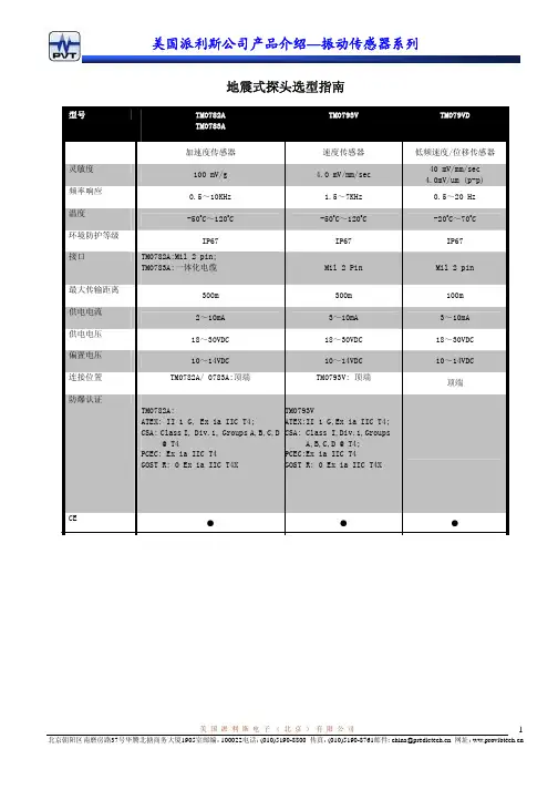
美国派利斯公司产品介绍—振动传感器系列美 国 派 利 斯 电 子 ( 北 京 ) 有 限 公 司北京朝阳区南磨房路37号华腾北搪商务大厦1905室邮编:100022电话:(010)5190-8800 传真:(010)5190-8761邮件: china@ 网址:1地震式探头选型指南美国派利斯公司产品介绍—振动传感器系列美 国 派 利 斯 电 子 ( 北 京 ) 有 限 公 司加速度传感器 TM0782A广泛应用于工业领域的压电晶体类型加速度传感器TM0782A-K 加速度传感器及套件由加速度探头和带5米电缆的接头组成。
TM0782A-K 加速度传感器及套件可以直接与派利斯公司的监测仪表连接,如DTM/TR 变送器、TM101变送保护表、PT580数字振动开关等,用于测量机壳振动,并输出加速度、速度、位移值。
技术参数电气指标灵敏度:100mV /g ±10%(25 oC ) 频响:0.5~10,000Hz (±3dB ) 最高振幅:50g 隔离:电路与外壳绝缘 噪声:0.0007g电源:2~10mA 恒流,18-30VDC 偏置电压:10 - 14VDC 共振频率:30kHz 最大传输距离:300米环境与物理指标温度区间:-50 oC ~+120 oC防护等级:IP67重量:90克 外壳材料:不锈钢 安装孔经:1/4-28UNF 安装力矩:29N*M 危险场合认证:ATEX : II 1 G, Ex ia IIC T4CSA : Class l, Div. 1, Groups A, B, C& D ,T4 PCEC :Ex ia IIC T4 GOST R: 0ExiallCT4X连接A :电源(红色电缆)B :公共端(白色电缆) COM :屏蔽层定货指南TM0782A-M加速度传感器(转接螺丝 1/4-28”→M6×1)TM0782A-E加速度传感器(转接螺丝 1/4-28” →1/4-28”)美国派利斯公司产品介绍—振动传感器系列美 国 派 利 斯 电 子 ( 北 京 ) 有 限 公 司北京朝阳区南磨房路37号华腾北搪商务大厦1905室邮编:100022电话:(010)5190-8800 传真:(010)5190-8761邮件: china@ 网址:3TM0782A-K-M加速度传感器套件包括: 9 TM0782A 加速度传感器 9转接螺丝(1/4-28” → M6×1) 9 TM0702-05TM0782A-K-E加速度传感器套件包括: 9 TM0782A 加速度传感器 9转接螺丝(1/4-28” →1/4-28”) 9 TM0702-05TM0782A-M-S9 加速度传感器(转接螺丝 1/4-28→M6×1) 9 本安防爆认证TM0782A-E-S9 加速度传感器(转接螺丝 1/4-28” →1/4-28”) 9 本安防爆认证TM0782A-K-M-S加速度传感器套件包括: 9 TM0782A 加速度传感器 9 转接螺丝(1/4-28″→M6×1)9TM0702-059 本安防爆认证 TM0782A-K-E-S加速度传感器套件包括: 9 TM0782A 加速度传感器9 转接螺丝(1/4-28″→1/4-28″)9TM0702-059 本安防爆认证.附件:(标准电缆长为 5 米, XX = 05) 建议选用 TM0702-XXTM0702-XX : MIL 铝插头, 带 XX 米电缆,直径7mm 。
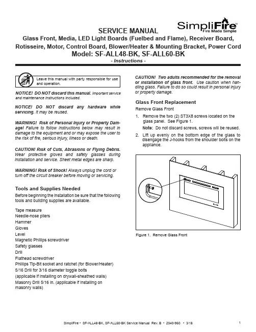
SERVICE MANUALGlass Front, Media, LED Light Boards (Fuelbed and Flame), Receiver Board, Rotisseire, Motor, Control Board, Blower/Heater & Mounting Bracket, Power CordCAUTION! Risk of Cuts, Abrasions or Flying Debris. Wear protective gloves and safety glasses duringinstallation and service. Sheet metal edges are sharp.NOTICE! DO NOT discard this manual. Important serviceand maintenance instructions included.NOTICE! DO NOT discard any hardware while servicing. It may be reused.WARNING! Risk of Shock! Always unplug the cord or turn off the circuit breaker before moving or servicing.Tools and Supplies NeededBefore beginning the installation be sure that the following tools and building supplies are available.Tape measure Needle-nose pliers Hammer Gloves LevelMagnetic Phillips screwdriver Safety glasses DrillFlathead screwdriverPhillips Tip-Bit socket and ratchet (for Blower/Heater)5/16 Drill for 3/16 diameter toggle bolts(applicable if installing on drywall-sheathed walls)Masonry Drill 5/16 in. (applicable if installing on masonry walls)Glass Front ReplacementRemove Glass Front1. Remove the two (2) ST3X8 screws located on theglass panel. See Figure 1. Note: Do not discard screws, screws will be reused. 2. Lift up evenly on the bottom edge of the glass to disengage the J-hooks from the shoulder bolts on the appliance.or property damage.Figure 1. Remove Glass FrontWARNING! Risk of Personal Injury or Property Dam-age! Failure to follow instructions below may result in damage to the equipment and or may expose the user to the risk of 昀椀re, serious injury, illness or death.Stone/Media Installation1. Remove Glass.2. Arrange the stone/media along the inset windowledge at the front of the appliance.Note: Extra media are provided and may bedistributed based on consumer preference. Not all media needs to be used.Glass Replacement (Continued)Installing Glass3. Install front panel. Locate the J-hooks on the back side of the glass on the four shoulder bolts on the appliance opening. Engage the shoulder bolts. See Figure 2.4. Press down on top edge of glass to fully engage J- hooks on the shoulder bolts.Note: Make sure the glass is fully attached to the 昀椀re-box so that the control panel can work properly.Figure 2. Glass Front Removal/Installation5. Thread the two (2) ST3X8 screws into the threaded holes on the glass panel. Check the alignment of the glass panel and securely tighten the screws. SeeFigure 3.Figure 3. Secure Glass Front1. Disconnect electrical service to the appliance. Forrecessed electrical installations that are hardwired,昀椀nd and shut-off service at the breaker. For wall-mounted installations that use a corded plug,disconnect the cord from the receptacle.2. Remove the glass front from the appliance. Use twopeople.3. Remove appliance the two screws in upper right andleft corners of the glass opening. Follow speci昀椀cinstructions from page 1 and 2 for removal of thefront glass. See Figure 4. CAUTION! Two adults recommended for the removal or installation of glass front. Use caution when han-dling glass. Failure to do so could result in personal injuryor property damage. Figure 4. Remove Upper Right & Left ScrewsPreparation for Component Installation4. Remove right and left side panels by turning thepanels inward. See Figure 5.Figure 5. Remove Right & Left Side Panels5. Using a 昀氀athead screwdriver, pry open the seventabs as shown in Figure 6. Pry the tabs upward at a30 degree angle. During this step, take care not toscratch or damage the glass panel behind the tabs.TABSFUELBED PLASTIC COVER Figure 6. Remove Plastic Cover6. Remove the fuelbed plastic cover that covers thefuelbed LED light strips. See Figure 6.LED Light Board InstallationThe LED Service Kit includes LED Light Boards for both the Fuelbed and the Flame effect.Determine which LED light set to be installed. See Figure 7.Figure 7. LED Light Board Identi昀椀cationLED FOR FUELBED1. Complete Steps 1-6 in Preparation for ComponentInstallation instructions. 2. Locate the Fuelbed LED Light Board cable. See Figure 8.LED LIGHT BOARD CABLE3. Unplug the LED Light Board cable. See Figure 9.LED LIGHT BOARD CABLEFigure 8. LED Light Board CableFigure 9. Unplug LED Light Board Cable4. Remove the LED light board from the bottom isolation columns. Starting at one end of the board use aLED FOR FLAMEFigure 10. Isolation Columns5. Remove and discard LED light board, replace with new LED light board. Install new LED light board by engaging the holes in the light board with the plastic barbs, and pressing into position. Reconnect the cables. See Figure 9.Fuelbed LED Light Board InstallationReceiver Board, Rotisseire, Motor, Flame LED Light Board, Control Board and Blower/ Heater Installation1. Complete Steps 1-6 in Preparation for ComponentInstallation instructions.3. Unplug Fuelbed LED Light Board, then lift it from theappliance set aside.Figure 12. Bracket Screw Location4. Remove seven (7) Phillips screws from the bracket. Remove the bracket. Set aside. See Figure 12.5. Carefully remove the glass panel. Rotate the top edge of the glass panel towards the opening, then lift out the the glass panel from the appliance. Set glass panel aside in a safe location, preferably a soft surface such as carpet or cardboard.Figure 11. Fuelbed LED Light Board Screw LocationReceiver Board Installation6. Locate the Receiver Board in the upper right side of appliance. See Figure 13.Figure 14. Receiver Board Cable7. Remove the Receiver Board from the isolationcolumns. Use a needle-nose pliers to compress the barbs on each isolation column.8. Unplug the cable, remove the Receiver Board and install with replacement board. See Figure 14.9. Reverse steps to complete installation.NOTE: The following steps (6-9) are only for re-placement of the Receiver Board.If replacing Rotisseire, Motor, Flame LED LightBoard, Control Board and/or Blower/Heater continue onto step 10.10. Remove two (2) Phillips screws at the bottom of the left and right side of the appliance opening. See11. Remove 14 Phillips screws at the top and bottom of the 昀氀ame screen. See Figure 16.12. Remove the 昀氀ame screen.Note: Be sure to place on a 昀氀at surface with the silk screen face-up. This is to prevent any distortion on the screen.13 Remove the center screw located in the the center of the Rotisseire. See Figure 17.14. Pull the Rotisseire to the left to disengage it from the motor, then remove the Rotisseire assembly.Figure 16. Flame Screen LocationFigure 17. Rotisseire Screw LocationIf replacing only the Rotisseire, install replacement part and reverse the installation steps.Be sure the 昀氀ame screen is installed correctly with the 昀氀ame silk screen to the outside and 昀氀ames at the bottom of the appliance.If replacing Motor continue to the next steps 15-18.Rotisseire InstallationIf replacing Flame LED Light Board continue to step 19.CAUTION! Risks of Cuts! Rotisseire has sharp edgesMotor InstallationThe motor is located in the lower right corner of the appliance.15. Remove the rubber shaft on the motor. See Figure 18.Figure 18. Rubber Shaft RemovalRUBBER SHAFT16. Remove the two screws on the motor. See Figure 19.Figure 19. Remove Motor Screws17. Unplug the motor cable connection. See Figure 20.Figure 20. Unplug Motor Cable18. Install replacement part and reverse the installation steps.Flame LED Light Board InstallationNOTE: The following steps (15-18) are only for re-placement of the motor.If replacing Flame LED Light Board, continue onto step 19.19. Remove screws used to attach the 昀氀ame screenFigure 21. Remove Flame Screen Bracket Screws.20. Remove 昀氀ame screen bracket.21. Unplug cable connection on each end of the LED Board. See Figure 22.Figure 22. Unplug LED Board Cable Connections22. Install replacement part and reverse the installation steps.Control Board Installation23. Remove the two (2) Phillips screws. After removing screws the mounting bracket can be lowered downto access the wires. See Figure 23.Figure 23. Remove Mounting Bracket Screws24. Unplug the 昀椀ve (5) pin and socket connectors between the Control Board and the wire harnesses. Tag and label the wire harnesses to ensure that wires will be reconnected correctly. See Figure 24.Figure 24. Unplug Control Board25. Install new Control Board and reverse the installation steps. Blower/Heater Installation26. Locate the four (4) screws on the mounting plate for the blower/heater module. See Figure 25.27. Remove the four (4) Phillips screws.Figure 25. Remove Mounting Plate Screws28. Drop the Blower/Heater module down on the shelf. See Figure 26.29. Reach up into the right end of the slot, and unplug the cable from the connector.Figure 26. Remove Blower/Heater30. Install new Blower/Heater and reverse the installationsteps.SHELFMasonry Wall •In the marked locations, drill 5/16 in. diameter x 2 in. deep holes. See Figure 30.• Insert the provided wall anchors into the holes. •Gently tap the anchors with a hammer until they are 昀氀ush with the wall surface.•With mounting hooks pointed up, attach the bracket to the masonry anchors with ST5X40 screws . SeeFigure 31.Figure 29. Installing Anchors in Hollow WallFigure 28. Toggle Bolt Installation through Mounting BracketFigure 30. Masonry Anchor PlacementFigure 27. 3/16 Toggle-Bolt Anchor•The toggle-bolt anchors are provided to accomodate the required anchor points based on the appliance. Use of toggle bolt anchors requires drywall thick-ness of minimum 1/2 in. and drilled holes size of 5/16 in. diameter.•Insert the bolt through the front side of the mounting bracket and thread the toggle onto it from the rear of the bracket. See Figure 28.•Fold the toggle wings 昀氀ush against the bolt and push them through a drilled hole until the toggle wings expand open on the other side. See Figure 29. •Pull back on the bolt and tighten. See Figure 29.Note: This product cannot be installed on a wall sheathed with drywall less than 1/2 in. thick, unless all six (6) anchor points in the mounting bracket align with structural framing members.WARNING! Risk of Damage or Personal Injury! Al-lowable pull-out and shear strength are 25% of ultimate values or less, as required by building authorities.Framed Wall •Locate the mounting bracket on the wall in thedesired location of the appliance. Level the bracket, then mark its location on the wall, including a mark-ing for each of the fastener holes in the bracket. •For each of the marked mounting point locations, determine which points align with a structural fram-ing member.•At the points where a wood or metal framing mem-ber exists, the ST5X40 screw can be installed directly into that structural member.•For every mounting hole that does not align with a structural framing member, a wall board toggle-bolt anchor must be used. See Figure 27.Direct Wall Mounting with Wall Mounting BracketThe wall mounting bracket can be installed on masonry walls such as those constructed of brick or concrete, or to framed walls constructed of wood or steel framing sheathed with gypsum wallboard, drywall, wood, etc. The method used to mount the mounting bracket is dif-ferent between masonry walls and framed walls. Refer to the following sections for more detail on the method applicable to this installation.11SimpliFire • SF-ALL48-BK, SF-ALL60-BK Service Manual Rev. B • 2040-960 • 3/18SimpliFire, a brand of Hearth & Home Technologies7571 215th Street West, Lakeville, MN 55044Please contact the SimpliFire customer/technical support hotline at 877-320-0730 with any questions or concerns.WARNING! Risk of Damage or Personal Injury! Do not use supplied masonry anchors on hollow walls,sheathed with wood, gypsum wallbaord, drywall or other materials.Figure 31. Bracket AttachmentWARNING! Risk of Fire, Electrical Shock and Injury! Ensure the power cord is not installed so that it is pinched or against a sharp edge and ensure that the power cord is stored or secure to avoid tripping and snagging.Power Cord Kit InstallationThe appliance power cord has a three pin NEMA-5-15P plug. The power cord should not be used unless a grounded receptacle is available.1. Remove the terminal block cover plate located on the right end of the appliance.2. Disconnect the terminal block from the three wires inside the appliance. Discard the terminal block cover plate.3. Connect the three appliance wires to the terminal block supplied with the power cord kit. See Figure 32.4. Replace cord kit terminal block cover plate and retaining screws. Plug cord into nearest outlet.Figure 32. Optional Power Cord Assembly InstallationLNR E DB L U EWire DiagramY E L L O W / G R E E N。
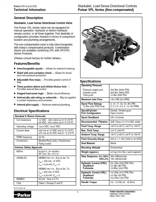
General DescriptionStackable, Load Sense Directional Control Valve The Pulsar VPL Series valve can be equipped for manual operation, hydraulic or electro-hydraulic remote control, or all three together. This flexibility of configuration provides freedom in terms of component location and plumbing arrangements.The non-compensated valve is fully interchangeable with today's compensated products. Combination stacks are available combining VPL with VP/VPO Series Products.(Please consult factory for further details.)Features/Benefits •Interchangeable spools Allows for reduced inventory.•Relief with anti-cavitation check Allows for shock and over pressure protection.•Adjustable flow stops Provides greater control of flow.•Three position detent and infinite friction lock Provides manual flow control.•Integral load sense logic Better circuit efficiency.•Intrinsically safe rating on solenoids May be applied in certain hazardous environments.•Internal pilot supply Reduces external plumbing. Electrical SpecificationsStandard & Marine SolenoidsCoil resistance12 VDC - 28.0 ohms at 21°C (70°F)24 VDC - 65.0 ohms at 21°C (70°F)Operating voltage12±3 VDC; 24±3 VDCCurrent draw430 mA at 12 VDC and 21°C (70°F)370 mA at 24 VDC and 21° C (70°F) PWM frequency33 HzConnectors WeatherPack (std.); Hirschmann,Flying LeadsIntrinsic Safety ApprovalsMSHA IA-627-0, IA-14238-0,XP Cert. No. 4111-0CENELEC NEMKO 90.114 - Eex ib IIA, T4,Imax= 300 mA, 12 VDC,L eq = 2.25 mH, Ceq= 0NEMKO 90.114 - Eex ib IIA, T4, Imax= 250 mA, 9 VDC,L eq = 2.25 mH, Ceq= 0NEMKO90.227 - Eex m II T4 CSA Class I, Groups C and D SpecificationsOperating PressurePressure supply port350 Bar (5000 PSI)Cylinder ports400 Bar (5800 PSI)Tank ports14 Bar (200 PSI)Maximum Inlet Flow190 LPM (50 GPM)Spool Flow Ratings6, 10, 17, 34, 53, 98 LPM15 Bar (220 PSI) Drop(1.5, 2.5, 4.5, 9, 14, 26 GPM) Spool/Cylinder Closed, Vented-open,Port Configuration Open (motor)Spool Deadband25% of strokeRecommended Filtration SAE Class 5 (17/14-ISO 4406) Fluid Temp. Range-40°C to 90°C (-40°F to 195°F) Max. Fluid Temp.121°C (250°F)Ambient Temp. Range-40°C to 88°C (-40°F to 190°F) Fluid Viscosity Range323 to 1.1 cSt (1500 to 30 SUS) Seal Material NitrileMounting Attitude UnrestrictedWeight (approx.) 4.5 kg (10.0 lbs.) work segment Step Response:0%-100%300 milliseconds100%-0%150 millisecondsHydraulic Control (VWL)24.1 Bar (350 PSI) PilotDeadband 5.5 Bar (80 PSI)Fullstroke15.2Bar (220 PSI)Hydraulic Control (VKL)14.5 Bar (210 PSI) PilotDeadband 3.5 Bar (50 PSI)Fullstroke10.3 Bar (150 PSI)Handle Torque0.6 - 2.5 Nm (5 - 22 lb/in)Code Description0None (VWL, VKL, VML only)112 V Pulsar, 12” flying leads312 V Pulsar with Weather Pack connector, 12” leads 524 V Pulsar, 12” flying leads724 V Pulsar with Weather Pack connector, 12” leads A 12 V Marine (Nemko), 100” flying leads B 24 V Marine (Nemko), 100” flying leadsJ 12 V Hirschmann, Large (DIN 43 - GDM Series)K 24 V Hirschmann, Large (DIN 43 - GDM Series)L 12 V Hirschmann, Small (G Series)M 24 V Hirschmann, Small (G Series)N 12 V Pulsar with 36” flying leadsP 12 V Pulsar with 36” leads, Weather Pack connector Q 24 V Pulsar with 36” flying leadsR 24 V Pulsar with 36” leads, Weather Pack connector S 11.2 V , Intrinsically safe w/male Electro connector T 11.2 V , Intrinsically safe w/Weather Pack connector X 12 V , XP Pulsar with male Electro connectorCode Description 2 2 way, C1 port 3 3 way, C1 port4 4 way, C1 and C2 portCode Description Q Electrohydraulic on-offP Electrohydraulic proportionalK Hydraulic remote (210 PSI pilot)W Hydraulic remote (350 PSI pilot)M Manual ControlCode DescriptionA 5.6 LPM (1.5 GPM)19.5 LPM (2.5 GPM)217.0 LPM (4.5 GPM)334.0 LPM (9.0 GPM)453.0 LPM (14.0 GPM)598.5 LPM (26.0 GPM)Note: For different flows Consult Factory.Code Description2Closed cylinder ports (CC)3C1 port (CC), C2 port (VOC)4Open cylinder ports (OC-Motor)7Vented open cylinder ports (VOC)Code Description1 2 pos. flow adjustment on C12 2 pos. no flow adjustments 3 3 pos. no flow adjustments4 3 pos. flow adjustments on C1 and C25 3 pos. flow adjustment on C1 only6 3 pos. flow adjustment on C2 only A 3 pos. Detent C1, C2 and CenterB Infinite position friction lock w/ center detentNote:Detent not available w/ flow adjustment option(Code A & B are VML only)Ordering Example:VQL5444-3035-26JOVValveSpool OperationLow Flow SectionSpool Flow RatingCylinder Port ConfigurationPilot ControlLSpool PositionsFlow DirectionsCode Description0Non-compensatedCode Description3Manual operator shaft only 4Manual operator with adapter and 6-inch handle 5Manual adapter only 6Marine handle adapter 7Marine handle adapter with 6-inch handleCode Description 4SAE ports 5BSPP portsCode Description 0No port cavity2Relief, with anticavitation check 3Anticavitation check5Float, 12 VDC or 24 VDC 6Defeat plugCode Pressure Setting A 50 Bar (750 PSI)B 63 Bar (950 PSI)C 80 Bar 1150 PSI)D 100 Bar (1450 PSI)F 125 Bar (1850 PSI)G 140 Bar (2050 PSI)H 160 Bar (2350 PSI)J 175 Bar (2550 PSI)K 190 Bar (2750 PSI)L 210 Bar (3050 PSI)M 230 Bar (3350 PSI)N 250 Bar (3650 PSI)P 280 Bar (4050 PSI)R 300 Bar (4350 PSI)S 320 Bar (4650 PSI)T 350 Bar (5050 PSI)O N/ACode Description 0No port cavity2Relief, with anticavitation check 3Anticavitation check5Float, 12 VDC or 24 VDC 6Defeat plug 0Section Pressure CompensatorManual OverrideDesign LevelC1Cylinder Port Option C2Cylinder Port OptionC2 PressureC1 PressureBulletin HY14-2101/US,3M, 9/02, PHDParker Hannifin Corporation Hydraulic Valve Division 520 Ternes AvenueElyria, Ohio, USA 44035Tel:(440) 366-5200FAILURE OR IMPROPER SELECTION OR IMPROPER USE OF THE PRODUCTS AND/OR SYSTEMS DESCRIBED HEREIN OR RELATED ITEMS CAN CAUSE DEATH, PERSONAL INJURY AND PROPERTY DAMAGE.This document and other information from Parker Hannifin Corporation, its subsidiaries and authorized distributors provide product and/or system options for further investigation by users having technical expertise.It is important that you analyze all aspects of your application and review the information concerning the product or system in the current product catalog. Due to the variety of operating conditions and applications for these products or systems, the user, through its own analysis and testing, is solely responsible for making the final selection of the products and systems and assuring that all performance, safety and warning requirements of the application are met.The products described herein, including without limitation, product features, specifications, designs, availability and pricing, are subject to change by Parker Hannifin Corporation and its subsidiaries at any time without notice.WARNINGPressure Drop C 1/C 2 ➔T (Meter Out Spools)Segment Flow vs.Load PressureWith Pressure Compensated Bypass Inlet (225 PSID)(Excess Flow can be limited with Spool Stroke Adjustment if required)Note:The flow rates for all spools will increase by 2 to 3% for every 10 PSI increasein differential pressure drop from the pump supply port to the load sensing port.All OptionsManual Control VMLPsC2L.S.C1TTRelief with AnticavitationAnticavitation CheckDigital PulsarDigital PulsarFlow Adjustment ScrewsLoad Sense Shuttle NetworkInterchangeable Spools6”Manual OperatorHydraulic Remote Control –VWL/VMLThe items described in this document are hereby offered for sale by Parker Hannifin Corporation, its subsidiaries or its authorized distributors. This offer and its acceptance are governed by the provisions stated in the "Offer of Sale".Offer of Sale。
派利斯中文使用手册第一章:介绍派利斯是一种强大的翻译工具,可以帮助用户实时翻译各种语言。
本手册将向您介绍派利斯的基本功能和使用方法。
第二章:安装和登录3.注册成功后,使用您的账户信息登录派利斯。
第三章:主要功能1.实时翻译:打开派利斯应用程序后,在输入框中输入您要翻译的文字或语句。
选择源语言和目标语言,然后点击“翻译”按钮即可实时翻译。
3.语音翻译:选择“语音翻译”功能。
按住录音按钮,说出要翻译的语句,松开按钮。
派利斯将尝试将语音转化为文字,并进行翻译。
第四章:高级功能3.字典功能:在派利斯应用程序中,选择“字典”功能。
输入要查询的单词或词组,派利斯将提供释义和示例用法。
第五章:常见问题1.为什么翻译结果不准确?派利斯尽力提供准确的翻译,但由于语言的复杂性和多义性,翻译结果可能存在误差。
2.如何提升翻译准确度?可以参考翻译结果的上下文,或尝试将长句拆分为更简洁的表达方式进行翻译。
第六章:使用技巧1.精确翻译:尽量提供清晰、准确的输入文本,以获取更准确的翻译结果。
2.听写模式:选择“语音翻译”功能后,点击“听写”按钮。
派利斯将在最终翻译前提供一段时间供您确认听写结果是否准确。
3.手写输入:在选择源语言后,可以通过点击键盘按钮来切换到手写输入模式,然后使用手指书写字母和汉字。
第七章:常用短语1.问候和礼节用语2.旅行用语3.饮食用语第八章:常用表达1.感谢与道歉2.询问与告知3.请求与回答第九章:技术支持本手册为派利斯中文使用手册,介绍了派利斯的基本功能、高级功能、常见问题、使用技巧以及常用短语和表达等内容。
希望通过本手册,用户能够更好地使用派利斯进行准确、便捷的翻译。

LPS 505N Programmable DC Power Supply User’s ManualLegal NoticesLegal NoticesThe information in this document is subject to change without notice. MOTECH makes no warranty of any kind with regard to this manual, including, but not limited to, the implied warranties of merchantability and fitness for a particular purpose. MOTECH shall not be held liable for errors contained herein or direct, indirect, special, incidental or consequential damages in connection with the furnishing, performance, or use of this material. MOTECH INDUSTRIES INC. 6F, No. 248, Sec. 3, Pei-Shen Road, Shen-Keng Hsiang, Taipei Hsien, 222, Taiwan Copyright Notices. Copyright 2005 MOTECH, all rights reserved. Reproduction, adaptation, or translation of this document without prior written permission is prohibited, except as allowed under the copyright laws.WarrantyWarrantyAll MOTECH instruments are warranted against defects in material and workmanship for a period of one year after date of shipment. MOTECH agrees to repair or replace any assembly or component found to be defective, under normal use during this period. MOTECH's obligation under this warranty is limited solely to repairing any such instrument, which in MOTECH's sole opinion proves to be defective within the scope of the warranty when returned to the factory or to an authorized service center. Transportation to the factory or service center is to be prepaid by purchaser. Shipment should not be made without prior authorization by MOTECH. This warranty does not apply to any products repaired or altered by persons not authorized by MOTECH, or not in accordance with instructions furnished by MOTECH. If the instrument is defective as a result of misuse, improper repair, or abnormal conditions or operations, repairs will be billed at cost. MOTECH assumes no responsibility for its product being used in a hazardous or dangerous manner either alone or in conjunction with other equipment. High voltage used in some instruments may be dangerous if misused. Special disclaimers apply to these instruments. MOTECH assumes no liability for secondary charges or consequential damages and in any event, MOTECH's liability for breach of warranty under any contract or otherwise, shall not exceed the purchase price of the specific instrument shipped and against which a claim is made. Any recommendations made by MOTECH for use of its products are based upon tests believed to be reliable, but MOTECH makes no warranty of the results to be obtained. This warranty is in lieu of all other warranties, expressed or implied, and no representative or person is authorized to represent or assume for MOTECH any liability in connection with the sale of our products other than set forth herein. MOTECH INDUSTRIES INC. 6F, No. 248, Sec. 3, Pei-Shen Road, Shen-Keng Hsiang, Taipei Hsien, 222, Taiwan Telephone : (886-2) 2662-5093 Facsimile : (886-2) 2662-5097 Email : instrument@ URL : Storage. Freight. Maintenance. Disposal※※※ Storage. Freight. Maintenance. Disposal ※※※Storage When don’t use the device, please pack it properly and store under a good environment. (The packing is no needed when the device under appropriate environment.) Freight Please use the original packing material when move the device. If the packing material is missing, please use the equivalent buffer material to pack and mark it fragile and waterproof to avoid the device damage during movement. And, please avoid heavy hitting to damage the device. Maintenance There is no maintenance operation for the general user (except for the note in the manual). Please contact our company or agent when the device occurred the user judgment abnormal. Don’t maintain by yourself to avoid occurred unnecessary danger and serious damage to the device. Disposal When the device in badly condition and can’t be used or repaired, please discard it according to your company disposal procedures or local legal procedures. Don’t discard arbitrary to avoid polluting environment. The device is precision equipment, please use qualified transportation as possible.IndexIndex1. Introduction ....................................................................................................1-1 1.1 1.2 2. 3. An Overview of Product ......................................................................1-1 Features..............................................................................................1-1Specification ...................................................................................................2-1 Notices before Using .....................................................................................3-3 3.1 Confirm Attachment before Using .......................................................3-3 3.2 3.3 3.4 3.5 3.6 3.7 3.8 The Description of Using.....................................................................3-3 Ambient Environment..........................................................................3-3 Storage ...............................................................................................3-3 Power-Line Voltage.............................................................................3-4 Fuse....................................................................................................3-4 Warming Up ........................................................................................3-4 End Test ..............................................................................................3-4 LPS 505N Panel Description ..............................................................4-1 Front Panel Description ......................................................................4-1 Rear Panel Description .......................................................................4-9 Voltage Setting....................................................................................5-1 Current Setting....................................................................................5-1 OVP ....................................................................................................5-1 OCP ....................................................................................................5-2 Rotary Controller (output on)...............................................................5-2 Preface ...............................................................................................6-1 Definition of Parameters .....................................................................6-1 Error/Event Queue ..............................................................................6-1 Compatible MOTECH LPS and PPS Protocol ....................................6-4 SCPI Compatiable Information............................................................6-9 SCPI Frequent Command...................................................................6-9 SCPI Command for Subsystem ........................................................6-10 Rules of Status Definition..................................................................6-314.Panel Description ...........................................................................................4-1 4.1 4.1.1 4.1.25.Operation Setting ...........................................................................................5-1 5.1 5.2 5.3 5.4 5.56.Remote Interface Protocol and Package Mode............................................6-1 6.1 6.2 6.3 6.4 6.5 6.5.1 6.5.2 6.67.Accessories ....................................................................................................7-1Introduction1. Introduction1.1 An Overview of ProductMotech LPS 505N is a triple outputs and programming DC power supply. LPS 505N comes with 12 bits resolution. Total 222W power output is provided by triple independent outputs. Double output provide 0~32V/3A, the other one provides 0~15V/5A 30W. For the 0~15V/5A output, users can use auto-ranging while constant 30W power output. This is the unique feature and it differs from other traditional power supplies. Those two 0~32V/3A outputs are required to output in serial or parallel mode. Tracking function is convenient and changeable for users in circuit application. LPS 505N has rotary and number key for user to easily operation. The configuration can be stored in memory (Max.100). Timer (1 sec~100 hrs) control when output can be switched off. It can provide the safety for burning room and electroplating application. OVP, OCP can be controlled and monitored by front panel. Users will not change the original setting because of the key lock function. When source and load change, LPS 505N has stable output due to 0.01% load and line regulation and max. 50 us respond time. Average measurement time is 50 ms to increase the production quantity.1.2 Features1. Triple output: Voltage Ranges : 0 ~ 32V (CH1&CH2) / 0 ~ 15V (CH3) Current Ranges : 0 ~ 3A (CH1&CH2) / 0 ~ 5A (CH3) Power Ranges : 0 ~ 96W (CH1&CH2) / 0 ~ 30W (CH3) The third output is an auto-ranging output. Users can change voltage and current as they want based on maximum 30W output. For example, output 15V/2A or 6V/5A voltage and current should be within the output range. 2. Digital rotary, number key, function key setting: Digital rotary can change voltage rapidly. Simulate the surge of the voltage output. It provides the solution for the trigger circuit testing. User can set up voltage by number key quickly. It differs from original VR adjusting. Function key provide users operation more friendly and easily. 3. Precious measurement on voltage & current: Besides precise output, LPS 505N provides voltage and current measurement.1-1IntroductionUsers can reduce the measurement equipment budget and space. 4. Memory and timer function: LPS 505N has large memory to memorize 100 settings. Operators are unnecessary to remember the settings. It can be easily to recall the settings. For safety issue, timer function will automatically switch off the machine when they are burning in burning room. LPS 505N can also provides time control good current resolution for electroplate application as customers’ need. 5. OVP, OCP & lock protection function: OVP, OCP provide the safety for the laboratory. The setting will not be changed due to the key lock function. 6. Series, parallel mode: In serial mode, CH1/CH2 can output maximum 64V with positive/negative output. It can be used for OP circuit design. In parallel mode, CH1/CH2 can output 6A maximum. 7. Dual tracking: Users only needs to setup CH1 output voltage and current, LPS 505N will output the same voltage/current at CH2. This is convenient to test two samples at the same time.1-2Specification2. SpecificationModel LPS 505NChannel NO. CH1 & CH2 CH3Output Voltage 0~32V 0~15V Output Current 0~3A 0~5AOutput Power96W 30W(CH3 Auto Ranging)Line Regulation ±(% of output +offset)Voltage 0.01% + 2mVCurrent 0.01% + 300uALoad Regulation ±(% of output +offset)Voltage ≦3mV ≦5mV Current 0.01% + 300uARipple and Noise ( 20Hz ~20MHz )Normal Mode Voltage 700uVrms / 7mVpp 1mVrms / 20mVpp Normal Mode Current <1mA <5mA ResolutionProgramming 10mV / 1mA 10mV / 2mA Readback 10mV / 1mA 3mV / 2mA Programming Accuracy ±(% output +offset)Voltage 0.05% + 20mV 0.05% + 6mV Current 0.05% + 3mA 0.05% + 4mA Readback Accuracy ±(% output +offset)Voltage 0.05% + 20mV 0.05% + 6mV Current 0.05% + 3mA 0.05% + 4mA Temperature Coefficient per℃ ±(% output +offset)Voltage <0.1% + 3mVCurrent <0.2% + 2mATracking Accuracy ±(% of output +offset)Voltage 0.1% + 40mVTransient Response Time <50uSStability﹐constant output & temperature ±(% of output +offset)﹐8hrs Voltage <0.2% + 2mVCurrent <0.1% + 1mASpecificationVoltage Programming SpeedRising Time at Full Load 3mSecRising Time at No Load 3mSecFalling Time at Full Load 8mSecFalling Time at No Load 250mSecGeneralAC Line Input VoltageRanges115/220 VAC ± 10%(50/60Hz)Temperature Ratings Operating( 0°C ~40°C),Storage (- 10°C ~70°C)Common-Mode Voltage ±240Vdc Dimensions ( W×H×D )mm (216 × 135 × 432 )Weight 6.5 kgLPS 505N Features:LCD display, triple independent output and display on LCDCH3 auto-ranging outputLow Ripple, Low NoiseNumber and function keyStore and recall settings (100)Timer (1 sec ~100 hours)Precise voltage and current measurementOVP, OCP and key lockSerial and parallel modeDual Tracking ModeAverage measurement time 50m secStandard RS232, USB interfaceNotices before Using3. Notices before Using3.1 Confirm Attachment before UsingPlease follows the below items to protect your rights as you receive this instrument.1. If there is ruin or scratch bad condition on product overlook.2. The standard attachment as table 7-1, please confirm if there is any missing.※If above conditions, please inform us for prompt service.3.2 The Description of UsingThe tester is an accurate instrument. Please read through this manual to prevent improper operation and arbitary using from causing this instrument damaged. Please calibrate once a year for keeping accuracy.3.3 Ambient Environment1. Do not use the tester in a dusty, vibrating, sunlight and corrosive gas. Pleaseuse this instrument under the ambient temperature is 0~40°C and the relative humidity is 20%~80%. If the temperature is over 40°C, please don’t use temporary until the temperature is down to normal. Please check to avoid the unit damage which result from over temperature.2. The tester is equipped with a cooling fan on the rear panel to keep the internaltemperature down, so adequate ventilation should be ensured. The tester should be located at least 10cm from any object or wall behind it. Do not block the ventilation holes to keep the tester in good precision.3. The tester has been carefully designed to prevent the noise from the AC powersource. However, it should be used in the noise-free environment as low as possible. If noise is inevitable, please install a power filter.3.4 StorageThe tester should be stored within the temperature range -10°C ~ 70°C, the relative humidity 80% RH. If the unit is not to be in use for a long time, please store it in the original or similar package and keep it from direct sunlight and humidity.Notices before Using3.5 Power-Line VoltageThe tester is an instrument which uses AC power 115V/220V 50Hz/60Hz. Before plugging in the power cord, make sure the power switch is in the off position and the voltage of the rear panel is the same as the required voltage.3.6 FuseThere is one fuse installed in the rear panel. When replacing the fuse, please notice the following:1. Please turn off the power and disconnect the AC power cord and all the otherconnections to the power supply.2. The checking of fuse can’t sure with the eyes, the testing value under 15Ωisnormal.3. When replacing the fuse, the cap jut out the rear panel on fuse stand using flattype screwdriver or pressing softly by hand.Mark Center Voltage Range Fuse115 115V 100V~125V Slow220 220V 200V~250V SlowWarning:For continues protection against fire hazard, replace only with thesame type and rating of fuse as specified.3.7 Warming UpThis tester activates at power on. However, in order to meet the accuracy in the specification, please warm it up for 30 minutes or longer.3.8 End TestWhen tests are done and the tester is not in use or need to leave for a while during usage, make sure to turn off the power switch.Panel Description4. Panel Description4.1 LPS 505N Panel Description4.1.1 Front Panel Description(1) Display:Display is a 20x4 yellow green backlight LCD(2) Rotary(ENTER):Rotary can adjust voltage and current. Users can press it as ENTERfunction.(3) M:Press M key to memory configuration display. Users can select whichsetting to store and recall by pressing STORE and RECALL key.(4) CH:Selecting CH1/CH2/CH3Panel Description(5) ON/OFF:Switching power output on or off of the instrument(6) Number Key:Input number by number key. To set the voltage or current, press the“V” or “A” key after the number input.(7) ►(STORE):When the output is on, press the key to move the cursor to select digitfor adjustment. Users can adjust the digit by rotary. In memory function,store into memory by pressing this key.(8) ◄(RECALL):When the output is on, press the key to move the cursor to select digitfor adjustment. Users can adjust the digit by rotary. In memory function,recall from the memory by pressing this key.(9) DISP:Press this key to select the display to show the voltage/current orpower/resistance readout.(10) V(Voltage):Press this key to set voltage after number input.(11) A(Current):Press this key to set current after number input.(12) Config:Press this key to enter the configuration setting. There 16 items to beset in this mode.1. Timer: The initial value is OFF. Press the rotary to enter timerconfiguration.Panel DescriptionA. Using rotary or ◄►to move the cursor onto the digit and input thenumber. Timer: 00:00:00 (HH:MM:SS)B. Switching CH1/CH2/CH3 by press CH key. Then press rotary toswitch ON/OFFC. Start Timer when press ON/OFF keyD. Press rotary + CLEAR to pause the timer. Restart by repeating thesame step2. TRACKING: The initial value is OFF, switch to ON by pressing therotary. The CH2 will have the same voltage and currentsetting as the CH1.3. OVP setting: Over voltage protection. Press the rotary to enter OVPConfiguration. Press “CH” to select CH1/CH2/CH3.Users can press ON/OFF to enable or disable OVP andinput the voltage value via the number keys. Pleaseremember to press rotary to save the settings.Panel Description4. OCP setting: Over current protection. Press rotary to enter OCPConfiguration. Press “CH” to select CH1/CH2/CH3.Users can press ON/OFF to enable or disable OCP andinput current value via the number keys. Pleaseremember to press rotary to save the settings.5. Baud rate: Transmission speed. Users can select baud rate for 1200,2400, 4800, 9600, 19200, 38400 by rotary.6. Interface: Transmission interface. Users can select RS232, USB,GPIB (Optional), LAN Port (Optional) by using rotary.Panel Description7. DHCP:This parameter is for LAN port setting. The default value is Offmode. You may change the mode by press the rotary. AtDHCP "On" mode, a dynamic IP address can be obtainedfrom the server.8. IP***.***.***.***:Setting of IP address. You may key-inthe right IP address for PPS 3210。

sSPPA-T3000,用户手册用户组态手册(共4册,第3分册)目,录1,,模板编辑器.................... 错误!未指定书签。
1.1,,启动模板编辑器 ...... 错误!未指定书签。
1.1.1,,退出模板编辑器.. 错误!未指定书签。
1.2,,常规布置................. 错误!未指定书签。
1.2.1,,工具栏.................. 错误!未指定书签。
1.2.1.1,,标准............... 错误!未指定书签。
1.2.1.2,,链接............... 错误!未指定书签。
1.2.1.3,,排列............... 错误!未指定书签。
1.2.1.4,,图形布局....... 错误!未指定书签。
1.2.1.5,,交互式绘图工具错误!未指定书签。
1.2.2,,模板的上下文菜单错误!未指定书签。
1.2.3,,单一、持久模式.. 错误!未指定书签。
1.2.4,,选项...................... 错误!未指定书签。
1.2.5,,窗口...................... 错误!未指定书签。
1.2.6,,保存视图.............. 错误!未指定书签。
1.3,,模板功能................. 错误!未指定书签。
1.3.1,,保存模板.............. 错误!未指定书签。
1.3.2,,以新的名字保存模板错误!未指定书签。
1.3.3,,打开库.................. 错误!未指定书签。
1.3.4,,编辑模板.............. 错误!未指定书签。
1.3.5,,创建新的模板...... 错误!未指定书签。
1.3.6,,删除模板.............. 错误!未指定书签。
1.3.7,,删除模板库节点.. 错误!未指定书签。
1.3.8,,将模板移动到另一个库节点错误!未指定书签。


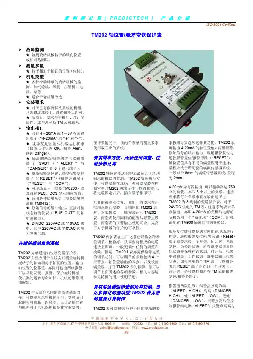
派利斯电子(北京)有限公司用户手册TM系列振动变送保护表安装操作维护TM-CAT-CHI-5.3-8815 COPY RIGHT PROVIBTECH 2008目录TM系列振动变送保护表的介绍 (2)I. 旋转机械监测和保护的发展 (2)II. 新功能 (2)III. 通用特点 (2)IV. TM 系列振动变送保护表选项 (3)TM101 机壳振动速度、加速度、位移变送保护表 (4)I. 概述 (4)II. TM101 振动变送保护表的技术参数 (4)III.订货选项. (5)IV.现场接线图 (7)V.现场报警调试 (8)VI. 现场操作 (9)VII. 4-20mA 标定(仅专业工程师操作) (10)TM系列振动变送保护表的介绍I. 旋转机械监测和保护的发展旋转机械监测的概念是二战以后由军方实验室推广而来,研究表明机械的故障严重影响生产,振动保护和状态监测的研究从50年代初至今已经得到完善的发展。
精确的监测旋转机械的运行状态主要有如下参量,轴承的径向振动、轴向位移、胀差和壳振,对于进一步的机械诊断,键相也是一个重要的测量参量。
典型的振动保护系统是由传感器和监测仪表组成的,传感器可分为趋进式涡流探头和测量绝对振动的加速度探头。
监测仪表将显示位移、速度、加速度单位。
由于集成电路的发展,DCS 和PLC已经被广泛的应用于机械的自动化控制上。
很多二次仪表的功能都可以通过DCS 和PLC来实现。
现在用户只需要一个4-20mA总振动信号输到上位机,上位机系统上实现的报警和停车是更可靠的报警方法之一。
通过使用派利斯特殊设计的振动保护表系列,只需传感器和监测表即可监测机组运行,TM表系列将输出4-20mA信号, 报警、停机,原始信号的缓冲输出,现场显示,遥控复位功能,报警点的设置和调整,以上所有功能都由体积很小的TM表实现。
II. 新功能1.报警和连锁延迟监测表有两极独立的报警和连锁的继电器输出,继电器类型为 SPDT,输出隔离1000VDC,节点容量 5A/220V。

USER GUIDEPRESYS PLUS ONBOARD PREAMPPresys Plus Quick Start1. Set the controls • Set volume and notch off. Set the bass, middle, treble and brilliance controls to center.2. Plug in • Connect the Presys Plus to an amplifi er or PA with a ¼-inch instrument cable. The battery light (batt) will fl ash once quickly to indicate it has switched on.3. T urn up • Raise the volume and adjust the bass, middle, treble and brilliancecontrols to your liking.23Presys Plus ControlsVolume • For the cleanest signal, set the volume knob as high as possible, without causing distortion or feedback.Bass • Boost here to add depth and weight to the sound of the guitar.Middle • Turn the middle knob all the way left for a smooth “scooped out” tone at high volume levels. Raise the middle knob to the right of center to add midrange “bite” to the sound.T reble • Boost to cut through the mix. Cut to mellow and subdue the sound. Brilliance • This slider can add shimmer and sparkle to your sound. It zeros in on crisp high frequency tones, the realm of harmonics and acoustic string sound. Lower the brilliance slider to reduce fi nger noise and fret buzz.Notch • Tune the notch fi lter to remove low-end feedback. Raise the volume until feedback occurs, then slowly turn the notch to the right until the feedback is eliminated.Phase • Use the phase switch to improve bass response at low volume and suppress feedback at high volume.T uner • Use the tuner lights as shown below to tune your instrument.Battery • When the batt indicator lights steadily it is time to change the bat-tery. To conserve power, unplug the instrument and turn off the tuner when not in use. Replace the battery by fl ipping open the preamp body using the latch located above the Fishman logo. Be sure to observe the correct polarity duringthis installation.“A” notebelow pitch“A” notein tune“A” noteabove pitch“A#” notein tune45Sample EQ SettingsFingerstyle“Scooped”MidThis will add fullness to the bass This setting emphasizes extreme bass and defi nition to the treble. and treble Strummer Cut Through the MixA good setting for strumming chords. When you need to be heard through aloudband.67FCC COMPLIANCE NOTICEThis equipment has been tested and found to comply with the limits for a Class B digital device,pursuant to Part 15 of the FCC rules. These limits are designed to provide reasonable protectionagainst harmful interference in a residential installation. This equipment generates, uses and canradiate radio frequency energy and if not used in accordance with the instructions, may cause harmful interference to radio communications and there is no guarantee that interference will not occur in a particular installation. If this equipment does cause harmful interference to radio or television recep-tion, which can be determined by turning the equipment off and on, the user is encouraged to try to correct the interference by one or more of the following measures: reorient or relocate the receiving antenna, increase the separation between the equipment and receiver, connect the equipment intoan outlet on a circuit different from that of the receiver. Consult the dealer or an experienced radio/TV technician if help is needed with interference.NOTE: FMIC and Fishman Transducers, Inc. are not responsible for unauthorized equipmentmodifi cations that could violate FCC rules, and/ or void product safety certifi cations.www.fi 513-300-184 Rev C 2-11。
NIPPON VALVE CONTROLS, INC. Instruction manualElectric Actuator PAX SP-1516GENERALA light weight, compact and long service life electric actuator built in high reliability and proportional motor.PAX : For AC power.PRODUCT CODEP A X- - - -(1) (2) (3) (4) (5)(1) ActuatorPAX (2) Torque050120(3) Voltage1 : 100 / 110 V2 : 200 / 220 V(4) OptionAK : Aluminum alloy motor coverC1 : Flexible cable(5) Operation modeNil : Mode AJ: Mode BActuator type (:Voltage code) PAX-050-PAX-120-Voltage 100 / 110 V AC ±10 % 50/60 Hz (Code: 1)200 / 220 V AC ±10 % 50/60 Hz (Code: 2)Rated torque [N m] 5 12Operation time [s] 14 / 12 (50/60 Hz) 30 / 25 (50/60 Hz)Power consumption [VA] 9.5Motor Synchronous motor (Triac control)Overload protection Impedance protectMethod of operation Proportional controlInput signal 4 to 20 mA / 1 to 5 V (Input resistance: 250 )Operation *¹ [Mode A] SHUT by decreased signal « OPEN by increased signal (Standard)[Mode B] SHUT by increased signal « OPEN by decreased signal (Option: J) Indication signal 0 mA : SHUT « 1 mA : OPEN (External load resistance: less than 3 k )Common in mode A / BResolution Less than 0.2 %Duty cycle 100 %Ambient temperature -20 to 55 ºCSpace heater 1 WManual operation Direct operation of actuator by loosening lock screwEnclosure Equivalent to IP65 (IEC 60529)Housing material Aluminum alloy die cast + Polycarbonate resin coverTerminal block For bare wire 0.2 to 1.5 mm² (AWG 26 to 16) Ground terminal: M3Conduct port G3/8 Cable gland (for 5 to 10.5 mm cable)*¹ Change by DIP switch. (Standard ® Mode B)WIRINGOPTIONAL PARTSSpecifications Code No. PAX Remarks Aluminum alloy motor cover AKFlexible cable (Approx. 300 mm long) C1Operation mode SHUT by 4 mA. (Decreased input signal) Nil Mode A (Standard) SHUT by 20 mA. (Increased input signal) J Mode BDIMENSIONADJUSTMENTHANDLING & STORAGEHANDLINGProper care in handling the actuator should be taken to prevent damage. Do not drop or throw it. STORAGEStore the actuator in the protected area from dust, moisture, and direct sunlight. If possible, actuator should be kept in the original packaging. CHECKINGCheck the product code, power supply, and voltage before installation.INSTALLATIONENVIRONMENT• Do not install in place where corrosive gas is present or where vibration is heavy (0.5 G or more).• When radiant heat causes the surface temperature of the control unit to exceed 55 °C, provide an appropriate shielding plate.• If there is a possibility that the fluid and drive part freeze, please take measures to prevent freezing. POSITIONINGShould be positioned through 90° upward from horizontal. Provide space around the product to allow manual operation, inspection and replacement work.Maintenance space for upper part of actuator PAX More than 90 mmOTHER NOTESUntil the wiring is completed there must be no condensation or flooding in the interior of the actuator, after piping. Protective caps on the cable gland are not waterproof.WIRING• Do not wiring outdoors on a rainy day.• Check the power supply and voltage.Connect the signal as shown in the wiring diagram. Do not connect unnecessarily terminal.• Use suitable flexible cable ( 5 to 10.5 mm).Lock and seal the cable completely to prevent condensation inside the actuator.• Built-in terminal block can clamp up to 1.5 mm in diameter without using solderless terminal.• Allow proper cable slack for maintenance.• Actuator should be electrically grounded.Use the terminal marked () inside the actuator. PREVENT DEW CONDENSATION• When installing the cover after wiring, perform the bolt by the temporary tightening procedure and the permanent tightening procedure to tightly and securely tighten the rubber packing so that water does not enter from the outside.• Tighten the cable gland nut so that there is no leakage from the wire entrance. CONTROL• Use shielded wire for signal wiring where high level noise is generated or when the wiring distance is long.• Control with a 1 to 5 V input signal becomes an input resistance 250 . Provide a voltage that can safely 20 mA or more than.• Check whether the MODE change DIP SW on a circuit board substrate is set up correctly.When wiring, if wiring of a signal is mistaken, it will not operate correctly. Contact us when you use two valve or more by one controller or indicator.• Input signal circuit is non-isolated.Do not connect DC (-) wire to other DC (-) common. • The input signal and operation mode are set as follows. (Factory shipped)Input signal 4 to 20 mA / 1 to 5 VOperation mode Mode AOperation SHUT by decreased signalOPEN by increased signal OPERATIONTESTING• Make sure that power supply voltage is correct. Also check operating position, wiring, speed and signals. • During trial operation, check that valve movement and output signal are correct.CONFIRM THE OPERATING CONDITION• Adjust fluid condition, controller setting, sensor etc. so that stable control is achieved.• When used in an unstable control state, the life of the actuator and the valve will be shortened.• The desired control state is stable at the target value. Adjust the PID setting value of the controller when overshooting the target value greatly, when not converging for a long time or hunting operation. Also, when the time delay is large, please consider the sensor position.ATTENTION• Be sure to set the DIP-SW before turning on the power supply.• Keep power supplied for built-in space heater to prevent condensation inside actuator.• Do not touch the moving parts of actuator in operation.• Never put anything on the actuator or make it into a foothold.Document is subject to change without notice.NIPPON VALVE CONTROLS, INC.1-21-19 Meieki minami, Nakamura-ku, Nagoya 450-0003 JAPANTEL: 81-52-582-6435 FAX: 81-52-582-6439MANUAL OPERATIONPRECAUTIONS• Manual operation should be a temporary operation. • Be sure to turn off the power before manual operation.NOTEFor manual operation, do not give more than the rated torque and make at a slow rate. Actuator might be damaged if excessive force is added.MAINTENANCE• To prevent electric shock, be sure to turn off the power when removing the actuator cover.• Do the routine maintenance at least once in half a year.Inspection items• Confirm operation of opening and closing.• Confirm that an actuator is not hot excessively.• Confirm existence of abnormal noise andvibration during operation.• Confirm whether screws are loose or not.• Confirm that water or condensation no remainsin the actuator. TROUBLE SHOOTINGProblem Cause SolutionActuatordoes notmove.Faulty wiring. Correct the wiring.Voltage andinput signal arenot coming.Check the voltage andinput signal.Incorrectvoltage.When it's burned out byexcess voltage, replacethe actuator.Connection orwiring is notcorrect.Correct the miswiringand misconnection.Be careful not tomistake the plus andminus of wiring.Short thecircuit, contactfailure.Review wires andconnection.Motor is tooold.Replace the actuator.Operationis unstable.Excess surgeor voltage wasapplied.Replace the actuator.Rainwaterentered theactuator.Added highharmonicsnoise from aninverter.Attachment a filter foreach inverter makeroption.Effect of highlevel noise.Use the shielded wireand ground the wiring.Separate signal wirefrom power line.Stop in themidposition.(Inputsignal’s1 to 5 V.)Signal voltagesource capacityshortage.Use a voltage sourcethat can be made toflow more than 20 mA.Please contact us.Stop in themidposition.Overloadprotector runsbecause ofover-torque.Motor protection circuitreturns by the signal ofoperation of anopposite direction. Turnon the power again.For more information contactNIPPON VALVE CONTROLS, INC. for consultation.。
WARNINGFOR YOUR OWN SAFETY, PLEASE READ THIS USER MANUAL CAREFULLY BEFORE YOUR INITIAL START-UP!SAFETY INSTRUCTIONSEvery person involved with the installation, operation & maintenance of thisequipment should:- Be competent- Follow the instructions of this manualBefore your initial start-up, please make sure that there is no damage caused duringtransportation. Should there be any, consult your dealer and do not use theequipment.To maintain the equipment in good working condition and to ensure safe operation, it is necessary for the user to follow the safety instructions and warning notes written in this manual.Please note that damages caused by user modifications to this equipment are notsubject to warranty.IMPORTANT:The manufacturer will not accept liability for any resulting damages causedby the non-observance of this manual or any unauthorised modification to the equipment.• Never let the power-cable come into contact with other cables. Handle the power-cable and all mains voltage connections with particular caution!• Never remove warning or informative labels from the equipment.• Do not open the equipment and do not modify the equipment.• Do not connect this equipment to a dimmer-pack.• Do not switch the equipment on and off in short intervals, as this will reduce thesystem’s life.• Only use the equipment indoors.• Do not expose to flammable sources, liquids or gases.• Always disconnect the power from the mains when equipment is not in use or beforecleaning! Only handle the power-cable by the plug. Never pull out the plug by pulling the power-cable.• Make sure that the available voltage is between 220v/240v.• Make sure that the power-cable is never crimped or damaged. Check the equipment and the power-cable periodically.• If the equipment is dropped or damaged, disconnect the mains power supply immediately.Have a qualified engineer inspect the equipment before operating again.• If the equipment has been exposed to drastic temperature fluctuation (e.g. aftertransportation), do not switch it on immediately. The arising condensation might damage the equipment. Leave the equipment switched off until it has reached room temperature.• If your product fails to function correctly, discontinue use immediately. Pack the unitsecurely (preferably in the original packing material), and return it to your Prolight dealer for service.• Only use fuses of same type and rating.• Repairs, servicing and power connection must only be carried out by a qualifiedtechnician. THIS UNIT CONTAINS NO USER SERVICEABLE PARTS.• WARRANTY; One year from date of purchase.OPERATING DETERMINATIONSIf this equipment is operated in any other way, than those described in this manual,the product may suffer damage and the warranty becomes void.Incorrect operation may lead to danger e.g.: short-circuit, burns, electric shocks,lamp failure etc.Do not endanger your own safety and the safety of others!Incorrect installation or use can cause serious damage to people and property.You should find inside the Laser carton the following items :1, Aries Laser 2, Power cable3, Instruction manualTechnical Specifications:DMX channels: 16Laser diodes: 1 x 70mW Green (532nM), 1 x 130mW Red (650nM) DPSS laserHigh speed scanner with extra wide scanner angleOperating modes: 1, Sound Activated2, Auto Run3, DMXPower consumption: 25WILDA compatiblePower supply: 240V - 50HzDimensions: 314 x 240 x 148mmWeight: 3.2KgsFuse: 2AFeatures:The Aries features 16 DMX channels and many laser patterns and animations that are ideal with or without fog.Back view:Identification:1, Keylock 2, Cooling fan3, DMX In4, DMX out5, Audio sensitivity knob6, Dipswitches7, Microphone8, Power input9, On/Off switch10, ILDA inputOperation modes:The Taurus has fours modes of operation as follows:1, Sound active modeTo select sound active mode set all dipswitches to OFF. You can now use the sensitivity control on the back panel to set the required sound level. With no music present, the laser diodes will turn OFF and will come back ON as soon as the music starts again.2, Auto pattern modeTo select auto pattern mode, set dipswitch 1 to the ON position and all others to OFF. TheAries will now cycle through all it’s internal geometric patterns. In this mode the laser diodes will remain on constantly until the power is turned OFF or the mode is changed.3, Auto animation modeTo select auto animation pattern mode, set dipswitch 1 + 2 to the ON position and all others to OFF. The Aries will now cycle through all it’s internal animation programmes such as awalking cat, running dinosaur and flying bird etc. In this mode the laser diodes will remain on constantly until the power is turned OFF or the mode is changed.4, DMX modeTo select DMX mode, set dipswitch 10 to ON. You can now set the required DMX address using dipswitches 1 to 9. Please refer to the chart below for DMX functions.DMX function chart:DMX Control ModeOperating in a DMX control mode environment gives the user the greatest flexibility when it comes to customising or creating a show. In this mode you will be able to control each individual trait of the fixture and each fixture independently.Setting the DMX addressThe DMX mode enables the use of a universal DMX controller. Each fixture requires a“start address” from 1- 511. A fixture requiring one or more channels for control begins to read the data on the channel indicated by the start address. For example, a fixture that occupies or uses 7 channels of DMX and was addressed to start on DMX channel 100, would read data from channels: 100,101,102,103,104,105 and 106. Choose a start address so that the channels used do not overlap. E.g. the next unit in the chain starts at 107.Set the start address using the group of dip switches located usually on the back of the fixture. Each dipswitch has an associated value. Adding the value of each switch in the ON position will provide the start address. Determining which switches to toggle ON given a specific start address can be accomplished in the following manner. By subtracting the largest switch value possible from the selected start address until zero is achieved.DMX-512: • DMX (Digital Multiplex) is a universal protocol used as a form of communication between intelligent fixtures and controllers. A DMX controller sends DMX data instructions form thecontroller to the fixture. DMX data is sent as serial data that travels from fixture to fixture via the DATA “IN” and DATA “OUT” XLR terminals located on all DMX fixtures (most controllers only have a data “out” terminal).DMX Linking: • DMX is a language allowing all makes and models of different manufactures to be linked together and operate from a single controller, as long as all fixtures and the controller are DMX compliant. To ensure proper DMX data transmission, when using several DMX fixtures try to use theshortest cable path possible. The order in which fixtures are connected in a DMX line does not influence the DMX addressing. For example; a fixture assigned to a DMX address of 1 may be placed anywhere in a DMX line, at the beginning, at the end, or anywhere in the middle. When a fixture is assigned a DMX address of 1, the DMX controller knows to send DATA assigned to address 1 to that unit, no matter where it is located in the DMX chain.DATA Cable (DMX cable) requirements (for DMX operation):• The Equinox Aries laser can be controlled via DMX-512 protocol. The DMX address is set on the back of the unit. Your unit and your DMX controller require a standard 3-pin XLR connector for data input/output (figure 1).Figure 1Also remember that DMX cable must be daisy chained and cannot be split.Further DMX cables can be purchased from all good sound and lighting suppliers or Prolight dealers.Please quote: CABL10 – 2M CABL11 – 5M CABL12 – 10MNotice: • Be sure to follow figures 2 & 3 when making your own cables. Do not connect the cable’s shield conductor to the ground lug or allow the shield conductor to come in contact with the XLR’s outer casing. Grounding the shield could cause a short circuit and erratic behaviour.Special Note: Line termination: • When longer runs of cable are used, you may need to use a terminator on the last unit to avoid erratic behaviour.Using a cable terminator (part number CABL90) will decrease the possibilities of erratic behaviour.5-Pin XLR DMX Connectors: • Some manufactures use 5-pin XLR connectors for data transmission in place of 3-pin. 5-Pin XLR fixtures may be implemented in a 3-pin XLR DMX line. When inserting standard 5-pin XLR connectors in to a 3-pin line a cable adaptor must be used. The Chart below details thecorrect cable conversion.Termination reduces signal transmission problemsand interferance. it is always advisable to connect aDMX terminal, (resistance 120 Ohm 1/4 W) betweenpin 2 (DMX-) and pin 3 (DMX+) of the last fixture.DMX Dip Switch Quick Reference ChartDip Switch PositionDip Switch position DMX AddressClass 3B Laser Safety GuideWarningClass 3B Lasers have the potential to harm eyesight if viewed directly and can also be harmful at long distances.Any unit that contains a laser diode has to be classified depending upon the light output that someone may be exposed to. All laser products are classed as defined in theLaser Product Safety Standard (BS/EN 60825.1). The classes range from the safest, which is Class 1, through to the most hazardous, which is Class 4. A laser diode that emits more than 5mW of light and less than 500mW can be classified as a Class 3B product.Operation and installation NotesLaser effects should only be installed and operated by persons who have been trained in how to operate laser effects safely.Laser effects should be located in a safe and secure position in the venue, so that once installed it cannot be tampered with by unauthorized users.Before operation the path of the laser beams should be taken into account in respect to how the beams will scan the viewing audience.If direct audience scanning is to be used then the laser energy levels from the effects needs to be calculated.HealthIf used responsibly and in accordance with the relevant guidance issued by the Health and Safety Executive a laser effect will not present a hazard to those viewing the show as long as the laser beams are projected over the heads of the viewing audience. When laser effects are directed into the audience area it becomes difficult to tell if the effects are causing harm.Class 3B laser beams can be harmful to eyesight if viewed directly The injury that a Class 3B laser can inflict is dependant upon several varients, including the amount of time the laser beam enters the eye for, the intensity of beam and what part of the eye that actually receives the beam. The part of the eye which is most susceptible to receive damage from the beam is the retina. The retina is the part of the eye that receives the light signals that are sent to brain. All light entering the eye gets focused onto the retina.Normal light sources including halogen lamps are not usually harmful to view. Lasers are different in the fact that they can get the beam focused down to a very small point on the retina which can burn holes on the back wall of the eye. There are no pain receptors on the retina and the damage can happen in less time than it takes for a person to blink so the person will be not be aware of any damage taking place. Damage to the retina cannot be repaired and therefore is permanent. Symptoms include severe loss of sight and unnoticeable vision loss.Licensing and LawsThere are no U.K. “laser laws” or any “laser licenses” that need to be obtained inorder to own or operate a laser for lightshow use. Detailed and specific guidance is issued by the Health and Safety Executive in the form of a book called HS(G)95 The Radiation Safety of Lasers Used for Display Purposes.Class 3B Laser Safety FeaturesClass 3B laser products need to be fitted with specific safety features. These features are issued in the British Standard on Laser Product SafetyBS/EN 60825-1 and are a needed for the product to meet CE approval.The important warnings are listed below:-1) Emissions Indicator2) Remote Interlock Connector3) Laser Safety Warning LabelsSummary of each FeatureClass 3B lasers need to contain three very importantLaser Safety Warning Labels; the starburst symbol, aperture label, and the warning/classification label. The starburst is used to indicate that the product is a laser product. The aperture label is located next to the appature to show where the laser emits it’s beam(s). The warning/classification label details the class of the laser product, the maximum output power, and the wavelength(s) (colours) of the laser, along with a“Laser Radiation – Avoid Exposure To The Beam” warningThe Remote Interlock Connector will only allow the laser to function when the two pins are shorted together. For lightshow use it is recommended by HS(G)95 laser safety guidance laser effects can be overridden by a remote Emergency Stop switch. The remote interlock connector provides a convenient way for such a switch to be easily added to the laser system, to provide this control.The emissions indicator is fitted to indicate when the laser is ready to produce a light output.Audience ScanningAudience Scanning is when laser beams are directed at the viewing audience. Because the laser output beam can scan people’s faces it carries a risk that it could cause damage to eyesight, if over exposed to the laser beam.Maximum Permissible Exposure (MPE)The amount of laser light that a person can be exposed to without it causing harmto eyesight is known as the Maximum Permissible Exposure or MPE. These levelsare set down by the British Laser Safety Standard BS/EN 60826-1. When peopleare exposed to laser light output which is above the MPE, it may potentially pose a risk of causing eye damage. Calculating what the MPE and exposure level is for a given laser effect is quite a complicated process and it is dependant on a whole number of factors and conditions. The laser safety standard BS/EN 60825-1 contains the information and data required to calculate these levels.Laser Safety Officer The BS/EN60825-1 Laser Safety Standard recommends that all venues that use, or businesses that work with Class 3B laser products, should appoint a Laser Safety Officer (LSO). The Laser Safety Officer should be aware of the many safety issues when using lasers, and will also be responsible for overseeing how the laser is used. In smaller businesses, the (LSO) could be the installer, operator or owner etc.Separation DistancesHealth and Safety guidance details that for supervised installations of lasers which are above the Maximum Permissible Exposure (MPE) should not be accessible to persons in the audience. Also recommended is an area where the MPE may not be exceeded and extends from 3m above to2.5m laterally from any point in the venue where the public may have access during the lightshow. The illustrations below show the separation distances.Separation Distance Drawing:Note. The 3 metre height specified is not the height of the actual laser unit, but itrefers to the height of the laser beams emitted.Hazard Distances All lasers for display porposes feature a characteristic called the hazard distance for direct viewing (NOHD). The (NOHD) is distance at which viewing the laser directly is no longerconsidered a hazard. Note at any point between the laser unit and the calculated hazard distance, it may be hazardous to directly view the laser beams. Exposing the eye to the laser directly from outside the hazard distance is considered to be no longer a risk.The most dangerous senerio is to look directly at a static single beam, because all the light energy is concentrated into one small point. The hazard distances for various different powers of Class 3B laser are shown in the table below.Laser Output PowerHazard Distance Note - The above values in the table have been calculated assuming the characteristics of a typical laser, which has a beam spread of 2mradians. Not all laser units have the samespecification.Remember: Static laser beams are hazardous for long distances so it is recommended that the laser beams are projected overhead and not into the viewing audienceLaser Safety BooksThe Radiation Safety of Display Laser Installations HS(G)95Published by HSE Books 1996 ISBN 0 7176 0691Health & Safety ExecutiveWebsite - Laser display safety guidance page - /pubns/INDG224.htmHealth Protection Agency Website - 10mW 30mW 50mW 100mW 250mW 450mW 12m 20m 25m 36m 56m 76m。
PE60M3N06J-M0_102015Electric Pump Instruction ManualMODEL: PE60M3N06J & PE60M4N06JSFA Companies 10939 N. Pomona Ave. Kansas City, MO 64153Tel: 888-332-6419 * Fax: 816-448-2142E-mail:******************************:Model PE60M3N06JMaximum Operating Pressure 10,000 PSIThis is the safety alert symbol. It is used to alert you to potential personal injury hazards. Obey all safety messages that follow this symbol to avoid possible injury or death.SAFETY AND GENERAL INFORMATIONSave these instructions. For your safety, read and understand the information contained within. The owner and operator shall have an understanding of this product and safe operating procedures before attempting to use this product. Instructions and safety information shall be conveyed in operator's native language before use of this product is authorized. Make certain that the operator thoroughly understands the inherent dangers associated with the use and misuse of the product. If any doubt exists as to the safe and proper use of this product as outlined in this factory authorized manual, remove from service immediately.Inspect before each use. It is recommended that, prior to each use, an inspection be done by qualified personnel and that any missing or damaged parts, decals, warning / safety labels or signs be replaced with factory authorized replacement parts only. Any pump that appears to be damaged in any way, is worn, leaking or operates abnormally shall be removed from service immediately until such time as repairs can be made. Any pump that has been subjected to a shock load (a load dropped suddenly, causing the system pressure to exceed 10,000 PSI), shall be removed from service immediately until checked by qualified personnel. Owners and operators of this equipment shall be aware that the use and subsequent repair of this equipment does require special training and knowledge.PRODUCT DESCRIPTIONThis Pump is engineered to meet most industrial standards for Performance and Safety. Its allows quick displacement of hy-draulic fluid under no load conditions and easy pumping in loaded conditions. This electric hydraulic pump supplies compressed hydraulic fluid to compatible single acting applications ONLY. Such applications include rams, presses, spreaders, compactors and crimping machines, anywhere that 10,000 PSI of single acting fluid pressure is needed. Special skill, knowledge and training may be required for a specific task and the product may not be suitable for all the jobs described above. Unsuitable applications would include applications that call for a device to move, level or support persons, animals, hazardous materials, mobile homes/ dwellings in general, mirrors and/or plate glass, and/or to connect/secure hatches, components, etc. between bulkheads. The user must make the decision regarding suitability of the product for any given task and assume the responsibility of safety for himself/herself and others in the work area.Figure 1 - Typical 3-way 3-position PE series Electric Pump Components (PE60M4N06J shown)Electric Motor ON/OFF SwitchControl Valve Electric MotorControl BoxControl Valve Lever Drain PlugReservoirPower CordOil Output PortsBEFORE USERead, understand, and follow all printed materials carefully before attempting to assemble or operate these pumps. NOTICE: E-Pumps are shipped dry. Add oil before use. Electrical Connections:Compare motor nameplate against power availabilityto prevent motor burnout and dangerous electrical overloading. The motors are wired for 380 volts unless otherwise specified.DANGER: Motor, connections and remote on/off switchare energized components containing line voltage.Ensure supply is grounded and GFI protected. Hydraulic Connections:1. Check oil level, add oil if necessary.2. Make sure system fittings and connections are tight and leak free.3. Place control valve lever in the middle (Neutral/Hold) position to prevent accidental lifting or moving of load.4. To start the motor: Toggle the ON/OFF switch located on the control box to 'ON' position OR for momentary use: Leave control box switch in the 'OFF' position and toggle remote ON/OFF pendant switch.5. It is recommended to use to ON/OFF switch at the control box to let the pump idle for a few minutes before putting into operation.WARNING: This pump is for use with a single acting cylinder ONLY! Connect one hose from either pump oil output port to the input port of a single acting application such as a cylinder. Block the unused output3. Remove vent cap on the top plate of the reservoir.4. Use a funnel to fill reservoir to about 2" from top of reservoir plate.5. Wipe up any spilled fluid and reinstall the vent cap.Changing Hydraulic Oil1. For best results, change hydraulic oil once a year.2. Remove drain plug, tilt the pump then pour used fluid into a sealable container.3. Dispose the hydraulic oil in accordance with local regulations.4. Fill hydraulic oil, then reinstall vent cap.CleaningClean oil filter screen periodically with nonflammable solvent, then blow dry before reassemble back to pump.Storage1. When not in use, depressurize and disconnect hydraulic hoses from application.2. Wipe clean, thoroughly.3. Store in clean, dry environment. Avoid temperature extremes.4. For transportation or long term storage, shield pump with a protective cover.TROUBLESHOOTINGA system failure may or may not be the result of a pump malfunction. The following information is intended to be used as an aid in determining if a problem exists. Pumps should be repaired only be repaired by authorized BVA Service Center.MAINTENANCE1. Keep areas around pump unobstructed in order to provide good air flow around the motor and pump. Try keep the motor and pump as clean as possible.2. Inspect hoses and connections daily. Replace damaged components immediately with BVA Hydraulics replacement parts only.3. Tighten connections as needed. Use non-hardening pipe thread compound when servicing connections.4. Check hydraulic oil level every 40 hours of operation. Add hydraulic oil if necessary.5. Completely change the hydraulic oil every 300 hours of operation. Change the oil more frequently when pump is used in an extremely dusty environment or when the oil has been overheated. Use only good quality hydraulic oil. We recommend BVA hydraulic oil (F01 & F05), ISO 46 or equivalent. To order the oil, refer to service parts section. Use only the manufacturers recommended hydraulic oil. Use of other hydraulic oil may result in pump failure and will void warranty.Adding Hydraulic Oil1. Make sure electric motor is OFF.2. Depressurize and disconnect hydraulic hose from application.SymptomPossible CausesCorrective ActionMotor will not start• No power or wrong voltage • Damaged power cord • Tripped circuit breaker • Loose or faulty wiring• Check the power supply & voltage • Contact Customer Service• Ensure electrical supply is adequate • Contact Customer ServiceErratic cylinder action • Air in system or pump cavitation • External leak• Internal hydraulic leak • Follow pump instructions for bleeding air • Tighten all connections • Contact Service Center Pump fails to maintain pressure• External leak• Internal hydraulic leak• Pump or valve malfunction• Tighten all connections • Contact Service Center Cylinder extends partially• Hydraulic oil level too low in pump • Load is above the capacity of system • Cylinder is sticking or binding • Fill and bleed the system • Use the correct equipment • Contact Service CenterCylinder moves slower than normal • Loose connection or coupler• Restricted hydraulic line or fitting • Pump not working correctly • Cylinder seals leaking • Tighten• Clean and replace if damaged• Check pump operating instructions • Replace cylinder Cylinder leaks hydraulic fluid • Worn or damaged seals• Replace cylinderCylinder will not retract or retracts slower than normal• Loose couplers• Weak or broken retraction springs • Cylinder damaged internally • Pump reservoir too full• Tighten couplers • Replace cylinder • Replace cylinder• Drain hydraulic fluid to correct level Motor cuts out• Extension cord too long • Faulty motor• Overheated motor trips circuit breaker• Replace• Replace or repair• Allow motor to cool, reset circuit breakerParts List Service PartsINCLUDES MODEL NUMBER: PE60M3N06J & PE60M4N06JSFA Companies 10939 N. Pomona Ave. Kansas City, MO 64153Tel: 888-332-6419 * Fax: 816-448-2142E-mail:******************************:Not all components of the pump are replacement items, but are illustrated as a convenient reference of location and position in the assembly sequence.Item Part Number Description QTY.1E35-4-9320-103 3 H.P 3PH. MotorAssembly11-1649-1-0120-030Bolt41-2605-3-0120-025Gasket42E35-1-2000-102 3 H.P. Motor PumpAssembly13E35-4-9015-108Reservoir Assembly13-1E11-3-6005-100Screen13-2E11-6-7002-107Pipe Nipple1 3-3E11-6-3007-107Drain Line1 3-4601-3-0064-106Gasket16 3-5649-1-0060-407Bolt16 4D09-0-1002-100 3 Way / 3 Position Valve132 4333534231112311Pump AssemblyPART: E35-1-2000-102SFA Companies 10939 N. Pomona Ave. Kansas City, MO 64153Tel: 888-332-6419 * Fax: 816-448-2142E-mail:******************************:Not all components of the pump are replacement items, but are illustrated as a convenient reference of location and position in the assembly sequence.Parts List Pump Piston SetPART: E30-4-4000-105SFA Companies 10939 N. Pomona Ave. Kansas City, MO 64153Tel: 888-332-6419 * Fax: 816-448-2142E-mail:******************************:Not all components of the pump are replacement items, but are illustrated as a convenient reference of location and position in the assembly sequence.3 26745 61Item Part Number Description QTY. 1E30-6-4000-107Piston1 2*Spring1 3N/A Piston Block1 4H18-6-8103-104Washer1 5E05-6-4002-102Hex Head Plug1 6*O-Ring2 7*Ball1 8*O-Ring2 *E15-3-9940-101Piston Block Assembly Repair Kit1Electric Pumps Gear Pump AssemblyPART: E15-4-6030-103SFA Companies 10939 N. Pomona Ave. Kansas City, MO 64153Tel: 888-332-6419 * Fax: 816-448-2142E-mail:******************************:Not all components of the pump are replacement items, but are illustrated as a convenient reference of location and position in the assembly sequence.Parts ListElectric Pumps Safety Valve SetPART: E05-4-8000-106SFA Companies 10939 N. Pomona Ave. Kansas City, MO 64153Tel: 888-332-6419 * Fax: 816-448-2142E-mail:******************************:Not all components of the pump are replacement items, but are illustrated as a convenient reference of location and position in the assembly sequence.12111089675215225215204312131415161718231824182518241920Item Part Number Description QTY .1E05-6-8008-104Parker Hex Plug 12*Metal Seal 13*Tapered Spring 14601-7-0008-009Chrome Steel Balls 1/4"15E05-4-8002-100Stick Valve Assy.16N/A Block-unloading 17*O-ring 28E05-6-8001-201Unloading PIn19*Chrome Steel Balls 3/8"110E05-6-8005-108Ball Retainer 111*Low Pressure Spring1Item Part Number DescriptionQTY .12641-1-0158-105Socket Head Set Screw 113641-1-0127-104Socket Head Set Screw 114*High Pressure Spring 115E05-6-8004-106Relief Ball Retainer 116E05-6-8006-100Hollow Set Screw 117*Chrome Steel Balls 3/16"118E05-4-8003-102High Pressure Seat Assy.119649-1-0063-302Socket Head Cap Screw 420641-1-0060-007Hollow Set Screw 2*E05-3-9980-105Pressure Adjusting Assy.Repair Kit111LIMITED LIFETIME WARRANTYBVA Hydraulics®, represented in the United States by SFA Companies [“SFA”] warrants this product to be free from defects in material and workmanship for the life of the product as long as the original purchaser owns the product. The warranty is non-transferable and is subject to the terms, exclusions, and limitations described below:• Damaged components, including but not limited to bent rams, dented or crushed cylinder walls, broken welds or couplers as well as worn out seals, o-rings and springs are the result of misuse and not covered by warranty and BVA Hydraulics will not provide any warranty credit for such damaged components.• This warranty does not cover ordinary wear and tear, overloading, alterations (including repairs or attempted repairs not performed by BVA Hydraulics or one of its authorized personnel), improper fluid use, or use of the product in any manner for which the product was not intended or the use of which is not in accordance with the instructions or warnings provided with the product.• In the unlikely event that a BVA Hydraulics product fails due to material defect in workmanship, you may contact SFA for dis-position. In such cases, the customer’s sole and exclusive remedy for any breach or alleged breach of warranty is limited to the repair or replacement of the defective product.• Under no circumstances is BVA Hydraulics liable for any consequential or incidental damage or loss whatsoever.• THIS WARRANTY IS LIMITED TO NEW PRODUCTS SOLD THROUGH AUTHORIZED DISTRIBUTORS AND OTHER CHAN-NELS DESIGNATED BY BVA HYDRAULICS. NO AGENT, EMPLOYEE OR OTHER REPRESENTATIVE OF BVA HYDRAU-LICS IS AUTHORIZED TO MODIFY THIS WARRANTY.• THE FOREGOING IS EXCLUSIVE AND IS IN LIEU OF ALL OTHER EXPRESS AND IMPLIED WARRANTIES, INCLUDING BUT NOT LIMITED TO THE IMPLIED WARRANTIES OF MERCHANTABILITY AND FOR A FITNESS FOR A PARTICULAR PURPOSE.• Components not manufactured by BVA Hydraulics including certain motor systems, gasoline engines, and other are not covered by this warranty and instead are covered by the manufacturer’s separate manufacturer’s warranty provided in the package.• BVA Hydraulics’ liability in all cases is limited to, and will not exceed the purchase price paid for the product.SFA Companies10939 N. Pomona Ave. Kansas City, MO 64153Tel: 888-332-6419E-mail:***********************12。