mpls-bgp实验
- 格式:docx
- 大小:125.82 KB
- 文档页数:13

实验十、BGP实验实验要求:1、掌握BGP的基本配置方法。
2、掌握如何查看BGP的各种配置信息。
3、掌握基于回环口的BGP的邻居关系建立的配置方法。
4、理解需要使用回环口为目的。
5、理解BGP同步功能的作用和配置。
6、掌握使用指向NULL0接口的静态路由的汇总配置方法。
7、掌握使用聚合属性的路由汇总配置方法。
实验拓扑:根据实验要求,实验拓扑如图10-1所示。
图10-1 BGP实验拓扑注:R1和R2属于自治系统65001,R3属于自治系统65002实验步骤:1、根据实验拓扑,对路由器各接口配置IP地址,使直连链路相互间可以进行通信。
2、在R1和R2上配置EIGRP,关闭自动汇总。
参考命令如下:R1(config)#router eigrp 50 50修改为自己学号后两位R1(config-router)#network 192.168.1.0R1(config-router)#network 1.0.0.0R1(config-router)#no auto-summaryR2(config)#router eigrp 50 50修改为自己学号后两位R2(config-router)#network 192.168.1.0R2(config-router)#network 2.0.0.0R2(config-router)#no auto-summary3、首先在R1和R2配置BGP协议,使用回环口创建邻居关系,参考命令如下:R1(config)#router bgp 65001 65001修改为65000+自己学号后两位R1(config-router)#neighbor 2.2.2.2 remote-as 65001 65001修改为65000+自己学号后两位R1(config-router)#network 1.1.1.1 mask 255.255.255.255R1(config-router)#network 172.16.0.0 mask 255.255.255.0R1(config-router)#network 172.16.1.0 mask 255.255.255.0R1(config-router)#network 172.16.2.0 mask 255.255.255.0R1(config-router)#network 172.16.3.0 mask 255.255.255.0R1(config-router)#network 192.168.1.0R2(config)#router bgp 65001 65001修改为65000+自己学号后两位R2(config-router)#neighbor 1.1.1.1 remote-as 65001 65001修改为65000+自己学号后两位R2(config-router)#network 2.2.2.2 mask 255.255.255.255R2(config-router)#network 192.168.1.0R2(config-router)#network 192.168.2.04、配置后在路由器R1中查看BGP邻居关系和汇总信息,参考命令如下:R1#show ip bgp neighborsR1#show ip bgp summary问题1:R1中邻居关系的状态是什么?5、查看路由器R1和R2的BGP的路由链路数据库信息,参考命令如下:R1#show ip bgp ipv4 unicast问题2:在数据库中是否有非直连链路信息?6、在路由器R1和R2中分别指定回环接口建立邻居关系,参考命令如下:R1(config)#router bgp 65001 65001修改为65000+自己学号后两位R1(config-router)#neighbor 2.2.2.2 update-source lo1 lo1为地址1.1.1.1的接口R2(config)#router bgp 65001 65001修改为65000+自己学号后两位R2(config-router)#neighbor 1.1.1.1 update-source lo0 lo0为地址2.2.2.2的接口问题3:再次查看R1的邻居关系,邻居关系状态为什么?问题4:在路由器R2中查看路由链路数据库,能否看到R1上面的路由?如果能看到的话这些路由是否为最佳路由?(提示:最佳路由提示符为“*>”)问题5:查看R2路由表,能否看到172.16.1.0路由?7、在路由器R1、R2中关闭同步功能R1(config)#router bgp 65001 65001修改为65000+自己学号后两位R1(config-router)#no synchronizationR2(config)#router bgp 65001 65001修改为65000+自己学号后两位R2(config-router)#no synchronization问题6:过一段时间查看路由器R2的路由表,是否能看到172.16.1.0的路由?8、在路由器R2和R3中配置不同自治系统的BGP路由,参考命令如下:R2(config)#router bgp 65001 65001修改为65000+自己学号后两位R2(config-router)#neighbor 3.3.3.3 remote-as 65002 65002修改为65001+自己学号后两位R2(config-router)#neighbor 3.3.3.3 update-source lo0 lo0为地址2.2.2.2的接口R2(config-router)#neighbor 3.3.3.3 ebgp-multihop 2R2(config)#ip route 3.3.3.3 255.255.255.255 192.168.2.3注:添加静态路由,使得R2能够访问3.3.3.3R3(config)#router bgp 65002 65002修改为65001+自己学号后两位R3(config-router)#neighbor 2.2.2.2 remote-as 65001 65001修改为65000+自己学号后两位R3(config-router)#neighbor 2.2.2.2 update-source lo1 lo1为3.3.3.3的接口R3(config-router)#neighbor 2.2.2.2 ebgp-multihop 2R3(config-router)#network 192.168.2.0R3(config-router)#network 192.168.3.0R3(config-router)#network 192.168.4.0R3(config-router)#network 192.168.5.0R3(config-router)#network 192.168.6.0R3(config-router)#network 192.168.7.0R3(config)#ip route 2.2.2.2 255.255.255.255 192.168.2.2注:添加静态路由,使得R2能够访问2.2.2.2问题7:查看路由器R3的路由表,能否得到全网的路由信息?问题8:查看路由器R1的路由器,能否得到全网的路由信息?9、在路由器R1中添加静态路由,使得能够访问3.3.3.3R1(config)#ip route 3.3.3.3 255.255.255.255 192.168.1.2问题9:过一段时间后再查看路由器R1的路由表,能否看到全网路由信息?10、通过路由汇总配置,有效的减少路由表的大小,提高路由效率。

【关键字】实验南京邮电大学实验报告课程宽带交换技术专业通信工程学生姓名Mango C班级学号任课教师单位通信与信息工程学院2013/2014学年第2学期实验一MPLS网络基本配置实验一、实验目的通过MPLS协议的基本配置,学习核心网设备的配置方法,掌握标签分发交换过程。
二、实验内容利用路由设备实现MPLS基本配置的功能。
三、实验仪器设备和材料清单1.实验用软件:GNS3、SecureCRT、c3640-jk9s-mz.124-16.bin。
2.高性能电脑一台。
四、实验要求1.学习实验所用软件的安装和使用方法;2.完成局域网内路由互通并观察各种表项;3.完成MPLS的基本配置并观察标签分发交换过程。
五、实验步骤1.实验网络设计(1)MPLS配置实验所使用的路由器型号:C3600 路由器(2)端口及IP地址设计:(3)拓扑连接:2.实验步骤(1)建立新工程步骤打开GNS3 软件,新建工程,命名为:B(2)选取路由器、配置端口、连接路由器选择C3600,拖出7 个C3600 路由器,分别为R1~R7。
R1~R3 组成运营商MPLS 骨干网,R1、R3 为运营商边缘路由器PE,R2 为运营商核心路由器P。
R4~R6 为客户端边缘路由器CE,R4、R5 模拟公司A 的私网,R6、R7 模拟公司B 的私网。
各路由器插槽slot0选择“NM-4T”选项。
如上图设计拓扑选择各端口连接路由器。
(3)路由器端口IP地址配置使用config t命令进入全局模式,在全局配置模式下配置各路由器环回口及各接口ip地址并激活各端口配置结果:以R1为例(4)路由协议配置运营商MPLS 骨干网和公司A 的私网的网内协议采用RIP协议;公司B 的私网的网内协议采用EIGRP协议。
用show ip route命令查看路由表,以R1为例:Codes: C - connected, R - RIP16.0.0.0/24 is subnetted, 1 subnetsC 16.1.1.0 is directly connected, Serial0/21.0.0.0/32 is subnetted, 1 subnetsC 1.1.1.1 is directly connected, Loopback02.0.0.0/32 is subnetted, 1 subnetsR 2.2.2.2 [120/1] via 12.1.1.2, 00:00:17, Serial0/03.0.0.0/32 is subnetted, 1 subnetsR 3.3.3.3 [120/2] via 12.1.1.2, 00:00:17, Serial0/023.0.0.0/24 is subnetted, 1 subnetsR 23.1.1.0 [120/1] via 12.1.1.2, 00:00:17, Serial0/012.0.0.0/24 is subnetted, 1 subnetsC 12.1.1.0 is directly connected, Serial0/014.0.0.0/24 is subnetted, 1 subnetsC 14.1.1.0 is directly connected, Serial0/1用ping命令检查每段链路的互通性,以R1为例:R1#ping 3.3.3.3 source 1.1.1.1Type escape sequence to abort.Sending 5, 100-byte ICMP Echos to 3.3.3.3, timeout is 2 seconds:Packet sent with a source address of 1.1.1.1!!!!!Success rate is 100 percent (5/5), round-trip min/avg/max = 544/667/744 msR1#ping 4.4.4.4 source 1.1.1.1Type escape sequence to abort.Sending 5, 100-byte ICMP Echos to 4.4.4.4, timeout is 2 seconds:Packet sent with a source address of 1.1.1.1.....Success rate is 0 percent (0/5)可以看到R1与R3路由连通但与R4未连通。

BGP/MPLS IP VPN的原理与实现[摘要] 本文论述了实现BGP/MPLS IP VPN相关技术的基本原理,以及BGP/MPLS IP VPN 网络基本模型的路由发布及数据传输实现过程。
[关键词] MPLS MP-BGP VPN 域内1.引言随着ASIC技术的发展,路由查找速度已经不是阻碍网络发展的瓶颈。
这使得MPLS在提高转发速度方面不再具备明显的优势。
但由于MPLS兼有无连接的第三层路由和转发以及面向连接的第二层转发的优点。
在转发平面采用面向连接方式,与现有二层网络转发方式非常相似,这些特点使得MPLS能够很容易地实现IP与ATM、帧中继等二层网络的无缝融合,并为虚拟专用网VPN(Virtual Private Network)的应用提供更好的解决方案。
2.VPN的简介虚拟专用网VPN是依靠Internet服务提供商ISP在公共网络中建立的虚拟专用通信网络。
VPN的基本原理是利用隧道技术,把VPN报文封装在隧道中,利用VPN 骨干网建立专用数据传输通道,实现报文的透明传输。
传统的VPN一般是通过GRE、L2TP、PPTP等隧道协议来实现私有网络间数据流在公网上的传送。
而LSP(Label Switched Path)本身就是公网上的隧道,所以用MPLS来实现VPN 有天然的优势。
3.基于MPLS的VPN在MPLS VPN的网络中,如图3.1所示。
图3.1基于MPLS的VPNCE(Customer Edge)是用户边缘设备,通常情况下,CE并不会感知到VPN 的存在,也不需要支持MPLS。
PE(Provider Edge)是服务商边缘路由器,位于骨干网络。
与CE直接相连。
在MPLS网络中,负责对VPN用户进行管理、建立各PE间的LSP、同一VPN 用户各分支间路由发布,支持不同分支间IP地址复用和不同VPN间互通。
P(Provider),是服务提供商网络中的骨干路由器,不与CE直接相连。

CISCO 路由器OSPF+MPLS+BGP配置实例二OO八年九月四日目录一、网络环境 (3)二、网络描述 (3)三、网络拓扑图 (4)四、P路由器配置 (4)五、PE1路由器配置 (6)六、PE2路由器配置 (9)七、CE1路由器配置 (11)八、CE2路由器配置 (13)九、业务测试 (14)一、网络环境由5台CISCO7204组成的网络,一台为P路由器,两台PE路由器,两台CE 路由器;二、网络描述在P和两台PE路由器这间通过OSPF动态路由协议完成MPLS网络的建立,两台PE路由器这间启用BGP路由协议,在PE路由器上向所属的CE路由器指VPN 路由,在CE路由器中向PE路由器配置静态路由。
配置思路:1、在P和两台PE路由器这间通过OSPF动态路由协议,在P和PE路由器两两互连的端口上启用MPLS,两台PE之间的路为备份路由,这属公网路由。
2、两台PE路由器这间启用BGP路由协议,这使得属于VPN的IP地址能在两个网络(两台CE所属的网络)互相发布,这属私网(VPN)路由。
3、在PE路由器上向所属的CE路由器指VPN路由,这打通了两个网络(两台CE所属的网络)之间的路由。
三、网络拓扑图P路由器(r1)(r4) CE1路由器(r5)LOOP0:192.168.3.1/24LOOP0:192.168.4.1/24四、P路由器配置p#SHOW RUNBuilding configuration...Current configuration : 1172 bytes!version 12.3service timestamps debug datetime msecservice timestamps log datetime msecno service password-encryption!hostname p!boot-start-markerboot-end-marker!!no aaa new-modelip subnet-zero!!!ip cefip audit po max-events 100!!interface Loopback0ip address 202.98.4.3 255.255.255.255 !interface FastEthernet0/0description to_r2ip address 10.1.1.10 255.255.255.252 ip ospf cost 20duplex fulltag-switching mtu 1508tag-switching ip!interface FastEthernet1/0description to_r3ip address 10.1.1.6 255.255.255.252 ip ospf cost 20duplex fulltag-switching mtu 1508tag-switching ip!interface FastEthernet2/0no ip addressshutdownduplex half!interface FastEthernet3/0no ip addressshutdownduplex half!router ospf 100log-adjacency-changesredistribute connected subnets redistribute static subnetsnetwork 10.1.1.6 0.0.0.0 area 0 network 10.1.1.10 0.0.0.0 area 0!ip classlessno ip http serverno ip http secure-server!gatekeepershutdown!!line con 0exec-timeout 0 0logging synchronousstopbits 1line aux 0stopbits 1line vty 0 4login!!endp#五、PE1路由器配置pe1#show runBuilding configuration...Current configuration : 1813 bytes!version 12.3service timestamps debug datetime msec service timestamps log datetime msec no service password-encryption!hostname pe1!boot-start-markerboot-end-marker!!no aaa new-modelip subnet-zero!!!ip vrf vpnard 1:100route-target export 200:1route-target import 200:1!ip cefip audit po max-events 100!!interface Loopback0ip address 202.98.4.1 255.255.255.255!interface FastEthernet0/0description to_r5ip vrf forwarding vpnaip address 172.16.1.1 255.255.255.252 duplex fulltag-switching ip!interface FastEthernet1/0description to_r1ip address 10.1.1.5 255.255.255.252ip ospf cost 20duplex fulltag-switching mtu 1508tag-switching ip!interface FastEthernet2/0ip address 10.1.1.1 255.255.255.252ip ospf cost 100duplex fulltag-switching mtu 1508tag-switching ip!interface FastEthernet3/0no ip addressshutdownduplex half!router ospf 100log-adjacency-changesredistribute connected metric-type 1 subnetsnetwork 10.1.1.0 0.0.0.255 area 0network 202.98.4.0 0.0.0.255 area 0!router bgp 100no bgp default ipv4-unicastbgp log-neighbor-changesneighbor 202.98.4.2 remote-as 100neighbor 202.98.4.2 update-source Loopback0 neighbor 202.98.4.2 version 4!address-family vpnv4neighbor 202.98.4.2 activateneighbor 202.98.4.2 send-community extendedexit-address-family!address-family ipv4 vrf vpnaredistribute connectedredistribute staticno auto-summaryno synchronizationexit-address-family!ip classlessip route vrf vpna 192.168.3.0 255.255.255.0 172.16.1.2 no ip http serverno ip http secure-server!ip ospf name-lookup!!gatekeepershutdown!!line con 0exec-timeout 0 0logging synchronousstopbits 1line aux 0stopbits 1line vty 0 4login!!endpe1#六、PE2路由器配置pe2#show runBuilding configuration...Current configuration : 1725 bytes!version 12.3service timestamps debug datetime msec service timestamps log datetime msec no service password-encryption!hostname pe2!boot-start-markerboot-end-marker!!no aaa new-modelip subnet-zero!!!ip vrf vpnard 1:100route-target export 200:1route-target import 200:1!ip cefip audit po max-events 100!!interface Loopback0ip address 202.98.4.2 255.255.255.255 !interface FastEthernet0/0description to_r1ip address 10.1.1.9 255.255.255.252ip ospf cost 20duplex fulltag-switching ip!interface FastEthernet1/0ip vrf forwarding vpnaip address 172.16.2.1 255.255.255.0duplex fulltag-switching ip!interface FastEthernet2/0ip address 10.1.1.2 255.255.255.252ip ospf cost 100duplex fulltag-switching ip!interface FastEthernet3/0no ip addressshutdownduplex half!router ospf 100log-adjacency-changesredistribute connected metric 1 subnets redistribute static metric-type 1 subnets network 10.1.1.0 0.0.0.255 area 0!router bgp 100no bgp default ipv4-unicastbgp log-neighbor-changesneighbor 202.98.4.1 remote-as 100neighbor 202.98.4.1 update-source Loopback0 neighbor 202.98.4.1 version 4!address-family vpnv4neighbor 202.98.4.1 activateneighbor 202.98.4.1 send-community extended exit-address-family!address-family ipv4 vrf vpnaredistribute connectedredistribute staticno auto-summaryno synchronizationexit-address-family!ip classlessip route vrf vpna 192.168.4.0 255.255.255.0 172.16.2.2 no ip http serverno ip http secure-server!gatekeepershutdown!!line con 0exec-timeout 0 0logging synchronousstopbits 1line aux 0stopbits 1line vty 0 4login!!End七、CE1路由器配置ce1#show runBuilding configuration...Current configuration : 892 bytes!version 12.3service timestamps debug datetime msecservice timestamps log datetime msecno service password-encryption!hostname ce1!boot-start-markerboot-end-marker!!no aaa new-modelip subnet-zero!!!ip cefip audit po max-events 100!!interface Loopback0ip address 192.168.3.1 255.255.255.0 !interface FastEthernet0/0description to_r3ip address 172.16.1.2 255.255.255.252 duplex full!interface FastEthernet1/0no ip addressshutdownduplex half!interface FastEthernet2/0no ip addressshutdownduplex half!interface FastEthernet3/0no ip addressshutdownduplex half!ip classlessip route 0.0.0.0 0.0.0.0 172.16.1.1no ip http serverno ip http secure-server!!!gatekeepershutdown!!line con 0exec-timeout 0 0logging synchronousstopbits 1line aux 0stopbits 1line vty 0 4login!!end八、CE2路由器配置Ce2#show runBuilding configuration...*Sep 3 13:53:56.167: %SYS-5-CONFIG_I: Configured from console by console Current configuration : 888 bytes!version 12.3service timestamps debug datetime msecservice timestamps log datetime msecno service password-encryption!hostname ce2!boot-start-markerboot-end-marker!!no aaa new-modelip subnet-zero!!!ip cefip audit po max-events 100!!interface Loopback0ip address 10.10.13.1 255.255.255.0!interface FastEthernet0/0no ip addressshutdownduplex half!interface FastEthernet1/0description to_r2ip address 10.10.12.2 255.255.255.0duplex full!interface FastEthernet2/0no ip addressshutdownduplex half!interface FastEthernet3/0no ip addressshutdownduplex half!ip classlessip route 0.0.0.0 0.0.0.0 172.16.2.1no ip http serverno ip http secure-server!!gatekeepershutdown!!line con 0exec-timeout 0 0logging synchronousstopbits 1line aux 0stopbits 1line vty 0 4login!!end九、业务测试ce1# ping 172.16.1.1Type escape sequence to abort.Sending 5, 100-byte ICMP Echos to 172.16.1.1, timeout is 2 seconds:Success rate is 100 percent (5/5), round-trip min/avg/max = 96/190/324 ms ce1#ce2#ping 192.168.3.1Type escape sequence to abort.Sending 5, 100-byte ICMP Echos to 192.168.3.1, timeout is 2 seconds:Success rate is 100 percent (5/5), round-trip min/avg/max = 336/468/588 ms ce2#。

eNSP实验:BGP-MPLS-VPNBGP MPLS VPN 配置实验目录1网络拓扑 (5)2配置文件 (5)2.1PE1的相关配置52.1.1在MPLS骨干网上配置IGP协议,实现骨干网PE和P的互通 (5)2.1.2在PE1上配置与PE2、P的IBGP62.1.3MPLS骨干网上配置MPLS基本能力和MPLS LDP,建立LDP LSP (7)2.1.4在PE设备上配置VPN实例,将CE接入PE (7)2.1.5在PE与CE之间建立EBGP对等体,引入VPN路由 (9)2.2P的相关配置102.2.1在MPLS骨干网上配置IGP协议,实现骨干网PE和P的互通 (10)2.2.2P上配置与PE1、PE2的IBGP112.2.3MPLS骨干网上配置MPLS基本能力和MPLS LDP,建立LDP LSP (12)2.2.4 (xxx)错误!未定义书签。
2.3PE2相关配置 142.3.1在MPLS骨干网上配置IGP协议,实现骨干网PE和P的互通 (14)2.3.2在PE2上配置与P、PE1的IBGP152.3.3MPLS骨干网上配置MPLS基本能力和MPLS LDP,建立LDP LSP (15)2.3.4在PE设备上配置VPN实例,将CE接入PE (16)2.3.5PE与CE之间建立EBGP对等体,引入VPN路由 (17)2.4CE1的相关配置 182.5CE2的相关配置 192.6CE3的相关配置192.7CE4的相关配置203实验结果: (20)3.1PE1 vpn 路由表203.2P路由表213.3Ping:相同VPN之间可以通,不同VPN之间不通, (23)1网络拓扑2配置文件2.1PE1的相关配置2.1.1在MPLS骨干网上配置IGP-OSPF协议,实现骨干网PE和P的互通#Sysna PE1ospf 1area 0.0.0.0network 10.0.0.0 0.0.0.3network 1.1.1.1 0.0.0.0 (igp-ospf)#interface LoopBack0ip address 1.1.1.1 255.255.255.255ospf enable 1 area 0.0.0.0 端口使能ospf)network 10.0.0.0 255.255.255.252peer 2.2.2.2 enable Array peer 3.3.3.3 enable (宣告网络)#2.1.3MPLS骨干网上配置MPLS基本能力和MPLS LDP,建立LDP LSP#mpls lsr-id 1.1.1.1 mplslsp-trigger allmpls ldp(使能mpls)#interface Ethernet0/0/0mplsmpls ldp(端口使能mpls)#2.1.4在PE设备上配置VPN实例,将CE接入PEip vpn-instance VPN1创建并进入VPN实例视图ipv4-familyroute-distinguisher 100:1 为vpn-instance创建RDvpn-target 111:1 export-extcommunity 为vpn-instance创建vpn-target扩展团体vpn-target 111:1 import-extcommunity (配置VPN1)#ip vpn-instance VPN2ipv4-familyroute-distinguisher 200:1vpn-target 222:1 export-extcommunityvpn-target 222:1 import-extcommunity (配置VPN2)#interface Ethernet0/0/1ip binding vpn-instance VPN1 将接口与vpn-instance关联ip address 10.0.0.13 255.255.255.252 (端口绑定VPN)interface GigabitEthernet0/0/0ip binding vpn-instance VPN2ip address 10.0.0.9 255.255.255.252 (端口绑定VPN)#2.1.5在PE与CE之间建立EBGP对等体,引入VPN路由#bgp 65115ipv4-family vpnv4进入MBGP的VPNv4地址族视图policy vpn-targetpeer 2.2.2.2 enable激活MBGP对等体peer 3.3.3.3 enable(建立邻居关系)#ipv4-family vpn-instance VPN1进入BGP的VPN地址族视图import-route directimport-route static (配置 vpn路由)ipv4-family vpn-instance VPN2import-route directimport-route static (配置 vpn路由)#ip route-static vpn-instance VPN1 0.0.0.00.0.0.0 10.0.0.14ip route-static vpn-instance VPN2 0.0.0.00.0.0.0 10.0.0.10 (配置vpn静态路由:PE和CE间通过静态路由链接的配置)#2.2P的相关配置2.2.1在MPLS骨干网上配置IGP协议,实现骨干网PE和P的互通#sysna Pospf 1area 0.0.0.0network 10.0.0.0 0.0.0.3network 10.0.0.4 0.0.0.3network 2.2.2.2 0.0.0.0 (igp-ospf)#interface LoopBack0ip address 2.2.2.2 255.255.255.255ospf enable 1 area 0.0.0.0 (端口使能ospf)interface Ethernet0/0/0ip address 10.0.0.2 255.255.255.252ospf enable 1 area 0.0.0.0 (端口使能ospf)interface Ethernet0/0/1ip address 10.0.0.5 255.255.255.252ospf enable 1 area 0.0.0.0 (端口使能ospf)#2.2.2P上配置与PE1、PE2的IBGP#bgp 65115router-id 2.2.2.2peer 1.1.1.1 as-number 65115peer 1.1.1.1 connect-interfaceEthernet0/0/0peer 3.3.3.3 as-number 65115peer 3.3.3.3 connect-interfaceEthernet0/0/1 (配置bgp)#ipv4-family unicastundo synchronizationnetwork 2.2.2.2 255.255.255.255network 10.0.0.0 255.255.255.252network 10.0.0.4 255.255.255.252peer 1.1.1.1 enablepeer 3.3.3.3 enable (宣告网络)#2.2.3MPLS骨干网上配置MPLS基本能力和MPLS LDP,建立LDP LSP#mpls lsr-id 2.2.2.2mplslsp-trigger allmpls ldp(使能mpls)#interface Ethernet0/0/0mplsmpls ldp (端口使能mpls)#interface Ethernet0/0/1mplsmpls ldp (端口使能mpls)#2.2.4建立P与PE1、PE2的邻居关系#bgp 65115ipv4-family vpnv4policy vpn-targetpeer 1.1.1.1 enablepeer 3.3.3.3 enable (建立邻居关系)#2.3PE2相关配置和PE1类似2.3.1在MPLS骨干网上配置IGP协议,实现骨干网PE和P的互通#Sysna PE2ospf 1area 0.0.0.0network 10.0.0.4 0.0.0.3network 3.3.3.3 0.0.0.0 (igp-ospf)#interface LoopBack0ip address 3.3.3.3 255.255.255.255ospf enable 1 area 0.0.0.0 端口使能ospf)interface Ethernet0/0/0ip address 10.0.0.6 255.255.255.252ospf enable 1 area 0.0.0.0 (端口使能ospf)#2.3.2在PE2上配置与P、PE1的IBGP#bgp 65115router-id 3.3.3.3peer 1.1.1.1 as-number 65115peer 1.1.1.1 connect-interface LoopBack0(配置bgp)ipv4-family unicastundo synchronizationnetwork 3.3.3.3 255.255.255.255network 10.0.0.4 255.255.255.252peer 2.2.2.2 enablepeer 1.1.1.1 enable (宣告网络)#2.3.3MPLS骨干网上配置MPLS基本能力和MPLS LDP,建立LDP LSP#mpls lsr-id 3.3.3.3mplslsp-trigger allmpls ldp(使能mpls)#interface Ethernet0/0/0mplsmpls ldp(端口使能mpls)#2.3.4在PE设备上配置VPN实例,将CE接入PE#ip vpn-instance VPN1ipv4-familyroute-distinguisher 100:1vpn-target 111:1 export-extcommunityvpn-target 111:1 import-extcommunity# (配置VPN1)ip vpn-instance VPN2ipv4-familyroute-distinguisher 200:1vpn-target 222:1 export-extcommunityvpn-target 222:1 import-extcommunity(配置VPN2)#interface Ethernet0/0/1ip binding vpn-instance VPN1ip address 10.0.0.17 255.255.255.252 (端口绑定VPN)interface GigabitEthernet0/0/0ip binding vpn-instance VPN2ip address 10.0.0.21 255.255.255.252 (端口绑定VPN)#2.3.5PE与CE之间建立EBGP对等体,引入VPN路由bgp 65115ipv4-family vpnv4policy vpn-targetpeer 2.2.2.2 enablepeer 1.1.1.1 enable(建立邻居关系)#ipv4-family vpn-instance VPN1import-route directimport-route static (配置 vpn路由)ipv4-family vpn-instance VPN2import-route directimport-route static (配置 vpn路由)#ip route-static vpn-instance VPN1 0.0.0.0 0.0.0.0 10.0.0.18ip route-static vpn-instance VPN2 0.0.0.0 0.0.0.0 10.0.0.22#(配置vpn静态路由)2.4CE1的相关配置#Sysn CE1interface Ethernet0/0/0ip address 10.0.0.10 255.255.255.252ip route-static 0.0.0.0 0.0.0.0 10.0.0.9(配置静态路由)#save2.5CE2的相关配置#Sysn CE2interface Ethernet0/0/0ip address 10.0.0.14 255.255.255.252 ip route-static 0.0.0.0 0.0.0.0 10.0.0.13 #2.6CE3的相关配置#Sysn CE3interface Ethernet 0/0/0ip address 10.0.0.18 255.255.255.252 ip route-static 0.0.0.0 0.0.0.0 10.0.0.17 #2.7CE4的相关配置#SysSysn CE4interface Ethernet 0/0/0ip address 10.0.0.22 255.255.255.252 ip route-static 0.0.0.0 0.0.0.0 10.0.0.21 #3实验结果:3.1PE1 vpn 路由表[PE1]disp ip rout[PE1]disp ip routing-tableRoute Flags: R - relay, D - download to fib------------------------------------------------------------------------------Routing Tables: PublicDestinations : 8 Routes : 8Destination/Mask Proto Pre Cost Flags NextHop Interface1.1.1.1/32 Direct 0 0 D 127.0.0.1 LoopBack02.2.2.2/32 OSPF 10 1 D 10.0.0.2 Ethernet0/0/03.3.3.3/32 OSPF 10 2 D 10.0.0.2 Ethernet0/0/010.0.0.0/30 Direct 0 0 D 10.0.0.1 Ethernet0/0/010.0.0.1/32 Direct 0 0 D 127.0.0.1 Ethernet0/0/010.0.0.4/30 OSPF 10 2 D 10.0.0.2 Ethernet0/0/0127.0.0.0/8 Direct 0 0 D 127.0.0.1 InLoopBack0127.0.0.1/32 Direct 0 0 D 127.0.0.1 InLoopBack0[PE1]disp ip routing-table vp[PE1]disp ip routing-table vpn-instance ?STRING<1-31> VPN instance name[PE1]disp ip routing-table vpn-instance VPN1Route Flags: R - relay, D - download to fib------------------------------------------------------------------------------Routing Tables: VPN1Destinations : 4 Routes : 4Destination/Mask Proto Pre Cost Flags NextHop Interface0.0.0.0/0 Static 60 0 RD 10.0.0.14 Ethernet0/0/110.0.0.12/30 Direct 0 0 D 10.0.0.13 Ethernet0/0/110.0.0.13/32 Direct 0 0 D 127.0.0.1 Ethernet0/0/110.0.0.16/30 IBGP 255 0 RD 3.3.3.3 Ethernet0/0/0[PE1][PE1]disp ip routing-table vpn-instance VPN2Route Flags: R - relay, D - download to fib------------------------------------------------------------------------------Routing Tables: VPN2Destinations : 4 Routes : 4Destination/Mask Proto Pre Cost Flags NextHop Interface0.0.0.0/0 Static 60 0 RD 10.0.0.10GigabitEthernet0/0/010.0.0.8/30 Direct 0 0 D 10.0.0.9GigabitEthernet0/0/010.0.0.9/32 Direct 0 0 D 127.0.0.1GigabitEthernet0/0/010.0.0.20/30 IBGP 255 0 RD 3.3.3.3 Ethernet0/0/0 [PE1]3.2P路由表<P>disp ip routingRoute Flags: R - relay, D - download to fib------------------------------------------------------------------------------ Routing Tables: PublicDestinations : 9 Routes : 9Destination/Mask Proto Pre Cost Flags NextHop Interface1.1.1.1/32 OSPF 10 1 D 10.0.0.1 Ethernet0/0/02.2.2.2/32 Direct 0 0 D 127.0.0.1 LoopBack03.3.3.3/32 OSPF 10 1 D 10.0.0.6 Ethernet0/0/110.0.0.0/30 Direct 0 0 D 10.0.0.2 Ethernet0/0/010.0.0.2/32 Direct 0 0 D 127.0.0.1 Ethernet0/0/010.0.0.4/30 Direct 0 0 D 10.0.0.5 Ethernet0/0/110.0.0.5/32 Direct 0 0 D 127.0.0.1 Ethernet0/0/1127.0.0.0/8 Direct 0 0 D 127.0.0.1 InLoopBack0127.0.0.1/32 Direct 0 0 D 127.0.0.1 InLoopBack0PE2 Vpn 路由表<PE2>dis ip routRoute Flags: R - relay, D - download to fib------------------------------------------------------------------------------ Routing Tables: PublicDestinations : 8 Routes : 8Destination/Mask Proto Pre Cost Flags NextHop Interface1.1.1.1/32 OSPF 10 2 D 10.0.0.5 Ethernet0/0/02.2.2.2/32 OSPF 10 1 D 10.0.0.5 Ethernet0/0/03.3.3.3/32 Direct 0 0 D 127.0.0.1 LoopBack010.0.0.0/30 OSPF 10 2 D 10.0.0.5 Ethernet0/0/010.0.0.4/30 Direct 0 0 D 10.0.0.6 Ethernet0/0/010.0.0.6/32 Direct 0 0 D 127.0.0.1 Ethernet0/0/0127.0.0.0/8 Direct 0 0 D 127.0.0.1 InLoopBack0127.0.0.1/32 Direct 0 0 D 127.0.0.1 InLoopBack0<PE2>dis ip rou<PE2>dis ip routing-table vpn-instance VPN1Route Flags: R - relay, D - download to fib------------------------------------------------------------------------------ Routing Tables: VPN1Destinations : 3 Routes : 3Destination/Mask Proto Pre Cost Flags NextHop Interface10.0.0.12/30 IBGP 255 0 RD 1.1.1.1 Ethernet0/0/010.0.0.16/30 Direct 0 0 D 10.0.0.17 Ethernet0/0/110.0.0.17/32 Direct 0 0 D 127.0.0.1 Ethernet0/0/1<PE2>dis ip routing-table vpn-instance VPN2Route Flags: R - relay, D - download to fib------------------------------------------------------------------------------ Routing Tables: VPN2Destinations : 4 Routes : 4Destination/Mask Proto Pre Cost Flags NextHop Interface0.0.0.0/0 Static 60 0 RD 10.0.0.22 GigabitEthernet0/0/0 10.0.0.8/30 IBGP 255 0 RD 1.1.1.1 Ethernet0/0/010.0.0.20/30 Direct 0 0 D 10.0.0.21 GigabitEthernet0/0/0 10.0.0.21/32 Direct 0 0 D 127.0.0.1 GigabitEthernet0/0/0<PE2><P>3.3Ping:相同VPN之间可以通,不同VPN之间不通,CE2-CE4不通<CE2>ping 10.0.0.22PING 10.0.0.22: 56 data bytes, press CTRL_C to breakRequest time outRequest time outRequest time outRequest time outRequest time out--- 10.0.0.22 ping statistics ---5 packet(s) transmitted0 packet(s) received100.00% packet lossCE2-CE3能通<CE2>ping 10.0.0.18PING 10.0.0.18: 56 data bytes, press CTRL_C to breakReply from 10.0.0.18: bytes=56 Sequence=1 ttl=253 time=390 ms Reply from 10.0.0.18: bytes=56 Sequence=2 ttl=253 time=140 ms Reply from 10.0.0.18: bytes=56 Sequence=3 ttl=253 time=140 ms Reply from 10.0.0.18: bytes=56 Sequence=4 ttl=253 time=140 ms Reply from 10.0.0.18: bytes=56 Sequence=5 ttl=253 time=120 ms--- 10.0.0.18 ping statistics ---5 packet(s) transmitted5 packet(s) received0.00% packet lossround-trip min/avg/max = 120/186/390 ms <CE2>。

华为综合大实验居然涵盖了整个HCIP的技术点!嗨,大家好,今天给大家按带来一个大型的综合实验,用到的技术蛮多的,比如VLAN划分、VRRP、BFD联动、ISIS、MPLS、BGP、OSPF、双向引入等,相信你做完这个实验,一定能够起到巩固理论、提升实验的效果,建议认真对待!•实验拓扑•实验需求•实验步骤•1. 配置I P地址和环回口地址•2. 在总公司上进行相应V L AN划分与配置•3. SW3和SW4的互连接口启用eth-trunk,最大带宽为2G•4. SWl、SW2、SW3、和SW4运行MST P,SWl为V LA N lO的Root,SW2为V L AN20的Root•5. PC l—PC4需要提供网关冗余,为了提高安全性,需要做认证,并使用BF D动态检查上行链路状态,实现自动切换•6. 配置B F D联动•7. Rl-R4配置ISIS•8. 配置M P LS•9. 配置V PN实例•10. Rl和R4建立BG P邻居•11. Rl和SW3、SW4之间运行O S PF协议•12. R4和R5之间运行BGP协议•13. 在R4上查看BGP VPN4邻居关系•15. R4和R6之间运行O S PF协议•16. 双向引入操作Ping 10.1.25.1: 32 data bytes, Press Ctrl_C to break From 10 .1. 25 .1: bytes=32 seq=l ttl=123 time=110 ms From 10 .1. 25 .1: bytes=32 seq=2 ttl=123 time=94 ms From 10 .1. 25 .1: bytes=32 seq=3 ttl=123 time=93 ms From 10 .1. 25 .1: bytes=32 seq=4 ttl=123 time=110 ms From 10 .1. 25 .1: bytes=32 seq=S ttl=123 time=93 ms---10.1.25.1 ping statistics ---5 packet(s) transmitted5 packet(s) received0.00% packet lossround-trip min/avg/max= 93/100/110 ms4.总公司可以访问分公司2PC>ping 192.168.68.3Ping 192.168.68.3: 32 data bytes, Press Ctrl_C to break From 192.168.68.3: bytes=32 seq=l ttl=122 time=141 ms From 192.168.68.3: bytes=32 seq=2 ttl=122 time=94 ms From 192.168.68.3: bytes=32 seq=3 ttl=122 time=109 ms From 192.168.68.3: bytes=32 seq=4 ttl=122 time=109 ms From 192.168.68.3: bytes=32 seq=S ttl=122 time=110 ms ---192.168.68.3 ping statistics ---5 packet(s) transmitted5 packet(s) received0.00% packet lossround-trip min/avg/max= 94/112/141 ms。

bgp实验报告总结
BGP实验报告总结
背景
BGP(Border Gateway Protocol)是用于在互联网中交换路由信息的协议。
它是一种路径矢量协议,用于确定最佳路径,并且能够适应网络拓扑的变化。
在本次实验中,我们对BGP进行了实验,并对实验结果进行了总结和分析。
实验过程
在实验中,我们使用了模拟器来模拟网络环境,并配置了多个路由器和主机。
我们通过配置BGP协议来模拟网络中的路由器之间的路由信息交换。
我们还模拟了网络中的故障情况,以观察BGP协议对网络拓扑变化的适应能力。
实验结果
通过实验,我们观察到BGP协议在网络拓扑变化时能够快速地重新计算最佳路径,并更新路由表。
当网络中发生故障时,BGP能够及时地发现并通知其他路由器,从而保证了网络的稳定性和可靠性。
此外,我们还观察到BGP协议在处理大规模网络时的效率和性能表现良好。
总结与分析
通过本次实验,我们对BGP协议的工作原理和性能有了更深入的了解。
BGP作为互联网中最重要的路由协议之一,具有很强的稳定性和可靠性。
它能够适应网络拓扑的变化,并且能够处理大规模网络的路由信息交换。
因此,BGP协议在互联网中扮演着至关重要的角色。
结论
通过本次实验,我们对BGP协议有了更深入的了解,并且验证了其在网络中的
稳定性和可靠性。
BGP协议的高效性和性能表现使其成为互联网中不可或缺的一部分,对于构建稳定和可靠的互联网具有重要意义。
我们将继续深入研究BGP协议,并将其应用于实际网络中,以提高网络的稳定性和可靠性。

BGP 基础概念及实验简言之,如果IGP是在一个个路由器之间的路由选择,那么BGP就是在一群路由器之间进行路由选择一群路由器,在BGP的定义里叫做AS,(这个不同于EIGRP的AS),这里的AS可以理解为一群被共同管理的、使用相同IGP和度量分组的路由器,也可以暂时理解为一个运营商:中国电信移动联通之类。
公有AS是一个全球化概念,使用需要申请AS:取值范围:1-655351-64511 (公有),64512-65535 (私有)电信AS号:4134 网通AS号:9929 4837 中国教育网:4538上图的4个网络云,每个云就是一个AS,他们之间运行的协议叫做EBGP,相对应的是IBGP 仔细观察上图,AS65500中,AC之间并只有IGP,没有BGP,为了能够是BGP网络能够贯通(使4个黄色的环能够连成一体),我们需要在4个AS中也运行BGP协议,这个叫做IBGP 在图片上很容易分辨出IBGP和EBGP.如果还是不明白,那么可以记住下面几条,可以助于理解:1:一个AS通常代表一个独立的组织结构,并应用它自己的路由和安全策略。
BGP协议用于帮助这些自治系统共享它们的路由信息。
2当BGP运行于一个AS内,它被称为内部BGP(IBGP),当BGP运行于AS之间,它被称为外部BGP(EBGP)3 AS by AS这个理念贯穿整个BGPBGP的特性每本讲BGP的书都有,看起来是一个很牛逼的协议。
支持超大网络啦,可靠啦,对路由的控制啦,甚至官方建议都是不懂的人不要用,反正很牛逼就是。
我们需要知道的就是1:BGP是我们现在所学的的唯一采用TCP作为连接协议的路由协议,端口号是1792:BGP只采用增量和触发更新。
BGP的数据库BGP数据库类似OSPF,也有3张表·邻居表:就是保存BGP的邻居关系的表,话说,思科公司那位神奇的老太太说运行BGP的路由器就叫做BGP speaker,她老人家也说了,一个BPG neighbor也叫做BPG Peer·转发表(BGP表)列出从邻居学到的所有网络列出到目的网络的多条路径到每条路径的BPG属性·路由表就是平时的路由表,谁的AD小,谁就进去BGP报文Open:用来建立基友关系的,包含了一些BGP的属性,计时器,AS号,RouterID等,相当于:“你好,谈爱不?”Keepalive:让基友感觉到我的心跳存在,相当于”我还在这里,我还活着,别当我是空气”Update :更新路由条目用的。

MPLS BGP VPN 配置详解一、组网图如下:二、配置过程概述:1.PE-1、P、PE-2之间配置IGP(OSPF为例)2.PE-1、P、PE-2之间起MPLS3.PE-1和PE-2上做两个VPN实例:vpna、vpnb;CE-1、CE-3属于 vpna,CE-2、CE-4属于vpnb4.PE-1和PE-2之间建MP-BGP5.PE和CE之间起路由(PE-1和CE-1 EBGP;PE-1和CE-2 静态;PE-2和CE-3 OSPF;PE-2和CE-4 RIP)6.配置完成后,CE-1和CE-3可以互通;CE-2和CE-4可以互通三、端口对照表:设备名称端口名称IP地址描述P LoopBack0 2.2.2.2/32Ethernet2/0 100.0.0.2/30 TO-PE-1 Ethernet2/1 200.0.0.1/30 TO-PE-2PE-1 LoopBack0 1.1.1.1/32Ethernet0/0 192.168.1.1/24 TO-CE-1 Ethernet0/1 192.168.2.1/24 TO-CE-2 Ethernet3/0 100.0.0.1 TO-PPE-2 LoopBack0 3.3.3.3/32四、具体步骤:1.PE-1、P、PE-2之间起OSPF(一定要把loopback0的地址发布出去)<PE-1>ospf 1area 0.0.0.0network 1.1.1.1 0.0.0.0network 100.0.0.0 0.0.0.3<PE-2>ospf 1area 0.0.0.0network 3.3.3.3 0.0.0.0network 200.0.0.0 0.0.0.3<P>ospf 1area 0.0.0.0network 2.2.2.2 0.0.0.0network 100.0.0.0 0.0.0.3network 200.0.0.0 0.0.0.3配置完后,在P上查看OSPF邻居状态,和两个PE的邻居状态显示状态为:Full <P>dis ospf peerOSPF Process 1 with Router ID 2.2.2.2NeighborsArea 0.0.0.0 interface 200.0.0.1(Ethernet2/1)'s neighbor(s)RouterID: 3.3.3.3 Address: 200.0.0.2State: Full Mode: Nbr is Master Priority: 1DR: 200.0.0.2 BDR: 200.0.0.1Dead timer expires in 38sNeighbor has been up for 02:11:32Area 0.0.0.0 interface 100.0.0.2(Ethernet2/0)'s neighbor(s)RouterID: 1.1.1.1 Address: 100.0.0.1State: Full Mode: Nbr is Slave Priority: 1DR: 100.0.0.2 BDR: 100.0.0.1Dead timer expires in 31sNeighbor has been up for 02:10:462.PE-1、P、PE-2之间起MPLS(mpls只需要在P和两个PE的互联接口启用)<PE-1>mpls#mpls ldp#interface Ethernet3/0description TO-Pip address 100.0.0.1 255.255.255.252mplsmpls ldp enable<PE-2>mpls#mpls ldp#interface Ethernet3/0description TO-Pip address 200.0.0.2 255.255.255.252mplsmpls ldp enable<P>mpls#mpls ldp#interface Ethernet2/0description TO-PE-1ip address 100.0.0.2 255.255.255.252mplsmpls ldp enable#interface Ethernet2/1description TO-PE-2ip address 200.0.0.1 255.255.255.252mplsmpls ldp enable#配置完后,在P上查看和两个PE的MPLS LDP的状态为:Operational dis mpls ldp sessionDisplaying information about all sessions:Local LDP ID: 2.2.2.2:0; Peer LDP ID: 1.1.1.1:0TCP Connection: 2.2.2.2 -> 1.1.1.1Session State: OperationalSession Role: ActiveSession existed time: 2 hours 8 minutes 27 secondsBasic Hello Packets Sent/Received: 1948/1947KeepAlive Packets Sent/Received: 325/325Negotiated Keepalive hold time: 60 Peer PV Limit: 0LDP Basic Discovery Source((A) means active):Ethernet2/0(A)Local LDP ID: 2.2.2.2:0; Peer LDP ID: 3.3.3.3:0TCP Connection: 2.2.2.2 <- 3.3.3.3Session State: OperationalSession Role: PassiveSession existed time: 2 hours 7 minutes 45 secondsBasic Hello Packets Sent/Received: 1944/1937KeepAlive Packets Sent/Received: 323/323Negotiated Keepalive hold time: 60 Peer PV Limit: 0LDP Basic Discovery Source((A) means active):Ethernet2/1(A)3.PE-1和PE-2上做两个VPN实例:(vpna、vpnb;CE-1、CE-3属于 vpna,CE-2、CE-4属于vpnb )<PE-1>ip vpn-instance vpnaroute-distinguisher 100:1vpn-target 100:1 export-extcommunityvpn-target 100:1 import-extcommunity#ip vpn-instance vpnbroute-distinguisher 200:1vpn-target 200:1 export-extcommunityvpn-target 200:1 import-extcommunity#interface Ethernet0/0description TO-CE-1ip binding vpn-instance vpnaip address 192.168.1.1 255.255.255.0#interface Ethernet0/1description TO-CE-2ip binding vpn-instance vpnbip address 192.168.2.1 255.255.255.0#PE-1检查VPN实例配置dis ip vpn-instance vpnaVPN-Instance : vpnaNo descriptionRoute-Distinguisher : 100:1Interfaces :Ethernet0/0dis ip vpn-instance vpnbVPN-Instance : vpnbNo descriptionRoute-Distinguisher : 200:1Interfaces :Ethernet0/1<PE-2>ip vpn-instance vpnaroute-distinguisher 100:1vpn-target 100:1 export-extcommunity vpn-target 100:1 import-extcommunity #ip vpn-instance vpnbroute-distinguisher 200:1vpn-target 200:1 export-extcommunity vpn-target 200:1 import-extcommunity #interface Ethernet2/0description TO-CE-3ip binding vpn-instance vpnaip address 192.168.3.1 255.255.255.0 #interface Ethernet2/1description TO-CE-4ip binding vpn-instance vpnbip address 192.168.4.1 255.255.255.0 #PE-2上检查VPN实例配置dis ip vpn-instance vpnaVPN-Instance : vpnaNo descriptionRoute-Distinguisher : 100:1Interfaces :Ethernet2/0dis ip vpn-instance vpnbVPN-Instance : vpnbNo descriptionRoute-Distinguisher : 200:1Interfaces :Ethernet2/14.PE-1和PE-2之间建MP-BGP<PE-1>bgp 100undo synchronizationgroup in internalpeer in connect-interface LoopBack0peer 3.3.3.3 group in#ipv4-family vpnv4peer in enablepeer 3.3.3.3 group in#<PE-2>bgp 100undo synchronizationgroup in internalpeer in connect-interface LoopBack0peer 1.1.1.1 group in#ipv4-family vpnv4peer in enablepeer 1.1.1.1 group in#配置完后,检查BGP VPNV4 邻居状态为:Established<PE-1>dis bgp vpnv4 all peerPeer AS-num Ver Queued-Tx Msg-Rx Msg-Tx Up/Down State --------------------------------------------------------------------------------3.3.3.3 100 4 0 14 21 01:38:56 Established 192.168.1.2 65411 4 0 60 64 00:57:32 Established <PE-2>dis bgp vpnv4 all peerPeer AS-num Ver Queued-Tx Msg-Rx Msg-Tx Up/Down State --------------------------------------------------------------------------------1.1.1.1 100 4 0 21 14 01:42:10 Established5.PE和CE之间起路由a.PE-1和CE-1之间建立EBGP<PE-1>bgp 100ipv4-family vpn-instance vpnaimport-route directundo synchronizationgroup out externalpeer out as-number 65411peer 192.168.1.2 group out#<CE-1>bgp 65411network 10.0.0.1 255.255.255.255undo synchronizationgroup out externalpeer out as-number 100peer 192.168.1.1 group out#配置完后,检查BGP邻居状态为:Established<PE-1>dis bgp vpnv4 all peerPeer AS-num Ver Queued-Tx Msg-Rx Msg-Tx Up/Down State --------------------------------------------------------------------------------3.3.3.3 100 4 0 14 21 01:38:56 Established 192.168.1.2 65411 4 0 60 64 00:57:32 EstablishedPE-1上查看vpna路由表<PE-1>dis ip routing-table vpn-instance vpnavpna Route InformationRouting Table: vpna Route-Distinguisher: 100:1Destination/Mask Protocol Pre Cost Nexthop Interface10.0.0.1/32 BGP 256 0 192.168.1.2 Ethernet0/030.0.0.1/32 BGP 256 1563 3.3.3.3 InLoopBack0 192.168.1.0/24 DIRECT 0 0 192.168.1.1 Ethernet0/0192.168.1.1/32 DIRECT 0 0 127.0.0.1 InLoopBack0 192.168.3.0/24 BGP 256 0 3.3.3.3 InLoopBack0*由此可以看到vpna的路由表内,只有关于CE-1和CE-3的路由信息b.PE-1和CE-2之间建立静态路由<PE-1>ip route-static vpn-instance vpnb 20.0.0.1 255.255.255.255 192.168.2.2 preference 60#ipv4-family vpn-instance vpnbimport-route staticimport-route directundo synchronization<CE-2>ip route-static 0.0.0.0 0.0.0.0 192.168.2.1 preference 60配置完后,在PE-1上查看vpnb路由表<PE-1>dis ip routing-table vpn-instance vpnbvpnb Route InformationRouting Table: vpnb Route-Distinguisher: 200:1Destination/Mask Protocol Pre Cost Nexthop Interface20.0.0.1/32 STA TIC 60 0 192.168.2.2 Ethernet0/1 40.0.0.0/8 BGP 256 1 3.3.3.3 InLoopBack0 192.168.2.0/24 DIRECT 0 0 192.168.2.1 Ethernet0/1 192.168.2.1/32 DIRECT 0 0 127.0.0.1 InLoopBack0 192.168.4.0/24 BGP 256 0 3.3.3.3 InLoopBack0 *由此可以看到vpna的路由表内,只有关于CE-2和CE-4的路由信息c.PE-2和CE-3之间建立OSPF<PE-2>ospf 100 vpn-instance vpnaimport-route bgparea 0.0.0.0network 192.168.3.0 0.0.0.255#bgp 100#ipv4-family vpn-instance vpnaimport-route ospf 100import-route directundo synchronization<CE-3>ospfarea 0.0.0.0network 30.0.0.1 0.0.0.0network 192.168.3.0 0.0.0.3配置完后,在PE-2上查看vpna路由表dis ip routing-table vpn-instance vpnavpna Route InformationRouting Table: vpna Route-Distinguisher: 100:1Destination/Mask Protocol Pre Cost Nexthop Interface10.0.0.1/32 BGP 256 0 1.1.1.1 InLoopBack0 30.0.0.1/32 OSPF 10 1563 192.168.3.2 Ethernet2/0 192.168.1.0/24 BGP 256 0 1.1.1.1 InLoopBack0 192.168.3.0/24 DIRECT 0 0 192.168.3.1 Ethernet2/0 192.168.3.1/32 DIRECT 0 0 127.0.0.1 InLoopBack0d.PE-2和CE-4之间建立RIP<PE-2>rip#ipv4-family vpn-instance vpnbnetwork 192.168.4.0import-route bgp#ipv4-family vpn-instance vpnbimport-route directimport-route ripundo synchronization<CE-4>ripnetwork 192.168.4.0network 40.0.0.0配置完后,在PE-2上查看vpnb路由表<PE-2>dis ip routing-table vpn-instance vpnbvpnb Route InformationRouting Table: vpnb Route-Distinguisher: 200:1Destination/Mask Protocol Pre Cost Nexthop Interface20.0.0.1/32 BGP 256 0 1.1.1.1 InLoopBack0 40.0.0.0/8 RIP 100 1 192.168.4.2 Ethernet2/1 192.168.2.0/24 BGP 256 0 1.1.1.1 InLoopBack0 192.168.4.0/24 DIRECT 0 0 192.168.4.1 Ethernet2/1 192.168.4.1/32 DIRECT 0 0 127.0.0.1 InLoopBack0五、测试:<CE-1>dis ip routing-tableRouting Table: public netDestination/Mask Protocol Pre Cost Nexthop Interface10.0.0.1/32 DIRECT 0 0 127.0.0.1 InLoopBack0 30.0.0.1/32 BGP 256 0 192.168.1.1 Ethernet3/0 127.0.0.0/8 DIRECT 0 0 127.0.0.1 InLoopBack0 127.0.0.1/32 DIRECT 0 0 127.0.0.1 InLoopBack0192.168.1.0/24 DIRECT 0 0 192.168.1.2 Ethernet3/0 192.168.1.2/32 DIRECT 0 0 127.0.0.1 InLoopBack0 192.168.3.0/24 BGP 256 0 192.168.1.1 Ethernet3/0<CE-1>ping 30.0.0.1PING 30.0.0.1: 56 data bytes, press CTRL_C to breakReply from 30.0.0.1: bytes=56 Sequence=1 ttl=253 time=11 msReply from 30.0.0.1: bytes=56 Sequence=2 ttl=253 time=10 msReply from 30.0.0.1: bytes=56 Sequence=3 ttl=253 time=6 msReply from 30.0.0.1: bytes=56 Sequence=4 ttl=253 time=11 msReply from 30.0.0.1: bytes=56 Sequence=5 ttl=253 time=16 ms<CE-2><CE-2>dis ip routing-tableRouting Table: public netDestination/Mask Protocol Pre Cost Nexthop Interface0.0.0.0/0 STA TIC 60 0 192.168.2.1 Ethernet2/0 20.0.0.1/32 DIRECT 0 0 127.0.0.1 InLoopBack0 127.0.0.0/8 DIRECT 0 0 127.0.0.1 InLoopBack0 127.0.0.1/32 DIRECT 0 0 127.0.0.1 InLoopBack0 192.168.2.0/24 DIRECT 0 0 192.168.2.2 Ethernet2/0 192.168.2.2/32 DIRECT 0 0 127.0.0.1 InLoopBack0 <CE-2>ping 40.0.0.1PING 40.0.0.1: 56 data bytes, press CTRL_C to breakReply from 40.0.0.1: bytes=56 Sequence=1 ttl=253 time=2 msReply from 40.0.0.1: bytes=56 Sequence=2 ttl=253 time=3 msReply from 40.0.0.1: bytes=56 Sequence=3 ttl=253 time=3 msReply from 40.0.0.1: bytes=56 Sequence=4 ttl=253 time=2 msReply from 40.0.0.1: bytes=56 Sequence=5 ttl=253 time=3 ms<CE-3>dis ip routing-tableRouting Table: public netDestination/Mask Protocol Pre Cost Nexthop Interface10.0.0.1/32 O_ASE 150 1 192.168.3.1 Vlan-interface1 30.0.0.1/32 DIRECT 0 0 127.0.0.1 InLoopBack0 127.0.0.0/8 DIRECT 0 0 127.0.0.1 InLoopBack0 127.0.0.1/32 DIRECT 0 0 127.0.0.1 InLoopBack0 192.168.1.0/24 O_ASE 150 1 192.168.3.1 Vlan-interface1 192.168.3.0/24 DIRECT 0 0 192.168.3.2 Vlan-interface1 192.168.3.2/32 DIRECT 0 0 127.0.0.1 InLoopBack0 <CE-3>ping 10.0.0.1PING 10.0.0.1: 56 data bytes, press CTRL_C to breakReply from 10.0.0.1: bytes=56 Sequence=1 ttl=252 time = 15 msReply from 10.0.0.1: bytes=56 Sequence=2 ttl=252 time = 7 msReply from 10.0.0.1: bytes=56 Sequence=3 ttl=252 time = 7 msReply from 10.0.0.1: bytes=56 Sequence=4 ttl=252 time = 8 msReply from 10.0.0.1: bytes=56 Sequence=5 ttl=252 time = 9 ms<CE-4>dis ip routing-tableRouting Table: public netDestination/Mask Protocol Pre Cost Nexthop Interface20.0.0.0/8 RIP 100 1 192.168.4.1 Ethernet0/1 40.0.0.1/32 DIRECT 0 0 127.0.0.1 InLoopBack0 127.0.0.0/8 DIRECT 0 0 127.0.0.1 InLoopBack0 127.0.0.1/32 DIRECT 0 0 127.0.0.1 InLoopBack0 192.168.2.0/24 RIP 100 1 192.168.4.1 Ethernet0/1 192.168.4.0/24 DIRECT 0 0 192.168.4.2 Ethernet0/1 192.168.4.2/32 DIRECT 0 0 127.0.0.1 InLoopBack0 <CE-4>ping 20.0.0.1PING 20.0.0.1: 56 data bytes, press CTRL_C to breakReply from 20.0.0.1: bytes=56 Sequence=1 ttl=253 time=3 msReply from 20.0.0.1: bytes=56 Sequence=2 ttl=253 time=2 msReply from 20.0.0.1: bytes=56 Sequence=3 ttl=253 time=3 msReply from 20.0.0.1: bytes=56 Sequence=4 ttl=253 time=3 msReply from 20.0.0.1: bytes=56 Sequence=5 ttl=253 time=3 ms。

BGP配置实验案例BGP(边界网关协议)是一个用于在互联网中交换路由信息的协议。
在本篇文章中,我们将探讨一个BGP配置实验案例,其中包括两个自治系统(AS)之间的BGP邻居关系的建立和路由的传递。
这个实验案例可以帮助读者更好地理解BGP协议的工作原理和配置步骤。
在这个实验案例中,我们有两个自治系统:AS1和AS2、AS1拥有IP 地址段192.168.0.0/24,AS2拥有IP地址段10.0.0.0/24、我们的目标是在两个自治系统之间建立BGP邻居关系,并实现路由的传递。
首先,我们需要在两个自治系统中配置BGP路由器。
在AS1中,我们选择一个路由器作为BGP路由器,并配置其Loopback接口的IP地址为192.168.0.1、在AS2中,选择另一个路由器作为BGP路由器,并配置其Loopback接口的IP地址为10.0.0.1、这些Loopback接口的IP地址将用作BGP邻居之间的通信地址。
接下来,我们开始配置BGP邻居关系。
在AS1中,我们需要告诉BGP 路由器与AS2的BGP路由器建立邻居关系。
假设AS2的BGP路由器的IP 地址为10.0.0.2,我们将在AS1的BGP路由器上执行以下命令:``````同样地,在AS2的BGP路由器上,我们需要告诉其与AS1的BGP路由器建立邻居关系。
假设AS1的BGP路由器的IP地址为192.168.0.1,我们将在AS2的BGP路由器上执行以下命令:``````配置完BGP邻居关系后,我们可以开始传递路由信息。
在AS1中,我们希望将本地的IP地址段192.168.0.0/24传输给AS2、我们需要在AS1的BGP路由器上执行以下命令:```network 192.168.0.0 mask 255.255.255.0```这些命令告诉AS1的BGP路由器将地址段192.168.0.0/24传输给BGP邻居。
同样地,在AS2中,我们希望将本地的IP地址段10.0.0.0/24传输给AS1、我们需要在AS2的BGP路由器上执行以下命令:```network 10.0.0.0 mask 255.255.255.0```这些命令告诉AS2的BGP路由器将地址段10.0.0.0/24传输给BGP邻居。

BGPMPLSIPVPN基于BGP和MPLS的IP虚拟专用网络解析引言随着互联网的迅猛发展,网络通信技术也日新月异。
在传统IP网络中,安全性和可控性一直是重要的问题。
而基于BGP和MPLS的IP虚拟专用网络(BGPMPLSIPVPN)应运而生,提供了一种高效、安全和可控的网络解决方案。
本文就BGPMPLSIPVPN的原理、优势以及应用进行深入探讨。
BGPMPLSIPVPN的原理BGPMPLSIPVPN是一种融合了多种技术的网络架构。
它结合了边界网关协议(BGP)、多协议标签交换(MPLS)以及IP虚拟专用网络(VPN)等技术,实现了安全、可靠和高效的数据传输。
具体而言,BGPMPLSIPVPN利用BGP协议建立扩展的VPN路由,通过BGP协议进行控制平面的通信,同时在数据平面上使用MPLS进行数据包的转发。
通过对数据包进行标签封装和解封装,MPLS可以在不同的网络传输层中建立逻辑连接,实现数据包的快速传输和路由选择。
BGPMPLSIPVPN的优势1. 安全性:BGPMPLSIPVPN通过VPN技术实现数据的加密和隔离,确保数据在公共网络中的安全传输。
通过建立VPN连接,实现数据的隔离,确保每个客户之间的互不干扰,提高了网络的安全性。
2. 可控性:BGPMPLSIPVPN利用BGP协议进行控制平面的通信,实现路由的控制和选择。
通过配置不同的路由策略和属性,可以对数据流进行有效的管理,提高网络的可控性。
3. 高效性:BGPMPLSIPVPN利用MPLS技术实现数据包的快速传输。
MPLS可以根据数据包的标签选择最优路径,实现数据的快速转发和路由选择,提高了网络的传输效率。
BGPMPLSIPVPN的应用1. 企业网络连接:BGPMPLSIPVPN可以用于不同地点的企业网络连接。
通过在不同地点搭建VPN隧道,可以实现各个分支机构之间的安全通信。
同时,通过MPLS技术实现数据的高效传输,提高了企业的网络通信效率和可靠性。

eNSP实验:BGPMPLSVPNBGP MPLS VPN 配置实验⽬录1 ⽹络拓扑 (2)2 配置⽂件 (2)2.1 PE1的相关配置 (2)2.1.1 在MPLS⾻⼲⽹上配置IGP协议,实现⾻⼲⽹PE和P的互通 (2)2.1.2 在PE1上配置与PE2、P的IBGP (3)2.1.3 MPLS⾻⼲⽹上配置MPLS基本能⼒和MPLS LDP,建⽴LDP LSP (3) 2.1.4 在PE设备上配置VPN实例,将CE接⼊PE (3)2.1.5 在PE与CE之间建⽴EBGP对等体,引⼊VPN路由 (4)2.2 P的相关配置 (5)2.2.1 在MPLS⾻⼲⽹上配置IGP协议,实现⾻⼲⽹PE和P的互通 (5)2.2.2 P上配置与PE1、PE2的IBGP (5)2.2.3 MPLS⾻⼲⽹上配置MPLS基本能⼒和MPLS LDP,建⽴LDP LSP (6) 2.2.4 xxx ......................................................................................错误!未定义书签。
2.3 PE2相关配置 (6)2.3.1 在MPLS⾻⼲⽹上配置IGP协议,实现⾻⼲⽹PE和P的互通 (6)2.3.2 在PE2上配置与P、PE1的IBGP (7)2.3.3 MPLS⾻⼲⽹上配置MPLS基本能⼒和MPLS LDP,建⽴LDP LSP (7) 2.3.4 在PE设备上配置VPN实例,将CE接⼊PE (8)2.3.5 PE与CE之间建⽴EBGP对等体,引⼊VPN路由 (8)2.4 CE1的相关配置 (9)2.5 CE2的相关配置 (9)2.6 CE3的相关配置 (9)2.7 CE4的相关配置 (9)3 实验结果: (10)3.1 PE1 vpn 路由表 (10)3.2 P路由表 (11)3.3 Ping:相同VPN之间可以通,不同VPN之间不通, (13)1⽹络拓扑2配置⽂件2.1PE1的相关配置2.1.1在MPLS⾻⼲⽹上配置IGP-OSPF协议,实现⾻⼲⽹PE 和P的互通#Sysna PE1ospf 1area 0.0.0.0network 10.0.0.0 0.0.0.3network 1.1.1.1 0.0.0.0 (igp-ospf)#interface LoopBack0ip address 1.1.1.1 255.255.255.255ospf enable 1 area 0.0.0.0 端⼝使能ospf)interface Ethernet0/0/0LDP LSP # mpls lsr-id 1.1.1.1 mpls lsp-trigger all mpls ldp (使能mpls ) # interface Ethernet0/0/0mplsmpls ldp (端⼝使能mpls )#2.1.4 在PE 设备上配置VPN 实例,将CE 接⼊PEip vpn-instance VPN1 创建并进⼊VPN 实例视图ipv4-familyroute-distinguisher 100:1 为vpn-instance 创建RDvpn-target 111:1 export-extcommunity 为vpn-instance 创建vpn-target 扩展团体vpn-target 111:1 import-extcommunity (配置VPN1)#ip vpn-instance VPN2ipv4-familyroute-distinguisher 200:1vpn-target 222:1 export-extcommunityvpn-target 222:1 import-extcommunity (配置VPN2)#ip address 10.0.0.13 255.255.255.252 (端⼝绑定VPN)interface GigabitEthernet0/0/0ip binding vpn-instance VPN2ip address 10.0.0.9 255.255.255.252 (端⼝绑定VPN)#2.1.5在PE与CE之间建⽴EBGP对等体,引⼊VPN路由#bgp 65115ipv4-family vpnv4 进⼊MBGP的VPNv4地址族视图policy vpn-targetpeer 2.2.2.2 enable 激活MBGP对等体peer 3.3.3.3 enable (建⽴邻居关系)#ipv4-family vpn-instance VPN1 进⼊BGP的VPN地址族视图import-route directimport-route static (配置vpn路由)ipv4-family vpn-instance VPN2import-route directimport-route static (配置vpn路由)#ip route-static vpn-instance VPN1 0.0.0.0 0.0.0.0 10.0.0.14ip route-static vpn-instance VPN2 0.0.0.0 0.0.0.0 10.0.0.10 (配置vpn静态路由:PE和CE间通过静态路由链接的配置)#2.2P的相关配置2.2.1在MPLS⾻⼲⽹上配置IGP协议,实现⾻⼲⽹PE和P的互通#sysna Pospf 1area 0.0.0.0network 10.0.0.0 0.0.0.3network 10.0.0.4 0.0.0.3network 2.2.2.2 0.0.0.0 (igp-ospf)#ip address 2.2.2.2 255.255.255.255ospf enable 1 area 0.0.0.0 (端⼝使能ospf)interface Ethernet0/0/0ip address 10.0.0.2 255.255.255.252ospf enable 1 area 0.0.0.0 (端⼝使能ospf)interface Ethernet0/0/1ip address 10.0.0.5 255.255.255.252ospf enable 1 area 0.0.0.0 (端⼝使能ospf)#2.2.2P上配置与PE1、PE2的IBGP#bgp 65115router-id 2.2.2.2peer 1.1.1.1 as-number 65115peer 1.1.1.1 connect-interface Ethernet0/0/0peer 3.3.3.3 as-number 65115peer 3.3.3.3 connect-interface Ethernet0/0/1 (配置bgp)#ipv4-family unicastundo synchronizationnetwork 2.2.2.2 255.255.255.255network 10.0.0.0 255.255.255.252network 10.0.0.4 255.255.255.252peer 1.1.1.1 enablepeer 3.3.3.3 enable (宣告⽹络)2.2.3MPLS⾻⼲⽹上配置MPLS基本能⼒和MPLS LDP,建⽴LDP LSP#mpls lsr-id 2.2.2.2mplslsp-trigger allmpls ldp (使能mpls)#interface Ethernet0/0/0mpls ldp (端⼝使能mpls)#interface Ethernet0/0/1mplsmpls ldp (端⼝使能mpls)#2.2.4建⽴P与PE1、PE2的邻居关系#bgp 65115ipv4-family vpnv4policy vpn-targetpeer 1.1.1.1 enablepeer 3.3.3.3 enable (建⽴邻居关系)#2.3PE2相关配置和PE1类似2.3.1在MPLS⾻⼲⽹上配置IGP协议,实现⾻⼲⽹PE和P 的互通Sysna PE2ospf 1area 0.0.0.0network 10.0.0.4 0.0.0.3network 3.3.3.3 0.0.0.0 (igp-ospf)#interface LoopBack0ip address 3.3.3.3 255.255.255.255ospf enable 1 area 0.0.0.0 端⼝使能ospf)interface Ethernet0/0/0ip address 10.0.0.6 255.255.255.252ospf enable 1 area 0.0.0.0 (端⼝使能ospf)#2.3.2在PE2上配置与P、PE1的IBGP#bgp 65115peer 1.1.1.1 as-number 65115peer 1.1.1.1 connect-interface LoopBack0 (配置bgp)ipv4-family unicastundo synchronizationnetwork 3.3.3.3 255.255.255.255network 10.0.0.4 255.255.255.252peer 2.2.2.2 enablepeer 1.1.1.1 enable (宣告⽹络)#2.3.3MPLS⾻⼲⽹上配置MPLS基本能⼒和MPLS LDP,建⽴LDP LSP#mpls lsr-id 3.3.3.3mplslsp-trigger allmpls ldp (使能mpls)#interface Ethernet0/0/0mplsmpls ldp (端⼝使能mpls)2.3.4在PE设备上配置VPN实例,将CE接⼊PE#ip vpn-instance VPN1ipv4-familyroute-distinguisher 100:1vpn-target 111:1 export-extcommunityvpn-target 111:1 import-extcommunity# (配置VPN1)ip vpn-instance VPN2ipv4-familyroute-distinguisher 200:1vpn-target 222:1 export-extcommunityvpn-target 222:1 import-extcommunity (配置VPN2)#ip binding vpn-instance VPN1ip address 10.0.0.17 255.255.255.252 (端⼝绑定VPN)interface GigabitEthernet0/0/0ip binding vpn-instance VPN2ip address 10.0.0.21 255.255.255.252 (端⼝绑定VPN)#2.3.5PE与CE之间建⽴EBGP对等体,引⼊VPN路由bgp 65115ipv4-family vpnv4policy vpn-targetpeer 2.2.2.2 enablepeer 1.1.1.1 enable (建⽴邻居关系)#ipv4-family vpn-instance VPN1import-route directimport-route static (配置vpn路由)ipv4-family vpn-instance VPN2import-route directimport-route static (配置vpn路由)#ip route-static vpn-instance VPN1 0.0.0.0 0.0.0.0 10.0.0.18 ip route-static vpn-instance VPN2 0.0.0.0 0.0.0.0 10.0.0.22 #(配置vpn静态路由)2.4CE1的相关配置#Sysn CE1interface Ethernet0/0/0ip address 10.0.0.10 255.255.255.252ip route-static 0.0.0.0 0.0.0.0 10.0.0.9 (配置静态路由)#save2.5CE2的相关配置#Sysn CE2ip address 10.0.0.14 255.255.255.252ip route-static 0.0.0.0 0.0.0.0 10.0.0.13#2.6CE3的相关配置#Sysn CE3interface Ethernet 0/0/0ip address 10.0.0.18 255.255.255.252ip route-static 0.0.0.0 0.0.0.0 10.0.0.17#2.7CE4的相关配置#SysSysn CE4interface Ethernet 0/0/0ip address 10.0.0.22 255.255.255.252ip route-static 0.0.0.0 0.0.0.0 10.0.0.21#3实验结果:3.1PE1 vpn 路由表[PE1]disp ip rout[PE1]disp ip routing-tableRoute Flags: R - relay, D - download to fib------------------------------------------------------------------------------Routing Tables: PublicDestinations : 8 Routes : 8Destination/Mask Proto Pre Cost Flags NextHop Interface1.1.1.1/32 Direct 0 0 D 127.0.0.1 LoopBack02.2.2.2/32 OSPF 10 1 D 10.0.0.2 Ethernet0/0/03.3.3.3/32 OSPF 10 2 D 10.0.0.2 Ethernet0/0/010.0.0.0/30 Direct 0 0 D 10.0.0.1 Ethernet0/0/010.0.0.1/32 Direct 0 0 D 127.0.0.1 Ethernet0/0/010.0.0.4/30 OSPF 10 2 D 10.0.0.2 Ethernet0/0/0127.0.0.0/8 Direct 0 0 D 127.0.0.1 InLoopBack0[PE1]disp ip routing-table vp[PE1]disp ip routing-table vpn-instance ?STRING<1-31> VPN instance name[PE1]disp ip routing-table vpn-instance VPN1Route Flags: R - relay, D - download to fib------------------------------------------------------------------------------Routing Tables: VPN1Destinations : 4 Routes : 4Destination/Mask Proto Pre Cost Flags NextHop Interface0.0.0.0/0 Static 60 0 RD 10.0.0.14 Ethernet0/0/110.0.0.12/30 Direct 0 0 D 10.0.0.13 Ethernet0/0/110.0.0.13/32 Direct 0 0 D 127.0.0.1 Ethernet0/0/110.0.0.16/30 IBGP 255 0 RD 3.3.3.3 Ethernet0/0/0 [PE1][PE1]disp ip routing-table vpn-instance VPN2Route Flags: R - relay, D - download to fib------------------------------------------------------------------------------Routing Tables: VPN2Destinations : 4 Routes : 4Destination/Mask Proto Pre Cost Flags NextHop Interface0.0.0.0/0 Static 60 0 RD 10.0.0.10GigabitEthernet0/0/010.0.0.8/30 Direct 0 0 D 10.0.0.9GigabitEthernet0/0/010.0.0.9/32 Direct 0 0 D 127.0.0.1GigabitEthernet0/0/010.0.0.20/30 IBGP 255 0 RD 3.3.3.3 Ethernet0/0/0 [PE1]3.2P路由表disp ip routingRoute Flags: R - relay, D - download to fib------------------------------------------------------------------------------ Routing Tables: Public Destinations : 9 Routes : 9Destination/Mask Proto Pre Cost Flags NextHop Interface1.1.1.1/32 OSPF 10 1 D 10.0.0.1 Ethernet0/0/02.2.2.2/32 Direct 0 0 D 127.0.0.1 LoopBack010.0.0.0/30 Direct 0 0 D 10.0.0.2 Ethernet0/0/010.0.0.2/32 Direct 0 0 D 127.0.0.1 Ethernet0/0/010.0.0.4/30 Direct 0 0 D 10.0.0.5 Ethernet0/0/110.0.0.5/32 Direct 0 0 D 127.0.0.1 Ethernet0/0/1127.0.0.0/8 Direct 0 0 D 127.0.0.1 InLoopBack0127.0.0.1/32 Direct 0 0 D 127.0.0.1 InLoopBack0PE2 Vpn 路由表dis ip routRoute Flags: R - relay, D - download to fib------------------------------------------------------------------------------ Routing Tables: PublicDestinations : 8 Routes : 8Destination/Mask Proto Pre Cost Flags NextHop Interface1.1.1.1/32 OSPF 10 2 D 10.0.0.5 Ethernet0/0/02.2.2.2/32 OSPF 10 1 D 10.0.0.5 Ethernet0/0/03.3.3.3/32 Direct 0 0 D 127.0.0.1 LoopBack010.0.0.0/30 OSPF 10 2 D 10.0.0.5 Ethernet0/0/010.0.0.4/30 Direct 0 0 D 10.0.0.6 Ethernet0/0/010.0.0.6/32 Direct 0 0 D 127.0.0.1 Ethernet0/0/0127.0.0.0/8 Direct 0 0 D 127.0.0.1 InLoopBack0127.0.0.1/32 Direct 0 0 D 127.0.0.1 InLoopBack0dis ip roudis ip routing-table vpn-instance VPN1Route Flags: R - relay, D - download to fib------------------------------------------------------------------------------ Routing Tables: VPN1Destinations : 3 Routes : 3Destination/Mask Proto Pre Cost Flags NextHop Interface10.0.0.12/30 IBGP 255 0 RD 1.1.1.1 Ethernet0/0/010.0.0.16/30 Direct 0 0 D 10.0.0.17 Ethernet0/0/110.0.0.17/32 Direct 0 0 D 127.0.0.1 Ethernet0/0/1dis ip routing-table vpn-instance VPN2Route Flags: R - relay, D - download to fib------------------------------------------------------------------------------ Routing Tables: VPN2Destinations : 4 Routes : 4Destination/Mask Proto Pre Cost Flags NextHop Interface0.0.0.0/0 Static 60 0 RD 10.0.0.22 GigabitEthernet0/0/0 10.0.0.8/30 IBGP 255 0 RD 1.1.1.1 Ethernet0/0/010.0.0.20/30 Direct 0 0 D 10.0.0.21 GigabitEthernet0/0/0 10.0.0.21/32 Direct 0 0 D 127.0.0.1 GigabitEthernet0/0/03.3Ping:相同VPN之间可以通,不同VPN之间不通,CE2-CE4不通ping 10.0.0.22PING 10.0.0.22: 56 data bytes, press CTRL_C to breakRequest time outRequest time outRequest time outRequest time outRequest time out--- 10.0.0.22 ping statistics ---5 packet(s) transmitted0 packet(s) received100.00% packet lossCE2-CE3能通ping 10.0.0.18PING 10.0.0.18: 56 data bytes, press CTRL_C to breakReply from 10.0.0.18: bytes=56 Sequence=1 ttl=253 time=390 ms Reply from 10.0.0.18: bytes=56 Sequence=2 ttl=253 time=140 ms Reply from 10.0.0.18: bytes=56 Sequence=3 ttl=253 time=140 ms Reply from 10.0.0.18: bytes=56 Sequence=4 ttl=253 time=140 ms Reply from 10.0.0.18: bytes=56 Sequence=5 ttl=253 time=120 ms--- 10.0.0.18 ping statistics ---5 packet(s) transmitted5 packet(s) received0.00% packet lossround-trip min/avg/max = 120/186/390 ms。

域内MP BGP /MPLS VPN配置实验总结CE----PE:可运行静态路由、RIPV2、EIGRP、OSPF、EBGP。
PE----P: 只运行MPLS IP即可,PE1—P—PE2在同一路由选择域内(IGP)。
PE1--PE2: 建立MP-IBGP VPNV4邻居关系,传递VPN路由。
所有VRF均配置在PE设备上,CE设备不知道VPN信息。
P:Provider Router PE: Provider Edge Router CE: Customer Edge RouterCE—PE间静态路由CE:无需知道VPN信息,配置一条指向CE—PE间互联链路PE侧接口的缺省路由即可。
CE(config)#ip route 0.0.0.0 0.0.0.0 10.10.12.2PE:在PE上宣告CE站点上存在的私网(VPN)路由即可。
PE(config)#ip route vrf VPNA 1.1.1.1 255.255.255.255 serial 1/0PE(config)#ip route vrf VPNA 172.16.1.1 255.255.255.0 serial 1/0CE—PE间RIPV2路由协议CE:在RIPV2中宣告接口地址的网段;宣告作为VPN私网地址的网段,并将这些接口设置为被动接口(passive-interface)。
CE(config)#router ripversion 2network 10.10.12.1network 1.1.1.1network 172.16.1.1passive-interface loopback 0passive-interface loopback 10 这就是CE所需的全部配置!PE:启动RIPV2协议进程,在ipv4 vrf VPNA地址簇宣告互联接口地址,引入BGP中VRF VPNA 的路由信息。
在BGP的ipv4 vrf VPNA地址簇中引入RIPV2 路由信息。
BGP/MPLS IP VPN 配置实例配置实例前我们先来回顾一下BGP MPLS的几个先关概念隧道技术与MPLS• 隧道:一个虚拟的点对点的连接。
它提供了一条虚拟通路,使经过特殊封装的数据报能够在这个通路上传输。
在隧道的两端分别对数据报进行封装及解封装。
如GRE封装,隧道上的路由器根据报文外层的公网IP头进行数据转发。
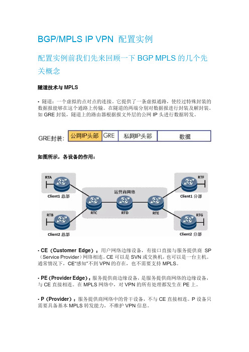
如图所示,各设备的作用:•CE(Customer Edge):用户网络边缘设备,有接口直接与服务提供商SP (Service Provider)网络相连。
CE可以是SVN或交换机,也可以是一台主机。
通常情况下,CE“感知”不到VPN的存在,也不需要支持MPLS。
•PE(Provider Edge):服务提供商边缘设备,是服务提供商网络的边缘设备,与CE直接相连。
在MPLS网络中,对VPN的所有处理都发生在PE上。
•P(Provider):服务提供商网络中的骨干设备,不与CE直接相连。
P设备只需要具备基本MPLS转发能力,不维护VPN信息。
用户设备所在的区域,称为一个站点(Site),站点是指相互之间具备IP连通性的一组IP系统,并且这组IP系统的IP连通性不需通过运营商网络实现。
传统的VPN技术存在一些固有的缺陷,导致客户组网时的很多需求无法得到满足,并且实施比较复杂,MPLS VPN的出现解决了传统VPN技术的固有缺陷——地址空间的重叠问题。
• MPLS是天然的隧道,隧道上的路由器可以根据报文的MPLS头进行报文转发。
VRF(Virtual Routing and Forwarding):虚拟路由及转发,它是一种VPN 路由和转发实例。
• 一台PE 路由器,由于可能同时连接了多个VPN 用户,这些用户(的路由)彼此之间需要相互隔离,那么这时候就用到了VRF,PE 路由器上每一个VPN 都有一个VRF。
PE 路由器除了维护全局IP 路由表之外,还为每个VRF 维护一张独立的IP 路由表,这张路由表称为VRF 路由表。

模块 BGP/MPLS VPN基本原理- -RD、RT的作用
一、教学目标:
了解L3VPN 中RD、RT概念及作用
二、教学重点、难点:
1、RD、RT的区别
2、RD、RT在VPN网络中的实现
三、教学过程设计:
VRF中包含两种属性:RD和RT,BGP/MPLS VPN就是通过这两个属性解决用来解决用户地址复用问题、用来识别不同VPN的路由信息问题。
1、RD:路由标识符(Route Distinguisher)
用来解决用户地址复用问题。
路由标识符(RD)只用于PE和CE路由器之间,用于区别不同VPN的IPv4地址。
入口PE路由器生成了一个路由标识符(RD),并将接收到的CE的IPv4路由转化为VPN-IPv4地址。
出口PE路由器,在将路由通告给CE路由器前,将VPN-IPv4路由转化为IPv4路由。
2、RT:路由目标(route-target)
用来识别不同VPN的路由信息。
RT为路由实例VRF配置输入输出的路由策略,指定PE路由器能够接收、发送哪些路由信息,通过这些路由策略定义VPN的连接性
四、课后作业或思考题:
1、简述L3VPN 中RD、RT概念及作用?
五、本节小结:
对本节内容进行小结。

试验、BGP的基本配置步骤:1、基本的直连配置r1(config)#int lo0r1(config-if)#ip add 1.1.1.1 255.255.255.0r1(config-if)#int s0/0r1(config-if)#ip add 199.99.1.1 255.255.255.0r1(config-if)#no shutr2(config)#int s0/0r2(config-if)#ip add 199.99.1.2 255.255.255.0r2(config-if)#no shutr2(config)#int s0/1r2(config-if)#ip add 199.99.2.1 255.255.255.0r2(config-if)#no shutr3(config)#int s0/0r3(config-if)#ip add 199.99.2.2 255.255.255.0r3(config-if)#no shut2、BGP的配置r1(config)#router bgp 100r1(config-router)#neighbor 199.99.1.2 remote-as 200定义我的bgp邻居,as号是200r2(config)#router bgp 200r2(config-router)#nei 199.99.1.1 remote-as 100r2(config-router)#nei 199.99.2.2 remote-as 200定义我的邻居,AS号是200,跟我的进程一致,说明是IBGPr3(config)#router bgp 200r3(config-router)#nei 199.99.2.1 remote-as 200r1(config)#int lo1r1(config-if)#ip add 10.10.10.10 255.255.255.0r1(config-if)#int lo2r1(config-if)#ip add 110.110.110.110 255.255.255.0第一个宣告我采用的是network标准宣告!!!!r1(config)#router bgp 100r1(config-router)#net 1.1.1.0 mask 255.255.255.0这条路由会进入到bgp的路由表,并且随着bgp的路由传递给下一个ebgp或者ibgp的邻居r1#sh ip bgp 查看bgp的路由表BGP table version is 2, local router ID is 1.1.1.1Status codes: s suppressed, d damped, h history, * valid, > best, i - internal,r RIB-failure, S StaleOrigin codes: i - IGP, e - EGP, ? - incompleteNetwork Next Hop Metric LocPrf Weight Path*> 1.1.1.0/24 0.0.0.0 0 32768 i*=可用的>=最优的Network=宣告的前缀Next Hop=0.0.0.0 自己产生Metric=度量值,直连进来的,当然为0LocPrf =本地优先属性,只在IBGP之间传递Weight=权重属性Path=AS-path路径属性I=起源属性,I代表的是来自IGP的路由我们再来到R1的EBGP对等体邻居来看一下bgp的路由表r2#sh ip bgpBGP table version is 2, local router ID is 199.99.2.1Status codes: s suppressed, d damped, h history, * valid, > best, i - internal,r RIB-failure, S StaleOrigin codes: i - IGP, e - EGP, ? - incompleteNetwork Next Hop Metric LocPrf Weight Path *> 1.1.1.0/24 199.99.1.1 0 0 100 i我们再来R2的IBGP对等体R3来看一下有什么区别?r3#sh ip bgpBGP table version is 1, local router ID is 199.99.2.2Status codes: s suppressed, d damped, h history, * valid, > best, i - internal, r RIB-failure, S StaleOrigin codes: i - IGP, e - EGP, ? - incompleteNetwork Next Hop Metric LocPrf Weight Path * i1.1.1.0/24 199.99.1.1 0 100 0 100 i 没有>,没有最优的路由,??????????????????I=代表的是从IBGP传递过来的,而不是起源属性解决的方法:修改R2到R3的下一跳为自己!!!!!(****)r2(config)#router bgp 200r2(config-router)#nei 199.99.2.2 next-hop-selfr3#sh ip bgpBGP table version is 4, local router ID is 199.99.2.2Status codes: s suppressed, d damped, h history, * valid, > best, i - internal, r RIB-failure, S StaleOrigin codes: i - IGP, e - EGP, ? - incompleteNetwork Next Hop Metric LocPrf Weight Path *>i1.1.1.0/24 199.99.2.1 0 100 0 100 i *>i10.0.0.0 199.99.2.1 0 100 0 100 i *>i110.110.110.0/24 199.99.2.1 0 100 0 100 ?修改后,就正确了!!!r3#sh ip routeCodes: C - connected, S - static, R - RIP, M - mobile, B - BGPD - EIGRP, EX - EIGRP external, O - OSPF, IA - OSPF inter areaN1 - OSPF NSSA external type 1, N2 - OSPF NSSA external type 2E1 - OSPF external type 1, E2 - OSPF external type 2i - IS-IS, su - IS-IS summary, L1 - IS-IS level-1, L2 - IS-IS level-2ia - IS-IS inter area, * - candidate default, U - per-user static routeo - ODR, P - periodic downloaded static routeGateway of last resort is not set1.0.0.0/24 is subnetted, 1 subnetsB 1.1.1.0 [200/0] via 199.99.2.1, 00:00:49110.0.0.0/24 is subnetted, 1 subnetsB 110.110.110.0 [200/0] via 199.99.2.1, 00:00:49C 199.99.2.0/24 is directly connected, Serial0/0B 10.0.0.0/8 [200/0] via 199.99.2.1, 00:00:49下面我们来进行第二个宣告,故意宣告错误,查看结果!!!!!r1(config)#router bgp 100r1(config-router)#net 10.0.0.0 mask 255.0.0.0r1(config)#ip route 10.0.0.0 255.0.0.0 null 0r1#sh ip bgpBGP table version is 3, local router ID is 1.1.1.1Status codes: s suppressed, d damped, h history, * valid, > best, i - internal,r RIB-failure, S StaleOrigin codes: i - IGP, e - EGP, ? - incompleteNetwork Next Hop Metric LocPrf Weight Path*> 1.1.1.0/24 0.0.0.0 0 32768 i*> 10.0.0.0 0.0.0.0 0 32768 i下面我们来进行第三种宣告,利用在发布宣告lo2接口r1(config)#route-map fxh permit 10r1(config-route-map)#match inter lo2抓去接口lo2r1(config-route-map)#exitr1(config)#router bgp 100r1(config-router)#red connr1(config-router)#red connected route-map fxh在发布直连链路,利用route-map做控制,并且进入到bgp的路由r1# sh ip bgpBGP table version is 4, local router ID is 1.1.1.1Status codes: s suppressed, d damped, h history, * valid, > best, i - internal,r RIB-failure, S StaleOrigin codes: i - IGP, e - EGP, ? - incompleteNetwork Next Hop Metric LocPrf Weight Path*> 1.1.1.0/24 0.0.0.0 0 32768 i*> 10.0.0.0 0.0.0.0 0 32768 i*> 110.110.110.0/24 0.0.0.0 0 32768 ??=代表在发布IGP路由进入到BGP中!!!!!3、测试和排错r2#sh ip bgp neighbors 查看BGP的邻居BGP neighbor is 199.99.1.1, remote AS 100, external link(这个是EBGP的邻居)BGP version 4, remote router ID 1.1.1.1(跟ospf的路由ID的意思是一致的)BGP state = Established(一定是这个状态,才代表BGP完全的起来), up for 00:00:50Last read 00:00:20, hold time is 180, keepalive interval is 60 seconds(来检查邻居持续性)Neighbor capabilities:Route refresh: advertised and received(old & new)Address family IPv4 Unicast: advertised and received(MPLS-VPN了)Message statistics:InQ depth is 0OutQ depth is 0Sent RcvdOpens: 1 1Notifications: 0 0Updates: 0 0Keepalives: 2 2Route Refresh: 0 0Total: 3 3Default minimum time between advertisement runs is 30 secondsFor address family: IPv4 UnicastBGP table version 1, neighbor version 0/0Output queue sizes : 0 self, 0 replicatedIndex 1, Offset 0, Mask 0x21 update-group memberSent RcvdPrefix activity: ---- ----Prefixes Current: 0 0Prefixes Total: 0 0Implicit Withdraw: 0 0Explicit Withdraw: 0 0Used as bestpath: n/a 0Used as multipath: n/a 0Outbound InboundLocal Policy Denied Prefixes: -------- -------Total: 0 0Number of NLRIs in the update sent: max 0, min 0Connections established 1; dropped 0Last reset neverConnection state is ESTAB, I/O status: 1, unread input bytes: 0Connection is ECN DisabledLocal host: 199.99.1.2, Local port: 11001Foreign host: 199.99.1.1, Foreign port: 179Enqueued packets for retransmit: 0, input: 0 mis-ordered: 0 (0 bytes)Event Timers (current time is 0x5FCFC):Timer Starts Wakeups NextRetrans 4 0 0x0TimeWait 0 0 0x0AckHold 2 0 0x0SendWnd 0 0 0x0KeepAlive 0 0 0x0GiveUp 0 0 0x0PmtuAger 0 0 0x0DeadWait 0 0 0x0iss: 376417542 snduna: 376417626 sndnxt: 376417626 sndwnd: 16301 irs: 1565270957 rcvnxt: 1565271041 rcvwnd: 16301 delrcvwnd: 83SRTT: 124 ms, RTTO: 1405 ms, RTV: 1281 ms, KRTT: 0 msminRTT: 80 ms, maxRTT: 300 ms, ACK hold: 200 msFlags: active open, nagleIP Precedence value : 6Datagrams (max data segment is 1460 bytes):Rcvd: 5 (out of order: 0), with data: 2, total data bytes: 83Sent: 5 (retransmit: 0, fastretransmit: 0, partialack: 0, Second Congestion: 0), with data:3, total data bytes: 83BGP neighbor is 199.99.2.2, remote AS 200, internal link(说明是IBGP)BGP version 4, remote router ID 199.99.2.2BGP state = Established, up for 00:00:16Last read 00:00:16, hold time is 180, keepalive interval is 60 secondsNeighbor capabilities:Route refresh: advertised and received(old & new)Address family IPv4 Unicast: advertised and receivedMessage statistics:InQ depth is 0OutQ depth is 0Sent RcvdOpens: 1 1Notifications: 0 0Updates: 0 0Keepalives: 1 1Route Refresh: 0 0Total: 2 2Default minimum time between advertisement runs is 5 secondsFor address family: IPv4 UnicastBGP table version 1, neighbor version 0/0Output queue sizes : 0 self, 0 replicatedIndex 2, Offset 0, Mask 0x42 update-group memberSent RcvdPrefix activity: ---- ----Prefixes Current: 0 0Prefixes Total: 0 0Implicit Withdraw: 0 0Explicit Withdraw: 0 0Used as bestpath: n/a 0Used as multipath: n/a 0Outbound Inbound Local Policy Denied Prefixes: -------- -------Total: 0 0Number of NLRIs in the update sent: max 0, min 0Connections established 1; dropped 0Last reset neverConnection state is ESTAB, I/O status: 1, unread input bytes: 0Connection is ECN DisabledLocal host: 199.99.2.1, Local port: 179Foreign host: 199.99.2.2, Foreign port: 11000Enqueued packets for retransmit: 0, input: 0 mis-ordered: 0 (0 bytes)Event Timers (current time is 0x5FF34):Timer Starts Wakeups NextRetrans 2 0 0x0TimeWait 0 0 0x0AckHold 2 1 0x0SendWnd 0 0 0x0KeepAlive 0 0 0x0GiveUp 0 0 0x0PmtuAger 0 0 0x0DeadWait 0 0 0x0iss: 576524820 snduna: 576524885 sndnxt: 576524885 sndwnd: 16320 irs: 1116395438 rcvnxt: 1116395503 rcvwnd: 16320 delrcvwnd: 64SRTT: 70 ms, RTTO: 1683 ms, RTV: 1613 ms, KRTT: 0 msminRTT: 52 ms, maxRTT: 300 ms, ACK hold: 200 msFlags: passive open, nagle, gen tcbsIP Precedence value : 6Datagrams (max data segment is 1460 bytes):Rcvd: 4 (out of order: 0), with data: 2, total data bytes: 64Sent: 3 (retransmit: 0, fastretransmit: 0, partialack: 0, Second Congestion: 0), with data: 1, total data bytes: 64实验:BGP的一些特性还是继续上面的实验!!!!!删除R2和R3的bgp,重新配置r2(config)#no router bgp 200r3(config)#no router bgp 200r2(config)#int lo0r2(config-if)#ip add 2.2.2.2 255.255.255.0r3(config)#int lo0r3(config-if)#ip add 3.3.3.3 255.255.255.0确保两个lo的可达性!!!r2(config)#ip route 3.3.3.0 255.255.255.0 199.99.2.2r3(config)#ip route 2.2.2.0 255.255.255.0 199.99.2.1r2(config)#router bgp 200r2(config-router)#nei 199.99.1.1 remote-as 100r2(config-router)#nei 3.3.3.3 remote-as 200定义我的IBGP邻居r2(config-router)#nei 3.3.3.3 upr2(config-router)#nei 3.3.3.3 update-source lo0定义我的IBGP的邻居的更新源为lo0(重点,这个lo0指的是你自己的lo接口,而不是对方)r3(config)#router bgp 200r3(config-router)#nei 2.2.2.2 remote-as 200r3(config-router)#nei 2.2.2.2 upr3(config-router)#nei 2.2.2.2 update-source lo0r2(config)#router bgp 200r2(config-router)#nei 3.3.3.3 nexr2(config-router)#nei 3.3.3.3 next-hop-S定义邻居3.3.3.3到自己的下一跳是自己。
mplsEnsp试验环境:mpls-bgp.zipR1.txtR1:R2.txtR2:R3.txtR3:R4.txtR4:R5.txtR5:R6.txtR6:R7.txtR7:配置:R1:<R1>display current-configuration#sysname R1#ipvpn-instance site-aipv4-familyroute-distinguisher 10:10vpn-target 1:100 export-extcommunityvpn-target 1:100 import-extcommunity#ipvpn-instance site-bipv4-familyroute-distinguisher 20:20vpn-target 2:200 export-extcommunityvpn-target 2:200 import-extcommunity#mplslsr-id 1.1.1.1mpls#mplsldp##aaaauthentication-scheme defaultauthorization-scheme defaultaccounting-scheme defaultdomain defaultdomaindefault_adminlocal-user admin password cipher OOCM4m($F4ajUn1vMEIBNUw# local-user admin service-type http#firewall zone Local#interface Ethernet0/0/0ip address 12.1.1.1 255.255.255.0mplsmplsldp#interface Ethernet0/0/1ip binding vpn-instance site-aip address 14.1.1.1 255.255.255.0#interface Serial0/0/0link-protocolppp#interface Serial0/0/1link-protocolppp#interface Serial0/0/2link-protocolppp#interface Serial0/0/3link-protocolppp#interface GigabitEthernet0/0/0ip binding vpn-instance site-bip address 13.1.1.1 255.255.255.0#interface GigabitEthernet0/0/1#interface GigabitEthernet0/0/2#interface GigabitEthernet0/0/3#wlan#interface NULL0#interface LoopBack0ip address 1.1.1.1 255.255.255.255#bgp 100peer 3.3.3.3 as-number 100peer 3.3.3.3 connect-interface LoopBack0 #ipv4-family unicastimport-routeospf 2peer 3.3.3.3 enable#ipv4-family vpnv4policyvpn-targetpeer 3.3.3.3 enable#ipv4-familyvpn-instance site-a import-routeospf 2#ipv4-familyvpn-instance site-b import-route directpeer 13.1.1.2 as-number 500#ospf 1area 0.0.0.0network 1.1.1.1 0.0.0.0network 12.1.1.1 0.0.0.0#ospf 2 vpn-instance site-aimport-routebgparea 0.0.0.0network 14.1.1.1 0.0.0.0#user-interface con 0user-interfacevty 0 4user-interfacevty 16 20#ReturnR2:R2>dis current-configuration #sysname R2#mplslsr-id 2.2.2.2mpls#mplsldp##aaaauthentication-scheme default authorization-scheme default accounting-scheme default domain defaultlocal-user admin password cipher OOCM4m($F4ajUn1vMEIBNUw# local-user admin service-type http#firewall zone Localpriority 16#interface Ethernet0/0/0ip address 12.1.1.2 255.255.255.0mplsmplsldp#interface Ethernet0/0/1ip address 23.1.1.1 255.255.255.0mplsmplsldp#interface Serial0/0/0link-protocolppp#interface Serial0/0/1link-protocolppp#interface Serial0/0/2link-protocolppp#interface Serial0/0/3link-protocolppp#interface GigabitEthernet0/0/0#interface GigabitEthernet0/0/1#interface GigabitEthernet0/0/2#interface GigabitEthernet0/0/3#wlan#interface NULL0#interface LoopBack0ip address 2.2.2.2 255.255.255.255#ospf 1network 0.0.0.0 255.255.255.255#user-interface con 0user-interfacevty 0 4user-interfacevty 16 20#ReturnR3:<R3>dis current-configuration#sysname R3#ipvpn-instance site-aipv4-familyroute-distinguisher 10:10vpn-target 1:100 export-extcommunityvpn-target 1:100 import-extcommunity#ipvpn-instance site-bipv4-familyroute-distinguisher 20:20vpn-target 2:200 export-extcommunityvpn-target 2:200 import-extcommunity#mplslsr-id 3.3.3.3mpls#mplsldp##aaaauthentication-scheme defaultauthorization-scheme defaultaccounting-scheme defaultdomain defaultdomaindefault_adminlocal-user admin password cipher F5S!+T-YL&;BH^68NhwORf*# local-user admin service-type http#firewall zone Localpriority 16#interface Ethernet0/0/0ip address 23.1.1.2 255.255.255.0mplsinterface Ethernet0/0/1ip binding vpn-instance site-aip address 25.1.1.1 255.255.255.0#interface Serial0/0/0link-protocolppp#interface Serial0/0/1link-protocolppp#interface Serial0/0/2link-protocolppp#interface Serial0/0/3link-protocolppp#interface GigabitEthernet0/0/0ip binding vpn-instance site-bip address 24.1.1.1 255.255.255.0#interface GigabitEthernet0/0/1#interface GigabitEthernet0/0/2#interface GigabitEthernet0/0/3#wlan#interface NULL0#interface LoopBack3ip address 3.3.3.3 255.255.255.255#bgp 100peer 1.1.1.1 as-number 100peer 1.1.1.1 connect-interface LoopBack3 #ipv4-family unicastundo synchronizationpeer 1.1.1.1 enable#ipv4-family vpnv4policyvpn-targetipv4-familyvpn-instance site-aimport-route rip 1#ipv4-familyvpn-instance site-bimport-route directpeer 24.1.1.2 as-number 700#ospf 1area 0.0.0.0network 0.0.0.0 255.255.255.255network 3.3.3.3 0.0.0.0network 23.1.1.1 0.0.0.0#rip 1 vpn-instance site-aundo summaryversion 2network 25.0.0.0import-routebgp#user-interface con 0user-interfacevty 0 4user-interfacevty 16 20#return<R3>R4:<R4>DIS current-configuration#sysname R4#aaaauthentication-scheme defaultauthorization-scheme defaultaccounting-scheme defaultdomain defaultdomaindefault_adminlocal-user admin password cipher OOCM4m($F4ajUn1vMEIBNUw# local-user admin service-type http#firewall zone Localpriority 16#interface Ethernet0/0/0ip address 14.1.1.2 255.255.255.0#interface Serial0/0/0link-protocolppp#interface Serial0/0/1link-protocolppp#interface Serial0/0/2link-protocolppp#interface Serial0/0/3link-protocolppp#interface GigabitEthernet0/0/0#interface GigabitEthernet0/0/1#interface GigabitEthernet0/0/2#interface GigabitEthernet0/0/3#wlan#interface NULL0#interface LoopBack0ip address 4.4.4.4 255.255.255.255#ospf 2area 0.0.0.0network 0.0.0.0 255.255.255.255#user-interface con 0user-interfacevty 0 4user-interfacevty 16 20#return<R4>R5:<R5>display current-configuration #sysname R5#aaaaccounting-scheme defaultdomain defaultdomaindefault_adminlocal-user admin password cipher OOCM4m($F4ajUn1vMEIBNUw# local-user admin service-type http#firewall zone Localpriority 16#interface Ethernet0/0/0ip address 13.1.1.2 255.255.255.0#interface Ethernet0/0/1#interface Serial0/0/0link-protocolppp#interface Serial0/0/1link-protocolppp#interface Serial0/0/2link-protocolppp#interface Serial0/0/3link-protocolppp#interface GigabitEthernet0/0/0#interface GigabitEthernet0/0/1#interface GigabitEthernet0/0/2#interface GigabitEthernet0/0/3#wlan#interface NULL0#interface LoopBack0ip address 5.5.5.5 255.255.255.255#bgp 500peer 13.1.1.1 as-number 100ipv4-family unicastundo synchronizationnetwork 0.0.0.0network 5.5.5.5 255.255.255.255peer 13.1.1.1 enable#user-interface con 0user-interfacevty 0 4user-interfacevty 16 20#return<R5>R6:<R6>DIS current-configuration#sysname R6#aaaauthentication-scheme defaultauthorization-scheme defaultaccounting-scheme defaultdomain defaultdomaindefault_adminlocal-user admin password cipher OOCM4m($F4ajUn1vMEIBNUw# local-user admin service-type http#firewall zone Localpriority 16#interface Ethernet0/0/0ip address 25.1.1.2 255.255.255.0#interface Ethernet0/0/1#interface Serial0/0/0link-protocolppp#interface Serial0/0/1link-protocolppp#interface Serial0/0/2link-protocolppp#interface Serial0/0/3link-protocolppp#interface GigabitEthernet0/0/0#interface GigabitEthernet0/0/1#interface GigabitEthernet0/0/2#interface GigabitEthernet0/0/3#wlan#interface NULL0#interface LoopBack0ip address 6.6.6.6 255.255.255.255#rip 1undo summaryversion 2network 6.0.0.0network 25.0.0.0#user-interface con 0user-interfacevty 0 4user-interfacevty 16 20#return<R6>R7:<R7>dis current-configuration#sysname R7#aaaauthentication-scheme defaultauthorization-scheme defaultaccounting-scheme defaultdomain defaultdomaindefault_adminlocal-user admin password cipher OOCM4m($F4ajUn1vMEIBNUw# local-user admin service-type http#firewall zone Localpriority 16#interface Ethernet0/0/0ip address 24.1.1.2 255.255.255.0#interface Ethernet0/0/1#interface Serial0/0/0link-protocolppp#interface Serial0/0/1link-protocolppp#interface Serial0/0/2link-protocolppp#interface Serial0/0/3link-protocolppp#interface GigabitEthernet0/0/0#interface GigabitEthernet0/0/1#interface GigabitEthernet0/0/2#interface GigabitEthernet0/0/3#wlan#interface NULL0#interface LoopBack0ip address 7.7.7.7 255.255.255.255 #bgp 700peer 24.1.1.1 as-number 100#ipv4-family unicastundo synchronizationnetwork 7.7.7.7 255.255.255.255 peer 24.1.1.1 enable#user-interface con 0user-interfacevty 0 4user-interfacevty 16 20#return<R7>。