电气外文翻译---电力电子系统的电磁兼容问题
- 格式:docx
- 大小:25.16 KB
- 文档页数:7
电磁兼容与电磁干扰电磁兼容与电磁干扰(Electromagnetic Compatibility and Electromagnetic Interference,简称EMC/EMI)是当今电磁环境下普遍存在的问题。
随着现代电子技术的快速发展,各类电子设备的广泛应用,电磁兼容与电磁干扰问题也日益显著。
本文将就电磁兼容与电磁干扰进行探讨和分析,以期提供一定的理论指导和实践经验。
一、电磁兼容电磁兼容是指在特定的电磁环境下,电子设备能够正常地工作,同时与其它电子设备和环境保持协调。
换句话说,电磁兼容要求电子设备不会由于电磁场的存在而产生损坏或干扰其他设备的工作,同时也不会受到外部电磁干扰的影响。
在实际生产过程中,为了保证电子设备的电磁兼容性,我们需要进行各项测试和分析。
主要包括电磁辐射测试、电磁抗扰度测试、电磁传导干扰测试等。
只有经过这些测试,我们才能够确保设备在各种电磁环境下正常工作。
另外,制定合理的电磁兼容性规范和标准也是非常必要的。
二、电磁干扰电磁干扰是指电磁场对电子设备正常工作的干扰。
一般分为辐射干扰和传导干扰两类。
辐射干扰是指电子设备本身产生的电磁波辐射到周围空间,造成其他设备的工作异常或者产生故障。
为了减少辐射干扰,我们需要对电子设备进行合理设计,采取电磁屏蔽措施,并遵循相关的规范和标准。
传导干扰是指外部电磁场通过传导途径进入设备内部,引起设备的工作异常或产生故障。
为了减少传导干扰,我们可以采取适当的阻抗匹配和屏蔽措施,以降低外部电磁场对设备的影响。
针对电磁干扰问题,我们需要从整个系统的角度进行综合分析和研究,找出可能引起干扰的关键因素,并采取相应的措施进行干扰抑制和干扰消除。
三、电磁兼容与电磁干扰的重要性电磁兼容与电磁干扰的问题不容忽视,其重要性主要体现在以下几个方面:1. 保证电子设备的正常工作。
在日常生活和生产中,我们离不开各式各样的电子设备。
只有保证电子设备能够正常工作,才能够满足人们的需求,推动社会经济的发展。
电力系统中的电磁兼容设计与优化随着电力系统的不断发展和完善,电力设备的数量和种类也越来越多,而这些设备中均存在电磁辐射和电磁干扰的问题。
电磁兼容(Electromagnetic Compatibility,EMC)设计与优化是电力系统中一个重要的方面,它涉及到电磁波的传播、辐射和接收,以及对其他电子设备的干扰和抗干扰能力。
一、电磁兼容的基本概念在电力系统中,电器设备包括发电机、变压器、开关设备、电缆、电动机等,都会通过电磁辐射和电磁干扰与其他设备进行相互作用。
为了保证电力系统的正常工作和其他设备的正常运行,电磁兼容设计就显得尤为重要。
电磁兼容的基本概念是指在电力系统中,各种电磁设备和设施之间相互兼容,互相不对其造成干扰,使电力系统保持良好的电磁环境,并确保电力系统具备良好的抗干扰和抗辐射能力。
具体包括:电磁干扰的抑制、电磁辐射的控制、电磁敏感性的降低以及电磁抗扰能力的提高。
二、电磁兼容设计的原则1. 路由设计原则路由设计是电磁兼容的重要环节。
在电力系统的设计中,应尽量采用合理的电磁兼容路由来布置线路和设备,防止电磁辐射和传导的产生和传播,从而降低对其他设备的干扰和抗扰能力。
2. 接地系统设计原则接地系统是电磁兼容设计的一个重要组成部分。
它主要是为了疏导、消除和减轻设备和系统中产生的电磁干扰,保持合适的接地电位和电压。
因此,接地系统的设计需要合理规划和配置地线、大地电极、接地网等元件,确保接地电阻和接地电位满足要求。
3. 屏蔽设计原则屏蔽设计是电磁兼容设计的重要手段之一,它通过将电子设备和设施置于恰当的屏蔽措施下,以防止电磁辐射的产生和电磁干扰的传播。
屏蔽设计可以采用金属屏蔽、电磁屏蔽罩、屏蔽隔离等方式,提高设备和电路的抗干扰和抗辐射能力。
4. 接线布线设计原则接线布线设计是电磁兼容设计的重要环节,它主要涉及到信号传输线路的布置、电缆的配线和连接方式的选择等。
在接线布线设计中,应遵循路径短、布线整齐、信号线和电源线分隔、避免共模干扰源等原则,减小电磁辐射和传导的产生和传播。
外文资料译文Power Electronics Electromagnetic CompatibilityThe electromagnetic compatibility issues in power electronic systems are essentially the high levels of conducted electromagnetic interference (EMI) noise because of the fast switching actions of the power semiconductor devices. The advent of high-frequency, high-power switching devices resulted in the widespread application of power electronic converters for human productions and livings. The high-power rating and the high-switching frequency of the actions might result in severe conducted EMI. Particularly, with the international and national EMC regulations have become more strictly, modeling and prediction of EMI issues has been an important research topic.By evaluating different methodologies of conducted EMI modeling and prediction for power converter systems includes the following two primary limitations: 1) Due to different applications, some of the existing EMI modeling methods are only valid for specific applications, which results in inadequate generality. 2) Since most EMI studies are based on the qualitative and simplified quantitative models, modeling accuracy of both magnitude and frequency cannot meet the requirement of the full-span EMI quantification studies, which results in worse accuracy. Supported by National Natural Science Foundation of China under Grant 50421703, this dissertation aims to achieve an accurate prediction and a general methodology. Several works including the EMI mechanisms and the EMI quantification computations are developed for power electronic systems. The main contents and originalities in this research can be summarized as follows.I. Investigations on General Circuit Models and EMI Coupling ModesIn order to efficiently analyze and design EMI filter, the conducted EMI noise is traditional decoupled to common-mode (CM) and differential-mode (DM) components. This decoupling is based on the assumption that EMI propagation paths have perfectly balanced and time-invariant circuit structures. In a practical case, power converters usually present inevitable unsymmetrical or time-variant characteristics due to the existence of semiconductor switches. So DM and CM components can not be totally decoupled and they can transform to each other. Therefore, the mode transformation led to another new mode of EMI: mixed-mode EMI. In order to understand fundamental mechanisms by which the mixed-mode EMI noise is excited and coupled, this dissertation proposes the general concept of lumped circuit model for representing the EMI noise mechanism for power electronic converters. The effects of unbalanced noise source impedances on EMI mode transformation are analyzed. The mode transformations between CM and DM components are modeled. The fundamental mechanism of the on-intrinsic EMI is first investigated for a switched mode power supply converter. In discontinuous conduction mode, the DM noise is highly dependent on CM noise because of the unbalanced diode-bridge conduction. It is shown that with the suitable and justifiedmodel, many practical filters pertinent to mixed-mode EMI are investigated, and the noise attenuation can also be derived theoretically. These investigations can provide a guideline for full understanding of the EMI mechanism and accuracy modeling in power electronic converters. (Publications: A new technique for modeling and analysis of mixed-mode conducted EMI noise, IEEE Transactions on Power Electronics, 2004; Study of differential-mode EMI of switching power supplies with rectifier front-end, Transactions of China Electro technical Society, 2006)II. Identification of Essential Coupling Path Models for Conducted EMI Prediction Conducted EMI prediction problem is essentially the problem of EMI noise source modeling and EMI noise propagation path modeling. These modeling methods can be classified into two approaches, mathematics-based method and measurement-based method. The mathematics method is very time-consuming because the circuit models are very complicated. The measurement method is only valid for specific circuit that is conveniently to be measured, and is lack of generality and impracticability. This dissertation proposes a novel modeling concept, called essential coupling path models, derived from a circuit theoretical viewpoint, means that the simplest models contain the dominant noise sources and the dominant noise coupling paths, which can provide a full feature of the EMI generations. Applying the new idea, this work investigates the conducted EMI coupling in an AC/DC half-bridge converter. Three modes of conducted EMI noise are identified by time domain measurements. The lumped circuit models are derived to describe the essential coupling paths based on the identification of the EMI coupling modes. Meanwhile, this study illustrates the extraction of the parameters in the afore-described models by measurements, and demonstrates the significance of each coupling path in producing conducted EMI. It is shown that the proposed method is very effective and accurate in identifying and capturing EMI features. The equivalent models of EMI noise are sorted out by just a few simple measurements. Under these approaches, EMI performance can be predicted together with the filtering strategies. (Publications: Identification of essential coupling path models for conducted EMI prediction in switching power converters, IEEE Transactions on Power Electronics, 2006; Noise source lumped circuit modeling and identification for power converters, IEEE Transactions on Industrial Electronics, 2006)III. High Frequency Conducted EMI Source ModelingThe conventional method of EMI prediction is to model the current or voltage source as a periodic trapezoidal pulse train. However, the single slope approximation for rise and fall transitions can not characterize the real switching transitions involved in high frequency resonances. In most common noise source models simple trapezoidal waveforms are used where the high frequency information of the EMI spectrum is lost. Those models made several important assumptions which greatly impair accuracy in the high frequency range of conducted noise. To achieve reasonable accuracy for EMI modeling at higher frequencies, the relationship between the switching transitions modeling and the EMI spectrum is studied. An important criterion is deduced to give the reasonable modeling frequency range for the traditional simple approximation method. For the first time, an improved and simplified EMI source modeling methodbased on multiple slope approximation of device switching transitions is presented. To confirm the proposed method, a buck circuit prototype using an IGBT module is implemented. Compared with the superimposed envelops of the measured spectra, it can be seen that the effective modeling frequency is extended to more than 10 MHz, which verifies that the proposed multiple slopes switching waveform approximation method can be applied for full-span EMI noise quantification studies. (Publications: Multiple slope switching waveform approximation to improve conducted EMI spectral analysis of power converters, IEEE Transactions on Electromagnetic Compatibility, 2006; Power converter EMI analysis including IGBT nonlinear switching transient model, IEEE Transactions on Industrial Electronics, 2006)IV. Loop Coupling EMI Modeling in Power Electronic SystemsPractical examples of power electronic systems that have various electrical, electromechanical and electronics apparatus emit electromagnetic energy in the course of their normal operations. In order to predict the EMI noise in a system level, it is significant to model the EMI propagation characteristics through electromagnetic coupling between two apparatus circuit within a power electronic system. The PEEC modeling technique which was first introduced in 1970s has recently becomes a popular choice in relation to the electromagnetic analysis and EMI coupling. In previous studies, the integral equation based method was mostly applied in the electrical modeling and analysis of the interconnect structure in very large scale integration systems, only at the electronic chip and package level. By introducing the partial inductance theory of PEEC modeling technique, this work investigates the EMI loop coupling issues in power electronic circuits. The work models the magnetic flux coupling due to EMI current on one conductor and another by mutual inductance. To model the EMI coupling between the grounding circuits, this study divides the ground impedance into two parts: one is the internal impedance and the other is the external inductance. The external inductance due to the fields external to the rectangular grounding loop and flat conductor is modeled. To verify the mathematical models, the steel plane grounding test configurations are constructed and the DM and CM EMI coupling generation and modeling technique are experimentally studied. The comparison between the measured and calculated EMI noise voltage validates the proposed analysis and models. These investigations and results can provide a powerful engineering application of analyzing and solving the coupling EMI issues in power electronic circuits and systems. (This part of work is one of the main contributions of the awarded project of Military Science and Technology Award in 2006, where the author is No. 4 position. Publication: Loop coupled EMI analysis based on partial inductance models, Proceedings of the Chinese Society of Electrical Engineering, 2007)V. Conducted EMI Prediction for PWM Conversion UnitsPWM-based power conversion units are the main EMI noise sources in power systems. Due to the various PWM strategies and the large number of switches, a common analytical approach for the PWM-based switched converter systems has not been dated. Determination of the frequency spectrum of a PWM converter is quite complex and is often done by using an FFT analysis of a simulated time-varyingswitched waveform. This approach requires considerable computing capacity and always leaves the uncertainty as to whether a subtle simulation round-off or error may have slightly tarnished the results obtained. By introducing the principle of the double Fourier integral, this work presents a general method for modeling the conduced EMI sources of PWM conversion units by identifying double integral Fourier form to suit each PWM modulation. Appling the proposed method, three PWM strategies have been discussed. The effects of different modulation schemes on EMI spectrum are evaluated. The EMI modeling and prediction efforts from an industrial application system are studied comprehensively. Comparison between the measured and the predicted spectrum confirms the validity of the EMI modeling and prediction method. This method breaks through the limitations of time-consuming and considerable accumulated error by traditional time-domain simulations. A standard without relying on simulation but a common analytical approach has been obtained. Clearly, it can be regarded as a common analytical approach that would be useful to be able to model and predict the exact EMI performance of the PWM-based power electronic systems. (Publications: DM and CM EMI Sources Modeling for Inverters Considering the PWM Strategies, Transactions of China Electro technical Society, 2007. High Frequency Model of Conducted EMI for PWM Variable-speed Drive Systems, Proceedings of the Chinese Society of Electrical Engineering, 2008)电力电子系统的电磁兼容问题电力电子系统的电磁兼容问题,集中体现为半导体器件的开关工作方式产生的传导性电磁干扰(EMI)。
电力电子系统的EMC问题与解决方案电力电子系统的电磁兼容(Electromagnetic Compatibility,简称EMC)问题是指在电磁环境下,电力电子系统正常工作所需的电磁环境条件,以及电力电子系统对外界电磁环境的产生的电磁干扰的抵抗能力。
在电力电子系统的设计和应用过程中,EMC问题是一个不可避免的挑战。
本文将介绍电力电子系统的EMC问题,并探讨一些解决方案。
一、电力电子系统的EMC问题电力电子系统在运行过程中会产生电磁波,这些电磁波会辐射到周围环境中,对其他设备和系统产生干扰。
同时,电力电子系统也会受到来自外部电磁波的干扰,影响其正常工作。
这些问题都属于电力电子系统的EMC问题。
1. 电磁辐射问题电力电子系统在工作时会产生高频电磁波,如开关电源、变频器和整流器等,这些高频电磁波会通过导线、辐射、波导等途径传播到周围环境中,对其他设备和系统造成干扰。
特别是在无线通信系统和医疗设备等对电磁波敏感的环境中,电磁辐射问题尤为重要。
2. 电磁感受问题电力电子系统对外界电磁波的感受性也是一个重要问题。
当电力电子系统暴露在高强度电磁场的环境中时,会受到来自电磁波的干扰,从而影响其正常工作。
例如,在雷电或强磁场环境下,电力电子系统可能会出现故障或损坏。
二、解决电力电子系统的EMC问题的方案为了解决电力电子系统的EMC问题,需要采取一系列的技术手段和措施。
以下是一些常见的解决方案:1. 地线设计地线是电力电子系统中的重要部分,它能够消除电磁干扰并提高系统的EMC性能。
在地线设计中,需要合理布置和连接地线,建立良好的接地系统,使系统的电磁能量得到合理的分配和消耗,从而减少电磁辐射和提高抗干扰能力。
2. 滤波器设计在电力电子系统中安装滤波器可以有效地减少电磁辐射和抑制电磁干扰。
滤波器能够在电源和负载之间形成一个衰减效应,阻止高频电磁波的传播,从而减少对其他设备的干扰。
3. 接地设计良好的接地设计能够有效地降低电磁辐射和提高系统的抗干扰能力。
电力电子设备电磁兼容性设计引言随着电力电子技术的发展,电力电子设备在能源转换、传输和分配中起着至关重要的作用。
然而,由于电力电子设备中的高频电磁干扰,导致电磁兼容性问题成为一个日益严重的挑战。
本文将探讨电力电子设备的电磁兼容性问题,并介绍一些设计原则和方法来提高电力电子设备的电磁兼容性。
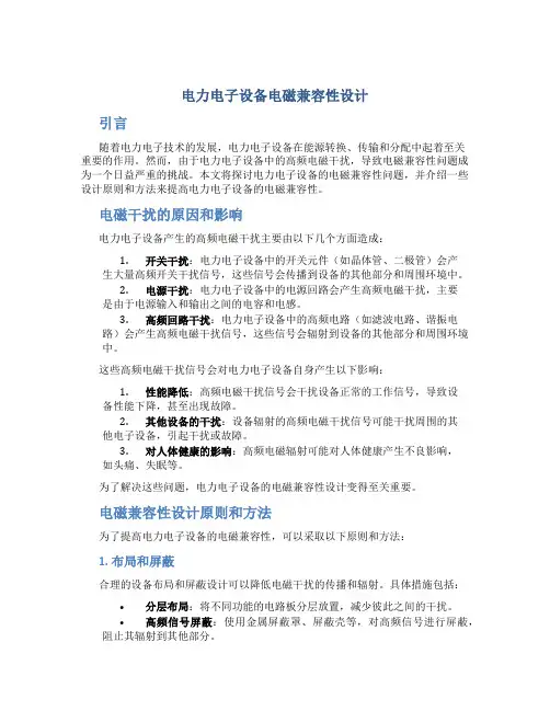
电磁干扰的原因和影响电力电子设备产生的高频电磁干扰主要由以下几个方面造成:1.开关干扰:电力电子设备中的开关元件(如晶体管、二极管)会产生大量高频开关干扰信号,这些信号会传播到设备的其他部分和周围环境中。
2.电源干扰:电力电子设备中的电源回路会产生高频电磁干扰,主要是由于电源输入和输出之间的电容和电感。
3.高频回路干扰:电力电子设备中的高频电路(如滤波电路、谐振电路)会产生高频电磁干扰信号,这些信号会辐射到设备的其他部分和周围环境中。
这些高频电磁干扰信号会对电力电子设备自身产生以下影响:1.性能降低:高频电磁干扰信号会干扰设备正常的工作信号,导致设备性能下降,甚至出现故障。
2.其他设备的干扰:设备辐射的高频电磁干扰信号可能干扰周围的其他电子设备,引起干扰或故障。
3.对人体健康的影响:高频电磁辐射可能对人体健康产生不良影响,如头痛、失眠等。
为了解决这些问题,电力电子设备的电磁兼容性设计变得至关重要。
电磁兼容性设计原则和方法为了提高电力电子设备的电磁兼容性,可以采取以下原则和方法:1. 布局和屏蔽合理的设备布局和屏蔽设计可以降低电磁干扰的传播和辐射。
具体措施包括:•分层布局:将不同功能的电路板分层放置,减少彼此之间的干扰。
•高频信号屏蔽:使用金属屏蔽罩、屏蔽壳等,对高频信号进行屏蔽,阻止其辐射到其他部分。
•地面屏蔽:加强设备的地面屏蔽,减少地面回路干扰。
2. 滤波器设计合理设计滤波器可以减少电力电子设备辐射的高频电磁干扰信号。
滤波器可以包括输入滤波器和输出滤波器。
具体措施包括:•输入滤波器:通过合理设计输入滤波器,可以降低电源干扰信号的传导。
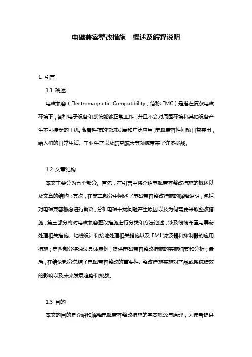
电磁兼容整改措施概述及解释说明1. 引言1.1 概述电磁兼容(Electromagnetic Compatibility,简称EMC)是指在复杂电磁环境下,各种电子设备和系统能够正常工作,并且不会对周围环境和其他设备产生不可接受的干扰。
随着科技的快速发展和广泛应用,电磁兼容性问题日益突出,给人们的日常生活、工业生产以及航空航天等领域带来了许多挑战。
1.2 文章结构本文主要分为五个部分。
首先,在引言中将介绍电磁兼容整改措施的概述以及文章的结构;其次,在第二部分中阐述了电磁兼容整改措施的解释说明,包括对电磁兼容概念进行解释、分析电磁干扰问题产生原因以及为何需要采取整改措施;第三部分将对电磁兼容整改措施进行分类和方法论述,涉及线缆布置与屏蔽处理相关措施、地线设计和接地处理相关措施以及EMI滤波器和抑制器的应用措施;第四部分将通过具体案例,提供电磁兼容整改措施的实施细节和分析;最后,在结论部分总结了电磁兼容整改的重要性、整改措施实施对产品或系统绩效的影响以及未来发展趋势和挑战。
1.3 目的本文的目的是介绍和解释电磁兼容整改措施的基本概念与原理,为读者提供一种了解和应用这些措施的方法。
通过深入理解电磁兼容整改问题,读者可以有效地识别和解决相关问题,并采取相应的措施来确保设备和系统在复杂电磁环境中的正常运行。
2. 电磁兼容整改措施解释说明:2.1 电磁兼容概念解释电磁兼容指的是在电子设备或系统中,各种不同的电子设备能够在不产生互相干扰或受到外界干扰的情况下协同工作的能力。
在现代科技发展中,电子设备越来越复杂,频谱资源日益紧张,因此保持良好的电磁兼容性显得尤为重要。
2.2 电磁干扰问题分析在电子设备中,存在着各种类型的电磁场,包括辐射、传导和导耦等。
这些电磁场可能会对其他附近的设备或系统造成干扰,导致无法正常工作或降低性能。
例如,在无线通信系统中,如果存在强大的脉冲噪声源,则可能会引起接收器敏感度下降或信号质量恶化。
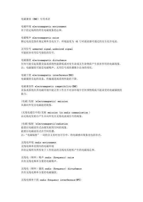
电磁兼容(EMC)专用术语电磁环境 electromagnetic environment在于给定场所的所有电磁现象的总和。
电磁噪声 electromagnetic noise额定电流是指在规定频率及电压下,环境温度为 40 ℃时滤波器可通过的安全允许电流。
无用信号 unwanted signal,undesired signal可能损害有用信号接收的信号。
电磁骚扰 electromagnetic disturbance任何可能引起装置设备或系统性能降低或对有生命或无生命物质产生损害作用的电磁现象。
注:电磁骚扰可能是电磁噪声、无用信号或传播媒介自身的变化。
电磁干扰 electromagnetic interference(EMI)电磁骚扰引起的设备、传输通道或系统性能的下降。
电磁兼容性 electromagnetic compatibility(EMC)设备或系统在其电磁环境中能正常工作且不对该环境中任何事物构成不能承受的电磁骚扰的能力。
(电磁)发射 (electromagnetic) emission从源向外发出电磁能的现象。
(无线电通信中的)发射 emission (in radio communication )由无线电发射台产生并向外发出无线电波或信号的现象。
(电磁)辐射 (electromagnetic)radiation能量以电磁波形式由源发射到空间的现象。
能量以电磁波形式在空间传播。
注:“电磁辐射”一词的含义有时也可引申,将电磁感应现象也包括在内。
无线电环境 radio environment无线电频率范围内的电磁环境在给定场所内所有处于工作状态的无线电发射机产生的电磁场总和。
无线电(频率)噪声 radio (frequency) noise具有无线电频率分量的电磁噪声。
无线电(频率)骚扰 radio (frequency) disturbance具有无线电频率分量的电磁骚扰。
无线电频率干扰 radio frequency interference(RFI)由无线电骚扰引起的有用信号接收性能的下降。
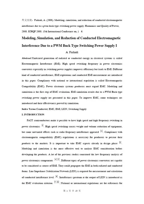
外文出处:Farhadi, A. (2008). Modeling, simulation, and reduction of conducted electromagnetic interference due to a pwm buck type switching power supply. Harmonics and Quality of Power, 2008. ICHQP 2008. 13th International Conference on, 1 - 6.Modeling, Simulation, and Reduction of Conducted Electromagnetic Interference Due to a PWM Buck Type Switching Power Supply IA. FarhadiAbstract:Undesired generation of radiated or conducted energy in electrical systems is called Electromagnetic Interference (EMI). High speed switching frequency in power electronics converters especially in switching power supplies improves efficiency but leads to EMI. Different kind of conducted interference, EMI regulations and conducted EMI measurement are introduced in this paper. Compliancy with national or international regulation is called Electromagnetic Compatibility (EMC). Power electronic systems producers must regard EMC. Modeling and simulation is the first step of EMC evaluation. EMI simulation results due to a PWM Buck type switching power supply are presented in this paper. To improve EMC, some techniques are introduced and their effectiveness proved by simulation.Index Terms:Conducted, EMC, EMI, LISN, Switching SupplyI. INTRODUCTIONFAST semiconductors make it possible to have high speed and high frequency switching in power electronics []1. High speed switching causes weight and volume reduction of equipment, but some unwanted effects such as radio frequency interference appeared []2. Compliance with electromagnetic compatibility (EMC) regulations is necessary for producers to present their products to the markets. It is important to take EMC aspects already in design phase []3. Modeling and simulation is the most effective tool to analyze EMC consideration before developing the products. A lot of the previous studies concerned the low frequency analysis of power electronics components []4[]5. Different types of power electronics converters are capable to be considered as source of EMI. They could propagate the EMI in both radiated and conducted forms. Line Impedance Stabilization Network (LISN) is required for measurement and calculation of conducted interference level []6. Interference spectrum at the output of LISN is introduced as the EMC evaluation criterion []7[]8. National or international regulations are the references forthe evaluation of equipment in point of view of EMC []7[]8.II. SOURCE, PATH AND VICTIM OF EMIUndesired voltage or current is called interference and their cause is called interference source. In this paper a high-speed switching power supply is the source of interference.Interference propagated by radiation in area around of an interference source or by conduction through common cabling or wiring connections. In this study conducted emission is considered only. Equipment such as computers, receivers, amplifiers, industrial controllers, etc that are exposed to interference corruption are called victims. The common connections of elements, source lines and cabling provide paths for conducted noise or interference. Electromagnetic conducted interference has two components as differential mode and common mode []9.A. Differential mode conducted interferenceThis mode is related to the noise that is imposed between different lines of a test circuit by a noise source. Related current path is shown in Fig. 1 []9. The interference source, path impedances, differential mode current and load impedance are also shown in Fig. 1.B. Common mode conducted interferenceCommon mode noise or interference could appear and impose between the lines, cables or connections and common ground. Any leakage current between load and common ground couldbe modeled by interference voltage source.Fig. 2 demonstrates the common mode interference source, common mode currents Iandcm1 and the related current paths[]9.The power electronics converters perform as noise source Icm2between lines of the supply network. In this study differential mode of conducted interference is particularly important and discussion will be continued considering this mode only.III. ELECTROMAGNETIC COMPATIBILITY REGULATIONS Application of electrical equipment especially static power electronic converters in different equipment is increasing more and more. As mentioned before, power electronics converters are considered as an important source of electromagnetic interference and have corrupting effects on the electric networks []2. High level of pollution resulting from various disturbances reduces the quality of power in electric networks. On the other side some residential, commercial and especially medical consumers are so sensitive to power system disturbances including voltage and frequency variations. The best solution to reduce corruption and improve power quality is complying national or international EMC regulations. CISPR, IEC, FCC and VDE are among the most famous organizations from Europe, USA and Germany who are responsible for determining and publishing the most important EMC regulations. IEC and VDE requirement and limitations on conducted emission are shown in Fig. 3 and Fig. 4 []7[]9.For different groups of consumers different classes of regulations could be complied. Class Afor common consumers and class B with more hard limitations for special consumers are separated in Fig. 3 and Fig. 4. Frequency range of limitation is different for IEC and VDE that are 150 kHz up to 30 MHz and 10 kHz up to 30 MHz respectively. Compliance of regulations is evaluated by comparison of measured or calculated conducted interference level in the mentioned frequency range with the stated requirements in regulations. In united European community compliance of regulation is mandatory and products must have certified label to show covering of requirements []8.IV. ELECTROMAGNETIC CONDUCTED INTERFERENCE MEASUREMENTA. Line Impedance Stabilization Network (LISN)1-Providing a low impedance path to transfer power from source to power electronics converter and load.2-Providing a low impedance path from interference source, here power electronics converter, to measurement port.Variation of LISN impedance versus frequency with the mentioned topology is presented inFig. 7. LISN has stabilized impedance in the range of conducted EMI measurement []7.Variation of level of signal at the output of LISN versus frequency is the spectrum of interference. The electromagnetic compatibility of a system can be evaluated by comparison of its interference spectrum with the standard limitations. The level of signal at the output of LISN in frequency range 10 kHz up to 30 MHz or 150 kHz up to 30 MHz is criterion of compatibility and should be under the standard limitations. In practical situations, the LISN output is connected to a spectrum analyzer and interference measurement is carried out. But for modeling and simulation purposes, the LISN output spectrum is calculated using appropriate software.基于压降型PWM开关电源的建模、仿真和减少传导性电磁干扰摘要:电子设备之中杂乱的辐射或者能量叫做电磁干扰(EMI)。
什么是电路的电磁兼容性电路的电磁兼容性(Electromagnetic Compatibility, EMC)是指电子系统或设备在同一环境中同时正常工作、不产生互相干扰的能力。
电磁兼容性问题是电子产品设计与应用中必须重视的因素,关系到电子系统的稳定性、可靠性和安全性。
本文将介绍电路的电磁兼容性的概念、重要性、影响因素以及提高电磁兼容性的方法等内容。
一、电磁兼容性的概念电磁兼容性是指电子设备或系统在电磁环境中不受到不必要的干扰,并不对其他设备和系统造成不必要的干扰的能力。
简单来说,就是电子设备之间能够和谐共存,不产生相互之间的电磁干扰。
二、电磁兼容性的重要性在现代电子设备广泛应用的背景下,电磁兼容性的重要性变得越来越突出。
首先,电磁干扰会导致电子设备性能下降或功能丧失,甚至会引发严重的事故隐患。
其次,电子产品之间的电磁干扰也会扩大到整个电磁环境,对通信系统、无线电接收机、电力系统等造成干扰,影响日常生活秩序。
因此,保证电磁兼容性具有十分重要的意义。
三、影响电磁兼容性的因素3.1 电源线干扰:电源线可能会传导电磁辐射干扰或电磁感应干扰,通过电源线对系统内部或其他系统造成干扰。
3.2 信号线干扰:信号线可能会成为电磁辐射源或电磁感应源,对周围设备或系统产生干扰。
3.3 地线干扰:地线由于在电源线和信号线之间传导电流,可能产生共模干扰,引起系统干扰。
3.4 PCB布线设计:正确的PCB布线设计能够有效降低电磁辐射干扰,减少电磁感应干扰。
3.5 辐射抑制和屏蔽技术:合理的辐射抑制和屏蔽技术对于提高电磁兼容性至关重要。
3.6 设备的抗干扰能力:设备自身抗干扰能力对于提高电磁兼容性也有一定的影响。
四、提高电磁兼容性的方法4.1 合理的电路设计:在电路设计过程中,应充分考虑电磁兼容性,减小电磁辐射和电磁感应。
4.2 优化线路布局:合理的线路布局可以减少电磁辐射和感应,提高电磁兼容性。
4.3 使用滤波器:滤波器可以将干扰信号滤除或降低,改善电磁兼容性。
电工技师技术论文范文浅谈电工技术领域中的电磁兼容摘要随着社会经济的高速发展,电工技术领域也获得了飞速发展,伴随着着巨大的发展,电工技术对电磁环境的要求也更加严格,但由于发展带来的电磁环境问题也逐渐增多,因此,电工技术中的电磁兼容问题成了电工技术领域发展中重要思考的课题。
电磁兼容技术则作为消除电气设备的电磁干扰破坏性影响的技术手段也势必走向更规范、更统一的发展【关键词】电工技术电磁兼容随着社会经济的高速发展,电工技术领域也获得了飞速发展,伴随着着巨大的发展,电工技术对电磁环境的要求也更加严格,但由于发展带来的电磁环境问题也逐渐增多,因此,电工技术中的电磁兼容问题成了电工技术领域发展中重要思考的课题。
1 电磁兼容概述电磁兼容Electromagnetic Compatibility具体指代的是在电气设备运转同时产生的一种电磁环境,并且能够满足电气设备的工作不受影响的一种电磁环境与电气设备兼容的现象。
通俗的来说,电磁兼容就是在电磁干扰状况下的噪声不损害正常的有用信号情况下与之共存。
电磁兼容主要有三种存在形式:电磁信号、电磁噪声和电磁干扰。
总的来说,电磁兼容趋势需要达到两个要求:一方面是电气设备有一定的电磁敏感性,即对环境中的电磁干扰噪声有一定的抗扰功能,另一方面则是电气设备在正常运转过程中对环境的电磁干扰是有限性的,达到一定的峰值便不能再改变。
2 电工技术领域中的电磁兼容现象现代电气设备中的电磁干扰所引起的电气故障属于随机的故障状态,它有一定的不确定性,但是却能够自行恢复原功能的特征。
现主要描述几个电磁兼容对其影响面较广的电工技术。
2.1 电动车随着环境保护的理念不断深入人心,电动车不具有内燃机也不由尾气排放的特点被许多环保人士喜爱,电动车的出现某一程度上对于城市空气质量的改善起了巨大的作用。
但人们往往着重在于其减少空气污染的层面上,没有对电动车对于电磁环境的影响。
美国曾有学者对内燃机其对电磁环境的影响做过实验证明,电磁噪声会伴随着汽车的数量增多呈流线型增加。
电气工程中的电磁兼容规范要求与应对策略电磁兼容(Electromagnetic Compatibility,简称EMC)是电气工程中一个重要的概念。
它涉及到电子设备和系统在同一空间内运行时所产生的电磁干扰和敏感度问题。
为了保证电子设备和系统可以在不产生电磁干扰或受到干扰的情况下正常运行,电磁兼容规范和相应的应对策略显得尤为重要。
一、电磁兼容规范要求电磁兼容规范是指对电子设备和系统的设计、制造、安装和使用过程中的电磁干扰问题进行规范和约束的文件。
这些规范通常是由国际、国家或行业组织制定的,旨在保证设备和系统能够在电磁环境下共存并正常工作。
1. 抗干扰能力要求电磁兼容规范中常对设备的抗干扰能力进行要求。
这一要求主要包括设备的抗辐射干扰(Radiated Disturbance)和抗传导干扰(Conducted Disturbance)能力。
抗辐射干扰是指设备对于电磁波的敏感性,抗传导干扰则是指设备对于传导途径中的电磁干扰的抵抗能力。
2. 发射限值要求为了保证设备在运行时不对其他设备和系统造成干扰,电磁兼容规范中通常会对设备发射的电磁辐射限值进行要求。
这些限值要求设备在指定频段内的发射功率不超过规定的阈值,以免对其他设备造成电磁干扰。
3. 灵敏度要求电磁兼容规范也会对设备的灵敏度进行要求。
设备的灵敏度是指设备受到外界电磁干扰时产生故障的可能性。
规范通常要求设备在一定的电磁干扰下仍能正常运行,以保证设备的可靠性。
二、应对策略为了满足电磁兼容规范的要求,需要采取一系列的应对策略。
1. 设备屏蔽设备屏蔽是指对设备进行设计和制造时,采取一定的屏蔽措施,以减少设备辐射和接收到的外界干扰。
常见的屏蔽措施包括在设备外壳内部涂覆屏蔽材料、使用屏蔽罩或屏蔽壳等。
2. 过滤器的使用过滤器是一种常用的抗干扰措施。
它可以将传导途径中的电磁干扰滤除,以保证设备正常工作。
常见的过滤器包括串联滤波器和并联滤波器等。
3. 接地和接线良好的接地和接线是保证电磁兼容的关键。
电力电子技术中的电磁兼容性设计电磁兼容性设计是电力电子技术中必须关注的一个重要方面。
电力电子设备需要在分布式电源、智能电网、清洁能源和高速列车等应用场景中发挥作用,因此在这些应用场景中需要高度注意电磁兼容性的问题。
在本文中,我们将讨论电力电子技术中的电磁兼容性设计。
1. 什么是电磁兼容性?在我们开始讨论电力电子技术中的电磁兼容性设计之前,让我们首先了解一下什么是电磁兼容性。
电磁兼容性通常是指电子设备在电磁环境中与其他设备、系统或环境进行协调、共存甚至共生存的能力。
简而言之,电磁兼容性是一种能够确保电子设备能正常运行且在电磁环境中不产生外部干扰或承受来自外部的干扰的能力。
2. 电力电子技术中的电磁兼容性电力电子技术中的电磁兼容性设计是确保电力电子设备能够在电磁环境中工作并保持高效性的重要一环。
因为电力电子设备通常在高功率状态下运行,为了确保其不受来自其他设备的干扰以及不会对其他设备或环境造成干扰,必须从设备选型、设计、制造和安装等方面考虑电磁兼容性。
3. 电磁干扰的来源电磁干扰的来源是多方面的,它可以来自电力电子设备自身,也可以来自其他设备或环境。
在电力电子技术中,电磁干扰主要来自以下几个方面:(1) 电源/信号线。
电源和信号线是交流电功率/信号输入和输出的主要途径。
这些线路可以作为天线,发射和接收电磁波信号。
(2) 开关元件。
开关元件的开关动作会产生大量噪声和高频随机变化,从而产生电磁干扰。
(3) 电磁辐射。
所有的电子设备都会产生电磁辐射。
尤其是在高压和高功率设备中,电磁辐射可能会对周围的设备和人产生影响。
4. 电磁兼容性设计的方法电磁兼容性设计是为了确保电力电子设备可以在电磁环境中正常工作而采用的一系列方法和手段。
这些方法和手段包括:(1) 策略性地选择设备。
在电力电子设备设计的起始阶段,选择高品质的设备是非常重要的。
例如,低噪声、低漏磁等特性的元器件可以降低设备的电磁辐射和电磁信噪比。
(2) 开展电磁兼容性分析。
电磁兼容性技术在电子电气系统中的应用随着人类社会科技的不断发展,电子电气系统已经成为了人们日常生产和生活中不可缺少的一部分,但是同时也带来了很多问题,其中之一就是电磁干扰问题。
电子电气系统中的电磁干扰不仅可影响到它自身的正常运行,还会对周围的其他设备和系统产生负面影响。
因此,电磁兼容性(EMC,Electromagnetic Compatibility)技术的应用就显得尤为重要,本文将从电磁兼容性技术的定义、应用、标准等多个方面阐述电磁兼容性技术在电子电气系统中的应用。
1. 电磁兼容性技术的定义电磁兼容性技术,即是指在一个有多种电器设备和系统的环境下,通过降低电磁干扰的程度和电器设备的敏感程度,保证各种设备能够在同一环境中相互协调工作。
简单来说,它是指保证电子电气设备和系统之间互不干扰的一种技术,也是一项非常重要的技术。
2. 在电子电气系统中,电磁兼容性技术的应用非常广泛,包括以下几个方面:(1)汽车电子系统随着人们生活水平的不断提高,对于汽车的安全性、舒适性、可靠性的要求也越来越高,因此汽车电子系统也不断发展和完善。
车载电子系统是由很多模块和器件组成的,这些模块和器件之间的电磁互相作用不可避免地会在整个系统中形成干扰,甚至可能引起系统故障。
因此,在汽车电子系统的设计中,电磁兼容性问题的解决是一个至关重要的问题。
汽车电子系统中应用的电磁兼容性技术,可以有效避免电子设备产生的电磁泄漏对其他设备产生干扰,从而使整个电子系统稳定运行。
(2)无线通信设备随着移动互联网的发展,无线通信设备在现代社会中的地位变得越来越重要。
然而,在无线通信设备的使用过程中,会产生一定干扰,会对其他无线设备及周围通讯设施造成干扰,对通讯设备的稳定性造成影响。
电磁兼容性技术就是在这样的背景下应运而生的,它可以有效的降低无线通信设备产生的电磁干扰和受到的电磁干扰,使无线通信设备正常运行,并保证通信的质量。
(3)家用电器家用电器越来越依赖于低功率电子设备的应用,它们不仅具有稳定的性能,而且还能够满足消费者对安全性、健康等方面的需求。
电路设计中的EMC问题与解决方法导言在电路设计与开发的过程中,电磁兼容性(Electromagnetic Compatibility,简称EMC)问题是一个必须重视的方面。
EMC问题的存在可能导致电子设备间的互相干扰,甚至造成设备的损坏。
因此,了解EMC问题的原因和解决方法对于电路设计师来说至关重要。
EMC问题的原因1. 电磁辐射(Electromagnetic Radiation):当电流在电路中流动时,会产生磁场,这个磁场会在空间中扩散并形成电磁波。
如果电磁波强度较高,就会造成电磁干扰,影响其他电子设备的正常工作。
2. 电磁感应(Electromagnetic Induction):当设备接收到外部电磁波时,其内部的电子元器件可能产生感应电流,从而引起设备的故障或异常。
3. 外部电压(External Voltages):在电路设计过程中,如果没有正确处理设备外部电源供电、地线引入等问题,外部电压可能会导致电磁兼容性问题。
EMC问题的解决方法1. 接地设计(Grounding Design):合理的接地设计能够有效降低电路的电磁辐射以及电磁感应。
在接地设计中,需要注意将设备的接地点与电源的接地点相连,以保证信号的返回路径更加稳定。
2. 滤波设计(Filtering Design):通过在电路中加入滤波电路,可以降低电磁干扰的频率范围,使设备对外界干扰的影响减小。
滤波器的选择和设计需要根据实际情况进行,合理选择滤波器的参数和频率范围。
3. 屏蔽设计(Shielding Design):通过在电路设计中添加屏蔽罩或屏蔽材料,可以阻挡或吸收外界的电磁波,减少电磁干扰。
在屏蔽设计中,需要注意材料的选择和屏蔽罩的结构设计,以提高屏蔽效果。
4. 引线布局(Routing Layout):电路引线的布局和走线方式也会对电磁兼容性产生影响。
合理布局电路引线,减小引线之间的交叉和谐振现象,可以有效减少电磁辐射和电磁感应。
电路中的电磁兼容性与抗干扰设计电磁兼容性(Electromagnetic Compatibility,简称EMC)与抗干扰设计在电路领域中起着至关重要的作用。
电磁兼容性指的是电子设备在工作状态下,能够和其他电子设备以及电磁环境相互协调工作,而不会产生互相干扰或者被干扰的现象。
抗干扰设计则是指在电路设计过程中采取一系列措施,以降低设备受到外界电磁干扰的能力以及设备对其他电子设备造成的干扰。
一、电磁兼容性原理电磁兼容性的实现需要考虑两个方面,即电磁辐射和电磁敏感性。
电磁辐射是指设备在工作时所产生的电磁波通过空间传播,可能对周围的设备产生干扰。
电磁敏感性则是指设备对来自其他设备或者外界电磁场的干扰信号产生的相应。
要保证设备的兼容性,需要在设计过程中考虑这两个方面。
为了满足电磁兼容性的要求,设计师需要进行以下工作:1. 电磁辐射控制:通过合理布局,减少电路中的回路面积,降低电流回路的长度,采用屏蔽技术等方法,控制电磁辐射功率的大小,使其在国际标准规定的范围内。
2. 电磁敏感性控制:通过合理设计,采用屏蔽技术,减少设备对来自外界电磁场的敏感度,降低设备对干扰信号的响应。
3. 地线布局:良好的地线布局能够减少地线串扰,提高系统的抗干扰能力。
这包括合理的地线引出方法,减少地线共振等。
4. 滤波器的应用:在电路中加入滤波器能够减少电源线上的高频干扰,并降低设备的辐射噪声。
5. 屏蔽的使用:采用金属盖、金属屏蔽壳等方法,将设备的敏感部分与外界隔离,减少干扰的传播。
二、抗干扰设计的实施1. 设备的框架结构设计:在设备的设计中,应该合理布局各个电路部分,避免电路之间的相互干扰。
对于敏感部分应该采取隔离措施。
2. 电源线设计:电源线是设备中一个重要的噪声源,合理的电源线设计可以有效降低干扰对设备造成的影响。
包括电源线的滤波、地线的设计等。
3. 地线设计:地线是保证设备安全运行的重要组成部分,合理的地线设计可以降低设备对外部干扰的敏感性,防止干扰信号进入设备。
电磁兼容(EMC)基础知识本文思维导图:01EMC(Electro Magnetic Compatibility,电磁兼容)是指电子、电气设备或系统在预期的电磁环境中,不会因为周边的电磁环境而导致性能降低、功能丧失或损坏,也不会在周边环境中产生过量的电磁能量,以致影响周边设备的正常工作。
EMI(Electro Magnetic Interference,电磁干扰):自身产生的电磁干扰不能超过一定的限值。
EMS(Electro Magnetic Susceptibility,电磁抗扰度):自身承受的电磁干扰在一定的范围内。
电磁环境:同种类的产品,不同的环境就有着不同的标准。
需要说明的是,以上都基于一个前提:一定环境里,设备或系统都在正常运行下。
02电磁干扰的产生原因:电压/电流的变化中不必要的部分。
电磁干扰的耦合途径有两种:导线传导和空间辐射。
导线传导干扰原因是电流总是走“最小阻抗”路径。
以屏蔽线为例,低频(f<1kHz)时,导线的电阻起到主要作用,大部分电流从导线的铜线中流过;高频(f>10kHz)时,环路屏蔽层的感抗小于导线的阻抗,因此信号电流从屏蔽层上流过。
干扰电流在导线上传输有两种方式:共模和差模。
一般有用的信号为差模信号,因此共模电流只有转变为差模电流才能对有用信号产生干扰。
阻抗平衡防止共模电流向差模转变,可以通过多点接地用来降低地线公共阻抗,减小共地线阻抗干扰。
空间辐射干扰分近场和远场。
近场又称为感应场,与场源的性质密切相关。
当场源为高电压小电流时,主要表现为电场;当场源为低电压大电流时,主要表现为磁场。
无论是电场还是磁场,当距离大于λ/2π时都变成了远场。
远场又称为辐射场。
远场属于平面波,容易分析和测量,而近场存在电场和磁场的相互转换问题,比较复杂。
这里面有问题的是如果导线变成天线,有时候就分不清是传导干扰还是辐射干扰?低频带下特别是30 MHz以下的主要是传导干扰。
或者可以估算当设备和导线的长度比波长短时,主要问题是传导干扰,当它们的尺寸比波长长时,主要问题是辐射干扰。
电力系统中的电磁兼容性问题与对策实习报告大家好,今天我要给大家分享一下我在实习过程中发现的电力系统中的电磁兼容性问题,以及我们可以采取的一些对策。
我们要知道什么是电磁兼容性。
简单来说,就是在一定的电磁环境中,各种电子设备之间不会互相干扰,能够正常工作。
那么,电力系统中的电磁兼容性问题到底有哪些呢?接下来,我将从三个方面给大家详细讲解。
1.1 电力系统的基本组成在介绍电磁兼容性问题之前,我们先来了解一下电力系统的基本组成。
电力系统主要由发电、输电、配电和用电四个部分组成。
发电部分包括火力发电厂、水力发电厂和核能发电厂等;输电部分主要是通过高压电线将电能从发电厂输送到各地;配电部分则是将输电网中的电能分配给各个用户;用电部分则是用户通过家庭用电设备使用电能。
1.2 电磁兼容性问题的危害电力系统中的电磁兼容性问题可能会导致以下几种危害:一是影响电力设备的正常运行,如发电机、变压器等设备可能会因为电磁干扰而损坏;二是影响电力系统的稳定性,如输电线路上的电磁干扰可能导致输电线路跳闸;三是影响用户的用电安全,如配电设备上的电磁干扰可能导致用户家里的电器出现故障。
2.1 电力系统电磁兼容性问题的来源电力系统中的电磁兼容性问题主要来源于以下几个方面:一是电力设备本身的设计问题,如设备的线圈、铁芯等部件可能产生电磁波;二是输电线路的设计问题,如线路上的感应电压可能导致电磁干扰;三是配电设备的设计问题,如设备的开关、继电器等部件可能产生电磁波;四是用户的用电设备设计问题,如家用电器、照明设备等可能产生电磁波。
2.2 解决电力系统电磁兼容性问题的对策针对以上提到的电力系统中的电磁兼容性问题,我们可以采取以下几种对策:一是加强电力设备的设计,采用低辐射、低噪音的材料和技术,减少设备的电磁波产生;二是优化输电线路的设计,采用屏蔽线缆、避雷针等措施,减少线路上的感应电压;三是改进配电设备的设计,采用无刷电机、变频器等技术,减少设备的电磁波产生;四是提高用户的用电设备设计水平,选择低辐射、低噪音的电器产品。
外文资料译文Power Electronics Electromagnetic CompatibilityThe electromagnetic compatibility issues in power electronic systems are essentially the high levels of conducted electromagnetic interference (EMI) noise because of the fast switching actions of the power semiconductor devices. The advent of high-frequency, high-power switching devices resulted in the widespread application of power electronic converters for human productions and livings. The high-power rating and the high-switching frequency of the actions might result in severe conducted EMI. Particularly, with the international and national EMC regulations have become more strictly, modeling and prediction of EMI issues has been an important research topic.By evaluating different methodologies of conducted EMI modeling and prediction for power converter systems includes the following two primary limitations: 1) Due to different applications, some of the existing EMI modeling methods are only valid for specific applications, which results in inadequate generality. 2) Since most EMI studies are based on the qualitative and simplified quantitative models, modeling accuracy of both magnitude and frequency cannot meet the requirement of the full-span EMI quantification studies, which results in worse accuracy. Supported by National Natural Science Foundation of China under Grant 50421703, this dissertation aims to achieve an accurate prediction and a general methodology. Several works including the EMI mechanisms and the EMI quantification computations are developed for power electronic systems. The main contents and originalities in this research can be summarized as follows.I. Investigations on General Circuit Models and EMI Coupling ModesIn order to efficiently analyze and design EMI filter, the conducted EMI noise is traditional decoupled to common-mode (CM) and differential-mode (DM) components. This decoupling is based on the assumption that EMI propagation paths have perfectly balanced and time-invariant circuit structures. In a practical case, power converters usually present inevitable unsymmetrical or time-variant characteristics due to the existence of semiconductor switches. So DM and CM components can not be totally decoupled and they can transform to each other. Therefore, the mode transformation led to another new mode of EMI: mixed-mode EMI. In order to understand fundamental mechanisms by which the mixed-mode EMI noise is excited and coupled, this dissertation proposes the general concept of lumped circuit model for representing the EMI noise mechanism for power electronic converters. The effects of unbalanced noise source impedances on EMI mode transformation are analyzed. The mode transformations between CM and DM components are modeled. The fundamental mechanism of the on-intrinsic EMI is first investigated for a switched mode power supply converter. In discontinuousconduction mode, the DM noise is highly dependent on CM noise because of the unbalanced diode-bridge conduction. It is shown that with the suitable and justified model, many practical filters pertinent to mixed-mode EMI are investigated, and the noise attenuation can also be derived theoretically. These investigations can provide a guideline for full understanding of the EMI mechanism and accuracy modeling in power electronic converters. (Publications: A new technique for modeling and analysis of mixed-mode conducted EMI noise, IEEE Transactions on Power Electronics, 2004; Study of differential-mode EMI of switching power supplies with rectifier front-end, Transactions of China Electrotechnical Society, 2006)II. Identification of Essential Coupling Path Models for Conducted EMI Prediction Conducted EMI prediction problem is essentially the problem of EMI noise source modeling and EMI noise propagation path modeling. These modeling methods can be classified into two approaches, mathematics-based method and measurement-based method. The mathematics method is very time-consuming because the circuit models are very complicated. The measurement method is only valid for specific circuit that is conveniently to be measured, and is lack of generality and impracticability. This dissertation proposes a novel modeling concept, called essential coupling path models, derived from a circuit theoretical viewpoint, means that the simplest models contain the dominant noise sources and the dominant noise coupling paths, which can provide a full feature of the EMI generations. Applying the new idea, this work investigates the conducted EMI coupling in an AC/DC half-bridge converter. Three modes of conducted EMI noise are identified by time domain measurements. The lumped circuit models are derived to describe the essential coupling paths based on the identification of the EMI coupling modes. Meanwhile, this study illustrates the extraction of the parameters in the afore-described models by measurements, and demonstrates the significance of each coupling path in producing conducted EMI. It is shown that the proposed method is very effective and accurate in identifying and capturing EMI features. The equivalent models of EMI noise are sorted out by just a few simple measurements. Under these approaches, EMI performance can be predicted together with the filtering strategies. (Publications: Identification of essential coupling path models for conducted EMI prediction in switching power converters, IEEE Transactions on Power Electronics, 2006; Noise source lumped circuit modeling and identification for power converters, IEEE Transactions on Industrial Electronics, 2006)III. High Frequency Conducted EMI Source ModelingThe conventional method of EMI prediction is to model the current or voltage source as a periodic trapezoidal pulse train. However, the single slope approximation for rise and fall transitions can not characterize the real switching transitions involved in high frequency resonances. In most common noise source models simple trapezoidal waveforms are used where the high frequency information of the EMI spectrum is lost. Those models made several important assumptions which greatly impair accuracy in the high frequency range of conducted noise. To achieve reasonable accuracy for EMI modeling at higher frequencies, the relationship between the switching transitions modeling and the EMI spectrum is studied. An important criterion is deduced to givethe reasonable modeling frequency range for the traditional simple approximation method. For the first time, an improved and simplified EMI source modeling method based on multiple slope approximation of device switching transitions is presented. To confirm the proposed method, a buck circuit prototype using an IGBT module is implemented. Compared with the superimposed envelops of the measured spectra, it can be seen that the effective modeling frequency is extended to more than 10 MHz, which verifies that the proposed multiple slopes switching waveform approximation method can be applied for full-span EMI noise quantification studies. (Publications: Multiple slope switching waveform approximation to improve conducted EMI spectral analysis of power converters, IEEE Transactions on Electromagnetic Compatibility, 2006; Power converter EMI analysis including IGBT nonlinear switching transient model, IEEE Transactions on Industrial Electronics, 2006)IV. Loop Coupling EMI Modeling in Power Electronic SystemsPractical examples of power electronic systems that have various electrical, electromechanical and electronics apparatus emit electromagnetic energy in the course of their normal operations. In order to predict the EMI noise in a system level, it is significant to model the EMI propagation characteristics through electromagnetic coupling between two apparatus circuit within a power electronic system. The PEEC modeling technique which was first introduced in 1970s has recently becomes a popular choice in relation to the electromagnetic analysis and EMI coupling. In previous studies, the integral equation based method was mostly applied in the electrical modeling and analysis of the interconnect structure in very large scale integration systems, only at the electronic chip and package level. By introducing the partial inductance theory of PEEC modeling technique, this work investigates the EMI loop coupling issues in power electronic circuits. The work models the magnetic flux coupling due to EMI current on one conductor and another by mutual inductance. To model the EMI coupling between the grounding circuits, this study divides the ground impedance into two parts: one is the internal impedance and the other is the external inductance. The external inductance due to the fields external to the rectangular grounding loop and flat conductor is modeled. To verify the mathematical models, the steel plane grounding test configurations are constructed and the DM and CM EMI coupling generation and modeling technique are experimentally studied. The comparison between the measured and calculated EMI noise voltage validates the proposed analysis and models. These investigations and results can provide a powerful engineering application of analyzing and solving the coupling EMI issues in power electronic circuits and systems. (This part of work is one of the main contributions of the awarded project of Military Science and Technology Award in 2006, where the author is No. 4 position. Publication: Loop coupled EMI analysis based on partial inductance models, Proceedings of the Chinese Society of Electrical Engineering, 2007)V. Conducted EMI Prediction for PWM Conversion UnitsPWM-based power conversion units are the main EMI noise sources in power systems. Due to the various PWM strategies and the large number of switches, a common analytical approach for the PWM-based switched converter systems has notbeen dated. Determination of the frequency spectrum of a PWM converter is quite complex and is often done by using an FFT analysis of a simulated time-varying switched waveform. This approach requires considerable computing capacity and always leaves the uncertainty as to whether a subtle simulation round-off or error may have slightly tarnished the results obtained. By introducing the principle of the double Fourier integral, this work presents a general method for modeling the conduced EMI sources of PWM conversion units by identifying double integral Fourier form to suit each PWM modulation. Appling the proposed method, three PWM strategies have been discussed. The effects of different modulation schemes on EMI spectrum are evaluated. The EMI modeling and prediction efforts from an industrial application system are studied comprehensively. Comparison between the measured and the predicted spectrum confirms the validity of the EMI modeling and prediction method. This method breaks through the limitations of time-consuming and considerable accumulated error by traditional time-domain simulations. A standard without relying on simulation but a common analytical approach has been obtained. Clearly, it can be regarded as a common analytical approach that would be useful to be able to model and predict the exact EMI performance of the PWM-based power electronic systems. (Publications: DM and CM EMI Sources Modeling for Inverters Considering the PWM Strategies, Transactions of China Electrotechnical Society, 2007. High Frequency Model of Conducted EMI for PWM Variable-speed Drive Systems, Proceedings of the Chinese Society of Electrical Engineering, 2008)电力电子系统的电磁兼容问题电力电子系统的电磁兼容问题,集中体现为半导体器件的开关工作方式产生的传导性电磁干扰(EMI)。