毕业设计外文原文+翻译(电力系统)
- 格式:docx
- 大小:1.00 MB
- 文档页数:16
Section 1 Introduction 第一节介绍The modern society depends on the electricity supply more heavily than ever before.现代社会比以往任何时候对电力供应的依赖更多。
It can not be imagined what the world should be if the electricity supply were interrupted all over the world. 如果中断了世界各地的电力供应,无法想像世界会变成什么样子Electric power systems (or electric energy systems), providing electricity to the modern society, have become indispensable components of the industrial world. 电力系统(或电力能源系统),提供电力到现代社会,已成为产业界的不可缺少的组成部分。
The first complete electric power system (comprising a generator, cable, fuse, meter, and loads) was built by Thomas Edison –the historic Pearl Street Station in New York City which began operation in September 1882. 托马斯爱迪生建立了世界上第一个完整的电力系统(包括发电机,电缆,熔断器,计量,并加载)它就是位于纽约市具有历史意义的珍珠街的发电厂始于1882年9月运作。
This was a DC system consisting of a steam-engine-driven DC generator supplying power to 59 customers within an area roughly 1.5 km in radius. The load, which consisted entirely of incandescent lamps, was supplied at 110 V through an underground cable system. 这是一个直流系统,由一个蒸汽发动机驱动的直流发电机其供电面积约1.5公里至59范围内的客户。
英文原文:Power system communication power supply test and maintenance ofthe battery solutionAbstractIn a large number of data experiments and field application, and on the basis of the telecom room in the power the power of common common problems are analyzed and discussed, from, testing and maintenance of real-time monitoring system safety, and put forward a set of complete solutions.Keywords: battery group; Power source; Detection; maintenanceIntroductionThe electric power communication system center room equipped with a large amount of storage battery installation, on the communications department.The operation of the electric power systems and support, spare play an important role. But in the maintenance process, or will often meet many problems, a detailed analysis of the below.1. The battery power supply condition and analyzes the reasonsWe for large communication machine. Room on the actual test, to the battery power supply system for the comprehensive study, found that many rooms, communications equipment have low load capacity battery, system reliability of the poor, in here are two groups of data about battery problems:A. battery service life for the design of the general 8-1 O years, and statistical data show that the battery life ideal circumstances can achieve 4-6 years, generally can not meet the design demand, a large number of telecommunication room used less than 3 years (some two years) appear behind battery, part of the battery even scrapped;B. 2010 years urumqi power bureau telecommunication room data show that because the battery electric power communication power supply fault from accidents accounted for 35%, in recent years the data interface rapidly, the ratio has risen to 7%.Two sets of data to show that the problem is more serious battery, the battery power supply of security and reliability have a serious threat, investigate its reason, mainly in the following nine aspects:1.1 battery design process qualityThe battery design process exists plate technology design, material design, oxygen composite design, the pressure setA comprehensive plan defect, make a battery performance and life have been affected, main performance for battery failure, early leakage water loss, deformation cracks, etc.For simple ascending battery capacity, will the battery plate thin, and increase the number plate, makes the same volume of the casing electrolyte reaction area greatly increased, capacity improve soon, but because thin plate, plate easily corrosion, softening battery, service life and therefore greatly shorten, easy to produce the early failure problems.Because of the low pressure setting, charge once to a certain pressure, control valves will be openRev., gas is through the valve were leaked, cause the battery fluid loss (usually in a hole or a column valve will find a slightly damp near the liquid), this kind of battery also easy to produce the early failure, valve pressure design and material also has a direct relationship between the shell.Due to shell material, oxygen composite efficiency, valve design pressure, and other comprehensive technology lack, some batteries in the process of charging and discharging pool, easy to produce the shell deformation, beat even crack.1.2 the influence of the operation environmentRunning environment is the main room temperature on battery life influence is bigger, in 25 ℃environment conditions, the environmental average temperature increase every 10 ℃, battery life is reduced by half. Northwest temperature changes greatly (a 30 ℃a + 55 ~ C), the substation telecommunication room less equipped with air conditioner, thermal performance is poor, temperature on battery life form directly influence.1.3 operation mode and installation methodBattery packs are generally more battery series into a group, two groups of parallel operation. Site oftenFound in the internal battery, article connection (board) corner of battery performance generally have slightly worse, the main reason is the article connection too long (other connection is the article 5 a l0 times) and the materials of the contact resistance caused too large, lead to the connection of pressure drop article is too big, in the process of charging and discharging, will seriously affect peripheral battery charging and discharging effect, this kind of problem should be avoided.1.4 the quality of power supply and load design problemThe telecom room is located in remote general transformer substation, often without power and the battery in frequent charged, and discharge status, the serious influence battery life. Computer room load relative to the battery capacity are slants small, such as the actual load for 30 A, communications equipment configuration of battery capacity is commonly two groups of 300 Ah, the utility after interrupting, storage battery will to tiny current began to discharge, and small discharge current generation of sulfuric acid lead particles is easy to crystallization into pieces and E telecommunication room are generally rural power supply, the quality of power supply is not stable, power over A long period of time, power outages frequent, sulfuric acid lead particles generated more easily irreversible sulfate.1.5 professional testing methods and lack of equipmentIn the discharge detection, due to lack of monomer detection equipment protection functions, therefore, in discharge only by the group when voltageobservation, combined with manual measuring for inspection. Find a 1.8 v battery, immediately suspend test. This way low efficiency, safety all the sex differences, to the battery can't form an effective protection.The battery characteristic parameters are mainly embodied in the voltage, resistance and capacity, the conventional detection method mainly measuring voltage, observe the shell signs, check the bolt tightness etc. So that only some representations to the parameter, and cannot master's important! Parameters such as resistance, capacity, etc.1.6 charger, discharge management system is not perfectRecharging problems mainly involves to charge cycle, all are charging pressure, flow, all are charging filling time,All filling conversion control, float temperature compensation of detailed regulations.Some maintenance personnel to improve battery charging efficiency, improved charging voltage, and increase the charging current, leading to increased pressure, then combined low efficiency, the battery to dehydrate, are plate bar corrosion. With this several years of battery management know deeply, related problems reduce gradually, but for this problem or must cause enough attention to main pay attention to the following three points: one is the charge can't charge high pressure, even with are charging, voltage must also be restricted in 2.35 V scope (the new battery should be controlled in 2-3 V); 2 it is charging electric current cannot too much, it will speed up plates corrosion, cause plate softening, restrain oxygen composite efficiency; 3 it is charging process must be temperature compensation, compensation coefficients for a 3 mV / ℃2 mV / ~ C one.2. Testing and maintenance program2.1 replacement has serious degradation the battery packs, strengthen the selection of the batteryTo find Bi can have depth degradation and a serious threat to the security of the battery power supply systemGroups should be early change, and strengthen the battery technology selection. Process quality problem is the focus of the selection consider battery, the battery can be based on standard, battery makers to raise specific technical requirements, such as of the materials, valve pressure., plate thickness, quantity, voltage, resistance Sui, balanced equilibrium characteristics, oxygen composite efficiency, water loss rate, for through the acceptance test can detect project, must conduct test on these work can be further ensure the reliability of the battery for long-term use.Vrla batteries for production technology is strict, at present domestic battery lifeManufacturers in the more than 300, all sorts of technology of handicraft is various, the proposal is in before purchase, the battery rigorous screening, as far as possible choice complete production equipment, strong technical force, service facilities, perfect brand enterprise. ,2.2 strengthen early battery test, improve battery support ability of put into operationAt the beginning of the storage battery check is a very important testing link, the battery technology standardsIn early to check the battery has a clear request, the engine room of the electric power communication battery installation, run and maintenance and management is of important significance. For the specific requirements of the early battery check is: batteries before put into operation, the first first check sex discharge, its capacity should be not less than 95%, after the completion of the discharge to the battery charge; Filled, a quiet place 1-2 h, make a second check sex discharge, after the completion of the discharge of battery charge; Filled, a quiet place 1 ~ 2 h, third check Bi discharge, its capacity should be not less than 100%, after the completion of the discharge to charge the battery.2.3 maintenance change ideas, strengthen the battery power supply of professional monitoring managementProfessional centralized monitoring system in the traditional monitoring system based on the function, increase the storage of electricityPool monomer battery voltage, resistance and check test functions, the more the earth played a monitoring management functions, improve the maintenance efficiency.Implementing specialized monitoring, and other installation common monitoring or not pack monitoring communications equipment phaseThan, the power supply rate reduced greatly, found that the problem is timely, ensure the safety and reliability of the telecom room improved.2.4 configuration diesel generators, strengthen intelligent control management, ensure that electric power communication securityThe battery electric power communication communications equipment is necessary short time dc power, and diesel generatorMachine is long time plays the role of communication standby power. Most of the communications are no spare room woodOil generator, can increase the small diesel generator configuration.Considering the maintenance workload is big, shortage of personnel, vehicles and equipment and turnover nervous the actual problem, can not intelligent diesel generator increase intelligent control system, in the utility power lost, the utility is unstable, the phase lack, owe pressure, pressure and so on many kinds of conditions, can be automatically start diesel generator, and to switch into power network operation.For the operation of the diesel generator maintenance and management, should also together with battery, into the professional centralized monitoring system, so that in time control system of power the battery operation parameters and working state.中文翻译:电力系统通信蓄电池电源的检测与维护解决方案摘要在大量的数据实验和现场应用的基础上,针对电力通信机房电源普遍存在的共同性问题进行了分析和探讨,从检测维护、实时监控及系统安全等角度提出了一套完整方案。
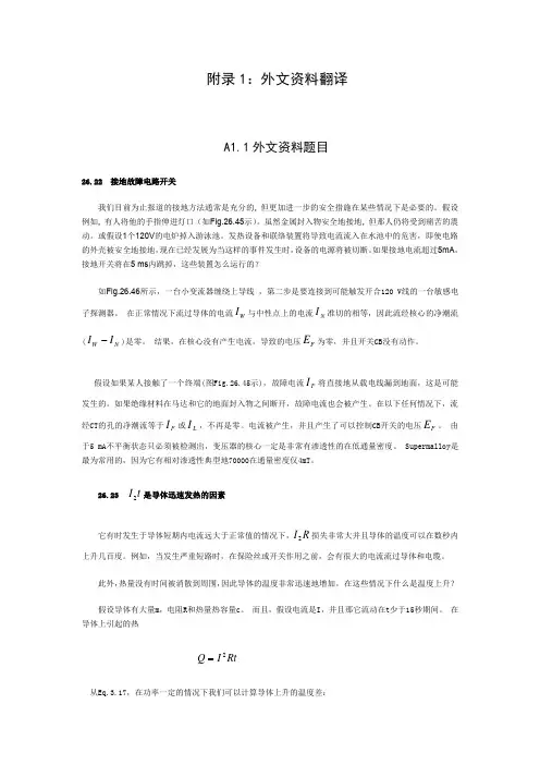
附录1:外文资料翻译A1.1外文资料题目26.22 接地故障电路开关我们目前为止报道的接地方法通常是充分的, 但更加进一步的安全措施在某些情况下是必要的。
假设例如, 有人将他的手指伸进灯口(如Fig.26.45示)。
虽然金属封入物安全地接地, 但那人仍将受到痛苦的震动。
或假设1个120V 的电炉掉入游泳池。
发热设备和联络装置将导致电流流入在水池中的危害,即使电路的外壳被安全地接地,现在已经发展为当这样的事件发生时,设备的电源将被切断。
如果接地电流超过5mA ,接地开关将在5 ms 内跳掉,这些装置怎么运行的?如Fig.26.46所示,一台小变流器缠绕上导线 ,第二步是要连接到可能触发开合120 V 线的一台敏感电子探测器。
在正常情况下流过导体的电流W I 与中性点上的电流N I 准切的相等,因此流经核心的净潮流(N W I I -)是零。
结果,在核心没有产生电流,导致的电压F E 为零,并且开关CB 没有动作。
假设如果某人接触了一个终端(图Fig.26.45示),故障电流F I 将直接地从载电线漏到地面,这是可能发生的。
如果绝缘材料在马达和它的地面封入物之间断开,故障电流也会被产生。
在以下任何情况下,流经CT 的孔的净潮流等于F I 或L I ,不再是零。
电流被产生,并且产生了可以控制CB 开关的电压F E 。
由于5 mA 不平衡状态只必须被检测出,变压器的核心一定是非常有渗透性的在低通量密度。
Supermalloy 是最为常用的,因为它有相对渗透性典型地70000在通量密度仅4mT 。
26.23 t I 2是导体迅速发热的因素它有时发生于导体短期内电流远大于正常值的情况下,R I 2损失非常大并且导体的温度可以在数秒内上升几百度。
例如,当发生严重短路时,在保险丝或开关作用之前,会有很大的电流流过导体和电缆。
此外,热量没有时间被消散到周围,因此导体的温度非常迅速地增加。
在这些情况下什么是温度上升? 假设导体有大量m ,电阻R 和热量热容量c 。
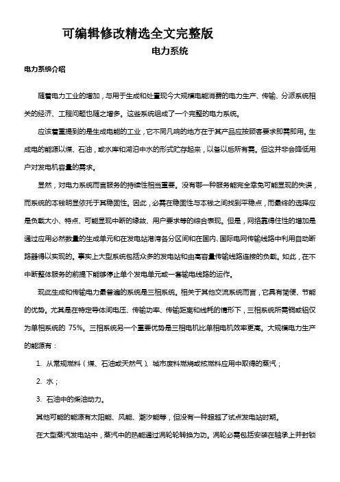
可编辑修改精选全文完整版电力系统电力系统介绍随着电力工业的增加,与用于生成和处置现今大规模电能消费的电力生产、传输、分派系统相关的经济、工程问题也随之增多。
这些系统组成了一个完整的电力系统。
应该着重提到的是生成电能的工业,它不同凡响的地方在于其产品应按顾客要求即需即用。
生成电的能源以煤、石油,或水库和湖泊中水的形式贮存起来,以备以后所有需。
但这并非会降低用户对发电机容量的需求。
显然,对电力系统而言服务的持续性相当重要。
没有哪一种服务能完全幸免可能显现的失误,而系统的本钱明显依托于其稳固性。
因此,必需在稳固性与本钱之间找到平稳点,而最终的选择应是负载大小、特点、可能显现中断的缘故、用户要求等的综合表现。
但是,网络靠得住性的增加是通过应用必然数量的生成单元和在发电站港湾各分区间和在国内、国际电网传输线路中利用自动断路器得以实现的。
事实上大型系统包括众多的发电站和由高容量传输线路连接的负载。
如此,在不中断整体服务的前提下能够停止单个发电单元或一套输电线路的运作。
现此生成和传输电力最普遍的系统是三相系统。
相关于其他交流系统而言,它具有简便、节能的优势。
尤其是在特定导体间电压、传输功率、传输距离和线耗的情形下,三相系统所需铜或铝仅为单相系统的75%。
三相系统另一个重要优势是三相电机比单相电机效率更高。
大规模电力生产的能源有:1.从常规燃料(煤、石油或天然气)、城市废料燃烧或核燃料应用中取得的蒸汽;2.水;3.石油中的柴油动力。
其他可能的能源有太阳能、风能、潮汐能等,但没有一种超越了试点发电站时期。
在大型蒸汽发电站中,蒸汽中的热能通过涡轮轮转换为功。
涡轮必需包括安装在轴承上并封锁于汽缸中的轴或转子。
转子由汽缸周围喷嘴喷射出的蒸汽流带动而平稳地转动。
蒸汽流撞击轴上的叶片。
中央电站采纳冷凝涡轮,即蒸汽在离开涡轮后会通过一冷凝器。
冷凝器通过其导管中大量冷水的循环来达到冷凝的成效,从而提高蒸汽的膨胀率、后继效率及涡轮的输出功率。
电力系统继电保护论文中英文资料Relay protection development present situation[Abstract ]reviewed our country electrical power system relay protection technological devil orpiment process,has outlined the microcomputer relay protection technology achievement, pro posed the future relay protection technological development tendency will be: Computerizes, n networked,protects, the control,the survey,the data communication integration and the artificial I intellectualization.[Key word ]relay protection present situation development,relay protections future development1 relay protection development present situationThe electrical power system rapid development to the relay protection proposed unceasingly t he new request,the electronic technology,computer technology and the communication rapid development unceasingly has poured into the new vigor for the relay protection technology de velopment,therefore,the relay protection technology is advantageous, has completed the deve lopment 4 historical stage in more than 40 years time。
The Transformer on load ﹠Introduction to DC Machine sThe Transformer on loadIt has been shown that a primary input voltage 1V can be transformed to any desired open-circuit secondary voltage 2E by a suitable choice of turns ratio. 2E is available for circulating a load current impedance. For the moment, a lagging power factor will be considered. The secondary current and the resulting ampere-turns 22N I will change the flux, tending to demagnetize the core, reduce m Φ and with it 1E . Because the primary leakage impedance drop is so low, a small alteration to 1E will cause an appreciable increase of primary current from 0I to a new value of 1I equal to ()()i jX R E V ++111/. The extra primary current and ampere-turns nearly cancel the whole of the secondary ampere-turns. This being so , the mutual flux suffers only a slight modification and requires practically the same net ampere-turns 10N I as on no load. The total primary ampere-turns are increased by an amount 22N I necessary to neutralize the same amount of secondary ampere-turns. In the vector equation , 102211N I N I N I =+; alternatively, 221011N I N I N I -=. At full load, the current 0I is only about 5% of the full-load current and so 1I is nearly equal to 122/N N I . Because in mind that 2121/N N E E =, the input kV A which is approximately 11I E is also approximately equal to the output kV A, 22I E .The physical current has increased, and with in the primary leakage flux to which it is proportional. The total flux linking the primary ,111Φ=Φ+Φ=Φm p , is shown unchanged because the total back e.m.f.,(dt d N E /111Φ-)is still equal and opposite to 1V . However, there has been a redistribution of flux and the mutual component has fallen due to the increase of 1Φ with 1I . Although the change is small, the secondary demand could not be met without a mutual flux and e.m.f. alteration to permit primary current to change. The net flux s Φlinking the secondary winding has been further reduced by the establishment of secondary leakage flux due to 2I , and this opposes m Φ. Although m Φ and2Φ are indicated separately , they combine to one resultant in the core which will be downwards at the instant shown. Thus the secondary terminal voltage is reduced to dt d N V S /22Φ-= which can be considered in two components, i.e. dt d N dt d N V m //2222Φ-Φ-=or vectorially 2222I jX E V -=. As for the primary, 2Φ is responsible for a substantially constant secondaryleakage inductance 222222/Λ=ΦN i N . It will be noticed that the primary leakage flux is responsiblefor part of the change in the secondary terminal voltage due to its effects on the mutual flux. The two leakage fluxes are closely related; 2Φ, for example, by its demagnetizing action on m Φ has caused the changes on the primary side which led to the establishment of primary leakage flux.If a low enough leading power factor is considered, the total secondary flux and the mutual flux are increased causing the secondary terminal voltage to rise with load. p Φ is unchanged in magnitude from the no load condition since, neglecting resistance, it still has to provide a total back e.m.f. equal to 1V . It is virtually the same as 11Φ, though now produced by the combined effect of primary and secondary ampere-turns. The mutual flux must still change with load to give a change of 1E and permit more primary current to flow. 1E has increased this time but due to the vector combination with 1V there is still an increase of primary current.Two more points should be made about the figures. Firstly, a unity turns ratio has been assumed for convenience so that '21E E =. Secondly, the physical picture is drawn for a different instant of time from the vector diagrams which show 0=Φm , if the horizontal axis is taken as usual, to be the zero time reference. There are instants in the cycle when primary leakage flux is zero, when the secondary leakage flux is zero, and when primary and secondary leakage flux is zero, and when primary and secondary leakage fluxes are in the same sense.The equivalent circuit already derived for the transformer with the secondary terminals open, can easily be extended to cover the loaded secondary by the addition of the secondary resistance and leakage reactance.Practically all transformers have a turns ratio different from unity although such an arrangement issometimes employed for the purposes of electrically isolating one circuit from another operating at the same voltage. To explain the case where 21N N ≠ the reaction of the secondary will be viewed from the primary winding. The reaction is experienced only in terms of the magnetizing force due to the secondary ampere-turns. There is no way of detecting from the primary side whether 2I is large and 2N small or vice versa, it is the product of current and turns which causes the reaction. Consequently, a secondary winding can be replaced by any number of different equivalent windings and load circuits which will give rise to an identical reaction on the primary .It is clearly convenient to change the secondary winding to an equivalent winding having the same number of turns 1N as the primary.With 2N changes to 1N , since the e.m.f.s are proportional to turns, 2212)/('E N N E = which is the same as 1E .For current, since the reaction ampere turns must be unchanged 1222'''N I N I = must be equal to 22N I .i.e. 2122)/(I N N I =.For impedance , since any secondary voltage V becomes V N N )/(21, and secondary current I becomes I N N )/(12, then any secondary impedance, including load impedance, must become I V N N I V /)/('/'221=. Consequently, 22212)/('R N N R = and 22212)/('X N N X = .If the primary turns are taken as reference turns, the process is called referring to the primary side. There are a few checks which can be made to see if the procedure outlined is valid.For example, the copper loss in the referred secondary winding must be the same as in the original secondary otherwise the primary would have to supply a different loss power. ''222R I must be equal to 222R I . )222122122/()/(N N R N N I ∙∙ does in fact reduce to 222R I .Similarly the stored magnetic energy in the leakage field )2/1(2LI which is proportional to 22'X I will be found to check as ''22X I . The referred secondary 2212221222)/()/(''I E N N I N N E I E kVA =∙==.The argument is sound, though at first it may have seemed suspect. In fact, if the actual secondarywinding was removed physically from the core and replaced by the equivalent winding and load circuit designed to give the parameters 1N ,'2R ,'2X and '2I , measurements from the primary terminals would be unable to detect any difference in secondary ampere-turns, kVA demand or copper loss, under normal power frequency operation.There is no point in choosing any basis other than equal turns on primary and referred secondary, but it is sometimes convenient to refer the primary to the secondary winding. In this case, if all the subscript 1’s are interchanged for the subscript 2’s, the necessary referring constants are easily found; e.g. 2'1R R ≈,21'X X ≈; similarly 1'2R R ≈ and 12'X X ≈.The equivalent circuit for the general case where 21N N ≠ except that m r has been added to allow for iron loss and an ideal lossless transformation has been included before the secondary terminals to return '2V to 2V .All calculations of internal voltage and power losses are made before this ideal transformation is applied. The behaviour of a transformer as detected at both sets of terminals is the same as the behaviour detected at the corresponding terminals of this circuit when the appropriate parameters are inserted. The slightly different representation showing the coils 1N and 2N side by side with a core in between is only used for convenience. On the transformer itself, the coils are , of course , wound round the same core.Very little error is introduced if the magnetising branch is transferred to the primary terminals, but a few anomalies will arise. For example ,the current shown flowing through the primary impedance is no longer the whole of the primary current. The error is quite small since 0I is usually such a small fraction of 1I . Slightly different answers may be obtained to a particular problem depending on whether or not allowance is made for this error. With this simplified circuit, the primary and referred secondary impedances can be added to give: 221211)/(Re N N R R += and 221211)/(N N X X Xe +=It should be pointed out that the equivalent circuit as derived here is only valid for normal operation at power frequencies; capacitance effects must be taken into account whenever the rate of change of voltage would give rise to appreciable capacitance currents, dt CdV I c /=. They are important at high voltages and at frequencies much beyond 100 cycles/sec. A further point is not theonly possible equivalent circuit even for power frequencies .An alternative , treating the transformer as a three-or four-terminal network, gives rise to a representation which is just as accurate and has some advantages for the circuit engineer who treats all devices as circuit elements with certain transfer properties. The circuit on this basis would have a turns ratio having a phase shift as well as a magnitude change, and the impedances would not be the same as those of the windings. The circuit would not explain the phenomena within the device like the effects of saturation, so for an understanding of internal behaviour .There are two ways of looking at the equivalent circuit:(a) viewed from the primary as a sink but the referred load impedance connected across '2V ,or (b) viewed from the secondary as a source of constant voltage 1V with internal drops due to 1Re and 1Xe . The magnetizing branch is sometimes omitted in this representation and so the circuit reduces to a generator producing a constant voltage 1E (actually equal to 1V ) and having an internal impedance jX R + (actually equal to 11Re jXe +).In either case, the parameters could be referred to the secondary winding and this may save calculation time .The resistances and reactances can be obtained from two simple light load tests.Introduction to DC MachinesDC machines are characterized by their versatility. By means of various combination of shunt, series, and separately excited field windings they can be designed to display a wide variety of volt-ampere or speed-torque characteristics for both dynamic and steadystate operation. Because of the ease with which they can be controlled , systems of DC machines are often used in applications requiring a wide range of motor speeds or precise control of motor output.The essential features of a DC machine are shown schematically. The stator has salient poles and is excited by one or more field coils. The air-gap flux distribution created by the field winding is symmetrical about the centerline of the field poles. This axis is called the field axis or direct axis.As we know , the AC voltage generated in each rotating armature coil is converted to DC in the external armature terminals by means of a rotating commutator and stationary brushes to which the armature leads are connected. The commutator-brush combination forms a mechanical rectifier,resulting in a DC armature voltage as well as an armature m.m.f. wave which is fixed in space. The brushes are located so that commutation occurs when the coil sides are in the neutral zone , midway between the field poles. The axis of the armature m.m.f. wave then in 90 electrical degrees from the axis of the field poles, i.e., in the quadrature axis. In the schematic representation the brushes are shown in quarature axis because this is the position of the coils to which they are connected. The armature m.m.f. wave then is along the brush axis as shown.. (The geometrical position of the brushes in an actual machine is approximately 90 electrical degrees from their position in the schematic diagram because of the shape of the end connections to the commutator.)The magnetic torque and the speed voltage appearing at the brushes are independent of the spatial waveform of the flux distribution; for convenience we shall continue to assume a sinusoidal flux-density wave in the air gap. The torque can then be found from the magnetic field viewpoint.The torque can be expressed in terms of the interaction of the direct-axis air-gap flux per pole d Φ and the space-fundamental component 1a F of the armature m.m.f. wave . With the brushes in the quadrature axis, the angle between these fields is 90 electrical degrees, and its sine equals unity. For a P pole machine 12)2(2a d F P T ϕπ= In which the minus sign has been dropped because the positive direction of the torque can be determined from physical reasoning. The space fundamental 1a F of the sawtooth armature m.m.f. wave is 8/2π times its peak. Substitution in above equation then gives a d a a d a i K i mPC T ϕϕπ==2 Where a i =current in external armature circuit;a C =total number of conductors in armature winding;m =number of parallel paths through winding;And mPC K a a π2=Is a constant fixed by the design of the winding.The rectified voltage generated in the armature has already been discussed before for an elementary single-coil armature. The effect of distributing the winding in several slots is shown in figure ,in which each of the rectified sine waves is the voltage generated in one of the coils, commutation taking place at the moment when the coil sides are in the neutral zone. The generated voltage as observed from the brushes is the sum of the rectified voltages of all the coils in series between brushes and is shown by the rippling line labeled a e in figure. With a dozen or so commutator segments per pole, the ripple becomes very small and the average generated voltage observed from the brushes equals the sum of the average values of the rectified coil voltages. The rectified voltage a e between brushes, known also as the speed voltage, is m d a m d a a W K W mPC e ϕϕπ==2 Where a K is the design constant. The rectified voltage of a distributed winding has the same average value as that of a concentrated coil. The difference is that the ripple is greatly reduced.From the above equations, with all variable expressed in SI units:m a a Tw i e =This equation simply says that the instantaneous electric power associated with the speed voltage equals the instantaneous mechanical power associated with the magnetic torque , the direction of power flow being determined by whether the machine is acting as a motor or generator.The direct-axis air-gap flux is produced by the combined m.m.f. f f i N ∑ of the field windings, the flux-m.m.f. characteristic being the magnetization curve for the particular iron geometry of the machine. In the magnetization curve, it is assumed that the armature m.m.f. wave is perpendicular to the field axis. It will be necessary to reexamine this assumption later in this chapter, where the effects of saturation are investigated more thoroughly. Because the armature e.m.f. is proportional to flux timesspeed, it is usually more convenient to express the magnetization curve in terms of the armature e.m.f. 0a e at a constant speed 0m w . The voltage a e for a given flux at any other speed m w is proportional to the speed,i.e. 00a m m a e w w e Figure shows the magnetization curve with only one field winding excited. This curve can easily be obtained by test methods, no knowledge of any design details being required.Over a fairly wide range of excitation the reluctance of the iron is negligible compared with that of the air gap. In this region the flux is linearly proportional to the total m.m.f. of the field windings, the constant of proportionality being the direct-axis air-gap permeance.The outstanding advantages of DC machines arise from the wide variety of operating characteristics which can be obtained by selection of the method of excitation of the field windings. The field windings may be separately excited from an external DC source, or they may be self-excited; i.e., the machine may supply its own excitation. The method of excitation profoundly influences not only the steady-state characteristics, but also the dynamic behavior of the machine in control systems.The connection diagram of a separately excited generator is given. The required field current is a very small fraction of the rated armature current. A small amount of power in the field circuit may control a relatively large amount of power in the armature circuit; i.e., the generator is a power amplifier. Separately excited generators are often used in feedback control systems when control of the armature voltage over a wide range is required. The field windings of self-excited generators may be supplied in three different ways. The field may be connected in series with the armature, resulting in a shunt generator, or the field may be in two sections, one of which is connected in series and the other in shunt with the armature, resulting in a compound generator. With self-excited generators residual magnetism must be present in the machine iron to get the self-excitation process started.In the typical steady-state volt-ampere characteristics, constant-speed primemovers being assumed. The relation between the steady-state generated e.m.f. a E and the terminal voltage t V isa a a t R I E V -=Where a I is the armature current output and a R is the armature circuit resistance. In a generator, a E is large than t V ; and the electromagnetic torque T is a countertorque opposing rotation.The terminal voltage of a separately excited generator decreases slightly with increase in the load current, principally because of the voltage drop in the armature resistance. The field current of a series generator is the same as the load current, so that the air-gap flux and hence the voltage vary widely with load. As a consequence, series generators are not often used. The voltage of shunt generators drops off somewhat with load. Compound generators are normally connected so that the m.m.f. of the series winding aids that of the shunt winding. The advantage is that through the action of the series winding the flux per pole can increase with load, resulting in a voltage output which is nearly constant. Usually, shunt winding contains many turns of comparatively heavy conductor because it must carry the full armature current of the machine. The voltage of both shunt and compound generators can be controlled over reasonable limits by means of rheostats in the shunt field. Any of the methods of excitation used for generators can also be used for motors. In the typical steady-state speed-torque characteristics, it is assumed that the motor terminals are supplied from a constant-voltage source. In a motor the relation between the e.m.f. a E generated in the armature and the terminal voltage t V isa a a t R I E V +=Where a I is now the armature current input. The generated e.m.f. a E is now smaller than the terminal voltage t V , the armature current is in the opposite direction to that in a motor, and the electromagnetic torque is in the direction to sustain rotation ofthe armature.In shunt and separately excited motors the field flux is nearly constant. Consequently, increased torque must be accompanied by a very nearly proportional increase in armature current and hence by a small decrease in counter e.m.f. to allow this increased current through the small armature resistance. Since counter e.m.f. is determined by flux and speed, the speed must drop slightly. Like the squirrel-cage induction motor ,the shunt motor is substantially a constant-speed motor having about 5 percent drop in speed from no load to full load. Starting torque and maximum torque are limited by the armature current that can be commutated successfully.An outstanding advantage of the shunt motor is ease of speed control. With a rheostat in the shunt-field circuit, the field current and flux per pole can be varied at will, and variation of flux causes the inverse variation of speed to maintain counter e.m.f. approximately equal to the impressed terminal voltage. A maximum speed range of about 4 or 5 to 1 can be obtained by this method, the limitation again being commutating conditions. By variation of the impressed armature voltage, very wide speed ranges can be obtained.In the series motor, increase in load is accompanied by increase in the armature current and m.m.f. and the stator field flux (provided the iron is not completely saturated). Because flux increases with load, speed must drop in order to maintain the balance between impressed voltage and counter e.m.f.; moreover, the increase in armature current caused by increased torque is smaller than in the shunt motor because of the increased flux. The series motor is therefore a varying-speed motor with a markedly drooping speed-load characteristic. For applications requiring heavy torque overloads, this characteristic is particularly advantageous because the corresponding power overloads are held to more reasonable values by the associated speed drops. Very favorable starting characteristics also result from the increase in flux with increased armature current.In the compound motor the series field may be connected either cumulatively, so that its.m.m.f.adds to that of the shunt field, or differentially, so that it opposes. The differential connection is very rarely used. A cumulatively compounded motor hasspeed-load characteristic intermediate between those of a shunt and a series motor, the drop of speed with load depending on the relative number of ampere-turns in the shunt and series fields. It does not have the disadvantage of very high light-load speed associated with a series motor, but it retains to a considerable degree the advantages of series excitation.The application advantages of DC machines lie in the variety of performance characteristics offered by the possibilities of shunt, series, and compound excitation. Some of these characteristics have been touched upon briefly in this article. Still greater possibilities exist if additional sets of brushes are added so that other voltages can be obtained from the commutator. Thus the versatility of DC machine systems and their adaptability to control, both manual and automatic, are their outstanding features.负载运行的变压器及直流电机导论负载运行的变压器通过选择合适的匝数比,一次侧输入电压1V 可任意转换成所希望的二次侧开路电压2E 。
外文资料翻译Power System AutomationPower system integration is the act of communication data to, or among IED s in the I&C system and remote users. Substation integration refers to combining data from the IED′s local to a substation so that there is a single point of contact in the substation for all of the I&C data. Poletop devices often communicate to the substation via wireless or fiber connections. Remote and local substation and feeder control is passed through the substation controller acting as a single point of contact. Some systems bypass the substation controller by using direct connections to the poletop devices, such as RTU s, protective relays, and controllers.Power system automation is the act of automatically controlling the power system via I&C devices. Substation automation refers to using IED data, control and automation capabilities within the substation, and control commands from remote users to control power system devices. Since true substation automation relies on substation integration, the terms are often used interchangeably.Power system automation includes processes associated with generation and delivery of power. A subset of the process deal with delivery of power at transmission and distribution levels, which is power delivery automation. Together, monitoring and control of power delivery system in the substation and on the poletop reduce the occurrence of outages and shorten the duration of outages that do occur. The IED′s, communications protocols, and communications methods described in previous sections, work together as a system to perform power system automation.Though each utility is unique, most consider power delivery automation of transmission and distribution substation and feeders to include : Supervisory Control and Data Acquisition(SCADA)-operatorsupervision and control;Distribution Automation-fault location, auto-isolation, auto-sectionalizing, and auto-restoration;Substation Automation-breaker failure, reclosing, battery monitoring, dead substation transfer, and substation load transfer;Energy Management System (EMS)-load flow, VAR and voltage monitoring and control, generation control, transformer and feeder load balancing;Fault analysis and device maintenance.System without automated control still have the advantages of remote monitoring and operator control of power system devices, which includes: Remote monitoring and control of circuit breakers and automated switches;Remote monitoring of non-automated switches and fuses;Remote monitoring and control of capacitor banks;Remote monitoring and voltage control;Remote power quality monitoring and control.IED s described in the overview are used to perform power system integration and automation. Most designs require that the one IED act as the substation controller and perform data acquisition and control of the other IED s. The substation controllers is often called upon to support system automation tasks as well. The communications industry uses the term client/server for a device that acts as a master, or client, retrieving data from some devices and then acts as a slaver, a server, sending this data to other devices. The client/server collecting and concentrating dynamically. A data concentrator creates a substation databases by collecting and concentrating dynamic data from several devices. In this fashion, essential subsets of data from each IED are forwarded to a master through one data transfer. The concentrator databases is used to pass data between IED s that are not directly connected.A substation archive client/server collects and archives data from several devices. The archive data is retrieved when it is convenient for the userto do so.The age of the IED s now in substations varies widely. Many of these IED s are still useful but lack the most recent protocols. A communications processor that can communicate with each IED via a unique baud rate and protocol extends the time that each IED is useful. Using a communications processor for substation integration also easily accommodates future IED s. It is rare for all existing IED s to be discarded during a substation integration upgrade project.The benefits of monitoring, remote control, and automation of power delivery include improved employee and public safety, and deferment of the cost of purchasing new equipment. Also, reduced operation and maintenance costs are realized through improved use of existing facilities and optimized performance of the power system through reduced losses associated with outages and improved voltage profile. Collection of information can result in better planning and system design, and increased customer satisfaction will result from improved responsiveness, service reliability, and power quality.Power system automation includes a variety of equipment. The principal items are listed and briefly described below.Instrument transformers are used to sense power system current and voltage. They are physically connected to power system apparatus and convert the actual power system signals, which includes high voltage and current magnitudes, down to lower signal levels.Transducers convert the analog output of an instrument transformer from one magnitude to another or from one value type to another, such as from an ac current to dc voltage.As the name implies, a remote terminal device, RTU, is an IED that can be installed in a remote location, and acts as a termination point for filed contacts. A dedicated pair of copper conductors are used to sense every contract and transducer value. These conductors originated at the power system device, are installed in trenches or overhead cable trays, and are thenterminated on panels within the RTU. The RTU can transfer collected data to other devices and receive data and control commands from other device through a serial port. User programmable RTUs are referred to as “smart RTUs.”A communication switch is a device that switches between several serial ports when it is told to do so. The remote user initiates communications with the port switch via a connection to the substation , typically a leased line or dial-up telephone connection. Once connected, the user can route their communication through the port switch to one of the connected substation IEDs. The port switch merely “passes through” the IED communication.A meter is an IED that is used to create accurate measurement of power system current, voltage, and power values. Metering values such as demand and peak are saved within the meter to create historical information about the activity of the power system.A digital fault recorder ,is an IED that records information about power system disturbances. It is capable of storing data in digital format when triggered by conditions detected on the power system. Harmonics, frequency, and voltage are examples of data captured by DFRs.Load tap changer are devices used to change the tap position on transformers. These devices work automatically or can be controlled via another local IED or form a remote operator or process.Recloser controllers remotely control the operation of automated reclosers and switches. These devices monitor and store power system conditions and determine when to perform control actions. They also accept commands form a remote operator or process.电力系统自动化电力系统集成是在I&C系统中的IED和远程用户之间进行数据通信的操作。
Ⅰ.system analysis and synthesis1.Analysis(1)In the speed and current dual closed-loop speed control system, in order to change the motor speed, what parameters should be regulating? Change speed regulator Kn magnification work? Power electronic converter to change the magnification factor Ks work? Change the speed of the feedback coefficient of work? To change the motor's stall current system should adjust the parameters of what?A: To change the motor speed, change speed regulator Kn magnification and power electronic converters will not work magnification factor Ks, stable when n = Un = Un *, so the only change in the value of a given coefficient of Un * and feedback before. To change the motor's stall current, only need to change the same value given Uim * and feedback coefficient, because the stability, Uim * = Idm, can be drawn from the type(2) Speed, the current double closed-loop speed control system when the steady-state operation, the two regulator input voltage and output voltage deviation is the number?A: The speed and current dual closed-loop speed control system when the steady-state operation, the two regulators are the input bias voltage is zero, by the formula n = Un = Un *, n = n; Uim * = Idm, Idm = Idl.(3) In the speed and current dual closed-loop speed control system, the two regulators are PI regulator. When the system is running with rated load, the speed feedback line suddenly disconnected, the system re-enter the steady-state, the current regulator is the input bias voltage to zero? Why?A: When the system is running with rated load, the speed feedback line suddenly disconnected, then Un = 0, = Un *- Un = Un *, so that Ui to reach Uim, 0, rate of increase in n, when the system after re-entering the steady-state , that is, Id = Idl, then, = Uim *- Idl 0, are no longer changes, changes in rotational speed n is no longer, but at this time than the rotational speed n at the time of the feedback line speed to break big.(4) Why is the speed with integral control system is not static poor?A: Speed regulator integral system, to achieve non-static error is due to the characteristics of integral control regulator, that is, the accumulation of points and the role of memory.(5) Double-loop speed control system (PI), load changes, Idl> Idm, asked bicyclol speed control system ASR and ACR how-conditioning, the result?A: When the load changes, Idl> Idm, speed decreased rapidly, the current Id soon to Idm, and of limited amplitude, rapid rate of ASR saturation, ACR has been limiting conditions, to form a blocking phenomenon, long-running will damage the system.2. SystemSpeed regulator and current regulator in the Double Loop DC Motor Control System can be summarized as follows:(1). The role of speed regulatorSpeed regulator is a speed control system of the dominant regulator, which allows speed n will soon change with a given voltage Un * changes in steady-state speed error can be reduced, if the PI regulator can achieve the non-static error.1) The effect of load changes in the role of anti-disturbance.2) The output amplitude of the decision limit the maximum allowable motor current.(2) The role of current regulator1) As a regulator of the inner ring, outer ring at the speed of the adjustment process, it makes the current closely followed the given voltage Ui * (that is, the outer ring modulator output) changes.2) Fluctuations in voltage from the role of disturbance rejection in time.3) The speed of the dynamic process of ensuring that the maximum allowable motor current, thereby speeding up the dynamic process.4) When the motor overload or stall when the armature current limit of the maximum, automatic protection from the role of acceleration. Once the faultdisappears, the system automatically return to normal. Yesterday, the role of the reliable operation is very important.Ⅱdouble-loop speed control system common faults analysis1.Introduction of a system(1). Double-loop speed control system components in Figure 1. Current loop: from the current regulator LT, trigger CF (input transformation for the CSR), silicon-controlled rectifier bridge, motor armature and current loop transform LB component. the speed of outer ring: the speed regulator from ST, current loop, such as link inertia, motor and load moment of inertia and the speed of transformation components SB. in the double-loop speed control system, the speed of the decision loop of the running characteristics of the whole system and stability, and play a leading role, and to change the current ring plays the role of the internal structure of the system is dependent, but since it is as a whole to participate in the closed-loop speed to the speed of a direct impact on the work of the closed-loop, it must first good debugging current loop, and then testing the speed of outer ring, so that the whole system has good dynamic performance.(2). Double-loop speed control system of the typical working condition1) Start (or the speed):ST in the start-up process has been saturated, so that the speed of this loop in the equivalent open-loop state. System only in the constant current loop under the regulation to ensure the motor at a constant current of the maximum allowable under the start-up.Figure 1 double-loop speed control system structure2) slow down (or stop):ST at this time to reach the output amplitude of the reverse limit. Main circuit current by the bridge is reduced to zero after the inverter. LT and CSR output will soon reach the maximum reverse. CF pulse output to reach βmin, current loop for open-loop. motor torque under deceleration until the motor speed close to the given new value, current loop and speed loop one after another into the closed-loop work, motor in the new value of a given run .3) Grid voltage fluctuation: This motor because of the larger moment of inertia, which caused the first change in armature current, ST output also did not change the effect of current loop, LT rapidly changing the output so that angle α be adjusted quickly, so the impact on the speed .4)Small changes in load: in the operation, load changes, will cause the motor speed deviation from the given value. speed up the recovery process and the aforementioned speed (or deceleration) is similar to the process.2. Common Fault Analysis and Processing(1) The normal supply voltage, thyristor rectifier output waveform arrhythmia caused by this phenomenon is due to trigger sawtooth slope caused inconsistency. Sawtooth slope adjust potentiometer, the output waveform uniformity could be achieved. in the adjustment process to strike a balance between Qi, this point should be paid attention to the actual debugging.(2) DC Motor Analysis of mechanical properties of soft thyristor DC motor system, when the current intermittent mechanical properties when the first no-load speed is characterized by high ideals, and the second is characterized by mechanical properties of soft . The so-called mechanical features soft, that is, small changes in load will cause great changes in speed. oscilloscope to observe when using the bridge rectifier output waveform, one may find that missing relative. at this time need to check whether the trigger has pulse output, fast whether the fuse melting, whether the breakdown or thyristor circuit,synchronous transformer is damaged, whether the lack of power. to identify the problems, can be resolved.(3) The speed of the speed of instability caused by many factors of instability:1) Electric guns are not firmly fixed or with the host of different axis .2) The parameters of the speed regulator inappropriate. Respond to the dynamic parameters to adjust (change the ratio of integral parameters ) .3) Of a speed control system there are(or bad)4) May be caused as a result of interference. should be found to interfere with the reasons for taking anti-jamming measures.(4) A little to the set rated motor speed is higher than that should first check whether it is normal for the external control system, such as outside the normal control system, it may be given points, speed regulator, current regulator, such as caused by link failure. Should be cut off the main circuit power supply, only the control system to the electricity, not a given in the case, testing each of the key points (such as the current regulator, voltage regulator, etc. of the potential. and then given together with the former to one by one after each of the key points to check the potential changes, you can find out the fault lies.(5) Bridge rectifier output voltage is not high stressed 1) the speed regulator and current regulator limiter too small, should be liberalized in accordance with appropriate amplitude threshold .2) than the speed feedback signal, in that they can reduce the rate of appropriate feedback signals.(6) To the timing system still in the absence of low-speed operation (that is, the phenomenon of emergence of reptiles) This is because the system of "zero drift" caused by. When the input signal is zero, the output voltage by the input amplification stage of the offset potentiometer decisions can be offset by adjusting the potential allows α = 90 °, at this time to zero output voltage rectification system, the electrical will not crawl.(7) With a given system can not runShould first check whether it is normal for the external control system, such as outside the normal control system, it may be given points, speed regulator, currentregulator, such as caused by link failure. Shall be cut off main circuit power supply, only the control system to the electricity, not Add the given circumstances, the key points of each test (such as the current regulator, voltage regulator, etc.) of the potential. and then combined with a given, after the previous one by one to each of the key points to check the potential changes, that is, where to find fault. (8) Lack of control accuracy in the distributor for a given run-time external control often requires precision sufficient parking in order to work properly. If poor precision parking, you can adjust the speed of the appropriate regulator of the PI link, generally by reducing the the ratio of the integral part of efforts to get satisfactory results.(9) Reversible system oscillation 1) open-loop system in the state (the main circuit disconnect) the oscillation can be changed at this time given the previous inspection to the key points of the potential changes. If a given unchanged, but the potential is still a point of change, here is the crux of .2) system in the state when the closed-loop oscillation, in which case in order to ensure the safety of the electrical load should be replaced by the general resistance of the load, if there is no suitable resistance box which can be used in place of the two electric sub-series. inspection methods and similar open-loop, focusing on the link to check is: given points, level detection, operation control, such as the speed regulator. oscillations are often caused as a result of operational amplifiers, such as damage to electronic components , system parameters caused by improper, according to the specific circumstances, properly addressed.一、系统分析与综合1.系统分析(1)在转速、电流双闭环调速系统中,若要改变电动机的转速,应调节什么参数?改变转速调节器的放大倍数Kn行不行?改变电力电子变换器的放大系数Ks行不行?改变转速反馈系数∂行不行?若要改变电动机的堵转电流,应调节系统中的什么参数?答:若要改变电动机的转速,改变转速调节器的放大倍数Kn和电力电子变换器的放大系数Ks都不行,稳定时∂n=Un=Un*,所以只有改变给定值Un*和反馈系数∂才行。
附录一:外文原文Super capacitors - An OverviewKey words: Electrostatic capacitor; Electrolytic capacitor; Ceramic capacitor;Electrical double layer capacitor; Super Capacitor1.INTRODUCTIONThis paper offers a concise review on the renaissance of a conventional capacitor toelectrochemical double layer capacitor or super capacitor. Capacitors are fundamental electrical circuitelements that store electrical energy in the order of microfarads and assist in filtering. Capacitors havetwo main applications; one of which is a function to charge or discharge electricity. This function isapplied to smoothing circuits of power supplies, backup circuits of microcomputers, and timer circuitsthat make use of the periods to charge or discharge electricity. The other is a function to block the flowof DC. This function is applied to filters that extract or eliminate particular frequencies. This isindispensable to circuits where excellent frequency characteristics are required. Electrolytic capacitorsare next generation capacitors which are commercialized in full scale. They are similar to batteries in cell construction but the anode and cathode materials remain the same. They are aluminum, tantalum and ceramic capacitors where they use solid/liquid electrolytes with a separator between two symmetrical electro des.An electrochemical capacitor (EC), often called a Super capacitor or Ultra capacitor, stores electrical charge in the electric double layer at a surface-electrolyte interface, primarily in high-surface-area carbon. Because of the high surface area and the thinness of the double layer, these devices can have very a high specific and volumetric capacitance. This enables them to combine a previously unattainable capacitance density with an essentially unlimited charge/discharge cycle life. The operational voltage per cell ,limited only by the breakdown potential of the electrolyte, is usually<1 or <3 volts per cell for aqueous or organic electrolytes respectively.The concept of storing electrical energy in the electric double layer that isformed at the interface between an electrolyte and a solid has been known since the late 1800s. The first electrical device using double-layer charge storage was reported in 1957 by H.I. Becker of General Electric (U.S. Patent 2,800,616).Unfortunately, Becker’s device was imp ractical in that, similarly to a flooded battery, both electrodes needed to be immersed in a container of electrolyte, and the device was never comercialised.Becker did, however, appreciate the large capacitance values subsequently achieved by Robert A. Rightmire, a chemist at the Standard Oil Company of Ohio (SOHIO), to whom can be attributed the invention of the device in the format now commonly used. His patent (U.S. 3,288,641), filed in 1962 and awarded in late November 1966, and a follow-on patent (U.S. Patent 3,536,963) by fellow SOHIO researcher Donald L. Boos in 1970, form the basis for the many hundreds of subsequent patents and journal articles covering all aspects of EC technology.This technology has grown into an industrywith sales worth severalhundred million dollars per year. It is an in dustry that is poised today for rapid growth in the near term with the expansion of power quality needs and emerging transportation applications.Following the commercial introduction of NEC’s Super Capacitor in 1978, under licence from SOHIO, EC have evolved through several generations of designs. Initially they were used as back-up power devices for v is for cells ranging in size from small millifarad size devices with exceptional pulse power performance up to devices rated at hundreds of thousands of farads, with systems in some applications operating at up to 1,500 volts. The technology is seeing increasingly broad use, replacing batteriesolatile clock chips and complementary metal-oxide-semiconductor (CMOS) computer memories. But many other applications have emerged over the past 30 years, including portable wireless communication, enhanced power quality for distributed power generation systems, industrial actuator power sources, and high-efficiency energy storage for electric vehicles(EVs) and hybrid electric vehicles (HEVs).Overall, the unique attributes of ECs often complement the weaknesses of other power sources like batteries and fuel cells.Early ECs were generally rated at a few volts and had capacitance values measured from fractions of farads up to several farads. The trend today in some cases and in others complementing their performance.The third generation evolution is the electric double layer capacitor, where the electrical charge stored at a metal/electrolyte interface is exploited to construct astorage device. The interface can store electrical charge in the order of 610Farad. The main component in the electrode construction is activated carbon. Though this concept was initialized and industrialized some 40 years ago, there was a stagnancy in research until recent times; the need for this revival of interest arises due to the increasing demands for electrical energy storage in certain current applications like digital electronic devices, implantable medical devices and stop/start operation in vehicle traction which need very short high power pulses that could be fulfilled by electric double layer capacitors. They are complementary to batteries as they deliver high power density and low energy density. They also have longer cycle life than batteries and possess higher energy density as compared to conventional capacitors. This has led to new concepts of the so-called hybrid charge storage devices in which electrochemical capacitor is interfaced with a fuel cell or a battery. These capacitors using carbon as the main electrode material for both anode and cathode with organic and aqueous electrolytes are commercialized and used in day to-day applications. Fig.1 presents the three types of capacitors depicting the basic differences in their design and construction.Figure 1.Schematic presentation of electrostatic capacitor, electrolytic capacitor and electrical double layer capacitor.EDLCs, however suffer from low energy density. To rectify these problems, recently researchers try to incorporate transition metal oxides along with carbon in the electrode materials. When the electrode materials consist of transition metal oxides, then the electrosorption or redox processes enhance the value of specific capacitance ca. 10 -100 times depending on the nature of oxides. In such a situation, the EDLC is called as super capacitor or pseudo capacitor . This is the fourth generation capacitor. Performance of a super capacitor combines simultaneously two kinds of energy storage, i.e. non-faradic charge as in EDLC capacitors and faradaic charge similar toprocesses proceeding in batteries. The market for EC devices used for memory protection in electronic circuitry is about $150-200 million annually. New potential applications for ECs include the portable electronic device market, the power quality market, due particularly to distributed generation and low-emission hybrid cars, buses and trucks. There are some published reviews on capacitors and super capacitors . In the present overview, the evolution of electrochemical double layer capacitors starting from simple electrostatic capacitors is summarized.2. EXPERIMENTAL PARTThe invention of Leiden jar in 1745 started the capacitor technology; since then, there has been tremendous progress in this field. In the beginning, capacitors are used primarily in electrical and electronic products, but today they are used in fields ranging from industrial application to automobiles, aircraft and space, medicine, computers, games and power supply circuits. Capacitors are made from two metallic electrodes (mainly Si) placed in mutual opposition with an insulating material (dielectric) between the electrodes for accumulating an electrical charge. The basic equation relating to the capacitors is:C = εS/d (1)where C(μF) is the electrostatic capacity, the dielectric constant of the dielectric, S (cm2) the surface area of the electrode and d (cm) the thickness of the dielectric. The charge accumulating principle can be described as follows: when a battery is connected to the capacitor, flow of current induces the flow of electrons so that electrons are attracted to the positive terminal of the battery and so they flow towards the power source. As a result, an electron deficiency develops at the positive side, which becomes positively charged and an electron surplus develops at the negative side, which becomes negatively charged. This electron flow continues until the potential difference between the two electrodes becomes equal to the battery voltage. Thus the capacitor gets charged. Once the battery is removed, the electrons flow from the negative side to the side with an electron deficiency; this process leads to discharging. The conventional capacitors yield capacitance in the range of 0.1 to 1 μF with a voltage range of 50 to 400 V. Various materials such as paper (ε, 1.2-2.6), paraffin (ε 1.9-2.4), polyethylene (2.2-2.4), polystyrene (ε, 2.5-2.7), ebonite (ε, 2-3.5), polyethylene tetraphtharate (ε,3.1-3.2), water (ε, 80) sulfur(ε, 2-4.2), steatite porcelain (ε, 6-7), Al porcelain (ε, 8-10), mica(ε, 5-7)and insulated mineral oil (ε, 2.2-2.4) are used as dielectrics in capacitors.The capacitance output of these silicon based capacitors is limited and has to cope with low surface-to volume ratios of these electrodes. To increase the capacitance, as per eq., one has to increase to ∂or S and decrease; however the ∂value is largely determined by the working voltage and cannot be tampered. When aiming at high capacitance densities, it is necessary to combine the mutual benefits achieved with a high permittivity insulator material and an increased effective surface area. With Si as the substrate material, electrochemical etching produces effective surface area. The surface area of this material gets enlarged by two orders of magnitude compared to unetched surface. Electrochemically formed macroporous Si has been used for the preparation of high aspect ratio capacitors with layered SiO2/Si3N4/SiO2 insulators. Research work on the modification of conventional capacitors to increase the specific capacitance is also in progress. Approximately 30 times higher capacitance densities are reported recently for Si/Al2O3/ZnO: Al capacitor where Si is electrochemically etched porous one. Another way identified to increase the surface area of the electrodes is to form anodically formed oxides (Al, Ta); however, ceramic capacitors are based on the high dielectric constant rather than the electrode area.3. ELECTROLYTIC CAPACITORSThe next generation capacitors are the electrolytic capacitors; they are of Ta, Al and ceramic electrolytic capacitors. Electrolytic capacitors use an electrolyte as conductor between the dielectrics and an electrode. A typical aluminum electrolytic capacitor includes an anode foil and a cathode foil processed by surface enlargement and or formation treatments. Usually, the dielectric film is fabricated by anodizing high purity Al foil for high voltage applications in boric acid solutions. The thickness of the dielectric film is related to the working voltage of the aluminum electrolytic capacitor. After cutting to a specific size according to the design specification, a laminate made up of an anode foil, a cathode foil which is opposed to the dielectric film of the anode foil and a separator interposed between the anode and cathode foils, is wound to provide an element. The wound element does not have any electricalcharacteristics of electrolytic capacitor yet until completely dipped in an electrolyte for driving and housed in a metallic sheathed package in cylindrical form with a closed-end equipping a releaser. Furthermore, a sealing material made of elastic rubber is inserted into an open-end section of the sheathed package and the open-end section of the sheathed package by drawing, whereby an aluminum electrolytic capacitor is constituted. Electrolytic aluminum capacitors are mainly used as power supplies for automobiles, aircraft, space vehicles, computers, monitors, motherboards of personal computers and other electronics.There are two types of tantalum capacitors commercially available in the market; wet electrolytic capacitors which use sulfuric acid as the electrolyte and solid electrolytic capacitors which use MnO2 as the solid electrolyte. Though the capacitances derived from both Ta and Al capacitors are the same, Ta capacitors are superior to Al capacitors in temperature and frequency characteristics. For analog signal systems, Al capacitors produce a current-spike noise which does not happen in Ta capacitors. In other words, Ta capacitors are preferred for circuits which need high stability characteristics. The total world wide production of Al electrolytic capacitors amounts to US$ 3.8 billion, 99% of which are of the wet type. Unlike Ta solid electrolytic capacitors, the solid electrolyte materials used are of organic origin; polypyrrole, a functional polymer and TCNQ (7,7, 8, 8- tetracyanoquniodimethane) an organic semiconductor. Next, MnO2 solid electrolyte material is formed on the surface of that dielectric layer and on top of that a layer of polypyrrole organic solid electrolyte material is formed by electrolytic synthesis. Following this, the positive and negative electrodes are mounted to complete the electronic component. However, the capacitances of these electrolytic capacitors are in the range 0.1 to 10F with a voltage profile of 25 to 50 V.The history of development of electrolytic capacitors which were mass produced in the past as well as today is presented by S. Niwa and Y. Taketani . Many researchers try to improve the performance of these electrolytic capacitors by modifying the electrode or electrolyte. Generally, the increases in effective surface area (S) are achieved by electrolytic etching of aluminum substrate before anodization, but now it faces with the limit. It is also very difficult to decrease d because the d value is largely decided when the working voltages are decided. Increase in may be a possible routine to form composite dielectric layers by incorporating relatively large value compounds. Replacement of MnO2 by polypyrrole solid electrolyte was reported to reduce electrostatic resistance due to its higher conductivity; aromaticsulfonate ions were used as charge compensating dopant ions .A tantalum capacitor with Ta metal as anode, polypyrrole as cathode and Ta2O5 dielectric layer was also reported. In the Al solid electrolytic capacitors, polyaniline doped with inorganic and organic acids was also studied as counter electrode. In yet another work, Al solid electrolytic capacitor with etched Al foil as anode, polyaniline / polypyrrrole as cathode and Al2O3 as dielectric was developed. Ethylene carbonate based organic electrolytes and -butyrolactone based electrolytes have been tried as operating electrolytes in Al electrolytic capacitors. Masuda et al. have obtained high capacitance by electrochemically anodizing rapidly quenching Al-Ti alloy foil. Many researchers have tried the other combination of alloys such as Al-Zr, Al-Si, Al-Ti, Al-Nb and Al-Ta composite oxide films. Composite oxide films of Al2O3-(Ba0.5Sr0.5TiO3) and Al2O3- Bi4Ti3O12 on low-voltage etched aluminum foil were also studied. Nb-Ta-Al for Ta electrolytic capacitors was also tried as anode material .A ceramic capacitor is a capacitor constructed of alternating layers of metal and ceramic, with the ceramic material acting as the dielectric. Multilayer ceramic capacitors (MLCs) typically consist of ~100 alternate layers of electrode and dielectric ceramics sandwiched between two ceramic cover layers. They are fabricated by screen-printing of electrode layers on dielectric layers and co-sintering of the laminate. Conventionally, Ag-Pd is used as the electrode material and BaTiO3 is used as the dielectric ceramic. From 2000 onwards, the MLCs market has been growing in pace with the exponential development of communications. They are produced in the capacitance range of 10 F (normally the range of Ta and Al electrolytic capacitors); they are highly useful in high frequency applications. Historically, a ceramic capacitor is a two-terminal non-polar device. The classical ceramic capacitor is the disc capacitor. This device predates the transistor and was used extensively in vacuum-tube equipment (e.g radio receivers) from c. a. 1930 through the 1950s and in discrete transistor equipment from the 1950s through the 1980s. As of 2007, ceramic disc capacitors are in widespread use in electronic equipment, providing high capacity and small size at low price compared to the other types.The other ceramic materials that have been identified and used are CaZrO3, MgTiO3, SrTiO3 etc. A typical 10 F MLC is a chip of size (3.2 x 1.6 x 1.5 mm). Mn, Ca, Pd , Ag etc are some of the other internal electrodes used. Linear dielectrics and antiferroelectrics based o strontium titante have been developed for high voltage disk capacitors. These are applicable for MLCs with thinner layers because of their high coercive fields. One of the most critical material processing parameters is the degreeof homogeneous mixing of additive in the slurry. The binder distribution in the green ceramic sheet, the degree of surface roughness, fine size nickel powder, formation of green sheet, electrode deposition ad sheet stacking etc play a crucial role in the process technology. Any one of these facts if mishandled would result in the failure of the device. For instance, providing a roughess of 5 m thick green sheet to 0.5 m is mandatory so that a smooth contact surface with the inner nickel electrode can be established. This is a very important factor in avoiding the concentration of electric filed at asperities, where the charge emission from the electrode is accelerated, resulting in short failure. Conventional sheet/printing method has a technical limit of producing a thickness around 1 m dielectric; in order to decrease the thickness further, thin film technologies like CVD, sputtering, plasma-spray etc has to be used.The other types of capacitors are film capacitors which use thin polyester film and polypropylene film as dielectrics and meta-glazed capacitors which incorporate electrode plates made of film vacuum evaporated with metal such as Al. Films can be of polyester, polypropylene or polycarbonate make. Also capacitors are specified depending on the dielectric used such as polyester film capacitor, polypropylene capacitor, mica capacitor, metallized polyester film capacitor etc.4. DOUBLE LAYER CAPACITORSElectric/electrochemical double layer capacitor (EDLC) is a unique electrical storage device, which can store much more energy than conventional capacitors and offer much higher power densitythan batteries. EDLCs fill up the gap between the batteries and the conventional capacitor, allowing applications for various power and energy requirements i.e., back up power sources for electronic devices, load-leveling, engine start or acceleration for hybrid vehicles and electricity storage generated from solar or wind energy. EDLC works on the principle of double-layer capacitance at the electrode/electrolyte interface where electric charges are accumulated on the electrode surfaces and ions of opposite charge are arranged on the electrolyte side.Figure 2.Charge storage mechanism of an EDLC cell under idle and charged conditions.Fig. 2 shows the mechanism of charge storage in an EDLC cell and Fig. 3 shows the configuration of an typical EDLC cell. There are two main types of double layer capacitors as classified by the charge storage mechanism: (i) electrical double-layer capacitor; (ii) electrochemical double layer capacitor or super/pseudocapacitor. An EDLC stores energy in the double-layer at the electrode/electrolyte interface, whereas the supercapacitor sustains a Faradic reaction between the electrode and the electrolyte in a suitable potential window. Thus the electrode material used for the construction of the cell for the former is mainly carbon material while for the latter, the electrode material consist of either transition metal oxides or mixtures of carbon and metal oxides/polymers. The electrolytes can be either aqueous or non-aqueous depending on the mode of construction of EDLC cell.Figure 3.Typical configuration of an EDLC cellThere are two general directions of interest. One is the long term goal of the development of electrical propulsion for vehicles, and the other is the rapid growth of portable electronic devices that require power sources with maximum energy content and the lowest possible size and weight.5. CONCLUSIONSAccording to a market survey by Montana, super capacitors are becoming a promising solution for brake energy storage in rail vehicles. The expected technological development outside railway sector is also shown to be highly dynamic: diesel electric vehicles, catenary free operation of city light rail, starting system for diesel engines, hybrid-electric cars, industrial applications, elevators, pallet trucks etc. The time horizon expected for development is next 5 to 10 years. The main development goals will be,· long life time· increase of the rated voltage· improvements of the range of operating temperature· increase of the energy and power densitiesVery recently, hybrid car is introduced in the market but it is turned to be very expensive and out of common man’s reach. Shortage and cost of fossil fuels already instigated alternate technologies viable for traction purposes. In such a situation,EDLCs are also useful to store energy generated from non-conventional energy sources. A future possibility of service centers set up for EDLC supply similar to petrol (as on date) is not far as the main setbacks in technology development may take a decade for fruitful results.附录二:外文译文超级电容器-概述关键词:静电电容,电解电容器,陶瓷电容器,双电层 ,电容器,超级电容器1.引言本文为电化学双层电容器或超级电容器提供在一台常规电容器,简明的介绍新生的电化学双电层电容器或超级电容器。
翻译原文 (4)Photovoltaic (PV) Electric Systems (4)The Advantages of Mitsubishi Solar Panels (5)1光伏电力系统光伏电力系统利用太阳能电池吸收太阳光线,并将这种能量转化成电能。
这个系统让广大家庭通过一种清洁,可靠,平静的方式来产生电能,这样就可以补偿将来的部分电能支出,也减少了对输电网的依赖。
太阳能电池一般是由经改进的硅,或者其他能够吸收阳光并将之转化成电能的半导体材料制成。
太阳能电池是相当耐用的(1954年在美国安装的第一个光伏电力系统至今仍在运营)。
绝大多数的生厂商都担保自己的产品的电源输出至少维持20年。
但大多数的有关太阳能研究的专家认为一个光伏电力系统至少能维持25到30年。
1.1 太阳能电池的类型目前有单晶硅,多晶硅和薄膜三种基本形式的光伏组件。
这些类型的电池工作效率都很好但单晶硅电池效率最好。
薄膜技术的电池以成本低为特色,而且伴随着太阳能电池板的发展它的效率也在不断地提高。
越来越多的生厂商以及各种各样的电池型号在当今市场上出现。
一个太阳能技术的支持者可以帮你分析各个系统的利弊,如此你就可以得到为你所用数十年的最佳的系统设计方案。
1.2光伏电力系统如何运作光电板通常安装在建筑物顶部,通过逆变器来引到建筑物中。
逆变器将通过太阳能板产生的直流电转化成交流电,而在当今美国交流电是向建筑提供电动力的主要形式。
朝南方向的太阳能板能使能量的收集效果最大化,大部分都是与建筑物顶部成60度的位置安放太阳能电池。
有关太阳能电池发电的更多的信息,可以查询Cooler Planet’s的《太阳能电池如何工作》。
朝南方向的太阳能板能使能量的收集效果最大化,大部分都是与建筑物顶部成60度的位置安放太阳能电池。
1.3 太阳能电池板与光伏建筑一体化太阳能电池板是用于捕获太阳光的平面板,他们以阵列的形式安装在建筑物顶部或者柱子上。
他们是传统的用于获得太阳能的阵列形式。
附录Ⅰ:专业相关文献翻译Faults on power systemEach year new designs of equipment bring about increased reliability of operation. Nevertheless, equipment failures and interference by outside sources occasionally result in faults on electric power system. On the occurrence of power from the generating stations to the loads may be unsatisfactory over a considerable area, and if the faulted equipment is not promptly disconnected from the remainder of the system, damage may result to other pieces of operating equipment.A fault is the unintentional or intentional connecting together of two or more conductors which ordinarily operate with a difference of potential between them. The connection between the conductions may be by physical metallic contact or it may be through an arc. At the fault, the voltage between the two parts is reduced to zero in the case of metal-to-metal contacts, or to a very low value in case the connection is through an arc. Currents of abnormally high magnitude flow the network to the point of fault. These short-circuit currents will usually be much greater than the designed thermal ability of the conductors in the lines or machines feeding the fault. The resultant rise in temperature may cause damage by the annealing of conductors and by the charring of insulation. In the period during which the fault is permitted to exist, the voltage on the system in the near vicinity of the fault will be so low that utilization equipment will be inoperative. It is apparent that the power system designer must anticipate points at which fault may occur, be able to calculate conditions that exist during a fault, and provide equipment properly adjusted to open the switches necessary to disconnect faulted equipment from the remainder of the system. Ordinarily it is desirable that no other switches on the system are opened, as such behavior would result in unnecessary modification of the system circuits.A distinction must be made between a fault and an overload. An overload implies only that loads greater than the designed value have been imposed on system. Undersuch a circumstance the voltage at the overload point may be low, but not zero. This undervoltage condition may extend for some distance beyond the overload point into the remainder of the system. The currents in the overloaded equipment are high and may exceed the thermal design limits. Nevertheless, such currents are substantially lower than in the case of a fault. Service frequently may be maintained, but at below-standard voltage.Overloads are rather common occurrence in homes. For example, a housewife might plug five waffle irons into the kitchen circuit during a neighborhood party. Such an over-load, if permitted to continue, would cause heating of the wires from the power center and might eventually start a fire. To prevent such trouble, residential circuits are protected by fuse or circuit breakers which open quickly when currents above specified values persist. Distribution transformers are sometimes overloaded as customers install more and more appliances. The continuous monitoring of distribution circuits is necessary to be certain that transformer sizes are increased as load grows.Faults of many types and causes may appear on electric power systems. many of us in our homes have seen frayed lamp cords which permitted the tow conductors of the cord to come in contact with each other. When this occurs, there is a resulting flash, and if breaker or fuse equipment functions properly, the circuit is opened.Overhead lines, for the most part, are constructed of bare conductors. These are sometimes accidentally brought together by action of wing, sleet, trees, cranes, airplanes, or damage to supporting structures. Overvoltages due to lightning or switching may cause flashover of supporting or from conductor to conductor. Contamination on insulators sometimes results in flashover even during normal voltage conditions.The conductors of underground cables are separated from each other and from ground by solid insulation, which may be oil-impregnated paper or a plastic such as polyethylene. These materials undergo some deterioration with age, particularly if overloads on the cables have resulted in their operation at elevated temperature. Anysmall void present in the body of the insulating material will result in ionization of the gas contained therein, the products of which react unfavorably with the insulation. Deterioration of the insulation may result in failure of the material to retain its insulating properties, and short circuits will develop between the cable conductors. The possibility of cable failure is increased if lightning or switching produces transient voltage of abnormally high values between the conductors.Transformer failures may be the result of insulation deterioration combined with overvoltages due to lightning or switching transients. Short circuits due to insulation failure between adjacent turns of the same winding may result from suddenly applied overvoltages. Major insulation may fail, permitting arcs to be established between primary and secondary windings or between a winding and grounded metal parts such as the core or tank.Generators may fail due to breakdown of the insulation between adjacent turns in the same slot, resulting in a short circuit in a single turn of the generator. Insulation breakdown may also occur between one of the windings and the grounded steel structure in which the coils are embedded. Breakdown between different windings lying in the same slot results in short-circuiting extensive sections of machine.Balanced three-phase faults, like balanced three-phase loads, may be handled on a lineto-neutral basis or on an equivalent single-phase basis. Problems may be solved either in terms of volts, amperes, and ohms. The handling of faults on single-phase lines is of course identical to the method of handling three-phase faults on an equivalent single-phase basis.V oltage transformersV oltage transformers are used with voltmeters, watt-meters, watt-hour meters, power-factor meters, frequency meters, synchroscopes and synchronizing apparatus, protective and regulating relays, and the no-voltage and over-voltage trip coils of automatic circuit breakers. One transformer can be used for a number of instruments at the same time if the total current taken by the instruments does not exceed that forwhich the transformer is designed and compensated.V oltage transformers are generally designed for a capacity of about 200 volt-amp. There are two causes of errors in voltage transformers, namely, ratio error and phase-angle error. The part of these errors due to the exciting current is constant for any particular voltage. It can be reduced to a minimum by choosing the best quality of iron and working it at a low magnetic density. The part of the errors due to the load current varies directly with the load and can be minimized by making the resistance of the windings very slow.V oltage transformers are compensated for their iron losses at rated voltage. When used on some other voltage, either higher or lower, an error is introduced. In general this error will not be more than 0.15 percent of rated voltage. A voltage transformer should never be used on a circuit whose voltage is more than 10 percent above the rated voltage of the transformer.The secondary terminals of a voltage transformer should never be short-circuited, a heavy current will flow which, if continued, will burn out the windings. In order to protect the system against sustained short circuits in the transformer circuit, it is generally recognized as good practice to introduce into the primary circuit a resister and fuse, these been connected in series. The resistors are designed to limit the current to about 20 to 40 amp., while the fuses are designed to break such current. In normal operation the current which the resistor carries is only the very small primary current of the voltage transformer, and the drop in voltage that they cause is inappreciable.Current transformersCurrent transformers are used with ammeters, watt-meters, power-factor meters, watt-hour meters, compensators, protective and regulating relays, and the trip coil of circuit breakers. One current transformer can be used to operate not to exceed that for which the transformer is designed and compensated.The current transformer is connected directly in series with the line, and usually has a fixed number of instruments in the secondary. A rise or fall in the line current requires a corresponding rise or fall in the secondary voltage to force the secondary current through the impedance of the meter load. the magnetic flux in the iron, whichsupplies the voltage, thus follows the rise and fall of the primary or line current.The instruments connected in the secondary circuit of the transformer are placed in series, so that the secondary current will pass through each instrument. As the instrument are added, higher voltage is required to force the current through the instruments. This requires a high magnetic density in the iron. A higher magnetic density increases both the iron loss and the magnetizing current; hence both the ratio and the phase-angle errors are magnified. For the sake of accuracy, therefore, there is a limit to the number of instruments that should be placed on a single current transformer.The secondary circuit of a current transformer should never be opened while the primary is carrying current. If it is necessary to disconnect instruments, the secondary should first be short-circuited. If the secondary circuit is opened, a difference of potential is developed between terminals which is dangerous to anyone coming in contact with the meters of leads. The cause of this high voltage is that with open secondary circuit all the primary ampere turns are effective in producing flux in the core, whereas normally but a small portion of the total performs this function. The danger is magnified by the fact that the wave form of this secondary voltage is peaked, produced in this way may also permanently change the magnetic condition or the core, so that the accuracy of the transformer were be impaired.ArrestersOne of the means of protecting transmission equipment is the surge arrester. two types of surge arresters may be used for this reason: active gap (SiC) and gapless (ZnO) metal oxide surge arresters.Active gap (SiC) arresterThe two principal components of active gap surge arresters (diverters) are the spark gap and the non-linear resister. One of the earlier designs was the lightning arrester with plate gaps, which is still used today in some medium voltage networks. At still higher voltages, arresters with magnetically blow spark gaps are more commonly used, in particular in EHV networks (300—750kV). These consist mainly of three parts: spark gaps, discharge resistors and a grading system that monitors thedistribution of voltage across the spark gaps.ZnO oxide arrestersThe materials used for ZnO arresters are uniformly mixed, formed into grains, and sintered through special processes at temperatures between 1100 and 3500℃. The gapless surge arrester obtained using ZnO elements has the property that its resistance decreases sharply as the voltage across it increases.In order to keep the stress on the system insulation as low as possible, a good overvoltage protection system or, an arrester has to meet and fulfill the following requirements.(1)it must withstand the normal phase to earth voltage of the system for the whole of its operating life, even in the presence of pollution and after repeated discharges of high energy, such as are expected in a network;(2)it must be withstand, without damage, temporary over-voltage caused by earth faults and other system transient conditions and discharge these over-voltages to earth without causing an earth fault;(3)interruption of the following current;(4)the energy absorption capability must be such that, even after the most severe switching surges and temporary over-voltages, the temperature of the blocks does not rise to a point where thermal runaway sets in;(5)protection level must be maintained as low as possible.The newly developed ZnO surge arrester with its excellent high non-linearity characteristic, energy capability and protective performance can meet these conditions and fulfill these requirements.中文译文:电力系统故障每年新设计的电力设备都使系统的可靠性不断提高,然而,设备的使用不当以及一些偶然的外在因素均会导致系统故障的发生.发生故障时,电流、电压变得不正常,从电厂到用户的送电在相当大的区域不令人满意。
附录1 中文参考资料1.变压器是变换交流电压、电流和阻抗的器件,当初级线圈中通有交流电流时,铁芯(或磁芯)中便产生交流磁通,使次级线圈中感应出电压(或电流)。
变压器由铁芯(或磁芯)和线圈组成,线圈有两个或两个以上的绕组,其中接电源的绕组叫初级线圈,其余的绕组叫次级线圈。
2. 理想变压器不计一次、二次绕组的电阻和铁耗,其间耦合系数K=1 的变压器称之为理想变压器描述理想变压器的电动势平衡方程式为e1(t) =-N1dφ/dt、e2(t)=-N2dφ/dt若一次、二次绕组的电压、电动势的瞬时值均按正弦规律变化,则有不计铁心损失,根据能量守恒原理可得由此得出一次、二次绕组电压和电流有效值的关系令K=N1/N2,称为匝比(亦称电压比)。
3. 变压器的结构简介(1)铁心是变压器中主要的磁路部分。
通常由含硅量较高,厚度分别为0.35 mm\0.3mm\0.27 mm,表面涂有绝缘漆的热轧或冷轧硅钢片叠装而成铁心分为铁心柱和横片俩部分,铁心柱套有绕组;横片是闭合磁路之用铁心结构的基本形式有心式和壳式两种(2)绕组是变压器的电路部分,它是用双丝包绝缘扁线或漆包圆线绕成变压器的基本原理是电磁感应原理,现以单相双绕组变压器为例说明其基本工作原理:当一次侧绕组上加上电压Ú1时,流过电流Í1,在铁芯中就产生交变磁通Ø1,这些磁通称为主磁通,在它作用下,两侧绕组分别感应电势É1,É2,感应电势公式为:E=4.44fNØm 式中:E--感应电势有效值,f--频率,N--匝数,Øm--主磁通最大值,由于二次绕组与一次绕组匝数不同,感应电势E1和E2大小也不同,当略去内阻抗压降后,电压Ú1和Ú2大小也就不同。
当变压器二次侧空载时,一次侧仅流过主磁通的电流(Í0),这个电流称为激磁电流。
Brief Introduction to The Electric Power SystemPart 1 Minimum electric power systemA minimum electric power system is shown in Fig.1-1, the system consists of an energy source, a prime mover, a generator, and a load.The energy source may be coal, gas, or oil burned in a furnace to heat water and generate steam in a boiler; it may be fissionable material which, in a nuclear reactor, will heat water to produce steam; it may be water in a pond at an elevation above the generating station; or it may be oil or gas burned in an internal combustion engine.The prime mover may be a steam-driven turbine, a hydraulic turbine or water wheel, or an internal combustion engine. Each one of these prime movers has the ability to convert energy in the form of heat, falling water, or fuel into rotation of a shaft, which in turn will drive the generator.The electrical load on the generator may be lights, motors, heaters, or other devices, alone or in combination. Probably the load will vary from minute to minute as different demands occur.The control system functions (are)to keep the speed of the machines substantially constant and the voltage within prescribed limits, even though the load may change. To meet these load conditions, it is necessary for fuel input to change, for the prime mover input to vary, and for torque on the shaft from the prime mover to change in order that the generator may be kept at constant speed. In addition, the field current to the generator must be adjusted to maintain constant output voltage. Thecontrol system may include a man stationed in the power plant who watches a set of meters on the generator output terminals and makes the necessary adjustments manually. In a modern station, the control system is a servomechanism that senses generator-output conditions and automatically makes the necessary changes in energy input and field current to hold the electrical output within certain specifications..Part 2 More Complicated SystemsIn most situations the load is not directly connected to the generator terminals. More commonly the load is some distance from the generator, requiring a power line connecting them. It is desirable to keep the electric power supply at the load within specifications. However, the controls are near the generator, which may be in another building, perhaps several miles away.If the distance from the generator to the load is considerable, it may be desirable to install transformers at the generator and at the load end, and to transmit the power over a high-voltage line (Fig.1-2). For the same power, the higher-voltage line carries less current, has lower losses for the same wire size, and provides more stable voltage.In some cases an overhead line may be unacceptable. Instead it may be advantageous to use an underground cable. With the power systems talked above, the power supply to the load must be interrupted if, for any reason, any component of the system must be moved from service for maintenance or repair. Additional system load may require more power than the generator can supply. Another generator with its associated transformers and high-voltage line might be added.It can be shown that there are some advantages in making ties between the generators (1) and at the end of the high-voltage lines (2 and 3), as shown in Fig.1-3. This system will operate satisfactorily as long as no trouble develops or no equipmentneeds to be taken out of service.The above system may be vastly improved by the introduction of circuit breakers, which may be opened and closed as needed. Circuit breakers added to the system, Fig.1-4, permit selected piece of equipment to switch out of service without disturbing the remainder of system. With this arrangement any element of the system may be deenergized for maintenance or repair by operation of circuit breakers.Of course, if any piece of equipment is taken out of service, then the total load must be carried by the remaining equipment. Attention must be given to avoid overloads during such circumstances. If possible, outages of equipment are scheduled at times when load requirements are below normal.Fig.1-5 shows a system in which three generators and three loads are tied together by three transmission lines. No circuit breakers are shown in this diagram, although many would be required in such a system.Part 3 Typical System LayoutThe generators, lines, and other equipment which form an electric system are arranged depending on the manner in which load grows in the area and may be rearranged from time to time.However, there are certain plans into which a particular system design may be classified. Three types are illustrated: the radial system, the loop system, and the network system. All of these are shown without the necessary circuit breakers. In each of these systems, a single generator serves four loads.The radial system is shown in Fig.1-6. Here the lines form a “tree” spreading out from the generator. Opening any line results in interruption of power to one or more of the loads.The loop system is illustrated in Fig.1-7. With this arrangement all loads may be served even though one line section is removed from service. In some instances during normal operation, the loop may be open at some point, such as A. In case a line section is to be taken out, the loop is first closed at A and then the line section removed. In this manner no service interruptions occur.Fig.1-8 shows the same loads being served by a network. With this arrangement each load has two or more circuits over which it is fed.Distribution circuits are commonly designed so that they may be classified as radial or loop circuits. The high-voltage transmission lines of most power systems are arranged as network. The interconnection of major power system results in networks made up by many line sections.Part 4 Auxiliary EquipmentCircuit breakers are necessary to deenergize equipment either for normal operation or on the occurrence of short circuits. Circuit breakers must be designed to carry normal-load currents continuously, to withstand the extremely high currents that occur during faults, and to separate contacts and clear a circuit in the presence of fault. Circuit breakers are rated in terms of these duties.When a circuit breaker opens to deenergize a piece of equipment, one side of the circuit breaker usually remains energized, as it is connected to operating equipment. Since it is sometimes necessary to work on the circuit breaker itself, it is also necessary to have means by which the circuit breaker may be completely disconnected from other energized equipment. For this purpose disconnect switches are placed in series with the circuit breakers. By opening these disconnectors, thecircuit breaker may be completely deenergized, permitting work to be carried on in safety.Various instruments are necessary to monitor the operation of the electric power system. Usually each generator, each transformer bank, and each line has its own set of instruments, frequently consisting of voltmeters, ammeters, wattmeters, and varmeters.When a fault occurs on a system, conditions on the system undergo a sudden change. V oltages usually drop and currents increase. These changes are most noticeable in the immediate vicinity of fault. On-line analog computers, commonly called relays, monitor these changes of conditions, make a determination of which breaker should be opened to clear the fault, and energize the trip circuits of those appropriate breakers. With modern equipment, the relay action and breaker opening causes removal of fault within three or four cycles after its initiation.The instruments that show circuit conditions and the relays that protect the circuits are not mounted directly on the power lines but are placed on switchboards in a control house. Instrument transformers are installed on the high-voltage equipment, by means of which it is possible to pass on to the meters and relays representative samples of the conditions on the operating equipment. The primary of a potential transformer is connected directly to the high-voltage equipment. The secondary provides for the instruments and relays a voltage which is a constant fraction of voltage on the operating equipment and is in phase with it;similarly, a current transformer is connected with its primary in the high-current circuit. The secondary winding provides a current that is a known fraction of the power-equipment current and is in phase with it.Bushing potential devices and capacitor potential devices serve the same purpose as potential transformers but usually with less accuracy in regard to ratio and phase angle.中文翻译:电力系统的简介第一部分:最小电力系统一个最小电力系统如图1-1所示,系统包含动力源,原动机,发电机和负载。
AutorecloseApplicationMost faults that occur on high-voltage or extra-high-voltage overhead lines are transient faults caused by lightning. If a transient fault occurs, the circuit breaker is tripped to isolate the fault, and then reclosed following a time delay to ensure that the hot gases caused by the fault arc have de-ionized. This makes it possible to recover power transmission. The time between clearing the fault and reclosing the circuit breaker, that is, the dead time, should be made as short as possible to keep the power system stable. From the viewpoint of de-ionization of the fault arc, the fault arc is de-ionized more thoroughly as the period of this dead time is extended. The de-ionization commences when the circuit breakers for all terminals of the line are tripped. Therefore, the dead time can be set at its minimum level if all terminals of the line are tripped at the same time. Autoreclose of the GRL100 is started by the current differential protection that ensures high-speed protection of all terminals.The GRL100 provides two autoreclose systems, single-shot autoreclose and multi-shot autoreclose. Single-shot autoreclose Four types of single-shot autoreclose mode are provided: single-phase autoreclose, three-phase autoreclose, single- andthree-phase autoreclose, and multi-phase autoreclose. An optimal mode is selected by the autoreclose mode selection switch [ARC-M]. In any case, autoreclose is performed only once. If the fault state still continues after reclosing, three-phase final tripping is activated. Single-phase autoreclose:In this mode, only the faulty phase is tripped, and then reclosed if a single-phase earth fault occurs. In the case of a multi-phase fault, three phases are tripped, but reclosing is not made. Since power can be transmitted through healthy phases even during the dead time, this mode is convenient for maintaining power system stability. On the other hand, the capacitive coupling effect between the healthy phase and faulty phase may cause a longer de-ionization time when compared to a three-phase autoreclose. As a result, a longer dead time is required. It is essential to correctly determine the faulty phase. The GRL100 provides phase-segregated current differential protection to correctly determine the faulty phase(s). For single-phase autoreclose, each phase of the circuit breaker must be segregated. This reclosing mode is simply expressed as "SPAR" in the following descriptions.Three-phase autoreclose:In this autoreclose mode, three phases are tripped, and then reclosed regardless of the fault mode, whether single-phase fault ormulti-phase fault. A shorter dead time can be set in this mode when compared to the single-phase autoreclose. For the three-phase autoreclose, synchronism check and voltage check between the busbar and the line are required. This reclosing mode is simply expressed as "TPAR" in the following descriptions.Single- and three-phase autoreclose:In this autoreclose mode, single-phase tripping and reclosing are performed if a single-phase fault occurs, while three-phase tripping and reclosing are performed if a multi-phase fault occurs. This reclosing mode is simply expressed as "SPAR & TPAR" in the following descriptions.Multi-phase autoreclose:This autoreclose mode can be applied to double-circuit lines. In this mode, only the faulted phases are tripped and reclosed when the terminals of double-circuit lines are interconnected during the dead time through at least two or three different phases. This mode realizes high-speed reclosing for multi-phase faults without synchronism and voltage check and minimizes the possibility of outages in the case of double faults on double-circuit lines. If the interlinking condition is not satisfied, all the phases are tripped and reclosing is not started. This reclosing mode is simply expressed as "MPAR2" for two-phase interconnection and "MPAR3" forthree-phase interconnection in the following descriptions. For the detailed performance of the multi-phase autoreclose, see Appendix M. In B-mode and GPS-mode, the multi-phase autoreclose can be applied if the RYIDSV function is not applied. Single-shot autoreclose can be applied to one-breaker reclosing and two-breaker reclosing in the one-and-a-half breaker busbar system.Multi-shot autorecloseIn the multi-shot autoreclose, any of two- to four-shot reclosing can be selected. In any case, the first shot is selected from four types of autoreclose mode as described in the above single-shot autoreclose. All successive shots (up to three times), which are applied if the first shot fails, are three-phase tripping and reclosing. Multi-shot autoreclose cannot be applied to two-breaker reclosing in the one-and-a-half breaker busbar system. The autoreclose can also be activated from an external line protection. At this time, all autoreclose modes described above are effective. If a fault occurs under the following conditions, three-phase final tripping is performed and autoreclose is blocked:•Reclosing block signal is received from an external unit locally or remotely.•Throughout the reclaim time. For evolving faults that occur during the dead time between single-phase tripping and reclosing, "SPAR &TPAR" functions are as follows. For evolving faults that occur within the period of time set from the first fault, the reclosingmode enters the three-phase autoreclose mode. At this time, the total dead time becomes the dead time for three-phase autoreclose added to the dead time for single-phase autoreclose which has expired up to the point at which the evolving fault occurs. For evolving faults that occurred after the set time, three-phase final tripping is performed, and reclosing is not performed. If an evolving fault occurs when "SPAR" is selected, three-phase final tripping is performed, and reclosing is not performed. If an evolving fault occurs when "MPAR2" or "MPAR3" is selected, the dead time is recounted provided the network conditions defined for linked circuits are satisfied.A utoreclose应用大多数故障,在高电压或课外高压架空线路发生是由雷电引起的瞬态故障。
某钢铁企业变电所保护系统及防护系统设计1 绪论1.1 变电站继电保护的发展变电站是电力系统的重要组成部分,它直接影响整个电力系统的安全与经济运行,失恋系发电厂和用户的中间环节,起着变换和分配电能的作用,电气主接线是发电厂变电所的主要环节,电气主接线的拟定直接关系着全厂电气设备的选择、配电装置的布置、继电保护和自动装置的确定,是变电站电气部分投资大小的决定性因素。
继电保护的发展现状,电力系统的飞速发展对继电保护不断提出新的要求,电子技术、计算机技术与通信技术的飞速发展又为继电保护技术的发展不断地注入了新的活力,因此,继电保护技术得天独厚,在40余年的时间里完成了发展的4个历史阶段。
随着电力系统的高速发展和计算机技术、通信技术的进步,继电保护技术面临着进一步发展的趋势。
国外继电保护技术发展的趋势为:计算机化,网络化,保护、控制、测量、数据通信一体化和人工智能化。
继电保护的未来发展,继电保护技术未来趋势是向计算机化,网络化,智能化,保护、控制、测量、数据通信一体化发展。
微机保护技术的发展趋势:①高速数据处理芯片的应用②微机保护的网络化③保护、控制、测量、信号、数据通信一体化④继电保护的智能化1.2本文的主要工作在本次毕业设计中,我主要做了关于某钢铁企业变电所保护系统及防护系统设计,充分利用自己所学的知识,严格按照任务书的要求,围绕所要设计的主接线图的可靠性,灵活性进行研究,包括:负荷计算、主接线的选择、短路电流计算,主变压器继电保护的配置以及线路继电保护的计算与校验的研究等等。
1.3 设计概述1.3.1 设计依据1)继电保护设计任务书。
2)国标GB50062-92《电力装置的继电保护和自动装置设计规》3)《工业企业供电》1.3.2 设计原始资料本企业共有12个车间,承担各附属厂的设备、变压器修理和制造任务。
1、各车间用电设备情况用电设备明细见表1.1所示。
表1.1 用电设备明细表2、负荷性质本厂大部分车间为一班制,少数车间为两班或者三班制,年最大有功负荷利用小时数为h2300。
自动化专业毕业设计(论文)外文翻译Electronic power steering systemWhat it isElectrically powered steering uses an electric motor to drive either the power steering HYPERLINK "/infobank/epc.htm" \t "_top" hydraulic pump or the steering linkage directly. The power steering function is therefore independent of engine speed, resulting in significant energy savings.How it works :Conventional power HYPERLINK "/infobank/epc.htm" \t "_top" steering systems use an engine accessory belt to drive the pump, providing pressurized fluid that operates a piston in the power steering gear or actuator to assist the driver.In electro-hydraulic steering, one electrically powered steering concept uses a high efficiencypump driven by an HYPERLINK "/infobank/epc.htm" \t "_top" electric motor. Pump speed is regulated by an electric controller to vary pump pressure and flow, providing steering efforts tailored for different driving situations. The pump can be run at low speed or shut off to provide energy savings during straight ahead driving (which is most of the time in most world markets).Direct electric steering uses an electric motor attached to the HYPERLINK "/infobank/epc.htm" \t "_top" steering rack via a gear mechanism (no pump or fluid). A variety of motor types and gear drives is possible. A microprocessor controls steering dynamics and driver effort. Inputs include vehicle speed and steering, wheel torque, angular position and turning rate.Working In Detail:A "steering sensor" is located on the input shaft where it enters the gearbox housing. The steering sensor is actually two sensors in one: a "torque sensor" that converts steering torque input and its direction into voltage signals, and a "rotation sensor" that converts the rotation speed and direction into voltage signals. An "interface" circuit that shares the same housing converts the signals from the torque sensor and rotation sensor into signals the control electronics can process. Inputs from the steering sensor are digested by a microprocessor control unit that also monitors input from the vehicle's HYPERLINK "/infobank/epc.htm" \t "_top" speed sensor. The sensor inputs are then compared to determine how much power assist is required according to a preprogrammed "force map" in the control unit's memory. The control unit then sends out the appropriate command to the " HYPERLINK "/infobank/epc.htm" \t "_top" power unit" which then supplies the electric motor with current. The motor pushes the rack to the right or left depending on which way the voltage flows (reversing the current reverses the direction the motor spins). Increasing the current to the motor increases the amount of power assist.The system has three operating modes: a "normal" control mode in which left or right power assist is provided in response to input from the steering torque and rotationsensor's inputs; a "return" control mode which is used to assist steering return after completing a turn; and a "damper" control mode that changes with vehicle speed to improve road feel and dampen kickback.If the steering wheel is turned and held in the full-lock position and steering assist reaches a maximum, the control unit reduces current to the electric motor to prevent an overload situation that might damage the motor. The control unit is also designed to protect the motor against voltage surges from a faulty HYPERLINK "/infobank/epc.htm" \t "_top" alternator or charging problem. The electronic steering control unit is capable of self-diagnosing faults by monitoring the system's inputs and outputs, and the driving current of the electric motor. If a problem occurs, the control unit turns the system off by actuating a fail-safe relay in the power unit. This eliminates all power assist, causing the system to revert back to manual steering. A dash EPS warning light is also illuminated to alert the driver. To diagnose the problem, a technician jumps the terminals on the service check connector and reads out the HYPERLINK "/infobank/epc.htm" \t "_top" trouble codes. INCLUDEPICTURE "/infobank/images/eps-18-4.gif" \* MERGEFORMATINETHYPERLINK "/infobank/images/c01e.gif" click here to see a bigger HYPERLINK "/infobank/images/c01e.gif"INCLUDEPICTURE "/infobank/images/c01e.gif" \*MERGEFORMATINETElectric power steering systems promise weight reduction, fuel savings and package flexibility, at no cost penalty.Europe's high fuel prices and smaller vehicles make a fertile testbed for electric steering, a technology that promises automakers weight savings and fuel economy gains. And in a short time, electric steering will make it to the U.S., too. "It's just just a matter of time," says AlyBadawy, director of research and development for Delphi Saginaw Steering Systems in Saginaw, Mich. "The issue was cost and that's behind us now. By 2002 here in the U.S. the cost of electric power steering will absolutely be a wash over hydraulic." Today, electric and hybrid-powered vehicles (EV), including Toyota's Prius and GM's EV-1, are the perfect domain for electric steering. But by 2010, a TRW Inc. internal study estimates that one out of every three cars produced in the world will be equipped with some form of electrically-assisted steering. The Cleveland-based supplier claims its new steering systems could improve fuel economy by up to 2 mpg, while enhancing handling. There are true bottom-line benefits as well for automakers by reducing overall costs and decreasing assembly time, since there's no need for pumps, hoses and fluids. Another claimed advantage is shortened development time. For instance, a Delphi group developed E-TUNE, a ride-and-handling software package that can be run off a laptop computer. "They can take that computer and plug it in, attach it to the controller and change all the handling parameters -- effort level, returnability, damping -- on the fly," Badawy says. "It used to take months." Delphi has one OEM customer that should start low-volume production in '99. HYPERLINK "/adlog/c/r=12640&s=790604&o=13886:14023:13888:15399:&h=c n&p=&b=14&l=&site=23&pt=&nd=&pid=&cid=&pp=100&e=&rqid=01c17-ad-e8480771F615DF093&orh=LINE&oepartner=&epartner=&ppartner=&pdom=&cpnmod ule=&count=&ra=10.15.56.33&t=2008.04.19.09.09.02/http://cm/ck/9 998-57911-18316-1?mpt=2008.04.19.09.09.02" \t "_blank" Electric steering units are normally placed in one of three positions: column-drive, pinion-drive and rack-drive. Which system will become the norm is still unclear. Short term, OEMs will choose the steering system that is easiest to integrate into an existing platform. Obviously, greater potential comes from designing the system into an all-new platform. "We have all three designs under consideration," says Dr. Herman Strecker, group vice president of steering systems division at ZF in SchwaebischGmuend, Germany. "It's up to the market and OEMs which version finally will be used and manufactured." "The large manufacturers have all grabbed hold of what they consider a core technology," explains James Handy sides, TRW vice president, electrically assisted steering in Sterling Heights, Mich. His company offers a portfolio of electric steering systems (hybrid electric, rack-, pinion-, and column-drive). TRW originally concentrated on what it still believes is the purest engineering solution for electric steering--the rack-drive system. The system is sometimes refer to as direct drive or ball/nut drive. Still, this winter TRW hedged its bet, forming a joint venture with LucasVarity. The British supplier received $50 million in exchange for its electric column-drive steering technology and as sets. Initial production of the column and pinion drive electric steering systems is expected to begin in Birmingham, England, in 2000."What we lack is the credibility in the steering market," says Brendan Conner, managing director, TRW/LucasVarity Electric Steering Ltd. "The combination with TRW provides us with a good opportunity for us to bridge that gap." LucasVarity currently has experimental systems on 11 different vehicle types, mostly European. TRW is currently supplying its EAS systems for Ford and Chrysler EVs in North America and for GM's new Opel Astra.In 1995, according to Delphi, traditional hydraulic power steering systems were on 7596 of all vehicles sold globally. That 37-million vehicle pool consumes about 10 million gallons in hydraulic fluid that could be superfluous, if electric steering really takes off. The present invention relates to an electrically powered drive mechamsm for providing powered assistance to a vehicle steering mechanism. According to one aspect of the present invention, there is provided an electrically powered driven mechanism for providing powered assistance to a vehicle steering mechanism having a manually rotatable member for operating the steering mechanism, the drive mechanism including a torque sensor operable to sense torque being manually applied to the rotatable member, an electrically powered drive motor drivingly connected to the rotatable member and a controller which is arranged to control the speed and direction of rotation of the drive motor in response to signals received from the torque sensor, the torque sensor including a sensor shaft adapted for connection to the rotatable member to form an extension thereof so that torque is transmitted through said sensor shaft when the rotatable member is manually rotated and a strain gauge mounted on the sensor shaft for producing a signal indicative of the amount of torque being transmitted through said shaft. Preferably the sensor shaft is non-rotatably mounted at one axial end in a first coupling member and is non-rotatably mounted at its opposite axial end in a second coupling member, the first and second coupling members being inter-engaged to permit limited rotation there between so that torque under a predetermined limit is transmitted by the sensor shaft onlyand so that torque above said predetermined limit is transmitted through the first and second coupling members. The first and second coupling members are preferably arranged to act as a bridge for drivingly connecting first and second portions of the rotating member to one another. Preferably the sensor shaft is of generally rectangular cross-section throughout the majority of its length. Preferably the strain gauge includes one or more SAW resonators secured to the sensor shaft. Preferably the motor is drivingly connected to the rotatable member via a clutch .Preferably the motor includes a gear box and is concentrically arranged relative to the rotatable member. Various aspects of the present invention will hereafter be described, with reference to the accompanying drawings, in which :Figure 1 is a diagrammatic view of a vehicle steering mechanism including an electrically powered drive mechanism according to the present invention, Figure 2 is a flow diagram illustrating interaction between various components of the drive mechanism shown in Figure 1 ,Figure 3 is an axial section through the drive mechanism shown in Figure 1, Figure 4 is a sectional view taken along lines IV-IV in Figure 3,Figure 5 is a more detailed exploded view of the input drives coupling shown in Figure 3, and Figure 6 is a more detailed exploded view of the clutch showing in Figure 3. Referring initially to Figure 1 , there is shown a vehicle steering mechanism 10 drivingly connected to a pair of steerable road wheels The steering mechanism 10 shown includes a rack and pinion assembly 14 connected to the road wheels 12 via joints 15. The pinion(not shown) of assembly 14 is rotatably driven by a manually rotatable member in the form of a steering column 18 which is manually rotated by a steering wheel 19.The steering column 18 includes an electric powered drive mechanism 30 which includes an electric drive motor (not shown in Figure 1) for driving the pinion in response to torque loadings in the steering column 18 in order to provide power assistance for the operative when rotating the steering wheel 19.As schematically illustrated in Figure 2, the electric powered drive mechanism includes a torque sensor20 which measures the torque applied by the steering column 18 when driving the pinion and supplies a signal to a controller 40. The controller 40 is connected to a drive motor 50 and controls the electric current supplied to the motor 50 to control the amount of torque generated by the motor 50 and the direction of its rotation. The motor 50 is drivingly connected to the steering column 18 preferably via a gear box 60, preferably an epicyclic gear box, and a clutch 70. The clutch 70 is preferably permanently engaged during normal operation and is operative under certain conditions to isolate drive from the motor 50 to enable the pinion to be driven manually through the drive mechanism 30. This is a safety feature to enable the mechanism to function in the event of the motor 50 attempting to drive the steering column too fast and/or in the wrong direction or in the case where themotor and/or gear box have seized.The torque sensor 20 is preferably an assembly including a short sensor shaft on which is mounted a strain gauge capable of accurately measuring strain in the sensor shaft brought about by the application of torque within a predetermined range. Preferably the predetermined range of torque which is measured is 0-lONm; more preferably is about l-5Nm.Preferably the range of measured torque corresponds to about 0-1000 microstrain and the construction of the sensor shaft is chosen such that a torque of 5Nm will result in a twist of less than 2° in the shaft, more preferably less than 1 ° .Preferably the strain gauge is a SAW resonator, a suitable SAW resonator being described inWO91/13832. Preferably a configuration similar to that shown in Figure 3 of WO91/13832 is utilised wherein two SAW resonators are arranged at 45°to the shaft axis and at 90°to one another. Preferably the resonators operate with a resonance frequency of between 200-400 MHz and are arranged to produce a signal to the controller 40 of 1 MHz ± 500 KHz depending upon the direction of rotation of the sensor shaft. Thus, when the sensor shaft is not being twisted due to the absence of torque, it produces a 1 MHz signal. When the sensor shaft is twisted in one direction it produces a signal between 1.0 to 1.5 MHz. When the sensor shaft is twisted in the opposite direction it produces a signal between 1.0 to 0.5 MHz. Thus the same sensor is able to produce a signal indicative of the degree of torque and also the direction of rotation of the sensor shaft. Preferably the amount of torque generated by the motor in response to a measured torque of between 0-10Nm is 0-40Nm and for a measured torque of between l-5Nm is 0-25Nm.Preferably a feed back circuit is provided whereby the electric current being used by the motor is measured and compared by the controller 40 to ensure that the motor is running in the correct direction and providing the desired amount of power assistance. Preferably the controller acts to reduce the measured torque to zero and so controls the motor to increase its torque output to reduce the measured torque. A vehicle speed sensor (not shown) is preferably provided which sends a signal indicative of vehicle speed to the controller. The controller uses this signal to modify the degree of power assistance provided in response to the measured torque. Thus at low vehicle speeds maximum power assistance will be provided and a high vehicle speeds minimum power assistance will be provided。
外文原文:Electric power system1 Technical Characteristics of Electric PowerThe electric power has unique technical characteristics which give the power industry certain unique characteristics.1Intangibility. The customer cannot directly detect a kilowatt-hour with any of his physical senses.2Quality. The quality of service can be measured by service continuity or reliability, uniformity of voltage at the proper level, proper and uniformfrequency of the alternating voltage.3Product storage. Unlike most businesses, the electric power utility must create its product simultaneously with its use because there is no storage ofelectricity.4Responsibility for power service. Because the utility delivers its product to the customer’s premises it must assume responsibility for the safe andreliable delivery of its product.5Public Safety. The utility must provide reasonably adequate protection for the public and its own skilled workers.2 Power System PlanningIn anticipation of continued growth in the loads served by the electric utilities, power systems must be continually expanded in capability. Long-range planning is essential to assure that necessary additions are technically adequate, reasonable in cost and fit into a growth pattern.The difficulties encountered by the long-range planner include: uncertainty of load growth with respect to both geography and time, the probability of new invention or technological development.Good system planning strives for optimum design on a system-wide basis, not necessarily for minimum cost in one part of the system without regard to the effect on the other parts.In recent years, there has been an emphasis on economy in planning andoperation.Now there is increased emphasis on reliability and environmental factors.Before planning decisions are made, many factors must be carefully considered:(1)Equipment decision have long-term effects requiring a forecast and study period of 15-25 years.(2)There are many alternate means of generating electric power nuclear, base-load fossil, mid-range combustion turbines or hydro, and in large-medium or small-size plants, and different forms of energy storage.(3)There are several alternate means of transmitting electric power, for example, by alternating or direct current, overhead or underground cable, and all over a wide range of voltages.(4)The planning decisions are affected by load management techniques and the load patterns.(5)Uncertainty exists concerning the factors, such as future fuel cost, interest rates on money and capital availability, equipment forced-outage rates, new technologies and environmental restrictions.3 Electrical Distribution3.1 Primary Distribution SystemsThe wiring between the generating station and the final distribution point is called the primary distribution systems. There are several methods used for transmitting the power between these two points. The two most common methods are the radial system and the loop system.(1)The Radial SystemsThe term radial comes from the word radiate, which means to send out or emit from one central point. A radiate system is an electrical transmission system which begins at a central station and supplies power to various substations.In its simplest from, a radial system consists of a generating station which produces the electrical energy. This energy is transmitted from the generator(s) to thecentral station, which is generally part of, or adjacent to, the generating station. At the central station the voltage is stepped up to a higher value for long-distance transmission.From the central station, several lines carry the power to various substations. At the substations the voltage is usually lowered to a value more suitable for distribution in populated areas. From the substations, lines carry the power to distribution transformers. These transformers lower the voltages to the value required by the consumer.(2)The loop systemThe loop system starts from the central station or a substation and makes a complete loop through the area to be served, and back to the starting point. This results in the area being supplied from both ends, allowing sections to be isolated in case of a breakdown. An expanded version of the loop system consists of several central stations joined together to from a very large loop.(3)Consumer Distribution SystemsThe type of distribution system that the consumer uses to transmit power within the premises depends upon the requirements of the particular installation. Residential occupancies generally use the simplest type. Commercial and industrial systems vary widely with load requirements.3.2 Single-phase SystemsMost single-phase systems are supplied from a three-phase primary. The primary of a single-phase transformer is connected to one phase of the three-phase system. The secondary contains two coils connected in series with a midpoint tap to provide a single-phase, three-wire system. This arrangement is generally used to supply power to residential occupancies and some commercial establishments.For residential occupancies, the service conductors are installed either overhead or underground. Single-family and small multifamily dwellings have the kilowatt-hour metes installed on the outside of the building. From the kilowatt-hourmeter, the conductors are connected to the main disconnect.Three separate disconnecting means are used with one common ground.From the main disconnect, the conductors supply power to the branch circuit panels. For dwelling occupancies there are three basic types of branch circuits: general lighting circuits, small appliance and laundry circuits, and individual branch circuits. The individual branch circuits are frequently used to supply central heating and/or air-conditioning system, water heaters, and other special loads.(1)Grounding RequirementsAll AC services are required to be grounded on the supply side of the service disconnecting means. This grounding conductor runs from the combination system and equipment ground to the grounding electrode. For multifamily occupancies it is permitted to use up to six service disconnecting means. A single grounding conductor of adequate size should be used for the system ground.(2)Commercial and Industrial InstallationsCommercial and industrial installations are more complex than small residential installations. Large apartment complexes and condominiums, although classified as residential occupancies, often use commercial-style services .A single-phase, three-wire service or a three-phase, four-wire service may be brought into the building, generally from underground. The service-entrance conductors terminate in a main disconnects. From this point, the conductors are connected to the individual kilowatt-hour meters for each apartment and then to smaller disconnecting means and over-current protective devices. Branch-circuit panels are generally installed in each apartment. Feeder conductors connect the individual disconnecting means to the branch-circuit panels. Commercial and/or industrial buildings may have more than one kilowatt-hour meter, depending upon the number of occupancies. The service is usually a three-phase, four-wire system. The available voltages may be 120/208V or 277/480v. If the system provides 277/480V, a transformer must be installed in order to obtain 120V. If the building covers a largearea, it is recommended that the service be installed near the center of the building. This arrangement minimizes line loss on feeder and branch-circuit conductors. Some utilities supply a three-phase, three-wire or three-phase, four-wire delta system. The common voltages that may be obtained from the three-wire delta system are 240V, 440V, or 550V. With this arrangement, a transformer must be used to obtain 120V. The usual voltages supplied from the four-wire delta system are 240V, three phase and 120V, single phase.Many large consumers purchase the electrical energy at the primary voltage, and transformers are installed on their premises. Three-phase voltages up to 15 KV are often used.The service for this type of installation generally consists of metal cubicles called a substation unit. The transformers are either installed within the cubicle or adjacent to it. Isolation switches of the drawer type are installed within the cubicle. These switches are used to isolate the main switch or circuit breaker from the supply during maintenance or repair.3.3 Consumer Loop SystemsAlthough the radial system of distribution is probably the most commonly used system of transmitting power on the consumer’s property, the loop system is also employed.When installing any system, over-current protection and grounding must be given primary consideration. Electrical personnel who design and install these systems must comply with the NEC and local requirements.3.4 Secondary High-voltage DistributionLarge industrial establishments may find it more economical to distribute power at voltages higher than 600V. Depending upon the type of installation and the load requirements, voltages as high as 2300V may be used. Step-down transformers are installed in strategic locations to reduce the voltage to a practical working value.Sometimes the high-voltage system may be radial, and the low-voltage systemmay be connected into a loop. Another method is to have both the primaries and secondary connected to from a loop.(1)Secondary Ties Loop SystemIt is frequently convenient to connect loads to the secondary conductors at points between transformers. These conductors are called secondary ties. Article 450 of the NEC gives specific requirements regarding the conductor sizes and over-current protection.(2)Grounding of Electrical SystemsIn general, most electrical systems must be grounded. The purpose of grounding is to limit the magnitude of voltage caused by lightning, momentary surges, and accidental contact with higher voltages. System grounds must be arranged to provide a path of minimum impedance in order to ensure the operation of over-current devices when a ground fault occurs. Current should not flow though the grounding conductor during normal operation.Direct-current systems generally have the grounding conductor connected to the system at the supply station, and not at the individual service. Alternation-current system, on the other hand, must be grounded on the supply side of the main disconnect at each individual service. For specific information on the location and method of grounding, refer to NEC Article 250.3.5 Grounding of Electrical EquipmentMetal conduit and cases which enclose electrical conductors must be grounded. If the ungrounded conductor comes in contact with a metal enclosure which is not grounded, a voltage will be present between the enclosure and the ground. This presents a potential hazard. Persons coming in contact with the enclosure and ground will complete a circuit.All non-current-carrying metal parts of electrical installations should be tightly bonded together and connected to a grounding electrode. Good electrical continuity should be ensured though all metal enclosures. The current caused byaccidental grounds will be conducted though the enclosures, the grounding electrode to the earth.If the current is large enough, it will cause the over-current device to open. (1)Ground-Fault ProtectionA ground-fault protector is a device which senses ground faults and opens the circuit when the current to ground reaches a predetermined value. A ground-fault circuit interrupter is a device which opens the circuit when very small currents flow to ground.There is no way to determine in advance the impedance of an accidental ground. Most circuits are protected by 15A or larger over-current devices. If the impedance of a ground fault is low enough, such devices will open the circuit. What about currents of less than 15A? It has been proven that currents as small as 50mA though the heart, lungs, or brain can be fatal.Electrical equipment exposed to moisture or vibration may develop high-impedance grounds. Arcing between a conductor and the frame of equipment may cause a fire, yet the current may be less than 1 ampere. Leakage current caused by dirt and/or moisture may take place between the conductor and the frame. Portable tools are frequently not properly grounded, and the only path to ground is through the body of the operator.The ground-fault circuit interrupter was developed to provide protection against ground-fault currents of less than 15A. The GFCI is designed to operate on two-wire circuits in which one of the two wires is grounded. The standard circuit voltages are 120V and 277V .The time it takes to operate depends upon the value of the ground-fault current. Small currents of 10mA or less may flow for up to 5s before the circuit is opened. A current of 20mA will cause the GFCI to operate in less than 0.04s. This time/current element provides a sufficient margin of safety without nuisance tripping.The GFCI operates on the principle that an equal amount of current is flowingthrough the two wires. When a ground fault occurs, some of the current flowing though the ungrounded wire; it completes the circuit though the accidental ground. The GFCI senses the difference in the value of current between the values of current between the two wires and opens the circuit. GFIC s may be incorporated into circuit breaks, installed in the line, or incorporated into a receptacle outlet or equipment.Ground-fault protectors are generally designed for use with commercial and/or industrial installations. They provide protection against ground-fault currents from 2A up to 2000A.GFPs are generally installed on the main, submain, and/or feeder conductors. GFCIs are installed in the branch circuits.A ground-fault protector installed on supply conductors must enclose all the circuit conductors, including the neutral, if present. When the operating is under normal conditions, all the current to and from the load flows though the circuit conductors. The algebraic sum of the flux produced by these currents is zero. When a phase-to-ground fault occurs, the fault current returns though the grounding conductor. Under this condition an alternating flux is produced within the sensing device. When the fault current reaches a predetermined value, the magnetic flux causes a relay to actuate a circuit breaker.Sometimes the GFP is installed on the grounding conductor of the system. Under this condition, the unit senses the amount of phase-to-ground current flowing in the grounding conductor. When the current exceeds the setting of the GFP, it will cause the circuit breaker to open.The ground-fault protector is actually an especially design current transformer connected to a solid-state relay.(2)Three-phase SystemsThe various three-phase systems in normal use will be described. Under ideal conditions, these systems operate in perfect balance, and if a neutral conductor is present it carries zero current. In actual practice, perfectly balanced systems areseldom encountered. The electrical worker, therefore, must be able to calculate values of current and voltage in unbalanced systems. Single-phase loads are frequently supplied from three-phase systems. The single-phase load requirements vary considerably, making it virtually impossible to maintain a perfect balance.To calculate the line currents in an unbalanced three-phase system, the method in the following example may be used.4 Selection of Power TransformerThe selection of the transformer can have a major impact on the cost of a substation, since the transformer represents the major cost plate rating is only a aide to transformer application, and should only be used as a first step in the selection process.The selection of the transformer should involve a careful evaluation of a number of other factors:(1)Impedances should be selected considering their effects on short-circuitduties and low-side breaker ratings both for initial and future stationdevelopments.In addition, impedance is important to achieve a proper loaddivision in the parallel operation of transformers.(2)No load tap ranges should be selected to provide an adequate low-side busvoltage.(3)If the high-side or low-side voltages vary over a wide range during the load cycle, it may be necessary to provide bus regulation.The actual regulation can be calculated using the system and load characteristics.5 SwitchgearSwitchgear is a general term covering switching and interrupting devices, also associated devices with control, metering, protective and regulatory equipment.Switchgear mainly includes circuit breaker, disconnecting switch, load-break switch and fuse.The disconnect switch is the simplest switch on the basis of function, operating only in the absence of appreciable current.This switch cannotopen normal load current and its function is to disconnect or connect transformers, circuit breakers, other pieces of equipment and short length of high voltage conductors only after current through them has been interrupted by opening a circuit breaker or load-break switch. A load-break switch will switch normal load currents but will not interrupt short circuit currents. However, circuit breakers will perform the switching functions of the above two classes, but will, if applied within rating, interrupt all short circuit currents that may occur on the system. Fuses consist essentially of a fusible element and an arc-extinguishing means.C ircuit breakers and disconnect switches should not be blown open or otherwise damaged by short circuit currents within their short time ratings.The circuit breakers and disconnecting switches should be designed or protected to withstand normal operating voltages across the device in the open position.6 Means of Reactive Power CompensationT he capacitance of a line has two related voltage effects.One is the rise in voltage along the line resulting from the capacitive current of the line flowing through the line inductance.The second effect is the rise in voltage resulting from the capacitive current of the line flowing through the source impedance.These effects are corrected by the generator voltage regulators.If the line delivers too much charging current, the generator field excitation will become very low which reduces the stability limit and is unacceptable.These voltages can be reduced by the application of shunt reactors.The degree of compensation provided by a reactor is usually quantified by the percentage of the line capacitance that is compensated.The percent shunt compensation of EHV lines in service ranges from 0% to 90% with the reactors located in the substations at one or both ends of the line.The basic purpose of a shunt capacitor bank is to increase the local circuit voltage or improve the load power factor carried by the circuit.Many large capacitor banks are switched on and off as the system need for reactive kilovolt amperes changes.System requirements govern whether a certain bank should or should notbe switched.If the voltage at the capacitor would be too high during knight load, some or all of the capacitors are switched off.Very large banks are usually switched in steps.This procedure has the disadvantage of requiring more switches and thus increasing the total equipment cost per kilovar. It, however, provide a means of keeping the voltage change per step within permissible limits.A synchronous condenser is nothing more than a synchronous machine running at synchronous speed witch no mechanical load.The condenser has a control circuit that controls the field excitation to provide voltage control.When the system voltage starts to fall below the desired values, the control circuit will automatically increase the field excitation which causes the synchronous condenser to supply vats to the system. This will increase the system voltage at the point.7 Overvoltage and Insulation CoordinationA n area of critical importance in the design of power system is the consideration of the insulation requirements for lines, cables and stations.W hen lightning strikes a phase conductor of transmission line, the current of the lightning stroke will encounter the surge impedance of the conductor so that overvoltage will be built up and propagate to the substation along the transmission line in wave form.This type of overvoltage is called lightning incoming wave.It will danger electric equipment in substations.Insulation coordination is the process of determining the proper impulse insulation level and switching insulation level required in various electrical equipments together with the proper surge arrester. This process is determined from the known surge characteristics of equipment and the characteristics of surge arresters.8 GroundingGrounding in power system is for the purpose of operation consideration, lightning proof and safety of personnel and equipment. Grounding means connecting to a low resistance earth electrode or an excellent earthing system. Theearthing installations must have a current-carrying capacity sufficient to deal with the maximum fault currents, and a grounding resistance low enough to prevent a dangerous voltage appearing between any points which a man could reach simultaneously. The earthing arrangements should also be such as to ensure that, under fault conditions, the lowest practical voltage appears between earthed points of the equipment and the main body of the earth, so that insulation breakdown or burning does not occur on equipment which is earthed. During a fault, the flow of current to earth will result in voltage gradients on the surface within and around a substation. Unless proper precautions are taken, the voltage differences along the ground may be great enough to endanger a person walking there. In addition, such voltage differences can sometimes exist.Between“grounded” structures or equipment frames and the nearby earth. As a result of these concerns, it is common practice for substations to have an electrical ground system consisting of a gird of horizontal and buried conductor.中文译文:电力系统1 电力的技术特点电力具有独特的技术特点,这使得电力工业具有独特的行业特点。