电气工程外文翻译
- 格式:doc
- 大小:299.00 KB
- 文档页数:6
本文由lin297082562贡献pdf文档可能在WAP端浏览体验不佳。
建议您优先选择TXT,或下载源文件到本机查看。
电气工程专业英语词汇表generator turbogenerator hydrogenerator hydraulic turbine steam turbine dynamo motor stator rotor power transformer variable transformer taped transformer step up (down) transformer circuit breaker CB 发电机汽轮发电机水轮发电机水轮机汽轮机直流发电机电动机定子转子电力变压器调压变压器多级变压器升(降)压变压器断路器多油断路器少油断路器真空断路器 SF6 断路器电压互感器电流互感器隔离开关接地开关同步发电机异步电机绝缘子避雷器氧化锌避雷器母线架空线传输线 (同轴)电缆铁芯绕组套管波头(尾)电阻换流站钢芯铝绞线 gas insulated substation GIS neutral point moving contact fixed contact arc-extinguishing chamber stray capacitance stray inductance sphere gap bushing tap grounding wire electrostatic voltmeter ammeter grounding capacitance voltage divider surge impedance Schering bridge Rogowski coil oscilloscope peak voltmeter conductor cascade transformer coupling capacitor test object detection impedance substation hydro power station thermal power station nuclear power station oil-filled power cable mixed divider XLPE cable relay tuned circuit suspension insulator porcelain insulator glass insulator flash counter charging(damping) resistor 气体绝缘变电站中性点动触头静触头灭弧室杂散电容杂散电感球隙套管末屏接地线静电电压表电流表对地电容分压器波阻抗西林电桥罗可夫斯基线圈示波器峰值电压表导线串级变压器耦合电容被试品检测阻抗变电站水力发电站火力发电站核电站充油电力电缆(阻容)混合分压器交链聚乙烯电缆继电器调谐电路悬式绝缘子陶瓷绝缘子玻璃绝缘子雷电计数器充电(阻尼)电阻1dead tank oil circuit breaker live tank oil circuit breaker vacuum circuit breaker sulphur hexafluoride breaker potential transformer current transformer disconnector earthing switch synchronous generator asynchronous machine Insulator lightning arrester metal oxide arrester MOA bus bar overhead line transmission line (coaxial) cable iron core winding bushing front(tail) resistance inverter station steel-reinforced aluminum conductor tank earth(ground) wire grading ring highvoltage engineering highvoltage testing technology Power electronics Principles of electric circuits PT CT箱体接地线均压环高电压工程高电压试验技术电力电子电路原理point plane gap exciting winding trigger electrode glow discharge harmonic Automatic control Digital signal processing针板间隙激磁绕组触发电极辉光放电谐波自动控制数字信号处理电气工程专业英语词汇表 power system power network insulation overvoltage aging alternating current AC transmission system arc discharge attachment coefficient attenuation factor anode (cathode) breakdown bubble breakdown cathode ray oscilloscope cavity corona composite insulation critical breakdown voltage Discharge Dielectric dielectric constant dielectric loss direct current divider ratio grounding electric field electrochemical deterioration electron avalanche electronegative gas epoxy resin expulsion gap field strength field stress field distortion field gradient field emission flashover gaseous insulation Prime mover Torque Servomechanism Boiler Internal combustion engine Deenergize Underground cable电力系统电力网络绝缘过电压老化交流电交流输电系统电弧放电附着系数衰减系数阳极(阴极) (电)击穿气泡击穿阴极射线示波器空穴,腔电晕组合绝缘临界击穿电压放电电介质,绝缘体介质常数介质损耗直流电分压器分压比接地电场电化学腐蚀电子崩电负性气体环氧树脂灭弧间隙场强电场力场畸变场梯度场致发射闪络气体绝缘原动机力矩伺服系统锅炉内燃机断电地下电缆 impulse current impulse flashover inhomogenous field insulation coordination internal discharge lightning stroke lightning overvoltage loss angle magnetic field mean free path mean molecular velocity negative ions non-destructive testing non-uniform field partial discharge peak reverse voltage photoelectric emission photon phase-to-phase voltage polarity effect power capacitor quasi-uniform field radio interference rating of equipment routing testing residual capacitance shielding short circuit testing space charge streamer breakdown surface breakdown sustained discharge switching overvoltage thermal breakdown treeing uniform field wave front(tail) withstand voltage Power factor Distribution automation system Automatic meter reading Armature Brush Commutator Counter emf 冲击电流冲击闪络不均匀场绝缘配合内部放电雷电波雷电过电压 (介质)损耗角磁场平均自由行程平均分子速度负离子非破坏性试验不均匀场局部放电反向峰值电压光电发射光子线电压极性效应电力电容稍不均匀场无线干扰设备额定值常规试验残余电容屏蔽短路试验空间电荷流注击穿表面击穿自持放电操作过电压热击穿树枝放电均匀场波头(尾) 耐受电压功率因数配电网自动化系统自动抄表电枢电刷换向器反电势2电气工程专业英语词汇表 Loop system Distribution system Trip circuit Switchboard Instrument transducer Oil-impregnated paper Bare conductor Reclosing Distribution dispatch center Pulverizer Drum Superheater Peak-load Prime grid substation Reactive power` Active power Shunt reactor Blackout Extra-high voltage (EHV) Ultra-high voltage (UHV) Domestic load Reserve capacity Fossil-fired power plant Combustion turbine Right-of-way Rectifier Inductive (Capacitive) Reactance (impedance) Reactor Reactive Phase displacement (shift) Surge Retaining ring Carbon brush Short-circuit ratio Induction Autotransformer Bushing Turn (turn ratio) Power factor Tap Recovery voltage 环网系统配电系统跳闸电路配电盘,开关屏测量互感器油浸纸绝缘裸导线重合闸配电调度中心磨煤机汽包,炉筒过热器峰荷主网变电站无功功率有功功率并联电抗器断电,停电超高压特高压民用电备用容量火电厂燃气轮机线路走廊整流器电感的(电容的) 电抗(阻抗) 电抗器电抗的,无功的相移冲击,过电压护环炭刷短路比感应自藕变压器套管匝(匝比,变比) 功率因数分接头恢复电压 Demagnetization Relay panel Tertiary winding Eddy current Copper loss Iron loss Leakage flux Autotransformer Zero sequence current Series (shunt) compensation Restriking Automatic oscillograph Tidal current Trip coil Synchronous condenser Main and transfer busbar Feeder Skin effect Potential stress Capacitor bank crusher pulverizer baghouse Stationary (moving) blade Shaft Kinetic(potential) energy Pumped storage power station Synchronous condenser Light(boiling)-water reactor Stator(rotor) Armature Salient-pole Slip ring Arc suppression coil Primary(backup) relaying Phase shifter Power line carrier (PLC) Line trap Uninterruptible power supply Spot power price Time-of-use(tariff) XLPE(Cross Linked Polyethylene ) Arc reignition Operation mechanism 电弧重燃操动机构 Rms (root mean square) RF (radio frequency) 均方根值射频退磁,去磁继电器屏第三绕组涡流铜损铁损漏磁通自耦变压器零序电流串(并)联补偿电弧重燃自动录波仪潮流跳闸线圈同步调相机单母线带旁路馈电线集肤效应 3电位应力(电场强度) 电容器组碎煤机磨煤机集尘室固定(可动)叶片转轴动(势)能抽水蓄能电站同步调相机轻(沸)水反应堆定(转)子电枢凸极滑环消弧线圈主(后备)继电保护移相器电力线载波(器) 线路限波器不间断电源实时电价分时(电价) 交联聚乙烯(电缆)电气工程专业英语词汇表Pneumatic(hydraulic) Nameplate Independent pole operation Malfunction Shield wire Creep distance Silicon rubber Composite insulator Converter (inverter) Bus tie breaker Protective relaying Transfer switching Outgoing (incoming) line Phase Lead(lag) Static var compensation (SVC) Flexible AC transmission system (FACTS) EMC (electromagnetic compatibility) GIS (gas insulated substation, geographic information system) IEEE (Institute of Electrical and Electronic Engineers) 气体绝缘变电站地理信息系统电气与电子工程师学会(美) 电磁兼容气动(液压) 铭牌分相操作失灵避雷线爬电距离硅橡胶合成绝缘子换流器(逆变器) 母联断路器继电保护倒闸操作出(进)线相位超前(滞后) 静止无功补偿灵活交流输电系统 Rpm (revolution per minute) LAN (local area network) LED (light emitting diode) Single (dual, ring) bus IC (integrated circuit) FFT (fast Fourier transform) Telemeter Load shedding Lateral Power-flow current sparkover Silicon carbide Zinc oxide Withstand test Dispatcher Supervisory control and data acquisition (SCADA) ISO (international standardization 国际标准化组织 organization) IEC (international Electrotechnical Commission) IEE (Institution of Electrical Engineers) 校准接线端子湿度潮湿,湿气运算放大器调幅调频二进制八进制十进制十六进制转/分局域网发光二极管4单(双,环形)母线集成电路快速傅立叶变换遥测甩负荷支线工频续流放电碳化硅氧化锌耐压试验调度员监控与数据采集国际电工 (技术) 委员会电气工程师学会(英)scale rated fuse resonance analytical numerical frequency-domain time-domain operation amplifier active filter passive filter刻度,量程额定的保险丝,熔丝谐振,共振解析的数字的频域时域运算放大器有源滤波器无源滤波器calibrate terminal humidity moisture operation amplifier amplitude modulation (AM) frequency modulation (FM) binary octal decimal hexadecimal1。
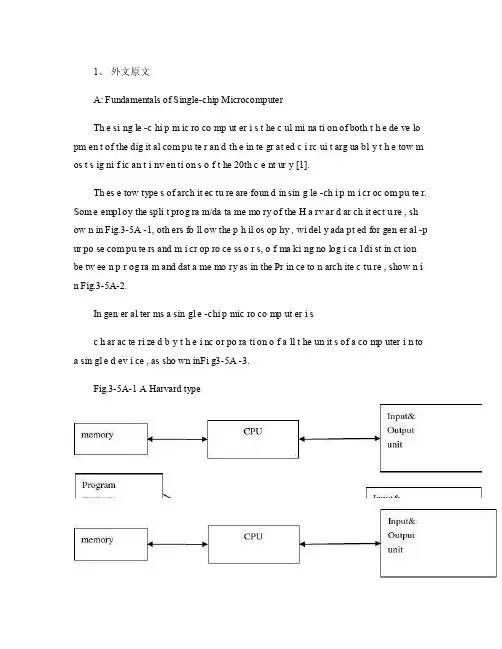
1、外文原文A: Fundamentals of Single-chip MicrocomputerTh e si ng le -c hi p m ic ro co mp ut er i s t he c ul mi na ti on of both t h e de ve lo pm en t of the dig it al com pu te r an d th e in te gr at ed c i rc ui t arg ua bl y t h e tow m os t s ig ni f ic an t i nv en ti on s o f t he 20th c e nt ur y [1].Th es e tow type s of arch it ec tu re are foun d in sin g le -ch i p m i cr oc om pu te r. Som e empl oy the spli t prog ra m/da ta me mo ry of the H a rv ar d ar ch it ect u re , sh ow n in Fig.3-5A -1, oth ers fo ll ow the p h il os op hy , wi del y ada pt ed for gen er al -p ur po se com pu te rs and m i cr op ro ce ss o r s, o f ma ki ng no log i ca l di st in ct ion be tw ee n p r og ra m and dat a me mo ry as in the Pr in ce to n arch ite c tu re , show n i n Fig.3-5A-2.In gen er al ter ms a sin gl e -chi p mic ro co mp ut er i sc h ar ac te ri zed b y t he i nc or po ra ti on of a ll t he un it s of a co mp uter i n to a sin gl e d ev i ce , as sho wn inFi g3-5A -3.Fig.3-5A-1 A Harvard typeFig.3-5A-2. A conventional Princeton computerFig3-5A-3. Principal features of a microcomputerRead only memory (ROM.R OM is usua ll y for the pe rm an ent,n o n-vo la ti le stor a ge of an app lic a ti on s pr og ra m .M an ym i cr oc om pu te rs and m are inte nd e d for high -v ol um e ap pl ic at ions a n d he nc e t h e eco n om ic al man uf act u re of th e de vic e s re qu ir es t h at t he cont en t s o f t he prog ra m me m or y be co mm it t ed perm a ne ntly d u ri ng the man ufa c tu re of ch ip s .Cl ea rl y, thi s im pl ie s a r i go ro us app ro ach to ROM cod e deve l op me nt sin ce cha ng es can not b e mad e afte r manu f a c tu re .Th is dev e lo pm en t proc ess may invo lv e e m ul at io n us in g aso ph is ti ca te d de ve lo pm en t sy ste m wit h a h a rd wa re emu la tio n cap ab il it y as w el l as the use o f po we rf ul s o ft wa re too ls.So me man uf act u re rs pro vi de add it io na l RO M opt i on s by i n cl ud in g in their ra n ge dev ic es wit h (or int en de d fo r use wit h u s er pro gr am ma ble me mo ry. Th e sim p le st of th es e is usu al ly d e vi ce whi ch can op er at e in a micro p ro ce ssor mod e by usi ng som e o f the inp ut /outp u t li ne s as an ad dr es s an d da ta b us fora c ce ss in g ex te rna l mem or y. Thi s t y pe of de vi ce can beh av ef u nc ti on al ly as th e sing le chip mi cr oc om pu te r from whi ch it is d e ri ve d al be it wit h re st ri ct ed I/O and a mod if ied ex te rn al c i rc ui t. The use of thes e d ev ic es is com mo n eve n in prod uc ti on c i rc ui ts wher e t he vo lu me does no tj us ti f y t h e d ev el o pm en t c osts o f c us to m o n -ch i p R OM [2];t he re c a n s ti ll bea s ignif i ca nt saving i n I /O and o th er c h ip s com pa re d to a conv en ti on al mi c ro pr oc es sor b a se d ci rc ui t. Mor e ex ac t re pl ace m en t fo r RO M dev i ce s ca n be o b ta in ed in th e fo rm of va ri an ts w it h 'p ig gy -b ack 'E P RO M(Er as ab le pro gr am ma bl e ROM s oc ke ts or dev ic e s with EPROM i n st ea d o f RO M 。
实用资料:电气工程专业课(电力类)翻译参考专业外语:Professional English电路(上) electrical circuit (I)电路(下) electrical circuit (II)金工实习 machinery practice电机(上) electrical machinery (I)电工实验与测试 electrical experiment & test电子综合实践 integrated electronic practice信号与系统 signal & system电子技术基础(模拟) fundamentals of electronic (analog)电磁场electromagnetic field电子技术实验 electronic experiment(I)电子辅助设计EDA Electronic Design Automatic(I)发电厂动力工程基础 Heat power engineering in generating plant企业管理 enterprise management电气主系统electrical system principle电力系统稳态/暂态分析 Steady-State/ Transient-State Analysis of Power System 电力系统继电保护 Power System Relaying Protection电力系统潮流计算机分析:Computer Analysis of Power Flow数字电子技术 Digital Electrical Technique微机原理 microcomputer principle电子技术基础(数字) fundamentals of electronic (digital)自动控制 automatic control theory电力系统分析 electric power system analysis电子技术基础实验electronic experiment(II)电气主系统课程设计 electrical system principle-course design电子辅助设计EDA Electronic Design Automatic(II)通信与计算机网络 communication & computer networks电力系统继电保护 electric power system relaying电力系统继电保护 Power System Protective Relaying电力系统远动技术electric power system remote protocol生产实习productive practice Technology继电保护课程设计 electric power system relaying-course design电力电子技术 power electronics电力电子技术基础:Fundamentals of Electronics Power Technology电力电子课程设计 Power electronics course design电力系统自动控制 electric power system control & automation高电压技术 High voltage engineering Technology变电站自动化 substation automation电力经济 electric power system economics电能质量控制 electric power quality control配电网自动化 distribution system automation电力系统新技术 new techniques on electric power system控制电机 electrical machine control调度自动化与能量管理 energy management & automation灵活交流输电系统 flexible AC transmission system计算机保护 computer protection电力系统电磁兼容 EMC in electric power system毕业实习graduation practice毕业设计graduation dissertation数字信号处理:Digital Signal Processing自动控制理论:Automatic Control Theory电气工程基础:Fundamentals of Electrical Engineering电磁场概论:Introduction to Electro-Magnetic Field计算机继电保护:Microcomputer-Based Relaying Protection电气设备的绝缘检测与故障诊断:Insulation Diagnostics and Troubl-Shooting for Electrical Installations电网规划:Power System Planning可编程控制器原理及应用:Principles of PLC (Programmable logic Controller) And Application电磁场数值计算:Numerical Computation of Electro-Magnetic Field电力系统继电保护:Relay Protection of Power System电力系统自动装置原理 The Principle of Electric Power System Automatic Equipment 电力通信系统及调度自动化:Power System Communication and Dispatching Automatic专业方向电气工程 Electrical Engineering电机与电器 Electric Machines and Electric Apparatus电力系统及其自动化 Power System and its Automation高电压与绝缘技术 High Voltage and Insulation Technology电力电子与电力传动 Power Electronics and Power Drives电工理论与新技术 Theory and New Technology of Electrical Engineering电子科学与技术 Electronics Science and Technology。
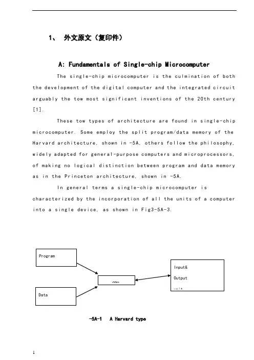
1、外文原文(复印件)A: Fundamentals of Single-chip MicrocomputerTh e si ng le-ch i p mi cr oc om pu ter is t he c ul mi nat i on o f bo th t h e d ev el op me nt o f th e d ig it al com p ut er an d t he int e gr at ed ci rc ui ta r gu ab ly th e t ow m os t s i gn if ic ant i nv en ti on s o f t h e 20t h c en tu ry[1].Th es e to w typ e s of a rc hi te ctu r e ar e fo un d i n s in gl e-ch ip m i cr oc om pu te r. So m e em pl oy t he sp l it p ro gr am/d ata me mo ry o f th e H a rv ar d ar ch it ect u re, sh ow n i n -5A, ot he rs fo ll ow th e ph i lo so ph y, w i de ly a da pt ed fo r g en er al-p ur pos e c om pu te rs an d m i cr op ro ce ss or s, o f m a ki ng no lo gi c al di st in ct io n b e tw ee n p ro gr am a n d da t a m em ory a s i n th e Pr in cet o n ar ch it ec tu re,sh ow n in-5A.In g en er al te r ms a s in gl e-chi p m ic ro co mp ut er i sc h ar ac te ri zed b y the i nc or po ra tio n of al l t he uni t s o f a co mp ut er i n to a s in gl e dev i ce, as s ho wn in Fi g3-5A-3.-5A-1 A Harvard type-5A. A conventional Princeton computerFig3-5A-3. Principal features of a microcomputerRead only memory (ROM).R OM i s u su al ly f or th e p er ma ne nt, n o n-vo la ti le s tor a ge o f an a pp lic a ti on s pr og ra m .M an ym i cr oc om pu te rs an d mi cr oc on tr ol le r s a re in t en de d fo r h ig h-v ol ume a p pl ic at io ns a nd h en ce t he e co nom i ca l ma nu fa ct ure of t he d ev ic es r e qu ir es t ha t the co nt en ts o f the pr og ra m me mo ry b e co mm it te dp e rm an en tl y d ur in g th e m an uf ac tu re o f c hi ps . Cl ear l y, th is im pl ie sa ri g or ou s a pp roa c h t o R OM co de d e ve lo pm en t s in ce c ha ng es ca nn otb e m ad e af te r man u fa ct ur e .T hi s d e ve lo pm en t pr oce s s ma y in vo lv e e m ul at io n us in g a s op hi st ic at ed deve lo pm en t sy st em w i th a ha rd wa re e m ul at io n ca pa bil i ty a s we ll a s th e u se of po we rf ul so ft wa re t oo ls.So me m an uf act u re rs p ro vi de ad d it io na l RO M opt i on s byi n cl ud in g i n th ei r ra ng e de vi ce s wi th (or i nt en de d fo r us e wi th) u s er pr og ra mm ab le m em or y. Th e s im p le st of th es e i s us ua ll y d ev ice w h ic h ca n op er ate in a m ic ro pr oce s so r mo de b y usi n g so me o f th e i n pu t/ou tp ut li ne s as a n ad dr es s an d da ta b us f or acc e ss in g e xt er na l m e mo ry. T hi s t ype o f d ev ic e c an b e ha ve fu nc ti on al l y a s t he si ng le c h ip mi cr oc om pu te r fr om wh ic h i t i s de ri ve d a lb eit w it h r es tr ic ted I/O an d a mo di fie d e xt er na l ci rcu i t. T he u se o f t h es e RO Ml es sd e vi ce s is c om mo n e ve n in p ro du ct io n c ir cu it s wh er e t he v ol um e do es n o t ju st if y th e d e ve lo pm en t co sts of c us to m on-ch i p RO M[2];t he re c a n st il l b e a si g ni fi ca nt s a vi ng in I/O a nd ot he r c hi ps co mp ar ed t o a c on ve nt io nal mi cr op ro ce ss or b as ed c ir cu it. M o re e xa ctr e pl ac em en t fo r RO M d ev ic es c an b e o bt ai ne d in t he f o rm o f va ri an ts w i th 'pi gg y-ba ck'EP RO M(Er as ab le p ro gr am ma bl e ROM)s oc ke ts o rd e vi ce s w it h EP ROM i ns te ad o f R OM 。
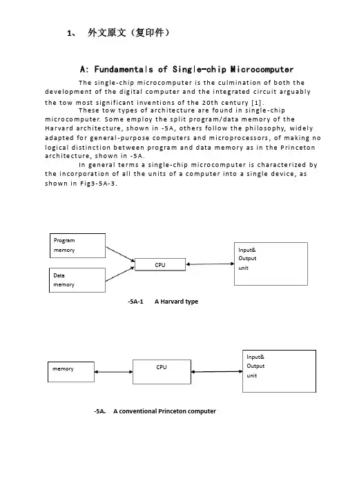
1、 外文原文(复印件)A: Fundamentals of Single-chip MicrocomputerT h e sin gle -ch ip mi c ro co m p u t e r is t h e cu lm in at io n of b ot h t h e d e ve lo p me nt of t h e d ig ita l co m p u t e r a n d t h e i nte g rated c ircu it a rgu ab l y t h e to w mo st s ign if i cant i nve nt i o n s of t h e 20t h c e nt u ry [1].T h ese to w t yp e s of arch ite ct u re are fo u n d in s in gle -ch ip m i cro co m p u te r. S o m e e mp l oy t h e sp l it p ro gra m /d at a m e m o r y of t h e H a r va rd arch ite ct u re , s h o wn in -5A , ot h e rs fo l lo w t h e p h i lo so p hy, wid e l y ad a p ted fo r ge n e ral -p u rp o se co m p u te rs an d m i cro p ro ce ss o rs , of m a kin g n o l o g i ca l d i st in ct i o n b et we e n p ro gra m an d d ata m e m o r y as in t h e P rin c eto n a rch ite ct u re , sh o wn in -5A.In ge n e ra l te r m s a s in g le -ch ip m ic ro co m p u t e r is ch a ra cte r ized b y t h e in co r p o rat io n of all t h e u n its of a co mp u te r into a s in gle d e vi ce , as s h o w n in F i g3-5A-3.-5A-1A Harvard type-5A. A conventional Princeton computerProgrammemory Datamemory CPU Input& Output unitmemoryCPU Input& Output unitResetInterruptsPowerFig3-5A-3. Principal features of a microcomputerRead only memory (ROM).RO M is u su a l l y fo r t h e p e r m an e nt , n o n -vo lat i le sto rage of an ap p l i cat io n s p ro g ram .M a ny m i c ro co m p u te rs a n d m i cro co nt ro l le rs are inte n d ed fo r h i gh -vo lu m e ap p l i cat io n s a n d h e n ce t h e e co n o m i cal man u fa c t u re of t h e d e vi ces re q u ires t h at t h e co nt e nts of t h e p ro gra m me mo r y b e co mm i ed p e r m a n e nt l y d u r in g t h e m a n u fa ct u re of c h ip s . C lea rl y, t h i s imp l ies a r i go ro u s ap p ro a ch to ROM co d e d e ve lo p m e nt s in ce ch an ges can n o t b e mad e af te r m an u fa ct u re .T h i s d e ve l o p m e nt p ro ces s m ay i nvo l ve e mu l at i o n u sin g a so p h ist icated d e ve lo p m e nt syste m wit h a h ard wa re e mu l at i o n capab i l it y as we ll as t h e u s e of p o we rf u l sof t war e to o l s.So m e m an u fa ct u re rs p ro vi d e ad d it i o n a l ROM o p t io n s b y in clu d in g in t h e i r ran ge d e v ic es w it h (o r inte n d ed fo r u s e wit h ) u se r p ro g ram m a b le m e mo r y. T h e s im p lest of t h e se i s u su a l l y d e v i ce wh i ch can o p e rat e in a m i cro p ro ce s so r mo d e b y u s in g s o m e of t h e in p u t /o u t p u t l in es as an ad d res s a n d d ata b u s fo r a cc es sin g exte rn a l m e m o r y. T h is t yp e o f d e vi ce can b e h ave f u n ct i o n al l y as t h e s in gle ch ip m i cro co m p u t e r f ro m wh i ch it i s d e ri ved a lb e it wit h re st r icted I/O an d a m o d if ied exte rn a l c ircu it. T h e u s e of t h e se RO M le ss d e vi ces i s co mmo n e ve n in p ro d u ct io n circu i ts wh e re t h e vo lu m e d o e s n ot ju st if y t h e d e ve lo p m e nt co sts of cu sto m o n -ch ip ROM [2];t h e re ca n st i ll b e a si gn if i cant sav in g in I/O an d o t h e r ch ip s co m pared to a External Timing components System clock Timer/ Counter Serial I/O Prarallel I/O RAM ROMCPUco nve nt io n al m i c ro p ro ces so r b ased circ u it. M o re exa ct re p l a ce m e nt fo rRO M d e v ice s can b e o b tain ed in t h e fo rm of va ria nts w it h 'p i g g y-b a c k'E P ROM(E rasab le p ro gramm ab le ROM )s o cket s o r d e v ice s w it h E P ROMin stead of ROM 。
西华大学毕业设计外文资料翻译附录:外文资料翻译外文资料原文:A Virtual Environment for Protective Relaying Evaluation and TestingA. P. Sakis Meliopoulos and George J. CokkinidesAbstract—Protective relaying is a fundamental discipline of power system engineering. At Georgia Tech, we offer three courses that cover protective relaying: an undergraduate course that devotes one-third of the semester on relaying, a graduate courseentitled “Power System Protection,” and a three-and-a-half-day short course for practicing engineers. To maximize student understanding and training on the concepts,theory, and technology associated with protective relaying, we have developed a number of educational tools, all wrapped in a virtual environment. The virtual environment includes a) a power system simulator, b) a simulator of instrumentation for protective relaying with visualization and animation modules, c) specific protective relay models with visualization and animation modules, and d) interfaces to hardware so that testing of actual relaying equipment can be per formed. We refer to this set of software as the “virtual power system.” The virtual power system permits the in-depth coverage of the protective relaying concepts in minimum time and maximizes student understanding. The tool is not used in a passive way. Indeed, the students actively participate with well-designed projects such as a) design and implementation of multifunctional relays, b) relay testing for specific disturbances, etc. The paper describes the virtual power system organization and “engines,” s uch as solver, visualization, and animation of protective relays, etc. It also discusses the utilization of this tool in the courses via specific application examples and student assignments.Index Terms—Algebraic companion form, animation, relaying,time-domain simulation, visualization.I. INTRODUCTIONR ELAYING has always played a very important role in the security and reliability of electric power systems. As the technology advances, relaying has become more sophisticated with many different options for improved protection of the system. It is indisputable that relaying has made significant advances with dramatic beneficial effects on the safety of systems and protection of equipment. Yet, because of the complexity of the system and multiplicity of competing factors, relaying is a challenging discipline.Despite all of the advances in the field, unintended relay operations (misoperations) do occur. Many events of outages and blackouts can be attributed to inappropriate relayingsettings, unanticipated system conditions, and inappropriate selection of instrument transformers. Design of relaying schemes strives to anticipate all possible conditions for the purpose of avoiding undesirable operations. Practicing relay engineers utilize a two-step procedure to minimize the possibility of such events. First, in the design phase, comprehensive analyses are utilized to determine the best relaying schemes and settings. Second, if such an event occurs, an exhaustive post-mortem analysis is performed to reveal the roo t cause of the event and what “was missed” in the design phase. The post-mortem analysis of these events is facilitated with the existing technology of disturbance recordings (via fault disturbance recorders or embedded in numerical relays). This process results in accumulation of experience that passes from one generation of engineers to the next.An important challenge for educators is the training of students to become effective protective relaying engineers. Students must be provided with an understanding of relaying technology that encompasses the multiplicity of the relaying functions, communications, protocols, and automation. In addition, a deep understanding of power system operation and behavior during disturbances is necessary for correct relayin g applications. In today’s crowded curricula, the challenge is to achieve this training within a very short period of time, for example, one semester. This paper presents an approach to meet this challenge. Specifically, we propose the concept of the virtual power system for the purpose of teaching students the complex topic of protective relaying within a short period of time.The virtual power system approach is possible because of two factors: a) recent developments in software engineering and visualization of power system dynamic responses, and b) the new generation of power system digital-object-oriented relays. Specifically, it is possible to integrate simulation of the power system, visualization, and animation of relay response and relay testing within a virtual environment. This approach permits students to study complex operation of power systems and simultaneously observe relay response with precision and in a short time.The paper is organized as follows: First, a brief description of the virtual power system is provided. Next, the mathematical models to enable the features of the virtual power system are presented together with the modeling approach for relays and relay instrumentation. Finally, few samples of applications of this tool for educational purposes are presented.II. VIRTUAL POWER SYSTEMThe virtual power system integrates a number of application software in a multitasking environment via a unified graphical user interface. The application software includes a) a dynamic power system simulator, b) relay objects, c) relay instrumentation objects, and d)animation and visualization objects. The virtual power system has the following features:1) continuous time-domain simulation of the system under study;2) ability to modify (or fault) the system under study during the simulation, and immediately observe the effects of thechanges;3) advanced output data visualization options such as animated 2-D or 3-D displays that illustrate the operation of any device in the system under study.The above properties are fundamental for a virtual environment intended for the study of protective relaying. The first property guarantees the uninterrupted operation of the system under study in the same way as in a physical laboratory: once a system has been assembled, it will continue to operate. The second property guarantees the ability to connect and disconnect devices into the system without interrupting the simulation of the system or to apply disturbances such as a fault. This property duplicates the capability of physical laboratories where one can connect a component to the physical system and observe the reaction immediately (e.g., connecting a new relay to the system and observing the operation of the protective relaying logic, applying a disturbance and observing the transients as well as the relay logic transients, etc.). The third property duplicates the ability to observe the simulated system operation, in a similar way as in a physical laboratory. Unlike the physical laboratory where one cannot observe the internal operation of a relay, motor, etc., the virtual power system has the capability to provide a visualization and animation of the internal “workings” of a relay, motor, etc. This capability to animate and visualize the internal “workings” o f a relay, an instrumentation channel, or any other device has substantial educational value.The virtual power system implementation is based on the MS Windows multidocument-viewarchitecture. Each document object constructs a single solver object, which handles the simulation computations. The simulated system is represented by a set of objects—one for each system device (i.e. generators, motors, transmission lines, relays, etc). The document object can generate any number of view window objects. Two basic view classes are available: a) schematic views and b) result visualization views. Schematic view objects allow the user to define the simulated system connectivity graphically, by manipulating a single line diagram using the mouse. Result visualization views allow the user to observe calculated results in a variety of ways. Several types of result visualization views are supported and will be discussed later.Fig. 1 illustrates the organization of device objects, network solver, and view objects and their interactions. The network solver object is the basic engine that provides the time-domain solution of the device operating conditions. To maintain object orientation, each device isrepresented with a generalized mathematical model of a specific structure, the algebraic companion form (ACF). The mathematics of the algebraic companion form are described in the next section. Implementationwise, the network solver is an independent background computational thread, allowing both schematic editor and visualization views to be active during the simulation. The network solver continuously updates the operating states of the devices and “feeds” all other applications, such as visualization views,etc.The network solver speed is user selected, thus allowing speeding-up or slowing-down the visualization and animation speed. The multitasking environment permits system topology changes, device parameter changes, or connection of new devices (motors, faults) to the system during the simulation. In this way, the user can immediately observe the system response in the visualization views.The network solver interfaces with the device objects. This interface requires at minimum three virtual functions:Initialization: The solver calls this function once before the simulation starts. It initializes all device-dependent parameters and models needed during the simulation.Reinitialization: The solver calls this function any time the user modifies any device parameter. Its function is similar to the initialization virtual function.Time step: The solver calls this function at every time step of the time-domain simulation. It transfers the solution from the previous time step to the device object and updates the algebraic companion form of the device for the next time step (see next section “network solver.”)In addition to the above functions, a device object has a set of virtual functions comprising the schematic module interface. These functions allow the user to manipulate the device within the schematic editor graphical user interface. Specifically,the device diagram can be moved, resized, and copied using the mouse. Also, a function is included in this set, which implements a device parameter editing dialog window which “pops-up” by double clicking on the device icon. Furthermore,the schematic module interface allows for device icons that reflect the device status. For example, a breaker schematic icon can be implemented to indicate the breaker status.Finally, each device class (or a group of device classes) may optionally include a visualization module, consisting of a set of virtual functions that handle the visualization and animation output. The visualization module interface allows for both two-dimensional (2-D) and three-dimensional (3-D) graphics. Presently, 2-D output is implemented via the Windows graphical device interface (GDI) standard. The 3-D output is implemented using the opengraphics library (OpenGL). Both 2-D and 3-D outputs generate animated displays, which are dynamically updated by the network solver to reflect the latest device state. The potential applications of 2-D or 3-D animated visualization objects are only limited by the imagination of the developer. These objects can generate photorealistic renderings of electromechanical components that clearly illustrate their internal operation and can be viewed from any desired perspective,slowed down, or paused for better observation.III. NETWORK SOLVERAny power system device is described with a set of algebraicdifferential-integral equations. These equations are obtained directlyfrom the physical construction of the device. It is alwayspossible to cast these equations in the following general formNote that this form includes two sets of equations, which arenamed external equations and internal equations, respectively.The terminal currents appear only in the external equations.Similarly, the device states consist of two sets: external states[i.e., terminal voltages, v(t)] and internal states [i.e. y(t)]. Theset of (1) is consistent in the sense that the number of externalstates and the number of internal states equals the number of externaland internal equations, respectively.Note that (1) may contain linear and nonlinear terms. Equation(1) is quadratized (i.e., it is converted into a set of quadraticequations by introducing a series of intermediate variables and expressing the nonlinear components in terms of a series of quadratic terms). The resulting equations are integrated using a suitable numerical integration method. Assuming an integration time step h, the result of the integration is given with a second-order equation of the formwhere , are past history functions.Equation (2) is referred to as the algebraic companion form (ACF) of the device model. Note that this form is a generalizationof the resistive companion form (RCF) that is used by the EMTP [3]. The difference is that the RCF is a linear model that represents a linearized equivalent of the device while the ACF is quadratic and represents the detailed model of the device.The network solution is ob tained by application of Kirchoff’s current law at each node of the system (connectivity constraints). This procedure results in the set of (3). To these equations, the internal equations are appended resulting to the following set of equations:(3)internal equations of all devices (4)where is a component incidence matrix withif node of component is connected to node otherwise is the vector of terminal currents of component k.Note that (3) correspond one-to-one with the external system states while (4) correspond one-to-one with the internal system states. The vector of component k terminal voltages is related to the nodal voltage vector by(5)Upon substitution of device (2), the set of (3) and (4)become a set of quadratic equations (6)where x(t) is the vector of all external and internal system states.These equations are solved using Newton’s method. Specifically,the solution is given by the following expression(7)where is the Jacobian matrix of (6) and are the values ofthe state variables at the previous iteration.IV. RELAY INSTRUMENTATION MODELINGRelays and, in general, IEDs use a system of instrument transformers to scale the power system voltages and currents into instrumentation level voltages and currents. Standard instrumentation level voltages and currents are 67 V or 115 V and 5 A, respectively. These standards were established many years ago to accommodate the electromechanical relays. Today, the instrument transformers are still in use but because modern relays (and IEDs) operate at much lower voltages, it is necessary to apply an additional transformation to the new standard voltages of 10 or 2 V. This means that the modern instrumentation channel consists of typically two transformations and additional wiring and possibly burdens. Fig. 2 illustrates typical instrumentation channels, a voltage channel and a current channel. Note that each component of the instrumentation channel will introduce an error. Of importance is the net error introduced by all of the components of the instrumentation channel. The overallerror can be defined as follows. Let the voltage or current at the power system be and , respectively. An ideal instrumentation channel will generate a waveform at the output of the channel that will be an exact replica of the waveform at the power system. If the nominal transformation ratio is and for the voltage and current instrumentation channels, respectively, then the output of an “ideal” system and the instrumentation channel error will bewhere the subscript “out” refers to the actual output of the instrumentation channel. The error waveforms can be analyzed to provide the rms value of the error, the phase error, etc.Any relaying course should include the study of instrumentation channels. The virtual power system is used to study the instrumentation error by including an appropriate model of the entire instrumentation channel. It is important to model the saturation characteristics of CTs and PTs, resonant circuits of CCVTs, etc. (see [6]). In the virtual power system, models of instrumentation channel components have been developed. The resulting integrated model provides, with precision, the instrumentation channel error.With the use of animation methods, one can study the evolution of instrumentation errors during transients as well as normal operation.V. PROTECTIVE RELAY MODELINGToday, all new relays are numerical relays. These types of relays can be easily modeled within the virtual power system. Consider, for example, a directional relay. The operation ofthis relay is based on the phase angle between the polarizing voltage and the current. Modeling of this relay then requires that the phase angle between the polarizing voltage and the current be computed. For this purpose, as the power system simulation progresses, the relay model retrieves the instantaneous values of the polarizing voltage and the current. A Fourier transform is applied to the retrieved data (a running time Fourier transform over a user-specified time window). The result will be the phasors of the polarizing voltage and current from which the phase angles are retrieved. The directional element of the relay will trip if the phase angle difference is within the operating region. It should be also self understood that if the relay to be modeled has filters, these filters can be also included in the model.It is important that students be also involved in the design of numerical relays. A typical semester project is to define the functionality of a specific relay and a set of test cases. The student assignment is to develop the code that will mimic the operation of the relay and demonstrate its correct operation for the test cases.The new technology of the virtual power system offers another more practical way to model relays. The virtual power system uses object-oriented programming. As such, it is an open architecture and can accept dynamic link libraries of third parties. A natural extension of the work reported in this paper is to use this feature to interface with commercially available digital “relays.” The word “relay” is in quotation marks to indicate that the relay is simply a digital program that takes inputs of voltages and currents, performs an analysis of these data, applies logic, and issues a decision. This program is an object and can be converted into a dynamic link library. If this DLL is “linked” with the virtual power system, in the sense that the inputs come from the virtual power system, then the specific relay can be evaluated within the virtual environment. The technology for this approach is presently available. Yet, our experience is that relay manufacturers are not presently perceptive in making their “relay” objects available as DLLs that can be interfaced with third-party software.VI. APPLICATIONSThe described virtual environment has been used in a variety of educational assignments. The possible uses are only limited by the imagination of the educator. In this section, we describe a small number of educational application examples.Figs. 3 and 4 illustrate an exercise of studying instrumentation channel performance. Fig. 3 illustrates an example integrated model of a simple power system and the model of an instrumentation channel (voltage). The instrumentation channel consists of a PT, a length of control cable, an attenuator, and an A/D converter (Fig. 3 illustrates the icons of thesecomponents and their interconnection). Fig. 4 illustrates two waveforms: the voltage of phase A of the power system when it is experiencing a fault and the error of the instrumentation channel. The upper part of the figure illustrates the actual voltage of Phase A and the output of the instrumentation channel (multiplied by the nominal transformation ratio). The two traces are quite close. The lower part of the figure illustrates the error between the two waveforms of the upper part of the figure. The two curves illustrate the normalized error at the input of the A/D converter and at the output of the A/D converter. The figure is self-explanatory and a substantial error occurs during the transient of the fault. When the transients subside, the error of the instrumentation channel is relatively small. The intention of this exercise is to study the effects of different parameters of the instrumentation channel.For example, the students can change the length of the control cable and observe the impact on the error. Or in case of a current channel, they can observe the effects of CT saturation on the error of the instrumentation channel, etc.Fig. 5 illustrates the basics of an example application of the virtual power system for visualization and animation of a modified impedance relay. The example system consists of a generator, a transmission line, a step-down transformer, a passive electric load (constant impedance load), an induction motor, and a mechanical load of the motor (fan). A modified distance relay (mho relay) monitors the transmission line. The operation of this relay is based on the apparent impedance that the relay “sees” and the trajectory of this impedance.The visualization object of this relay displays what the relay “sees” during a disturbance in the system and superimposes this information on the relay settings. Typical examples are illustrated in Figs. 6 and 7. The relay monitors the three-phase voltages and currents at the point of its application. The animation model retrieves the information that the relay monitors from the simulator at each time step. Subsequently, it computes the phasors of the voltages and currents as well as the sequence components of these voltages and currents. Fig. 6 illustrates a 2-D visualization of the operation of this relay over a period that encompasses a combined event of an induction motor startup followed by a single-phase fault on the high-voltage side of the transformer. (This example demonstrates the flexibility of the tool to generate composite events that may lead to very interesting responses of the protective relays). The left-hand side of the 2-Dvisualization shows the voltages and currents “seen” by the relay(the snapshot is after the fault has been cleared). The graph also shows the trajectory (history) of the impedance “seen” by the relay. The graph shows the trajectory “seen” over a user-specified time interval preceding present time. The impedance trajectory is superimposed on the trip characteristics of this relay. In this case, the impedance trajectory does not visit thetrip “region” of the relay.Fig. 7 provides the recorded impedance trajectory for the combined event of an induction motor startup followed by a three-phase fault near the low-voltage bus of the transformer. The impedance trajectory is superimposed on the trip characteristics of this relay. In this case, the impedance trajectory does visit the trip “region” of the relay. This example can be extended to more advanced topics. For example, the animated display may also include stability limits for the “swing” of the generator. For this purpose, the stability limits for the particular condition must be computed and displayed.This exercise can be the topic of a term project.Another important protective relaying example is the differential relay. In this example, we present the animated operation of a differential relay scheme for a delta-wye connected transformer with tap changing under load. The example system is shown in Fig. 8. It consists of an equivalent source, a transmission line, a 30-MVA delta-wye connected transformer, a distribution line, and an electric load. A transformer differential relay Fig. 7. Animation of a mho relay for a three phase fault on the 13.8-kV bus. is protecting the transformer. The differential relay has as inputs the transformer terminal currents. A specific implementation of a differential relay visualization is shown in Fig. 9 based on the electromechanical equivalent relay. Note that the 2-D visualization shows t he “operating” coils and “restraining” coils and the currents that flow in these coils at any instant of time. Instantaneous values, rms values, and phasor displays are displayed. Fig. 9 illustrates one snapshot of the system. In reality, as the system operation progresses, this figure is continuously updated, providing an animation effect. The system may operate under steady-state or under transient conditions. The effects of tap changing on the operation of the relay are demonstrated. The importance of this animation module is that one can study the effects of various parameters and phenomena on the operation of the relay. Examples are: a) effects of tap setting. The differential relay settings are typically selected for the nominal tap setting. As the tap setting changes under load, the current in the operating coil changes and may be nonzero even under normal operating conditions. It is very easy to change the tap setting andobserve the operation of the relay in an animated fashion. It is also easy to observe the operation of the relay during a through fault for different values of tap settings. Thus, this tool is very useful in determining the optimal level of percent restraint for the relay. b) effects of inrush currents. One can perform energization simulations of the transformer by various types of breaker-closing schemes. Since the transformer model includes the nonlinear magnetization model of the transformer core, the magnetization inrush currents will appear in the terminals of the transformer and, therefore, in the differential relay. The display of Fig. 9 provides a full picture of the evolutionof the electric currents. One can study the effects of inrush currents by bypassing the even harmonic filters as well as by implementing a number of harmonic filters and observing the effectiveness of the filters. It is important to note that the phenomena involved are very complex, yet a student can study these phenomena indepth and in very short time with the aid of animation and visualization methods.The virtual power system has been also used for testing of physical relays. This application is quite simple. The virtual power system has the capability to export voltage and current waveforms of any event and for any user-selected time period in COMTRADE format. Then, the COMTRADE file is fed into commercial equipment that generates the actual voltages and currents and feeds them into the physical relays. The actual response of the relays is then observed. This application was performed on the premises of a utility with limited access to students.Recently, a major relay manufacturer (SEL) has donated equipment to Georgia Tech and we are in the process of setting up the laboratory for routine use of this function by students. There are numerous other applications of the proposed virtual power system. The pedagogical objective is to instill a deep understanding of protective relaying concepts and problems in the very short time of one semester. The effectiveness of the proposed approach increases as new examples are generated and stored in the database.Aclassical example that demonstrates the effectiveness of the virtual power system is the issue of sympathetic tripping. Usually, this topic requires several lectures and long examples. With the virtual power system, one can very thoroughly teach the concept of sympathetic tripping within onelecture. For example, a simple system with mutually coupled lines can be prepared, with relays at the ends of all lines. Then with a fault in one line, the relays of the healthy line can be visualized and animated. The students can observe that the relays of the healthy line “see” zero-sequence current induced by the fault on another line. And more important, the students can make changes to the designs of the lines and observe the relative effect of design parameters on induced voltages and currents, etc.VII. CONCLUSIONThis paper has discussed and presented the virtual power system and its application for visualization and animation of protective relaying. The virtual power system has proved to be a valuable tool in the instruction of protective relaying courses. It is also an excellent tool for assigning term projects on various aspects of protective relaying. One important feature of the tool is that the user can apply disturbances to the system while the system operates (i.e., faults, load shedding, motor start-up, etc.). The response of the relays is instantaneously observed.。
电气工程的外文文献(及翻译)文献一:Electric power consumption prediction model based on grey theory optimized by genetic algorithms本文介绍了一种基于混合灰色理论与遗传算法优化的电力消耗预测模型。
该模型使用时间序列数据来建立模型,并使用灰色理论来解决数据的不确定性问题。
通过遗传算法的优化,模型能够更好地预测电力消耗,并取得了优异的预测结果。
此模型可以在大规模电力网络中使用,并具有较高的可行性和可靠性。
文献二:Intelligent control for energy-efficient operation of electric motors本文研究了一种智能控制方法,用于电动机的节能运行。
该方法提供了一种更高效的控制策略,使电动机能够在不同负载条件下以较低的功率运行。
该智能控制使用模糊逻辑方法来确定最佳的控制参数,并使用遗传算法来优化参数。
实验结果表明,该智能控制方法可以显著降低电动机的能耗,节省电能。
文献三:Fault diagnosis system for power transformers based on dissolved gas analysis本文介绍了一种基于溶解气体分析的电力变压器故障诊断系统。
通过对变压器油中的气体样品进行分析,可以检测和诊断变压器内部存在的故障类型。
该系统使用人工神经网络模型来对气体分析数据进行处理和分类。
实验结果表明,该系统可以准确地检测和诊断变压器的故障,并有助于实现有效的维护和管理。
文献四:Power quality improvement using series active filter based on iterative learning control technique本文研究了一种基于迭代研究控制技术的串联有源滤波器用于电能质量改善的方法。

毕业设计(论文)外文文献译文及原文Application of the Power Flow Calculation Method to Islanding Micro GridsY.H. Liu. Z.Q. Wu, S.J Lin, N. P. BrandonAbstract:Most existing power flow calculation methods use a swing bus as a reference node for the whole system Increasingly. new distributed generation resources (DGRs) are being added to the grid. Sometimes, local demand or failure of the grid can result in independent micro-grids forming, which are known as 'islanding' systems Howcver. current DGRs are often limited such that there is no single DGR which can balance the power demand and stabilize the frequency of the micro-grid, meaning that there is no swing bus from which the microgrid can bemanaged. According to existing research. a DGR coupled with a dcdicated cnergy storage .system and suitable control stratcgy (here termed a distributcd generation (DG system) has the ability to adjust its output. This means that a DG system can respond dynamically to grid events. This means that a DG .system can rcspond dynamically to grid events. In this paper. a new power flow calculation method (based on Newton-Raphson power flow solution) with good convergence is proposed that can accommodate the lack of a swing bus in an islanding system. This addresses power flow results and the frequency ofthe whole system. The method proposed is discussed in detail with cxamples of diffcrent DG systems with various adjustment coefficients and load models.The results arc compared with those of a traditional power flow calculation mcthod based around the use of a swing bus. In conclusion, this paper shows that the improved method is more apprpriate for islanding systems with mesh topology and for micro-grid management wihtno swing bus.Index Terms--Distributed Generation; Islanding; Micro Grid; Power Flow Calculation; Power SystemⅠ.NOMENCLATUREA. Indexesi,j numbef of node ;B. Constantsn number of nods of the system;m number of non-power-source nodes in the system;Ai percentage coefficient of constant impedance load in a compound load modeBi percentage coefficient ofconstant current load in a compound load model;Ci percentage coefficient of constant power load in a compound load model;错误!未找到引用源。
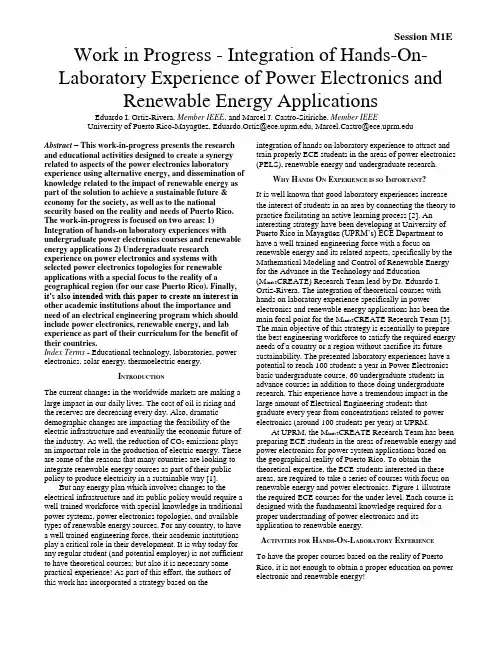
Session M1E Work in Progress - Integration of Hands-On- Laboratory Experience of Power Electronics and Renewable Energy ApplicationsEduardo I. Ortiz-Rivera, Member IEEE, and Marcel J. Castro-Sitiriche, Member IEEEUniversity of Puerto Rico-Mayagüez, Eduardo.Ortiz@, Marcel.Castro@Abstract– This work-in-progress presents the research and educational activities designed to create a synergy related to aspects of the power electronics laboratory experience using alternative energy, and dissemination of knowledge related to the impact of renewable energy as part of the solution to achieve a sustainable future & economy for the society, as well as to the national security based on the reality and needs of Puerto Rico. The work-in-progress is focused on two areas: 1) Integration of hands-on laboratory experiences with undergraduate power electronics courses and renewable energy applications 2) Undergraduate research experience on power electronics and systems with selected power electronics topologies for renewable applications with a special focus to the reality of a geographical region (for our case Puerto Rico). Finally, it’s also intended with this paper to create an interest in other academic institutions about the importance and need of an electrical engineering program which should include power electronics, renewable energy, and lab experience as part of their curriculum for the benefit of their countries.Index Terms - Educational technology, laboratories, power electronics, solar energy, thermoelectric energy.I NTRODUCTIONThe current changes in the worldwide markets are making a large impact in our daily lives. The cost of oil is rising and the reserves are decreasing every day. Also, dramatic demographic changes are impacting the feasibility of the electric infrastructure and eventually the economic future of the industry. As well, the reduction of CO2 emissions plays an important role in the production of electric energy. These are some of the reasons that many countries are looking to integrate renewable energy sources as part of their public policy to produce electricity in a sustainable way [1].But any energy plan which involves changes to the electrical infrastructure and its public policy would require a well trained workforce with special knowledge in traditional power systems, power electronics topologies, and available types of renewable energy sources. For any country, to have a well trained engineering force, their academic institutions play a critical role in their development. It is why today for any regular student (and potential employer) is not sufficient to have theoretical courses; but also it is necessary some practical experience! As part of this effort, the authors of this work has incorporated a strategy based on the integration of hands on laboratory experience to attract and train properly ECE students in the areas of power electronics (PELS), renewable energy and undergraduate research.W HY H ANDS O N E XPERIENCE IS SO I MPORTANT?It is well known that good laboratory experiences increase the interest of students in an area by connecting the theory to practice facilitating an active learning process [2]. An interesting strategy have been developing at University of Puerto Rico in Mayagüez (UPRM’s) ECE Departm ent to have a well trained engineering force with a focus on renewable energy and its related aspects, specifically by the Mathematical Modeling and Control of Renewable Energy for the Advance in the Technology and Education(M inds2CREATE) Research Team lead by Dr. Eduardo I. Ortiz-Rivera. The integration of theoretical courses with hands on laboratory experience specifically in power electronics and renewable energy applications has been the main focal point for the M inds2CREATE Research Team [3]. The main objective of this strategy is essentially to prepare the best engineering workforce to satisfy the required energy needs of a country or a region without sacrifice its future sustainability. The presented laboratory experiences have a potential to reach 100 students a year in Power Electronics basic undergraduate course, 60 undergraduate students in advance courses in addition to those doing undergraduate research. This experience have a tremendous impact in the large amount of Electrical Engineering students that graduate every year from concentrations related to power electronics (around 100 students per year) at UPRM.At UPRM, the M inds2CREATE Research Team has been preparing ECE students in the areas of renewable energy and power electronics for power system applications based on the geographical reality of Puerto Rico. To obtain the theoretical expertise, the ECE students interested in these areas, are required to take a series of courses with focus on renewable energy and power electronics. Figure 1 illustrate the required ECE courses for the under level. Each course is designed with the fundamental knowledge required for a proper understanding of power electronics and its application to renewable energy.A CTIVITIES FOR H ANDS-O N-L ABORATORY E XPERIENCETo have the proper courses based on the reality of Puerto Rico, it is not enough to obtain a proper education on power electronic and renewable energy!Session M1E Experimental Set-upFIGURE 1PELS U NDERGRADUATE O PTION WITH FOCUS ON R ENEWABLE E NERGY. That’s why, the integration of a hands on laboratory experiences to these courses is fundamental to attract new students and increase their interest to do research in engineering. In the long run, these steps are the ones that provide the base for advance graduate education. The activities related to hands on laboratory experience are incorporated with other educational components such as theory, simulations, and real-life engineering problems offered in the courses. An example of the experiments for the students hands-on-experience is decribed:1) Electrical characterization of proton exchange fuel cells For this experimental work, the student will use a low power PEM fuel cell interconnected with a dc-dc converter and a variable resistive load. It is required that the student should learn how to use a PEM fuel cell, design the required components for the dc-dc converter, simulate and construct a prototype to control the power and current by a fuel cell. 2) Mathematical modeling of PV modules for MPPT control This experiment involve concepts related to optimal control and the characterization of PVM’s using nonlinear models. For this task the student will learn how to understand a PV datasheet and to use this data to charaterize a solar panel. The theoretical values will be compared with the PVM experimental values using a software tool previsouly designed [1]. Finally, the student will connect the PVM’s toa boost converter to extract the PVM’s maximum power.3) Desing and prototype of a three phase Z-Source inverter For the realization of this experiment, it is required that the student should understand concepts like three phase systems, Pulse-Width-Modulation, Z-source, and inverters. To design the inverter, the student is required to use software tools like PSIM, SABER, Matlab, etc. At the Power Electronics Systems (PELS) lab, the students will construct a prototypeFIGURE 2E LECTRICAL C HARACTERIZATION AND C ONTROL OF PEM F UEL C ELL.will appeal to a wide range of areas at the University of Puerto Rico. Some of the advantages to study different types of renewable energies in Puerto Rico are excellent tropical weather conditions, constant wind conditions in the mountain regions, year-round sunny conditions, and all of them in a single place. Finally, this project has been successful given that Puerto Rico has an excellent location in the Caribbean, active research of new technologies related to renewable energy, an excellent place for the education of engineers, and interest of the students for business opportunities in the island as future entrepreneurs.P ROJECT S TATUSThe research group has successfully disseminated the work through 5 publications in various journals and conferences. Twelve undergraduate students have been doing hands-on laboratory based research during the past year. Currently, we are bringing together representatives from the various industries related to renewable energy to identify specific workforce skills. Specifically, we are in the process of convening an advisory board group charged with refining and implementing the process for involving a wider collaboration between the industry and the academy at PR. This board will make recommendations to the group related to areas of need, potential for innovation, funding sources and crucial long term partnerships.A CKNOWLEDGMENTThe authors gratefully acknowledge the contributions of all the members that belong to the Mathematical Modeling and Control of Renewable Energies for Advance Technology & Education (M inds2CREATE) Research Team at UPRM.including topology selection, heat sink, insulated-gate bipolar transistor (IGBT) selection & transformer/inductor construction [3].E XPECTEDF UTURE FOR THE S TUDENTS AND P UERTO R ICOIt is expected that at the end of the student academic career, the student will have a breadth of relevant power electronic topologies useful for renewable sources, knowledge in the characterization of the available renewable energies in the geographic region of Puerto Rico, familiarity about public policy related to energy and the agencies for their use & regulation with their societal/economical issues, all of whichM1E-2进行中的工程——电力电子技术和可再生能源实验课程的一体化摘要这个正在进行的工作展现了研究工作和教育活动在利用可替代能源的电力电子实验室和可再生能源作为未来经济和社会获得可持续发展的解决方案和基于波多黎各国家实际需要的重要影响的散布推广。
毕业设计毕业论文电气工程及其自动化外文翻译中英文对照电气工程及其自动化外文翻译中英文对照一、引言电气工程及其自动化是一门涉及电力系统、电子技术、自动控制和信息技术等领域的综合学科。
本文将翻译一篇关于电气工程及其自动化的外文文献,并提供中英文对照。
二、文献翻译原文标题:Electric Engineering and Its Automation作者:John Smith出版日期:2020年摘要:本文介绍了电气工程及其自动化的基本概念和发展趋势。
首先,介绍了电气工程的定义和范围。
其次,探讨了电气工程在能源领域的应用,包括电力系统的设计和运行。
然后,介绍了电气工程在电子技术领域的重要性,包括电子设备的设计和制造。
最后,讨论了电气工程与自动控制和信息技术的结合,以及其在工业自动化和智能化领域的应用。
1. 介绍电气工程是一门研究电力系统和电子技术的学科,涉及发电、输电、配电和用电等方面。
电气工程的发展与电力工业的发展密切相关。
随着电力需求的增长和电子技术的进步,电气工程的重要性日益凸显。
2. 电气工程在能源领域的应用电气工程在能源领域的应用主要包括电力系统的设计和运行。
电力系统是由发电厂、输电线路、变电站和配电网络等组成的。
电气工程师负责设计和维护这些设施,以确保电力的可靠供应。
3. 电气工程在电子技术领域的重要性电气工程在电子技术领域的重要性体现在电子设备的设计和制造上。
电子设备包括电脑、手机、电视等消费电子产品,以及工业自动化设备等。
电气工程师需要掌握电子电路设计和数字信号处理等技术,以开发出高性能的电子设备。
4. 电气工程与自动控制和信息技术的结合电气工程与自动控制和信息技术的结合是电气工程及其自动化的核心内容。
自动控制技术可以应用于电力系统的运行和电子设备的控制,以提高系统的稳定性和效率。
信息技术则可以用于数据采集、处理和传输,实现对电力系统和电子设备的远程监控和管理。
5. 电气工程在工业自动化和智能化领域的应用电气工程在工业自动化和智能化领域的应用越来越广泛。
名词解释:1.集成电路Integrated circuit2.可编程逻辑控制器prpgrammable logic controller3.暂态/稳态过程steady state process4.有功/无功/视在功率active/ reactive/ apparent output5.品质因数quality factor6.低通/高通/带通滤波器low pass filter/ high-peaker / band passfilter7.单位负反馈unit reverse feedback8.温度/湿度/压力传感器temperature/ humidity/ pressure sensor9.片内/外存储chip-on/off memory10.控制理论与控制工程control theory and control engineering11.升/降压变压器step-up/step-down transformer12.发射极/集电极/基极emitter/ collector/ base13.遥感remote sensing14.三相异步感应电机three-phase asynchronous inductionmachine15.交流电机a-c dynamo16.直流电机continuous current dynamo17.三相对称电源symmetrical three-phase source18.三相四线制three-phase four-wire system19.结点电压nodal point voltage20.网孔电流mesh current21.正弦稳态响应sine steady state response22.逐次逼近approach gradually23.发电机dynamo24.太阳能/潮汐/风力发电solar energy / tide/ wind power dynamo25.拉普拉斯变换Laplace transform26.过程控制process control27.电流互感器current transformer28.相位超前/滞后phase advance/ lag29.温度调节器temperature regulator30.(非)线性控制系统(nonlinear) linear control system31.误差校正correction of error32.故障诊断fault diagnosis33.理想运放ideal operational amplifier34.工厂供电plant power supply35.架空传输线overhead transmission line36.串/并联谐振series/ parallel resonance37.面向对象编程object-oriented programming38.异步电机asynchronous machine39.人工智能artificial intelligence40.多智能体multi-agent41.特征方程characteristic equation42变频空调air-condition of frequency conversion42.电机拖动electrical drive43.局域网协议local area network agreement44.汽车电子auto electron45.楼宇自动化building automation46.采样保持sample hold47.嵌入式系统embedded system 48.半导体技术semiconductor technology49.模拟/数字电子技术analog/ digital electronic technique50.网络互连协议internet protocol51.断路器circuit breaker52.继电器relay53.继电保护relay protection54.电力系统及其自动化electric power system and its automation 专英翻译句子:1、晶体三极管的输入输出特性曲线测试是模拟电子技术中最基本的实验之一。
1、外文原文A: Fundamentals of Single-chip MicrocomputerTh e si ng le -c hi p mic ro co mput er i s t he c ul mi na ti on of both t h e de ve lo pmen t o f t he d ig it al co m pu te r an d th e i n te gr at ed c i rc ui t a rg ua bl y t h e to w mos t s ig ni f ic an t i nv en ti on s of t he 20th c e nt ur y [1].Th es e t ow ty pe s of ar ch it ec tu re a re fo un d i n s in gle -ch i p m i cr oc ompu te r. So me em pl oy t he spl i t pr og ra m/da ta memory o f th e Ha rv ar d ar ch it ect ure , sh own in Fi g.3-5A-1, o th ers fo ll ow t he ph il os op hy , wi del y a da pt ed f or ge ner al -pur po se co m pu te rs a nd m i cr op ro ce ss or s, o f maki ng n o log i ca l di st in ct ion be tw ee n pr og ra m an d d at a memory a s i n t he P r in ce to n ar ch ite c tu re , sh own i n F ig.3-5A-2.In g en er al te r ms a s in gl e -chi p m ic ro co mput er i sc h ar ac te ri zed by t he i nc or po ra ti on of a ll t he un it s of a co mputer i n to a s in gl e d ev i ce , as s ho wn in Fi g3-5A-3.Fig.3-5A-1 A Harvard typeProgrammemory DatamemoryCPU Input&Outputunitmemory CPU Input&OutputunitFig.3-5A-2. A conventional Princeton computerReset Interrupts PowerFig3-5A-3. Principal features of a microcomputerRead only memory (ROM).R OM i s us ua ll y f or th e p erm an ent, no n-vo la ti le s tor age o f an a pp lic ati on s pr og ra m .Man ym i cr oc ompu te rs an d m ar e in te nd e d f or hi gh -v ol ume a ppl ic at ions an d he nc e t he eco nomic al m an uf act ure o f th e de vic es re qu ir es t h at t he co nt en t s of t he pr og ra m mem or y b e co mm it t ed pe rm ane ntly du ri ng t he m an ufa c tu re o f ch ip s .Cl ea rl y, t hi s i mpl ie s a r i go ro us a pp ro ach to R OM c od e de ve l op ment s in ce ch ang es c an not be mad e af te r manu f ac tu re .Th is d ev elo pmen t pr oc ess ma y in vo lv e emul at io n us in g a so ph is ti ca te d d eve lo pmen t sy ste m w it h a ha rd ware e mula tio n c ap ab il it y as wel l as t he u se o f po werf ul s o ft ware t oo ls.Some m an uf act ure rs p ro vi de ad d it io na l ROM opt i on s byi n cl ud in g i n th eir r ange d ev ic es wi t h (or i nt en de d f or u se wit h)us er p ro gr ammable memory. Th e sim ple st o f th es e i s u su al lyde vi ce w hi ch c an o per at e in a mi cro pro ce ss or mod e b y u si ng s ome of t he i np ut /o utp ut li ne s as a n a ddr es s an d da ta b us f or ac ce ss in g ex te rna l m emor y. T hi s t y pe o f de vi ce ca n b eh av eExternalTimingcomponents System clock Timer/ CounterSerial I/OPrarallelI/ORAMROMCPUf u nc ti on al ly a s t he si ng le ch ip mi cr oc ompu te r fro m w hi ch it is de ri ve d al be it wi t h re st ri ct ed I/O a nd a m od if ied ex te rn alc i rc ui t. Th e u se o f th es e dev ic es i s c ommon e ve n i n pr od uc ti on c i rc ui ts wh ere t he vo lu me do es no t j us tif y t h e dev el opmen t costsof c us to m o n-ch i p ROM[2];t he re c a n s ti ll be a s ig nif i ca nt sa vingi n I/O an d o th er c hip s c ompa re d t o a co nv en ti on al mi c ro pr oc es sor ba se d ci rc ui t. Mo r e ex ac t re pl ace m en t fo r RO M dev i ce s ca n be ob ta in ed i n th e f orm o f va ri an ts wit h 'p ig gy-b ack'EPRO M(Er as ab le pr o gr ammabl e RO M )s oc ke ts o r d ev ic e s wi th EP ROM i n st ea d of ROM 。
电路electric circuit电气工程electrical engineering 电机electric machine自然科学physical science电气设备electrical device电器元件electrical element 正电荷positive charge负电荷negative charge直流direct current交流alternating current电压voltage导体conductor功work电动势electromotiveforce电势差potential difference功率power极性polarity能量守恒定律the law of conservation energy 变量variable电阻resistance电阻率resistivity绝缘体insulator电阻器resistor无源元件passive element常数constant电导conductance短路short circuit开路open circuit线性的linear串联series并联parallel电压降voltage drop等效电阻equivalent resistance 电容器capacitor电感器inductor储能元件storage element电场electric field充电charge放电discharge动态的dynamic电介质dielectric电容capacitance磁场magnetic field电源power supplu变压器transformer电机electric motor线圈coil电感inductance导线conducting wire绕组wingding漏电阻leakage resistance电子系统electronic system结构图block diagram功能模块functional block放大器amplifier滤波器filter整形电路wave-shaping circuit 振荡器oscillator增益gain输入阻抗input impedance带宽bandwidth晶体管transistor集成电路integrated circuit电力电子power electronics数字信号处理digital signal-processing 输出装置output device模拟信号analog signal数字信号digital signal传感器transducer采样值sample value模数转换器analog-to-digital converter 频谱frequency content采样频率sampling rate or frequendy 扰动disturbance分立电路discrete circuit数字化信号digitized signal运算放大器operational amplifier有源电路active circuit电子部件electronic unit封装package管脚pin同相端noninverting terminal反相输入inverting input电路图circuit diagram压控电压源voltage-controlled voltage source 开环增益open-loop gain闭环增益closed-loop gain负反馈negative feedback正饱和positive saturation线性区linear region电压跟随器voltage follower 等效阻抗equivalent impedance 逻辑变量logic variable位bit数字字digital word字节byte半字节nibble与运算AND operation真值表truth table与门AND gate非门NOT gate或门OR gate加号addition sign与非门NANA gate异或运算XOR operation逻辑表达式logic expression二进制binary system正逻辑positive logic负逻辑negative logic参考方向reference direction理想变压器ideal transformer电气绝缘electrical isolation阻抗匹配impedance matching电力electrical pewer绝缘变压器isolating transformer 电压互感器voltage transformer电流互感器current transformer原边绕组primary winding工作频率operating frequency配电变压器distribution transformer电力变压器power transformer 磁通密度flux density磁场magnetic field铁芯变压器iron-core transformer 大功率high-power空芯air-core磁耦合magnetic coupling小功率lower-power励磁损耗magnetizing loss磁滞损耗hysteresis loss涡流eddy current励磁电流exciting current漏磁通leakage flux互磁通mutual flux线圈coil芯式core form壳式shell form高压绕组high-voltage winding磁链flux linkage电动势electromotive force有效值root mean square value匝数比turns ratio视在功率apparent power匝数the number of turns升压变压器step-up transformer 降压变压器step-down transformer 电动机motor发电机generator机械能mechanical energy电能electrical energy电磁的electromagnetic直线式电动机linear motor同步电机synchronous machine 感应电机induction machine 定子stator转子rotor气隙air gap轴shaft电枢armature励磁绕组field winding无功功率reactive power制动状态braking mode稳态steady-state相序phase sequence反响制动plugging滞后电流lagging current励磁电抗magnetizing reactance 启动电流starting current变频器frequency changer感应电势induced voltage逆变器inverter周波变换器cycloconverter换向器commutator自动控制automatic control控制器controller扰动disturbance期望值desired value压力pressure液位liquid level被控变量controlled variable方框图block diagram传递函数transfer function 工程控制process control伺服系统servomechanism 流率flow rate加速度acceleration前向通路forward path补偿correction反馈通路feedback path闭环closed-loop开环open-loop输出output增益gain手动调节manual adjustment 变送器transducer误差error控制方式control mode比例控制proportional control 积分控制integral control微分控制derivative control执行元件manipulating element 调节时间setting time残差residual error不确定度uncertainty观测数据observations采样sample算术平均arithmetic average 期望值expected value标准偏差standard deviation 下限lower range limit上限upper range limit跨度span分辨率resolution死区dead band灵敏度sensitivity阈值threshold可靠性reliability过量程overrange恢复时间recovery time过载overload过量程极限overrange limit 漂移drift准确性accuracy误差error重复性repeatability系统误差systemic error再现性reproducibility校准calibration线速度linear velocity角速度angular velocity弧度radian测速仪tachometer增量式编码器incremental encoder 定时计数器timed counter稳定性stability接口interface调节器conditioner开关switch执行器actuator电磁阀solenoid valve连续控制系统sequential control system 触点contact常开normally open常闭normally closed限位开关limit switch继电器relay延时继电器time-delay relay接通电流pull-in current开断电流drop-out current电机启动器motor starter接触器contactor自锁触点holding contact整流器rectifier变流器converter逆变器inverter二极管diode阳极anode阴极cathode正向偏置forward biased 反向偏置reverse biased 阻断block稳压二极管zener diode 晶体管transistor集电极collector基极base发射极emitter共发射极common-emitter 双向晶闸管triac正半周positive half-cycle 触发电流trigger circuit功率容量power capability功率器件power device晶闸管thyristor导通conduction正向阻断forward-blocking通态on-state关断状态off-state反向击穿电压reverse breakdown voltage 漏电流leakage current电流额定值current rating漏极drain门极gate缓冲电路snubber circuit均流current sharing额定电压rated voltage可控开关controllable switch相控phase-controlled充电器charger工频line-frequency变换器converter整流rectification逆变inversion可逆调速revesible-speed再生制动regenerative barking关断时间turn-off time纯电阻负载pure resistive load脉动ripple感性负载inductance load周期time period带内部直流电动势的负载load witn an internal DC voltage波形waveform换相commutation稳态steady state交流侧AC-side延时角delay angle交点intersection电力系统power system发电厂generating plant发电机generator负荷load输电网transmission nerwork 配电网distribution network 电electricity天然气natural gas原理图schematic diagram锅炉boiler热效率thermal efficiency风力wind power断路器circuit breaker变电所substation故障fault过电压overvoltage击穿值breakdown value过电流over current可靠性reliability继电器relay触点contact电流互感器current transformer 合闸线圈operating coil分闸线圈trip coilCircuit theory is also valuable to students specializing in other branches of the physical science because circuit are a good model for the study of energy system in general,and because of the applied mathematics,physics,and topology involved.电路理论对于专门研究自然科学其他分支的学生来说也十分有价值,因为电路一般可以很好地作为能量系统研究的模型,并且电路理论涉及应用数学、物理学和拓扑学的相关知识。
专业英语13章电气工程英语翻译第一篇:专业英语13章电气工程英语翻译12.3 Grounding of Electrical SystemsIn general, most electrical systems must be grounded.The purposeFig.12.4 Secondary high-voltage radial distribution system of grounding is to limit the magnitude of voltage caused by lighting, momentary surges, and accidental contact with higher voltages.System grounds must be seaweed to provide a path of minimum impedance in order to ensure the operation of over-current devices when a ground fault occurs.Current should not flow through the grounding conductor during normal operation.Direct-current systems generally have the grounding conductor connected to the system at the supply station, and not at the individual service.Alternating-current systems, on the ether hand, must be grounded on die supply side of the main disconnect al each individual service.For specific information an the location and methyl of funding, refer to NEC Article 250.(a)Secondary high-voltage distribution system;high-voltage radical.low-voltage loop(b)Consumer distribution system with high-voltage and low-voltage loops Fig.12.512.4 Grounding of Electrical EquipmentMetal conduit and cases which enclose electrical conductors must be grounded.If the ungrounded(hot)conductor comes in contact with a metal enclosure which is not grounded, a voltage will be present between the enclosure and the ground.This presents a potential hazard.Persona comic in contact with the enclosure and ground will complete a circuit.All non-current-carrying metal parts of electrical installations should be tightly bonded together and connected to a grounding electrode.Good electrical continuity should be ensured through all metal enclosures.The current caused by accidental grounds will be conducted through the enclosures, the grounding conductor, and the grounding electrode to the earth.If the current is false enough, it mill cause the over-current device to open.12.5 Ground Fault ProtectionA ground-fault protector(GFP)is a device which senses ground faults and opens the circuit when the currant to ground reaches a predetermined value.A ground-fault circuit interrupter(GFCI)is a device which opens the circuit when very small currents flow to ground.There is no way to determine in advance the impedance of an accidental ground.Most circuits are protected by 15 A(ampere)or larger over-current devices.If the impedance of a ground fault is low enough, such devices will open the circuit.What about currents of less than 15 A? It has been proven that currents as small as 50 mA through the heart, lungs, or brain can be fatal.Electrical equipment exposed to moisture or vibration may develop high-impedance grounds.Arcing between a conductor and the frame of equipment may cause a fire, yet the current may be less than 1 ampere.Leakage current caused by dirt and /or moisture may take place between the conductor and the frame.Portable tools are frequently not properly grounded.and the only path to ground is through the body of the operator.The ground-fault circuit interrupter was developed to provide protection against ground-fault currents of lessthan 15 A.the GFCI is designed to operate on two-wire circuits in which one of the two wires is grounded.Thestandard circuit voltages are 120 V and 277 V.The time it takes operate depends upon the value of the ground-fault current.Small currents of 20 mA or less may flow for up to 5 s before the circuit is opened.A current of 20 mA will cause the GECI to operate in less than 0.04 s.This time/current element provides a sufficient margin of safety without nuisance tripping.The GFCI operates on the principle that an equal amount of current is flowing though the two wires.When a ground fault occurs, same of the currant flowing through the ungrounded(hot)wire does not flow through the grounded wire;it completes the circuit though the accidental ground.The GFCI senses the difference in the value of current between the two wires and opens the circuit.GFCIs may be incorporated into circuit breakers installed in the line, or incorporated into a receptacle outlet or equipment.Ground-fault protectors are generally designed for use with commercial and/or industrial installations.They provide protection against ground-fault currents from 2 A(special types go as low as 50 mA)up to 2 000 A.GFPs are generally installed on the main, submain, and/or feeder conductors.GFCls are installed in the branch circuits.GFPs are generally used for three-wire, single-phase and for three-phase installations, while GECls are used for two-wire, single-phase circuits.A ground-fault protector installed on supply conductors must enclose all the circuit conductors, including the neutral, if present.When operating under normal conditions, all the current to end from the load flows through the circuit conductors.The algebraic sum of the flux produced by these currents is zero.When a phase-to-ground fault occurs, the fault currents returns through the grounding conductor.Under this condition an alternating flux is produced within the sensingdevice.When the flux current reaches a predetermined value, the magnetic flux causes a relay to actuate a circuit breaker.Sometimes the GFP is installed on the grounding conductor of the system.Under this condition, the unit senses the amount of phase-to-ground current flowing in the grounding conductor.When the current exceeds the setting of the GFP, it will cause the circuit breaker to open.The ground-fault protector is actually a specially designed current transformer connected to a solid-state relay.12.Three-Phase SystemsThe various three-phase systems in normal use will lie described.Under ideal conditions, these systems operate in perfect balance, and if a neutral conductor is present it carries zero current.In actual practice, perfectly balanced systems are seldom encountered.The electrical worker, therefore, must be to calculate values of current and voltage in unbalanced systems.Single-phase loads are frequently supplied from three-phase system.The single-phase load requirements vary considerably, making it virtually impossible to maintain a perfect balance.In a balanced three-phase system, the currents in the three lines are equal.The currents in the three phases are also equal.In other words, ILX=ILY=ILZ and Ip = Ip = Ip.if, however, ILX≠ILF≠ILZ, then IPX≠IPY≠IPZ and the system is unbalanced(see Fig.12.6).To calculate the line currents in an unbalanced three-phase system, the method in the following example may be used.Example 1Three pure resistance, single-phase loads are connected in a delta configuration across a three-phase supply, as illustrated in Fig.12.6.Load X requires 30 A, load Y requires 50 A, and load Z requires 80 A.Calculate the current through each line wire.Example 1 applies to loads of 100 percent power factorconnected in delta.With loads of different power factors, the phase angle will vary from 120°.For a wye connection, the line current is equal to the phase current.Some connections may be a combination of singe-phase and three-phase loads.Under these conditions, the phase angle between three-phase load and the single-phase load must be considered.12.7 Harmonic Effect of Fluorescent Lighting FixturesMost distribution systems in tile United States and Canada operate on a frequency of 60 Hz.certain types of electrical equipment produce secondary frequencies are multiples of the supply frequency.These secondary frequencies are called harmonics.For example, the second harmonic of 60 Hz is 120 Hz, the third harmonic is 180 Hz, and so onThe alienating flux developed by transformers, used in the ballasts of fluorescent lighting fixtures, produces a voltage which has a frequency of 180 hertz.This results in an additional current flowing in the supply conductors.The value of the current in the phase conductors is usual about 25 percent of the supply current.This third harmonic current adds to the supply current, causing a greater heating effect in the conductors.This increased heating effect is rather small, possibly in the vicinity of 380% greater than if the third harmonic current did not exist.CAUTION: When installing supply, feeder, and branch circuit conductors for heavy fluorescent loads, the size of the neutral conductor should be at least equal to that of the phase conductors.第二篇:电气工程专业英语1.It is conventional..B positive2.Electric..D amperes3.The energy..C voltage4.The plus..A voltage polarity5.According..B absorbed1.The switching..C the off2.The typical..B 0.7V3.The power..D highr4.The rate..C power 1.The DC-AC..B direct2.The Buck...C current3.The PWM...B pulse4.The gain..B the input control voltage 1.High power..C three2.The output..B sinusoidal3.The constant..B ac voltage4.Voltage..C inductive5.Output amplitude..B pulse-width1.A computer work..A a series of stored2.A keyboard..B an input3.The computer network..C a local4.A computer that..B client5.A hard..C a storage1.Logical..B the ALU 2.The 16..B sixteen bits3.A microprocessor..A more rapidly4.Data stored..B permanently5.The basic..C CMOS1.is used..C a network card2.are pri..C AGP slots3.The network..B LCDs4.Image..B dot5.Printer..A an ink1.The first complete..B1882 a dc2.The first three..C 18933.Power system..A transmission4.In North..C60hzcan..A the HVDC1The protective..C tripping2.When the rip..B switched off3.Any protection..A two4.Theof..D reliability5.The protective..B zeroThe concept of electric charge is电荷的概念是用来解释所有电气现象的基本概念。
第六章Electric Power Systems 电力系统Section 1 Introduction 第一节介绍The modern society depends on the electricity supply more heavily than ever before. 现代社会的电力供应依赖于更多地比以往任何时候。
It can not be imagined what the world should be if the electricity supply were interrupted all over the world. 它无法想象的世界应该是什么,如果电力供应中断了世界各地。
Electric power systems (or electric energy systems), providing electricity to the modern society, have become indispensable components of the industrial world. 电力系统(或电力能源系统),提供电力到现代社会,已成为不可缺少的组成部分产业界的。
The first complete electric power system (comprising a generator, cable, fuse, meter, and loads) was built by Thomas Edison – the historic Pearl Street Station in New York City which began operation in September 1882. 第一个完整的电力系统(包括发电机,电缆,熔断器,计量,并加载)的托马斯爱迪生所建-站纽约市珍珠街的历史始于1882年9月运作。
This was a DC system consisting of a steam-engine-driven DC generator supplying power to 59 customers within an area roughly 1.5 km in radius. The load, which consisted entirely of incandescent lamps, was supplied at 110 V through an underground cable system. 这是一个半径直流系统组成的一个蒸汽发动机驱动的直流发电机面积约1.5公里至59供电范围内的客户。
电气工程专业英语Electrical Engineering专业英语1. Circuit analysis: 电路分析2. Power systems: 电力系统3. Control systems: 控制系统4. Electromagnetics: 电磁5. Electronics: 电子学6. Communication systems: 通信系统7. Digital signal processing: 数字信号处理8. Microelectronics: 微电子学9. Power electronics: 功率电子学10. Mechatronics: 机电一体化11. Electric machines and drives: 电机及驱动12. Renewable energy systems: 可再生能源系统13. High voltage engineering: 高压工程14. Electrical measurements: 电测量15. Electrical materials: 电材料16. Microwave engineering: 微波工程17. Optoelectronics: 光电子学18. Nanoelectronics: 纳米电子学19. Electromagnetic compatibility: 电磁兼容20. Robotics: 机器人学21. Artificial intelligence: 人工智能22. Embedded systems: 嵌入式系统23. Image and signal processing: 图像与信号处理24. Control theory: 控制理论25. Wireless communication: 无线通讯26. Power system protection: 电力系统保护27. Analog circuit design: 模拟电路设计28. Digital circuit design: 数字电路设计29. Fuzzy logic control: 模糊逻辑控制30. Biomedical engineering: 生物医学工程。
实用资料:电气工程专业课(电力类)翻译参考专业外语:Professional English电路(上)electrical circuit (I)电路(下)electrical circuit (II)金工实习machinery practice电机(上)electrical machinery (I)电工实验与测试electrical experiment & test电子综合实践integrated electronic practice信号与系统signal & system电子技术基础(模拟)fundamentals of electronic (analog)电磁场electromagnetic field电子技术实验electronic experiment(I)电子辅助设计EDA Electronic Design Automatic(I)发电厂动力工程基础Heat power engineering in generating plant企业管理enterprise management电气主系统electrical system principle电力系统稳态/暂态分析Steady-State/ Transient-State Analysis of Power System 电力系统继电保护Power System Relaying Protection电力系统潮流计算机分析:Computer Analysis of Power Flow数字电子技术Digital Electrical Technique微机原理microcomputer principle电子技术基础(数字)fundamentals of electronic (digital)自动控制automatic control theory电力系统分析electric power system analysis电子技术基础实验electronic experiment(II)电气主系统课程设计electrical system principle-course design电子辅助设计EDA Electronic Design Automatic(II)通信与计算机网络communication & computer networks电力系统继电保护electric power system relaying电力系统继电保护Power System Protective Relaying电力系统远动技术electric power system remote protocol生产实习productive practice Technology继电保护课程设计electric power system relaying-course design电力电子技术power electronics电力电子技术基础:Fundamentals of Electronics Power Technology电力电子课程设计Power electronics course design电力系统自动控制electric power system control & automation高电压技术High voltage engineering Technology变电站自动化substation automation电力经济electric power system economics电能质量控制electric power quality control配电网自动化distribution system automation电力系统新技术new techniques on electric power system控制电机electrical machine control调度自动化与能量管理energy management & automation灵活交流输电系统flexible AC transmission system计算机保护computer protection电力系统电磁兼容EMC in electric power system毕业实习graduation practice毕业设计graduation dissertation数字信号处理:Digital Signal Processing自动控制理论:Automatic Control Theory电气工程基础:Fundamentals of Electrical Engineering电磁场概论:Introduction to Electro-Magnetic Field计算机继电保护:Microcomputer-Based Relaying Protection电气设备的绝缘检测与故障诊断:Insulation Diagnostics and Troubl-Shooting for Electrical Installations电网规划:Power System Planning可编程控制器原理及应用:Principles of PLC (Programmable logic Controller) And Application电磁场数值计算:Numerical Computation of Electro-Magnetic Field电力系统继电保护:Relay Protection of Power System电力系统自动装置原理The Principle of Electric Power System Automatic Equipment电力通信系统及调度自动化:Power System Communication and Dispatching Automatic专业方向电气工程Electrical Engineering电机与电器Electric Machines and Electric Apparatus电力系统及其自动化Power System and its Automation高电压与绝缘技术High Voltage and Insulation Technology电力电子与电力传动Power Electronics and Power Drives电工理论与新技术Theory and New Technology of Electrical Engineering电子科学与技术Electronics Science and Technology。
毕业设计(论文)外文资料翻译
学院:电气信息学院
专业:电气工程及其自动化
姓名:郭骥翔
学号: 081001227
外文出处: Adaptive torque control of variable speed
wind turbines 附件: 1.外文资料翻译译文;2.外文原文。
指导教师评语:
签名:
年月日(用外文写)
附件1:外文资料翻译译文
多种风力涡轮机的适应性转矩控制
4.5 使用SymDyn进行仿真
所有先前所描述的模拟是使用SimInt来演示的,其中,如前所述,包括唯一的转子角速度自由度,与复杂的仿真工具比,如SymDyn和FAST,他能够更快的运行。
然而,为了确认目的,与其他更流行的仿真工具比较SimInt在适应运行上的增益是很有价值的。
适应性的增加并不是期望它能够同等的适应每一个仿真工具,因为每个仿真工具都有其独到的涡轮机模型。
但是如果每个涡轮机的造型都相同,如同本例,那么在SimInt 和SymDyn中则有着基本相似的适应性增益(CART)。
在数据4-10中,这种相似性被明显的显示出来。
SimInt和SymDyn仿真工具都是由零时刻开始,而且大多数参数初值都相同,如M,角速度等。
然而,尽管这两个涡轮机模型都设立了最佳转矩控制M*,但是CP表面却有着不同程度的峰值。
因此为了使初始过程大致相同,初始Pfavg值应有相同的最大比例,而不是相同的绝对值。
在显示标准化M值4-10的上图中,显示了合理的类似数据。
但在30到60小时后,仿真工具的适应性增益开始出现分歧。
但在此之后,他们再次互相接近,在从模拟开始100小时到模拟结束这段时间,他们保持基本重合。
从下图中也可以清楚的观察出,每个仿真工具都在调整他们的增益M,并采集最大输出功率。
尽管SimInt仿真速度差不多是SymDyn仿真速度的五倍,在图4-10中所显示的SymDyn 数据是唯一一个可以验证适应性增益法则的模拟工具。
在这个展示了两个模拟工具合理
的相同之处的实验后,验证了SimInt可以作为测试增益法则的实验的仿真工具。
然而,不像SimInt,SymDyn除了分析发电机转速外,还可以分析其他额外的自由度。
因此,对SymDyn仿真数据的分析是为了确定适应性增益法则是否会给涡轮机带来可能的额外压力。
这种分析是下一部分的主题。
4.6 对涡轮机原件的压力仿真
除了涡轮机转速外,SymDyn还能模拟许多其他的自由度,比如转动轴角速度,叶片转动角,风塔扭转角度,塔方,前角等。
对这些自由度的建模能力是SymDyn有效的控制设计和测试的关键。
在使用SymDyn的适应性控制器测试中,要回答的问题是:当涡轮机在被标准的非适应性发电机转矩控制器控制时(公式2.1),适应性发电机转矩控制器(公式2.14)是否会引起额外的本应缺失的涡轮机暂态压力。
更长远的稳定状态负荷的变化会在5.3中进一步讨论,但使用这些仿真工具长时间分析它是很难做到的,并且并不在这部分的考虑范围内。
然而,当每次适应性发生的时候,一个突然的电机转矩变化可以激起一些不知数目的模式。
因此,这部分会集中讨论在适应性发生前后很快采集到的SymDyn数据。
从SymDyn的试验中看来,适应性转矩控制增益M不会引起上述自由度增加额外的压力。
接下来的三个表格中(图4-11到图4-13),为两种在SymDyn仿真在图4-10中发生的不同的适应性提供的数据样本,它包括三个自由度(传动轴扭转,扇叶转动弯曲,风塔两侧弯曲)。
表4-3为每个例子提供了一些相关信息。
每个适应性涉及M增加的变化,但变化的方向并未影响其他适应应力的性质研究。
此外,转子转速大约相同时也是如此。
CART的最大转速是4.37弧度每秒,所以在2.9到3.0弧度内在区域2中进行操作是比较好的。
最后,当转子转速下降时4号适应度发生,当转速上升时7号适应度发生。
转子加速度与风速加速度密切相关,在一般情况下,更大的风速会对涡轮机部件造成更大的压力。
在SymDyn所能提供的建模能力的自由度中,转动轴扭角是与发电机紧密相连的自由度之一,因为它连接着发电机转子。
因此对转矩控制适应增益最重要的影响预计会在轴上观察到,事实也确实如此。
图4-11展现了两种适应性的轴扭角。
在图4-11的上图中,4号适应性中很显然,传动轴出现对适应性的不良反应发生在有垂直线标记的时刻1084.51。
然而,由于一些原因,这种不良反应并不令人担忧,因为它第一次出现。
首先,由适应性减少所引起的震荡发生在短短几秒内,表明这可能是一个稳定的模式。
其次,最大震荡的震角约为0.3度,即使在下图中的适应时间中,这仍是小于在下图的明显震荡。
这表明,适应性不会造成比环境变化所产生的影响更大。
最后,在仿真中,适应性是看做同步发生的,或者相差0.01秒。
在真正的涡轮机例子中,它不太可能迅速改变发动机转矩。
所以真正的涡轮轴不会观察到如此巨大的跃变。
因此,当对一个真正的涡轮机实现适应控制器时,要密切关注轴扭转角的震荡。
但这并不代表着就不去执行这个操作。
图4-12展现了在适应性执行前后15秒的每个叶片的震角。
“震”是指平面的叶片的弯曲方向。
对于水平涡轮机,叶片弯曲通常发生在风向叶片施加升力的方向。
从图4-11可以发现,在7号适应度时间内发生的环境条件变化比4号适应度时间内剧烈的多,因而叶片扭角更大而且承受更多的变化。
为7号适应度所绘制的叶片扭角确实在适应性之后有所增加,但是它的平均增加可以认为是更快的旋转转子所引起的。
基于这些有代表性的数据,突然地适应性不会引起对叶片旋转瓣片的不必要的压力。
然而,应当指出,对于发生在宣传平面和对旋转轴扭转角震动更敏感的叶片扭角,在SymDyn中无法仿真。
注意在图4-13中这两个适应的最终图,展现了塔两侧的弯曲角。
可以发现,发电机转矩增益的两种适应性在这种模式下没有得到一致的效果,在这个例子中,在适应性开始前振幅继续下降,然而在其他例子中则有上升的趋势。
塔弯曲的主要因素是环境变化和转子转速,首先因为塔的固有频率与区域2中的转子转速向对应(大约2.7弧度每秒)。
事实上,这种转子转速在4号适应性的最后几秒种达到,这可能可以解释为什么震荡会
增加。
总结起来,在SymDyn仿真的所有自由度中,似乎只有传动轴扭转会被适应控制器的适应性增益所激发,而这种激发在一个真正的涡轮机中会少的明显。
在其他没有绘制的可仿真的自由度中(塔前后扭角和塔扭角)展示了,像塔两侧扭角图示一样,对于适应性没有一致的响应。
使用SymDyn和SimInt工具,适应性增益法则被仿真测试了。
SimInt已经测试了一些关注的领域,包括非零偏航误差,不准确的测风和改变的参数。
我们也已经将SymDyn 和SimInt的仿真结果做了比较,并发现基本是相似的。
SymDyn的输出为涡轮机部件一些新的压力做了测试。
我们建议适应性法则现在已经可以再真正的CART上进行测试了。
附件2:外文原文(复印件)。