电力系统毕业论文中英文外文文献翻译
- 格式:doc
- 大小:55.00 KB
- 文档页数:7
毕业设计(论文)外文文献翻译文献、资料中文题目:供配电系统文献、资料英文题目:POWER SUPPLY AND DISTRIBUTIONSYSTEM文献、资料来源:文献、资料发表(出版)日期:院(部):专业:班级:姓名:学号:指导教师:翻译日期: 2017.02.14POWER SUPPLY AND DISTRIBUTION SYSTEMABSTRACTThe basic function of the electric power system is to transport the electric power towards customers. The l0kV electric distribution net is a key point that connects the power supply with the electricity using on the industry, business and daily-life. For the electric power, allcostumers expect to pay the lowest price for the highest reliability, but don't consider that it's self-contradictory in the co-existence of economy and reliable.To improve the reliability of the power supply network, we must increase the investment cost of the network construction But, if the cost that improve the reliability of the network construction, but the investment on this kind of construction would be worthless if the reducing loss is on the power-off is less than the increasing investment on improving the reliability .Thus we find out a balance point to make the most economic,between the investment and the loss by calculating the investment on power net and the loss brought from power-off.KEYWARDS:power supply and distribution,power distribution reliability,reactive compensation,load distributionTEXTThe revolution of electric power system has brought a new big round construction,which is pushing the greater revolution of electric power technique along with the application of new technique and advanced equipment. Especially, the combination of the information technique and electric power technique, to great ex- tent, has improved reliability on electric quality and electric supply. The technical development decreases the cost on electric construction and drives innovation of electric network. On the basis of national and internatio- nal advanced electric knowledge, the dissertation introduces the research hotspot for present electric power sy- etem as following.Firstly, This dissertation introduces the building condition of distribution automation(DA), and brings forward two typical construction modes on DA construction, integrative mode and fission mode .It emphasize the DA structure under the condition of the fission mode and presents the system configuration, the main station scheme, the feeder scheme, the optimized communication scheme etc., which is for DA research reference.Secondly, as for the (DA) trouble measurement, position, isolation and resume, This dissertation analyzes the changes of pressure and current for line problem, gets math equation by educing phase short circuit and problem position under the condition of single-phase and works out equation and several parameter s U& , s I& and e I& table on problem . It brings out optimized isolation and resume plan, realizes auto isolation and network reconstruction, reduces the power off range and time and improves the reliability of electric power supply through problem self- diagnoses and self-analysis. It also introduces software flow and use for problem judgement and sets a model on network reconstruction and computer flow.Thirdly, electricity system state is estimated to be one of the key techniques in DA realization. The dissertation recommends the resolvent of bad measurement data and structure mistake on the ground of describing state estimate way. It also advances a practical test and judging way on topology mistake in state estimate about bad data test and abnormity in state estimate as well as the problem and effect on bad data from state measure to state estimate .As for real time monitor and control problem, the dissertation introduces a new way to solve them by electricity break and exceptional analysis, and theway has been tested in Weifang DA.Fourthly, about the difficulty for building the model of load forecasting, big parameter scatter limit and something concerned, the dissertation introduces some parameters, eg. weather factor, date type and social environment effect based on analysis of routine load forecasting and means. It presents the way for electricity load forecasting founded on neural network(ANN),which has been tested it’s validity by example and made to be good practical effect.Fifthly, concerning the lack of concordant wave on preve nting concordant wave and non-power compensation and non-continuity on compensation, there is a topology structure of PWM main circuit and nonpower theory on active filter the waves technique and builds flat proof on the ground of Saber Designer and proves to be practical. Meanwhile, it analyzes and designs the way of non-power need of electric network tre- nds and decreasing line loss combined with DA, which have been tested its objective economic benefit throu- gh counting example.Sixthly, not only do the dissertation design a way founded on the magrginal electric price fitted to our present national electric power market with regards to future trends of electric power market in China and fair trade under the government surveillance, that is group competitio n in short-term trade under the way of grouped price and quantity harmony, but also puts forward combination arithmetic, math model of trading plan and safty economical restriction. It can solve the original contradiction between medium and long term contract price and short term competitive price with improvement on competitive percentage and cut down the unfair income difference of electric factory, at the same time, it can optimize the electric limit for all electric factories and reduce the total purchase charge of electric power from burthen curve of whole electric market network.The distribution network is an important link among the power system. Its neutral grounding mode and operation connects security and stability of the power system directly. At the same time, the problem about neutral grounding is associated with national conditions, natural environment, device fabrication and operation. For example, the activity situation of the thunder and lightning, insulating structure and the peripheral interference will influence the choice of neutral grounding mode Conversely, neutral grounding mode affects design, operation, debugs and developing. Generally in the system higher in grade in the voltage, the insulating expenses account for more sizable proportion at the total price of the equipment. It is very remarkable to bring the economic benefits by reducing the insulating level. Usually such system adopt the neutral directly grounding andadopt the autoreclosing to guarantee power supply reliability. On the contrary, the system which is lower in the voltage adopts neutral none grounding to raise power supply reliability. So it is an important subject to make use of new- type earth device to apply to the distribution network under considering the situation in such factors of various fields as power supply reliability, safety factor, over-voltage factor, the choice of relay protection, investment cost, etc.The main work of this paper is to research and choice the neutral grounding mode of the l0kV distribution network. The neutral grounding mode of the l0kV network mainly adopts none grounding, grounding by arc suppressing coil, grounding by reactance grounding and directly grounding. The best grounding mode is confirmed through the technology comparison. It can help the network run in safety and limit the earth electric arc by using auto-tracking compensate device and using the line protection with the detection of the sensitive small ground current. The paper introduces and analyzes the characteristic of all kind of grounding modes about l0kV network at first. With the comparison with technological and economy, the conclusion is drawn that the improved arc suppressing coil grounding mode shows a very big development potential.Then, this paper researches and introduces some operation characteristics of the arc suppressing coil grounding mode of the l0kV distribution network. And then the paper put emphasis on how to extinguish the earth electric arc effectively by utilizing the resonance principle. This paper combines the development of domestic and international technology and innovative achievement, and introduces the computer earth protection and autotracking compensate device. It proves that the improved arc suppressing coil grounding mode have better operation characteristics in power supply reliability, personal security, security of equipment and interference of communication. The application of the arc suppressing coil grounding mode is also researched in this paper.Finally, the paper summarizes this topic research. As a result of the domination of the arc suppressing coil grounding mode, it should be more popularized and applied in the distribution network in the future.The way of thinking, project and conclusions in this thesis have effect on the research to choose the neutral grounding mode not only in I0kV distribution network but also in other power system..The basic function of the electric power system is to transport the electric power towards customers. The l0kV electric distribution net is a key point that connects the power supply with the electricity using on the industry, business and daily-life. For the electric power, all costumers expect to pay the lowest price for the highest reliability, butdon't consider that it's self-contradictory in the co-existence of economy and reliable. To improve the reliability of the power supply network, we must increase the investment cost of the network con- struction But, if the cost that improve the reliability of the network construction, but the investment on this kind of construction would be worthless if the reducing loss is on the power-off is less than the increasing investment on improving the reliability .Thus we find out a balance point to make the most economic, between the investment and the loss by calculating the investment on power net and the loss brought from power-off. The thesis analyses on the economic and the reliable of the various line modes, according to the characteristics various line modes existed in the electric distribution net in foshan..First, the thesis introduces as the different line modes in the l0kV electric distribution net and in some foreign countries. Making it clear tow to conduct analyzing on the line mode of the electric distribution net, and telling us how important and necessary that analyses are.Second, it turns to the necessity of calculating the number of optimization subsection, elaborating how it influences on the economy and reliability. Then by building up the calculation mode of the number of optimization subsection it introduces different power supply projects on the different line modes in brief. Third, it carries on the calculation and analyses towards the reliability and economy of the different line modes of electric distribution net, describing drafts according by the calculation. Then it makes analysis and discussion on the number of optimization subsection.At last, the article make conclusion on the economy and reliability of different line modes, as well as, its application situation. Accordion to the actual circumstance, the thesis puts forward the beneficial suggestion on the programming and construction of the l0kV electric distribution net in all areas in foshan. Providing the basic theories and beneficial guideline for the programming design of the lOkV electric distribution net and building up a solid net, reasonable layout, qualified safe and efficiently-worked electric distribution net.。
Electric Power SystemElectrical power system refers to remove power and electric parts of the part,It includes substation, power station and distribution. The role of the power grid is connected power plants and users and with the minimum transmission and distribution network disturbance through transport power, with the highest efficiency and possibility will voltage and frequency of the power transmission to the user fixed .Grid can be divided into several levels based on the operating voltage transmission system, substructure, transmission system and distribution system, the highest level of voltage transmission system is ZhuWangJia or considered the high power grids. From the two aspects of function and operation, power can be roughly divided into two parts, the transmission system and substation. The farthest from the maximum output power and the power of the highest voltage grade usually through line to load. Secondary transmission usually refers to the transmission and distribution system is that part of the middle. If a plant is located in or near the load, it might have no power. It will be direct access to secondary transmission and distribution system. Secondary transmission system voltage grade transmission and distribution system between voltage level. Some systems only single second transmission voltage, but usually more than one. Distribution system is part of the power system and its retail service to users, commercial users and residents of some small industrial users. It is to maintain and in the correct voltage power to users responsible. In most of the system, Distribution system accounts for 35% of the total investment system President to 45%, and total loss of system of the half .More than 220kv voltage are usually referred to as Ultra high pressure, over 800kv called high pressure, ultra high voltage and high pressure have important advantages, For example, each route high capacity, reduce the power needed for the number of transmission. In as high voltage to transmission in order to save a conductor material seem desirable, however, must be aware that high voltage transmission can lead to transformer, switch equipment and other instruments of spending increases, so, for the voltage transmission to have certain restriction, allows it to specific circumstances in economic use. Although at present, power transmission most is through the exchange of HVDC transmission, and the growing interest in, mercury arc rectifier and brake flow pipe into the ac power generation and distribution that change for the high voltage dc transmission possible.Compared with the high-voltage dc high-voltage ac transmission has the following some advantages: (1) the communication with high energy; (2) substation of simple maintenance and communication cost is low; (3) ac voltage can easily and effectively raise or lower, it makes the power transmission and high pressure With safety voltage distributionHVDC transmission and high-voltage ac transmission has the following advantages: (1) it only need two phase conductors and ac transmission to three-phase conductors; (2) in the dc transmission impedance, no RongKang, phase shift and impact overvoltage; (3) due to the same load impedance, no dc voltage, and transfer of the transmission line voltage drop less communication lines, and for this reason dc transmission line voltage regulator has better properties; (4) in dc system without skin effect. Therefore, the entire section of route conductors are using; (5) for the same work, dc voltage potential stress than insulation. Therefore dc Wire need less insulation; (6) dc transmission line loss, corona to little interference lines of communication; (7) HVDC transmission without loss of dielectric, especially in cable transmission; (8) in dc system without stability and synchronization of trouble.A transmission and the second transmission lines terminated in substation or distribution substations, the substation and distribution substations, the equipment including power and instrument transformer and lightning arrester, with circuit breaker, isolating switch, capacitor set, bus and a substation control equipment, with relays for the control room of the equipment. Some of the equipment may include more transformer substations and some less, depending on their role in the operation. Some of the substation is manual and other is automatic. Power distribution system through the distribution substations. Some of them by many large capacity transformer feeders, large area to other minor power transformer capacity, only a near load control, sometimes only a doubly-fed wire feeders (single single variable substation)Now for economic concerns, three-phase three-wire type communication network is widely used, however, the power distribution, four lines using three-phase ac networks.Coal-fired power means of main power generating drive generators, if coal energy is used to produce is pushing the impeller, then generate steam force is called the fire. Use coal produces steam to promote the rotating impeller machine plant called coal-fired power plants. In the combustion process, the energy stored in the coal to heat released,then the energy can be transformed into the form within vapor. Steam into the impeller machine work transformed into electrical energy.Coal-fired power plants could fuel coal, oil and natural gas is. In coal-fired power plant, coal and coal into small pieces first through the break fast, and then put out. The coal conveyer from coal unloader point to crush, then break from coal, coal room to pile and thence to power. In most installations, according to the needs of coal is, Smash the coal storage place, no coal is through the adjustable coal to supply coal, the broken pieces of coal is according to the load changes to control needs. Through the broken into the chamber, the coal dust was in the second wind need enough air to ensure coal burning.In function, impeller machine is used to high temperature and high pressure steam energy into kinetic energy through the rotation, spin and convert electricity generator. Steam through and through a series of impeller machine parts, each of which consists of a set of stable blade, called the pipe mouth parts, even in the rotor blades of mobile Li called. In the mouth parts (channel by tube nozzle, the steam is accelerating formation) to high speed, and the fight in Li kinetic energy is transformed into the shaft. In fact, most of the steam generator is used for air is, there is spread into depression, steam turbine of low-pressure steam from the coagulation turbine, steam into the condenses into water, and finally the condensate water is to implement and circulation.In order to continuous cycle, these must be uninterrupted supply: (1) fuel; (2) the air (oxygen) to the fuel gas burning in the configuration is a must; (3) and condenser, condensed from the condensed water supply, sea and river to lake. Common cooling tower; (4) since water vapour in some places in circulation, will damage process of plenty Clean the supply.The steam power plant auxiliary system is running. For a thermal power plant, the main auxiliary system including water system, burning gas and exhaust systems, condensation system and fuel system. The main auxiliary system running in the water pump, condensation and booster pump, coal-fired power plants in the mill equipment. Other power plant auxiliary equipment including air compressors, water and cooling water system, lighting and heating systems, coal processing system. Auxiliary equipment operation is driven by motor, use some big output by mechanical drive pump and some of the impeller blades, machine drive out from the main use of water vaporimpeller machine. In coal-fired power plant auxiliary equipment, water supply pump and induced draft fan is the biggest need horsepower.Most of the auxiliary power generating unit volume increased significantly in recent years, the reason is required to reduce environment pollution equipment. Air quality control equipment, such as electrostatic precipitator, dust collection of flue gas desulfurization, often used in dust in the new coal-fired power plants, and in many already built in power plant, the natural drive or mechanical drive, fountain, cooling tower in a lake or cooling canal has been applied in coal-fired power plants and plants, where the heat release need to assist cooling system.In coal-fired power stations, some device is used to increase the thermal energy, they are (1) economizer and air preheater, they can reduce the heat loss; (2) water heater, he can increase the temperature of water into boiling water heaters; (3) they can increase and filter the thermal impeller.Coal-fired power plants usually requires a lot of coal and coal reservoirs, however the fuel system in power plant fuel handling equipment is very simple, and almost no fuel oil plants.The gas turbine power plants use gas turbine, where work is burning gas fluid. Although the gas turbine must burn more expensive oil or gas, but their low cost and time is short, and can quickly start, they are very applicable load power plant. The gas turbine burn gas can achieve 538 degrees Celsius in the condensing turbine, however, the temperature is lower, if gas turbine and condenser machine, can produce high thermal efficiency. In gas turbine turbine a combined cycle power plant. The gas through a gas turbine, steam generator heat recovery in there were used to generate vapor heat consumption. Water vapor and then through a heated turbine. Usually a steam turbine, and one to four gas turbine power plant, it must be rated output power.。
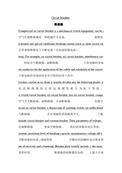
Circuit breaker断路器Compressed air circuit breaker is a mechanical switch equipment, can be i 空气压缩断路器是一种机械开关设备,能够在n normal and special conditions breaking current (such as short circuit cur 正常和特殊情况下开断电流(比如说短路电流)。
rent). For example, air circuit breaker, oil circuit breaker, interference circ 例如空气断路器、油断路器,干扰电路的导体uit conductor for the application of the safety and reliability of the circuit 干扰电路的导体因该安全可靠的应用于其中,breaker, current in arc from is usually divided into the following grades: a 电流断路器按灭弧远离通常被分为如下等级:ir switch circuit breaker, oil circuit breaker, less oil circuit breaker, compr 空气开关断路器、油断路器、少油断路器、压缩空essed air circuit breaker, a degaussing of isolating switch, six sulfur hexaf 气断路器、具有消磁性质的隔离开关、六氟luoride circuit breaker and vacuum breaker. Their parameters of voltage, 化硫断路器和真空断路器。
他们的参数有电压等级、current, insulation level of breaking capacity, instantaneous voltage off ti 开断容量的电流、绝缘等级开断时间的瞬时电压恢复和me of recovery and a bombing. Breaker plate usually include: 1 the maxi 轰炸时间。
电力系统继电保护论文中英文资料Relay protection development present situation[Abstract ]reviewed our country electrical power system relay protection technological devil orpiment process,has outlined the microcomputer relay protection technology achievement, pro posed the future relay protection technological development tendency will be: Computerizes, n networked,protects, the control,the survey,the data communication integration and the artificial I intellectualization.[Key word ]relay protection present situation development,relay protections future development1 relay protection development present situationThe electrical power system rapid development to the relay protection proposed unceasingly t he new request,the electronic technology,computer technology and the communication rapid development unceasingly has poured into the new vigor for the relay protection technology de velopment,therefore,the relay protection technology is advantageous, has completed the deve lopment 4 historical stage in more than 40 years time。

Electric Power SystemElectrical power system refers to remove power and electric parts of the part,It includes substation, power station and distribution. The role of the power grid is connected power plants and users and with the minimum transmission and distribution network disturbance through transport power, with the highest efficiency and possibility will voltage and frequency of the power transmission to the user fixed .Grid can be divided into several levels based on the operating voltage transmission system, substructure, transmission system and distribution system, the highest level of voltage transmission system is ZhuWangJia or considered the high power grids. From the two aspects of function and operation, power can be roughly divided into two parts, the transmission system and substation. The farthest from the maximum output power and the power of the highest voltage grade usually through line to load. Secondary transmission usually refers to the transmission and distribution system is that part of the middle. If a plant is located in or near the load, it might have no power. It will be direct access to secondary transmission and distribution system. Secondary transmission system voltage grade transmission and distribution system between voltage level. Some systems only single second transmission voltage, but usually more than one. Distribution system is part of the power system and its retail service to users, commercial users and residents of some small industrial users. It is to maintain and in the correct voltage power to users responsible. In most of the system, Distribution system accounts for 35% of the total investment system President to 45%, and total loss of system of the half .More than 220kv voltage are usually referred to as Ultra high pressure, over 800kv called high pressure, ultra high voltage and high pressure have important advantages, For example, each route high capacity, reduce the power needed for the number of transmission. In as high voltage to transmission in order to save a conductor material seem desirable, however, must be aware that high voltage transmission can lead to transformer, switch equipment and other instruments of spending increases, so, for the voltage transmission to have certain restriction, allows it to specific circumstances in economic use. Although at present, power transmission most is through the exchange of HVDC transmission, and the growing interest in, mercury arc rectifier and brake flow pipe into the ac power generation and distribution that change for the high voltage dc transmission possible.Compared with the high-voltage dc high-voltage ac transmission has the following some advantages: (1) the communication with high energy; (2) substation of simple maintenance and communication cost is low; (3) ac voltage can easily and effectively raise or lower, it makes the power transmission and high pressure With safety voltage distributionHVDC transmission and high-voltage ac transmission has the following advantages: (1) it only need two phase conductors and ac transmission to three-phase conductors; (2) in the dc transmission impedance, no RongKang, phase shift and impact overvoltage; (3) due to the same load impedance, no dc voltage, and transfer of the transmission line voltage drop less communication lines, and for this reason dc transmission line voltage regulator has better properties; (4) in dc system without skin effect. Therefore, the entire section of route conductors are using; (5) for the same work, dc voltage potential stress than insulation. Therefore dc Wire need less insulation; (6) dc transmission line loss, corona to little interference lines of communication; (7) HVDC transmission without loss of dielectric, especially in cable transmission; (8) in dc system without stability and synchronization of trouble.A transmission and the second transmission lines terminated in substation or distribution substations, the substation and distribution substations, the equipment including power and instrument transformer and lightning arrester, with circuit breaker, isolating switch, capacitor set, bus and a substation control equipment, with relays for the control room of the equipment. Some of the equipment may include more transformer substations and some less, depending on their role in the operation. Some of the substation is manual and other is automatic. Power distribution system through the distribution substations. Some of them by many large capacity transformer feeders, large area to other minor power transformer capacity, only a near load control, sometimes only a doubly-fed wire feeders (single single variable substation)Now for economic concerns, three-phase three-wire type communication network is widely used, however, the power distribution, four lines using three-phase ac networks.Coal-fired power means of main power generating drive generators, if coal energy is used to produce is pushing the impeller, then generate steam force is called the fire. Use coal produces steam to promote the rotating impeller machine plant called coal-fired power plants. In the combustion process, the energy stored in the coal to heat released,then the energy can be transformed into the form within vapor. Steam into the impeller machine work transformed into electrical energy.Coal-fired power plants could fuel coal, oil and natural gas is. In coal-fired power plant, coal and coal into small pieces first through the break fast, and then put out. The coal conveyer from coal unloader point to crush, then break from coal, coal room to pile and thence to power. In most installations, according to the needs of coal is, Smash the coal storage place, no coal is through the adjustable coal to supply coal, the broken pieces of coal is according to the load changes to control needs. Through the broken into the chamber, the coal dust was in the second wind need enough air to ensure coal burning.In function, impeller machine is used to high temperature and high pressure steam energy into kinetic energy through the rotation, spin and convert electricity generator. Steam through and through a series of impeller machine parts, each of which consists of a set of stable blade, called the pipe mouth parts, even in the rotor blades of mobile Li called. In the mouth parts (channel by tube nozzle, the steam is accelerating formation) to high speed, and the fight in Li kinetic energy is transformed into the shaft. In fact, most of the steam generator is used for air is, there is spread into depression, steam turbine of low-pressure steam from the coagulation turbine, steam into the condenses into water, and finally the condensate water is to implement and circulation.In order to continuous cycle, these must be uninterrupted supply: (1) fuel; (2) the air (oxygen) to the fuel gas burning in the configuration is a must; (3) and condenser, condensed from the condensed water supply, sea and river to lake. Common cooling tower; (4) since water vapour in some places in circulation, will damage process of plenty Clean the supply.The steam power plant auxiliary system is running. For a thermal power plant, the main auxiliary system including water system, burning gas and exhaust systems, condensation system and fuel system. The main auxiliary system running in the water pump, condensation and booster pump, coal-fired power plants in the mill equipment. Other power plant auxiliary equipment including air compressors, water and cooling water system, lighting and heating systems, coal processing system. Auxiliary equipment operation is driven by motor, use some big output by mechanical drive pump and some of the impeller blades, machine drive out from the main use of water vaporimpeller machine. In coal-fired power plant auxiliary equipment, water supply pump and induced draft fan is the biggest need horsepower.Most of the auxiliary power generating unit volume increased significantly in recent years, the reason is required to reduce environment pollution equipment. Air quality control equipment, such as electrostatic precipitator, dust collection of flue gas desulfurization, often used in dust in the new coal-fired power plants, and in many already built in power plant, the natural drive or mechanical drive, fountain, cooling tower in a lake or cooling canal has been applied in coal-fired power plants and plants, where the heat release need to assist cooling system.In coal-fired power stations, some device is used to increase the thermal energy, they are (1) economizer and air preheater, they can reduce the heat loss; (2) water heater, he can increase the temperature of water into boiling water heaters; (3) they can increase and filter the thermal impeller.Coal-fired power plants usually requires a lot of coal and coal reservoirs, however the fuel system in power plant fuel handling equipment is very simple, and almost no fuel oil plants.The gas turbine power plants use gas turbine, where work is burning gas fluid. Although the gas turbine must burn more expensive oil or gas, but their low cost and time is short, and can quickly start, they are very applicable load power plant. The gas turbine burn gas can achieve 538 degrees Celsius in the condensing turbine, however, the temperature is lower, if gas turbine and condenser machine, can produce high thermal efficiency. In gas turbine turbine a combined cycle power plant. The gas through a gas turbine, steam generator heat recovery in there were used to generate vapor heat consumption. Water vapor and then through a heated turbine. Usually a steam turbine, and one to four gas turbine power plant, it must be rated output power.。
某钢铁企业变电所保护系统及防护系统设计1 绪论1.1 变电站继电保护的发展变电站是电力系统的重要组成部分,它直接影响整个电力系统的安全与经济运行,失恋系发电厂和用户的中间环节,起着变换和分配电能的作用,电气主接线是发电厂变电所的主要环节,电气主接线的拟定直接关系着全厂电气设备的选择、配电装置的布置、继电保护和自动装置的确定,是变电站电气部分投资大小的决定性因素。
继电保护的发展现状,电力系统的飞速发展对继电保护不断提出新的要求,电子技术、计算机技术与通信技术的飞速发展又为继电保护技术的发展不断地注入了新的活力,因此,继电保护技术得天独厚,在40余年的时间里完成了发展的4个历史阶段。
随着电力系统的高速发展和计算机技术、通信技术的进步,继电保护技术面临着进一步发展的趋势。
国内外继电保护技术发展的趋势为:计算机化,网络化,保护、控制、测量、数据通信一体化和人工智能化。
继电保护的未来发展,继电保护技术未来趋势是向计算机化,网络化,智能化,保护、控制、测量、数据通信一体化发展。
微机保护技术的发展趋势:①高速数据处理芯片的应用②微机保护的网络化③保护、控制、测量、信号、数据通信一体化④继电保护的智能化1.2本文的主要工作在本次毕业设计中,我主要做了关于某钢铁企业变电所保护系统及防护系统设计,充分利用自己所学的知识,严格按照任务书的要求,围绕所要设计的主接线图的可靠性,灵活性进行研究,包括:负荷计算、主接线的选择、短路电流计算,主变压器继电保护的配置以及线路继电保护的计算与校验的研究等等。
1.3 设计概述1.3.1 设计依据1)继电保护设计任务书。
2)国标GB50062-92《电力装置的继电保护和自动装置设计规范》3)《工业企业供电》1.3.2 设计原始资料本企业共有12个车间,承担各附属厂的设备、变压器修理和制造任务。
1、各车间用电设备情况用电设备明细见表1.1所示。
2、负荷性质本厂大部分车间为一班制,少数车间为两班或者三班制,年最大有功负荷利用小时数为h2300。
Page 1.The Production of Electrical Energy(电能生产)1 English textFrom reference 1Should the generation be not adequate to balance the load demand, it is imperative that one of following alternatives be considered for keeping the system in operating condition:1. Staring fast peaking units,2. Load shedding for unimportant loads,3. generation rescheduling.It is apparent from the above that since the voltage specifications are not stringent, load frequency control is by far the most important in power system control.In order to understand the frequency control, consider a small step-increase in load. The initial distribution of the load increment is determined by the system simpedance; and the sistantaneous relative generator rotor positions. The energy required to supply the load increment is drawn from the kinetic energy of rotating machines. As a result, the system frequency drops. The distribution of load during this period among the various machines is determined by the inertias of the rotors of the generators partaking in process. This problem is stability analysis of the system.After the speed or frequency fall due to reduction in stored energy in the rotors has taken place, the drop is sensed by the governors and they divide the load increment between the machines as determined by the droops of the respective governor characterstics. Subsequently, secondary control restores the system frequency to its normal value by readjusting the governor characteristics. Keywords:load frequency controlFrom reference 2Modern power systems are so large that it is impossible to design a single central control system that would handle the overall control job. It is extremely useful take into account the weak links in the system and then apply control throughdecomposition. The demarcation of load frequency control and Mavar voltage control characteristics is one such decomposition. Geographical and functional decomposition are successfully applied to power systems and this leads to the concept of area control.A modern power system can be divided into several areas for load frequency control. Each control area fulfils the following:1.The area is a geographically contious portion of a large interconnected area, which adjusts its own generation to accommodate load changes within its precincts.2.Under normal conditions of operation, it changes bulk power with neighboring areas.3.Under abnormal conditions of operation, it may deviate from predetermined schedules and provide assistance to any neighboring control area in the system.4.It is expected, in addition, to partake with the other areas in the system in a suitable manner in the system frequency regulation.The rotors of all generators in a control area swing together for load change. Thus, a coherent group of generators within a geographical region may constitute a control area which is connected to other similar areas by weak tie lines.Keywords:areas load frequency controlFrom reference 3For plant loading schedules in thermal systems, load prediction up to two hours in advance is necessary while for unit commitment schedules prediction up to 24 hours is sufficient. Also, at all sations and control centers, short-time prediction is needed for storage and display of advance information. Based on this information, predictive security assessment of the system is made. This also helps to contain the rates of change of generator outputs within their permissible limits.For the implementation of economic scheduling of generation using digital computers, detailed estimates of the future load demands are essential in order to allow sufficient time for the calculation and implementation of the generator schedules. Whatever method is envisaged for the calculation of such economic schedules consistent with the security and spare requirements of the system, the schedules should be calculatedevery 15 or 30 minutes and each economic schedule should be a predictive one ,for at least about 30 minutes ahead of event. It is then obvious that the predictions are to be revised frequently in the light of any fresh information so as to minimize the estimation errors.Peak load demand forecasts are useful in determining the investment required for additional generating and transmission capacities required. Forecasts for planning require data extending over several previous years. Meaningful forecasts can be obtained with lead time of 3 to 5 years.Keywords:load predictionFrom reference 4In this method, the load is separated into two main components. The first component is a base load which is of fixed value and the second a variable component which is a function of the weather conditions.Estimates can be made 24 hours ahead, using the weather forecast. The temperature base for weighting the effect of the predicated temperature on the load is the normal, mean temperature of the month. The normal, mean temperature of the month has zero weight. Similarly the change in consumers demand due to cloudy weather may be assumed to vary in direct proportion to the degree of cloudiness. This in turn may be expressed by an illumination index with fair, clear sky corresponding to zero weight.The base load is determined from past records. Proper weighting of the elements of the weather will be attained only after several trials. The method of prediction stabilizes after this trial period. It may be noted that the base loads for week days and weekend will generally be different for any hour.Using these base loads, a load estimate based on the best available weather forecast can be made using proper weighting of meteorological factors like temperature, cloudiness, wind velocity, etc.Keywords:proper weighting of the elements of the weather2 中文翻译及分析出自文献1:万一发电量不足以平衡负荷需求,要使电力系统处于运行状态,必须考虑采取以下选择方法中的一种:1、启动快速峰荷机组2、对不重要的用户实行拉闸断电3、重新制定发电计划从上述情况来看,电压技术的要求并不严格,目前为止负荷频率控制是电力系统控制中最重要的手段。
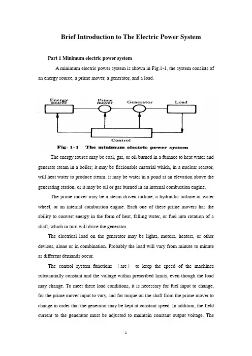
Brief Introduction to The Electric Power SystemPart 1 Minimum electric power systemA minimum electric power system is shown in Fig.1-1, the system consists of an energy source, a prime mover, a generator, and a load.The energy source may be coal, gas, or oil burned in a furnace to heat water and generate steam in a boiler; it may be fissionable material which, in a nuclear reactor, will heat water to produce steam; it may be water in a pond at an elevation above the generating station; or it may be oil or gas burned in an internal combustion engine.The prime mover may be a steam-driven turbine, a hydraulic turbine or water wheel, or an internal combustion engine. Each one of these prime movers has the ability to convert energy in the form of heat, falling water, or fuel into rotation of a shaft, which in turn will drive the generator.The electrical load on the generator may be lights, motors, heaters, or other devices, alone or in combination. Probably the load will vary from minute to minute as different demands occur.The control system functions (are)to keep the speed of the machines substantially constant and the voltage within prescribed limits, even though the load may change. To meet these load conditions, it is necessary for fuel input to change, for the prime mover input to vary, and for torque on the shaft from the prime mover to change in order that the generator may be kept at constant speed. In addition, the field current to the generator must be adjusted to maintain constant output voltage. Thecontrol system may include a man stationed in the power plant who watches a set of meters on the generator output terminals and makes the necessary adjustments manually. In a modern station, the control system is a servomechanism that senses generator-output conditions and automatically makes the necessary changes in energy input and field current to hold the electrical output within certain specifications..Part 2 More Complicated SystemsIn most situations the load is not directly connected to the generator terminals. More commonly the load is some distance from the generator, requiring a power line connecting them. It is desirable to keep the electric power supply at the load within specifications. However, the controls are near the generator, which may be in another building, perhaps several miles away.If the distance from the generator to the load is considerable, it may be desirable to install transformers at the generator and at the load end, and to transmit the power over a high-voltage line (Fig.1-2). For the same power, the higher-voltage line carries less current, has lower losses for the same wire size, and provides more stable voltage.In some cases an overhead line may be unacceptable. Instead it may be advantageous to use an underground cable. With the power systems talked above, the power supply to the load must be interrupted if, for any reason, any component of the system must be moved from service for maintenance or repair. Additional system load may require more power than the generator can supply. Another generator with its associated transformers and high-voltage line might be added.It can be shown that there are some advantages in making ties between the generators (1) and at the end of the high-voltage lines (2 and 3), as shown in Fig.1-3. This system will operate satisfactorily as long as no trouble develops or no equipmentneeds to be taken out of service.The above system may be vastly improved by the introduction of circuit breakers, which may be opened and closed as needed. Circuit breakers added to the system, Fig.1-4, permit selected piece of equipment to switch out of service without disturbing the remainder of system. With this arrangement any element of the system may be deenergized for maintenance or repair by operation of circuit breakers.Of course, if any piece of equipment is taken out of service, then the total load must be carried by the remaining equipment. Attention must be given to avoid overloads during such circumstances. If possible, outages of equipment are scheduled at times when load requirements are below normal.Fig.1-5 shows a system in which three generators and three loads are tied together by three transmission lines. No circuit breakers are shown in this diagram, although many would be required in such a system.Part 3 Typical System LayoutThe generators, lines, and other equipment which form an electric system are arranged depending on the manner in which load grows in the area and may be rearranged from time to time.However, there are certain plans into which a particular system design may be classified. Three types are illustrated: the radial system, the loop system, and the network system. All of these are shown without the necessary circuit breakers. In each of these systems, a single generator serves four loads.The radial system is shown in Fig.1-6. Here the lines form a “tree” spreading out from the generator. Opening any line results in interruption of power to one or more of the loads.The loop system is illustrated in Fig.1-7. With this arrangement all loads may be served even though one line section is removed from service. In some instances during normal operation, the loop may be open at some point, such as A. In case a line section is to be taken out, the loop is first closed at A and then the line section removed. In this manner no service interruptions occur.Fig.1-8 shows the same loads being served by a network. With this arrangement each load has two or more circuits over which it is fed.Distribution circuits are commonly designed so that they may be classified as radial or loop circuits. The high-voltage transmission lines of most power systems are arranged as network. The interconnection of major power system results in networks made up by many line sections.Part 4 Auxiliary EquipmentCircuit breakers are necessary to deenergize equipment either for normal operation or on the occurrence of short circuits. Circuit breakers must be designed to carry normal-load currents continuously, to withstand the extremely high currents that occur during faults, and to separate contacts and clear a circuit in the presence of fault. Circuit breakers are rated in terms of these duties.When a circuit breaker opens to deenergize a piece of equipment, one side of the circuit breaker usually remains energized, as it is connected to operating equipment. Since it is sometimes necessary to work on the circuit breaker itself, it is also necessary to have means by which the circuit breaker may be completely disconnected from other energized equipment. For this purpose disconnect switches are placed in series with the circuit breakers. By opening these disconnectors, thecircuit breaker may be completely deenergized, permitting work to be carried on in safety.Various instruments are necessary to monitor the operation of the electric power system. Usually each generator, each transformer bank, and each line has its own set of instruments, frequently consisting of voltmeters, ammeters, wattmeters, and varmeters.When a fault occurs on a system, conditions on the system undergo a sudden change. V oltages usually drop and currents increase. These changes are most noticeable in the immediate vicinity of fault. On-line analog computers, commonly called relays, monitor these changes of conditions, make a determination of which breaker should be opened to clear the fault, and energize the trip circuits of those appropriate breakers. With modern equipment, the relay action and breaker opening causes removal of fault within three or four cycles after its initiation.The instruments that show circuit conditions and the relays that protect the circuits are not mounted directly on the power lines but are placed on switchboards in a control house. Instrument transformers are installed on the high-voltage equipment, by means of which it is possible to pass on to the meters and relays representative samples of the conditions on the operating equipment. The primary of a potential transformer is connected directly to the high-voltage equipment. The secondary provides for the instruments and relays a voltage which is a constant fraction of voltage on the operating equipment and is in phase with it;similarly, a current transformer is connected with its primary in the high-current circuit. The secondary winding provides a current that is a known fraction of the power-equipment current and is in phase with it.Bushing potential devices and capacitor potential devices serve the same purpose as potential transformers but usually with less accuracy in regard to ratio and phase angle.中文翻译:电力系统的简介第一部分:最小电力系统一个最小电力系统如图1-1所示,系统包含动力源,原动机,发电机和负载。
外文资料翻译Power System AutomationPower system integration is the act of communication data to, or among IED s in the I&C system and remote users. Substation integration refers to combining data from the IED′s local to a substation so that there is a s ingle point of contact in the substation for all of the I&C data. Poletop devices often communicate to the substation via wireless or fiber connections. Remote and local substation and feeder control is passed through the substation controller acting as a single point of contact. Some systems bypass the substation controller by using direct connections to the poletop devices, such as RTU s, protective relays, and controllers.Power system automation is the act of automatically controlling the power system via I&C devices. Substation automation refers to using IED data, control and automation capabilities within the substation, and control commands from remote users to control power system devices. Since true substation automation relies on substation integration, the terms are often used interchangeably.Power system automation includes processes associated with generation and delivery of power. A subset of the process deal with delivery of power at transmission and distribution levels, which is power delivery automation. Together, monitoring and control of power delivery system in the substation and on the poletop reduce the occurrence of outages and shorten the duration of outages that do occur. The IED′s, communications protocols, and communications methods described in previous sections, work together as a system to perform power system automation.Though each utility is unique, most consider power delivery automation of transmission and distribution substation and feeders to include :Supervisory Control and Data Acquisition(SCADA)-operatorsupervision and control;Distribution Automation-fault location, auto-isolation, auto-sectionalizing, and auto-restoration;Substation Automation-breaker failure, reclosing, battery monitoring, dead substation transfer, and substation load transfer;Energy Management System (EMS)-load flow, VAR and voltage monitoring and control, generation control, transformer and feeder load balancing;Fault analysis and device maintenance.System without automated control still have the advantages of remote monitoring and operator control of power system devices, which includes: Remote monitoring and control of circuit breakers and automated switches;Remote monitoring of non-automated switches and fuses;Remote monitoring and control of capacitor banks;Remote monitoring and voltage control;Remote power quality monitoring and control.IED s described in the overview are used to perform power system integration and automation. Most designs require that the one IED act as the substation controller and perform data acquisition and control of the other IED s. The substation controllers is often called upon to support system automation tasks as well. The communications industry uses the term client/server for a device that acts as a master, or client, retrieving data from some devices and then acts as a slaver, a server, sending this data to other devices. The client/server collecting and concentrating dynamically. A data concentrator creates a substation databases by collecting and concentrating dynamic data from several devices. In this fashion, essential subsets of data from each IED are forwarded to a master through one data transfer. The concentrator databases is used to pass data between IED s that are not directly connected.A substation archive client/server collects and archives data from several devices. The archive data is retrieved when it is convenient for the userto do so.The age of the IED s now in substations varies widely. Many of these IED s are still useful but lack the most recent protocols. A communications processor that can communicate with each IED via a unique baud rate and protocol extends the time that each IED is useful. Using a communications processor for substation integration also easily accommodates future IED s. It is rare for all existing IED s to be discarded during a substation integration upgrade project.The benefits of monitoring, remote control, and automation of power delivery include improved employee and public safety, and deferment of the cost of purchasing new equipment. Also, reduced operation and maintenance costs are realized through improved use of existing facilities and optimized performance of the power system through reduced losses associated with outages and improved voltage profile. Collection of information can result in better planning and system design, and increased customer satisfaction will result from improved responsiveness, service reliability, and power quality.Power system automation includes a variety of equipment. The principal items are listed and briefly described below.Instrument transformers are used to sense power system current and voltage. They are physically connected to power system apparatus and convert the actual power system signals, which includes high voltage and current magnitudes, down to lower signal levels.Transducers convert the analog output of an instrument transformer from one magnitude to another or from one value type to another, such as from an ac current to dc voltage.As the name implies, a remote terminal device, RTU, is an IED that can be installed in a remote location, and acts as a termination point for filed contacts. A dedicated pair of copper conductors are used to sense every contract and transducer value. These conductors originated at the power system device, are installed in trenches or overhead cable trays, and are then terminated on panels within the RTU. The RTU can transfer collected data to other devices andreceive data and control commands from other device through a serial port. User programmable RTUs are referred to as “smart RTUs.”A communication switch is a device that switches between several serial ports when it is told to do so. The remote user initiates communications with the port switch via a connection to the substation , typically a leased line or dial-up telephone connection. Once connected, the user can route their communication through the port switch to one of the connected substation IEDs. The port switch merely “passes through” the IED communication.A meter is an IED that is used to create accurate measurement of power system current, voltage, and power values. Metering values such as demand and peak are saved within the meter to create historical information about the activity of the power system.A digital fault recorder ,is an IED that records information about power system disturbances. It is capable of storing data in digital format when triggered by conditions detected on the power system. Harmonics, frequency, and voltage are examples of data captured by DFRs.Load tap changer are devices used to change the tap position on transformers. These devices work automatically or can be controlled via another local IED or form a remote operator or process.Recloser controllers remotely control the operation of automated reclosers and switches. These devices monitor and store power system conditions and determine when to perform control actions. They also accept commands form a remote operator or process.电力系统自动化电力系统集成是在I&C系统中的IED和远程用户之间进行数据通信的操作。
电气工程高层建筑论文中英文资料外文翻
译文献
本文的主要目标是翻译一些电气工程和高层建筑方面的外文文献。
这些文献分别为:
1. "Application of lateral tuned mass damper to high-rise structure under random wind excitations",这篇文章主要介绍了侧向调谐质量阻尼器(lateral tuned mass damper)在高层建筑中的应用。
该文通过计算分析和试验研究,得出了调谐阻尼器的结构参数和其对建筑物抗震能力的影响。
2. "Reliability Analysis of Power Supply System in High-rise Building",这篇文章主要介绍了高层建筑电力供应系统的可靠性分析。
该文分别从电力系统的结构、功能和基本原理入手,阐述了电力系统的可靠性分析方法,并根据有关标准和规范,对高层建筑电力系统的可靠性进行了分析。
3. "Dynamic Analysis on Earthquake Resistance of High-rise Buildings Based on Pushover Method",该文介绍了基于 Pushover 方
法对高层建筑的抗震性能进行动力学分析。
该方法通过对结构的位移、剪力和弯矩等特性进行预测,可以更加准确地评估高层建筑的抗震性能。
以上三篇文献分别介绍了高层建筑中的电气工程和抗震技术方面的研究成果,对于高层建筑的设计和建造具有一定的参考价值。
电力系统电力系统介绍随着电力工业的增长,与用于生成和处理当今大规模电能消费的电力生产、传输、分配系统相关的经济、工程问题也随之增多。
这些系统构成了一个完整的电力系统。
应该着重提到的是生成电能的工业,它与众不同之处在于其产品应按顾客要求即需即用。
生成电的能源以煤、石油,或水库和湖泊中水的形式储存起来,以备将来所有需。
但这并不会降低用户对发电机容量的需求。
显然,对电力系统而言服务的连续性至关重要。
没有哪种服务能完全避免可能出现的失误,而系统的成本明显依赖于其稳定性。
因此,必须在稳定性与成本之间找到平衡点,而最终的选择应是负载大小、特点、可能出现中断的原因、用户要求等的综合体现。
然而,网络可靠性的增加是通过应用一定数量的生成单元和在发电站港湾各分区间以及在国内、国际电网传输线路中使用自动断路器得以实现的。
事实上大型系统包括众多的发电站和由高容量传输线路连接的负载。
这样,在不中断总体服务的前提下可以停止单个发电单元或一套输电线路的运作。
当今生成和传输电力最普遍的系统是三相系统。
相对于其他交流系统而言,它具有简便、节能的优点。
尤其是在特定导体间电压、传输功率、传输距离和线耗的情况下,三相系统所需铜或铝仅为单相系统的75%。
三相系统另一个重要优点是三相电机比单相电机效率更高。
大规模电力生产的能源有:1.从常规燃料(煤、石油或天然气)、城市废料燃烧或核燃料应用中得到的蒸汽;2.水;3.石油中的柴油动力。
其他可能的能源有太阳能、风能、潮汐能等,但没有一种超越了试点发电站阶段。
在大型蒸汽发电站中,蒸汽中的热能通过涡轮轮转换为功。
涡轮必须包括安装在轴承上并封闭于汽缸中的轴或转子。
转子由汽缸四周喷嘴喷射出的蒸汽流带动而平衡地转动。
蒸汽流撞击轴上的叶片。
中央电站采用冷凝涡轮,即蒸汽在离开涡轮后会通过一冷凝器。
冷凝器通过其导管中大量冷水的循环来达到冷凝的效果,从而提高蒸汽的膨胀率、后继效率及涡轮的输出功率。
而涡轮则直接与大型发电机相连。
变电站中英文资料对照外文翻译文献综述XXXns are an essential part of electrical power systems。
servingas the interface een high-voltage n lines and lower-voltage n lines。
They play a critical role in XXX homes。
businesses。
and industries.Types of nsThere are several types of ns。
including n ns。
n ns。
and customer XXX to the end-users and step down the voltage for n to XXX a single customer or group of customers.XXXns consist of us components。
including transformers。
circuit breakers。
switches。
XXX are used to step up or step down thevoltage of the electricity。
XXX are used to control the flow ofXXX to the system.XXXXXX stages。
including site n。
layout design。
equipment n。
XXX n lines。
land availability。
and environmental ns。
The layout design involves determining the placement of equipment。
XXX appropriate transformers。
circuit breakers。
and other components。
毕业设计英文文献翻译(电力方向附带中文)大学毕业设计英文文献翻译,关于电力系统方向,电力谐波!绝对原创!HarmonicsService reliability and quality of power have become growing concerns for many facility managers, especially with the increasing sensitivity of electronic equipment and automated controls. There are several types of voltage fluctuations that can cause problems, including surges and spikes, sags, harmonic distortion, and momentary disruptions. Harmonics can cause sensitive equipment to malfunction and other problems, including overheating of transformers and wiring, nuisance breaker trips, and reduced power factor.What Are Harmonics?Harmonics are voltage and current frequencies riding on top of the normal sinusoidal voltage and current waveforms. Usually these harmonic frequencies are in multiples of the fundamental frequency, which is 60 hertz (Hz) in the US and Canada. The mostcommon source of harmonic distortion is electronic equipment using switch-mode power supplies, such as computers, adjustable-speed drives, and high-efficiency electronic light ballasts.Harmonics are created by these Dswitching loads‖ (also called “nonlinear loads,‖ because current does not vary smoothly with voltage as it does with simple resistive and reactive loads): Each time the current is switched on and off, a current pulse is created. The resulting pulsed waveform is made up of a spectrum of harmonic frequencies, including the 60 Hz fundamental and multiples of it. This voltage distortion typically results from distortion in the current reacting with system impedance. (Impedance is a measure of the total opposi tion―resistance, capacitance, and inductance―to the flow of an alternating current.) The higher-frequency waveforms, collectively referred to as total harmonic distortion (THD), perform no useful work and can be asignificant nuisance.Harmonic waveforms are characterized by their amplitude and harmonic number. In the U.S. and Canada, the third harmonic is 180 Hz―or 3 x 60 Hz―and the fifth harmonic is 300 Hz (5 x 60Hz). The third harmonic (and multiples of it) is the largest problem in circuits with single-phase loads such as computers and fax machines. Figure 1 shows how the 60-Hz alternating current (AC) voltage waveform changes when harmonics are added.大学毕业设计英文文献翻译,关于电力系统方向,电力谐波!绝对原创!The Problem with HarmonicsAny distribution circuit serving modern electronic devices will contain some degree of harmonic frequencies. The harmonics do not always cause problems, but the greater the power drawn by these modern devices or other nonlinear loads, the greater the level of voltage distortion. Potential problems (or symptoms of problems) attributed to harmonics include:■ Malfunction of sensitive equipment■ Random tripping of circuit breakers■ Flickering lights■ Very high neutral currents■ Overheated phase conductors, panels, and transformers ■ Premature failure of transformers and uninterruptible power supplies (UPSs)■ Reduced power factor■ Reduced system capacity (because harmonics create additional heat, transformers and otherdistribution equipment cannot carry full rated load)Identifying the ProblemWithout obvious symptoms such as nuisance breaker trips or overheated transformers, how do you determine whether harmonic current or voltages are a cause for concern? Here are several suggestions for simple, inexpensive measurements that a facility manager or staff electrician could take, starting at the outlet and moving upstream:■ Measure the peak and root mean square (RMS) voltage at a sample of receptacles. The Dcrest factor‖ is the ra tio of peak to RMS voltage. For a perfectly sinusoidal voltage, the crest factor will be 1.4. Low crest factor is a clear indicator of the presence of harmonics. Note that these measurements must be performed with a Dtrue RMS‖ meter―one that doesn‘t assume a perfectly sinusoidal waveform.■ Inspect distribution panels. Remove panel covers and visually inspect components for signs of overheating, including discolored or receded insulation or discoloration of terminal screws. If you see any of these symptoms, check that connectionsare tight (since loose connections could also cause overheating), and compare currents in all conductors to their ratings.■ Measure phase and neutral currents at the transformer secondary with clamp-on current probes. If no harmonics are being generated, the neutral current of a three-phase distribution system carries only the imbalance of the phase currents. In a well-balanced three-phase distribution system, phase currents will be very similar, and current in the neutral conductor should be much lower than phase current and far below its rated current capacity. If phase currents are similar and neutral current exceeds their imbalance by a wide margin, harmonics are present. If neutral current is above 70 percent of the cond uctor‘s rated capacity, you need to mitigate the problem.■Compare transformer temperature and loading with nameplate temperature rise and capacity ratings. Even lightly loaded transformers can overheat if harmonic current is high. A transformer that is near or over its rated temperature rise but is loaded well below its rated capacity is a clear sign that harmonics are at work. (Many transformers have built-in temperature gauges. If yours does not, infrared thermography can be used to detect overheating.)大学毕业设计英文文献翻译,关于电力系统方向,电力谐波!绝对原创!In addition to these simple measurements, many power-monitoring devices are now commercially available from a variety of manufacturers to measure and record harmonic levels. These instruments provide detailed information on THD, as well as on the intensity of individual harmonic frequencies. After taking the appropriate measurements to determine whether you have high levels of harmonics and, if so, to find the source, you will be well-positioned to choose the best solution.Solutions to Harmonics ProblemsThe best way to deal with harmonics problems is through prevention: choosing equipment and installation practices that minimize the level of harmonics in any one circuit or portion of a facility. Many power quality problems, including those resulting from harmonics, occur when new equipment is haphazardly added to older systems. However, even within existing facilities, the problems can often be solved with simple solutions such as fixing poor or nonexistent grounding on individual equipment or the facility as a whole, moving a few loads between branch circuits, or adding additional circuits to help isolate the sensitiveequipment from what is causing the harmonic distortion. If the problems cannot be solved by these simple measures, there are two basic choices: to reinforce the distribution system to withstand the harmonics or to install devices to attenuate or remove the harmonics. Reinforcing the distribution system means installing double-size neutral wires or installing separate neutral wires for each phase, and/or installing oversized or Krated transformers, which allow for more heat dissipation. There are also harmonic-rated circuit breakers and panels, which are designed to prevent overheating due to harmonics. This option is generally more suited to new facilities, because the costs of retrofitting an existing facility in this way could be significant. Strategies for attenuating harmonics, from cheap to more expensive, include passive harmonic filters, isolation transformers, harmonic mitigating transformers (HMTs), the Harmonic Suppression System (HSS) from Harmonics Ltd., and active filters(Table 1).Passive filters (also called traps) include devices that provide low-impedance paths to divert harmonics to ground and devices that create a higher-impedance path to discourage the flow of harmonics. Both of these devices, by necessity, change theimpedance characteristics of the circuits into which they are inserted. Another weakness of passive harmonic technologies is that, as their name implies, they cannot adapt to changes in the electrical systems in which they operate. This means that changes to the electrical system (for example, the addition or removal of power factorCcorrection capacitors or the addition of more nonlinear loads) could cause them to be overloaded or to create Dresonances‖ that could actually amplify, rather than diminish, harmonics.Active harmonic filters, in contrast, continuously adjust their behavior in response to the harmonic current content of the monitored circuit, and they will not cause resonance. Like an automatic transmission in a car, active filters are designed to accommodate a full range of expected operating conditions upon installation, without requiring further adjustments by the operator.Isolation transformers are filtering devices that segregate harmonics in the circuit in which they are created, protecting upstream equipment from the effects of harmonics. These transformers do not remove the problem in the circuit generating the harmonics, but they can prevent the harmonics from affecting more sensitive equipment elsewhere within the facility.大学毕业设计英文文献翻译,关于电力系统方向,电力谐波!绝对原创!Harmonic mitigating transformers actually do relieve problematic harmonics. HMTs can be quite cost-effective in the right application, because they can both improve reliability and reduce energy costs. The right application includes transformers that are heavily or moderately loaded and where high levels of harmonic currents are present. In addition, HMTs are very effective in supporting critical loads that are backed up by a UPS. UPSs and backup generators tend to have high impedance, which results in high voltage distortion under nonlinear loading. Because of this, equipment that operates flawlessly when supplied by utility power may malfunction when the backup system engages during a utility outage. Note that some of these power systems have output filters (either passive or active) to control harmonic levels. The presence or absence of such filters should be determined before adding an HMT.The Harmonics Ltd. Harmonic Suppression System is a unique solution for single-phase loads that is designed to suppress the third harmonic. An HSS is generally more expensive than an HMT, but it is designed to attenuate the harmonicsproblems throughout the entire distribution system, not just upstream of the transformer. The types of facilities that present the best opportunities for HSS installation are those that place a very high premium on power quality and reliability, such as server farms, radio and television broadcast studios, and hospitals. (See .) Economic EvaluationEvaluating the life-cycle costs and effectiveness of harmonics mitigation technologies can be ve ry challenging―beyond the expertise of most industrial facility managers. After performing the proper measurement and analysis of the harmonics problem, this type of evaluation requires an analysis of the costs of the harmonics problem (downtime of sensitive equipment, reduced power factor, energy losses or potential energy savings) and the costs of the solutions. A good place to start in performing this type of analysis is to ask your local utility or electricity provider for assistance. Many utilities offer their own power quality mitigation services or can refer you to outside power quality service providers.Additional ResourcesInstitute of Electrical and Electronics Engineers (IEEE),Standard 519-1992, DIEEE大学毕业设计英文文献翻译,关于电力系统方向,电力谐波!绝对原创!Recommended Practices and Requirements for Harmonic Control in Electric Power Systems‖ (1992), available at .Relationship between harmonics and symmetrical componentsAbstract New terminology is introduced to make clear the relationship between harmonics and symmetrical components. Three-phase sets are classified in terms of symmetrical sets and asymmetrical sets. Subclasses are introduced with the names symmetrical balanced sets, symmetrical unbalanced sets, asymmetrical balanced sets and asymmetrical unbalanced sets to show that a threephase set can resolve to either one, two or three symmetrical component sets. The results from four case studies show that these subclasses and their resolution to symmetrical component sets improve understanding of harmonic analysis of systems having balanced and unbalanced harmonic sources and loads.Keywords asymmetrical sets; harmonic flows; harmonic sources; symmetrical component sets; symmetrical sets Any periodic wave shape can be broken down into oranalysed as a fundamentalwave and a series of harmonics.Three-phase harmonic analysis requires a clear understanding of the relationship between symmetrical component injections from harmonic sources (e.g. adjustable speed drives, ASDs) and their relationship to harmonic flows (symmetrical components) arising from the application of a harmonic source to a linear system.Alimited number of references contain brief information concerning harmonics and symmetrical components. Reference 1, provides a paragraph on this topic and uses the heading Relationship between Harmonics and Symmetrical Components‘.It includes a table that is supported by a brief explanatory paragraph. The table expresses harmonics in terms of positive, negative and zero sequences. It states that these sequences are for harmonics in balanced three-phase systems. The heading refers to symmetrical components while the content refers to balanced three-phase systems. Herein lies the anomaly. Classically, symmetrical components (especially ero sequence) are only applied in unbalanced systems. The following questions rose after reading the Ref. 1 paragraph.(a)Do symmetrical components (especially zero sequence), in the classical sense,apply in balanced as well as unbalanced non-sinusoidal systems and is this abreak from tradition?(b)What do the terms, symmetrical, asymmetrical, balanced, unbalanced andsymmetrical components mean?(c)What are the conditions under which a system must operate so that harmonicsresolve to positive, negative and zero sequences and is the table given inRef. 1 correct?The terminology used is found inadequate for describing non-sinusoidal systems.There is thus a need to introduce a three-phase terminology that will show the relationship and make the comparison between injections (currents) and harmonic flows (voltages and currents) meaningful.References 3 provides the basis for the solution by providing definitions for threephase sets‘, symmetrical sets‘an d symmetricalcomponent sets‘.The purpose of this paper is to introduce an approach to harmonic analysis大学毕业设计英文文献翻译,关于电力系统方向,电力谐波!绝对原创!based on the classification of three-phase sets and to make to comparison between injections from harmonic sources and corresponding harmonic flows quantifiable by expressing the results in terms of the number of symmetrical component sets found.Harmonic flows and their resolution to symmetrical components depends upon the magnitudes and phase sequences of the injections from a harmonic source, on the system‘s sequence impedances, on three- and four-wire connections and on whether the customer‘s linear load on the system is balanced or unbalanced. Therefore, what is injected in terms of symmetrical component sets by a harmonic source is not necessarily received by the system, i.e. the harmonic flows may resolve to one, two or three symmetrical component sets and this depends upon the type of three-phase set found. Therefore, any three-phase harmonic may be partially made up of any of thesymmetrical component sets.Four case studies are reported and they show a novel method for teaching the flow of power system harmonics. It is important to use case studies as part of one‘s teaching as they link learning to concepts and improve understanding. They show how the method of symmetrical components can be extended to a system‘s response to harmonic flows. When taught as a group, the four case studies improve cognitive skills by showing that the symmetrical component responses under unbalanced situations are different to the balanced state.IEEE __TIONS ON POWER __NICS VOL.19,NO.3,__年大学毕业设计英文文献翻译,关于电力系统方向,电力谐波!绝对原创!谐波服务的可靠性和电能质量已成为越来越多设施经理的关注,尤其是随着电子设备和自动化控制灵敏度提高了很多。
LINE PROTECTION WITH DISTANCE RELAYSDistance relaying should be considered when overcurrent relaying is too slow or is not selective. Distance relays are generally used for phase-fault primary and back-up protection on subtransmission lines, and on transmission lines where high-speed automatic reclosing is not necessary to maintain stability and where the short time delay for end-zone faults can be tolerated. Overcurrent relays have been used generally for ground-fault primary and back-up protection, but there is a growing trend toward distance relays for ground faults also.Single-step distance relays are used for phase-fault back-up protection at the terminals of generators. Also, single-step distance relays might be used with advantage for back-up protection at power-transformer tanks, but at the present such protection is generally provided by inverse-time overcurrent relays.Distance relays are preferred to overcurrent relays because they are not nearly so much affected by changes in short-circuit-current magnitude as overcurrent relays are, and , hence , are much less affected by changes in generating capacity and in system configuration. This is because, distance relays achieve selectivity on the basis of impedance rather than current.THE CHOICE BETWEEN IMPEDANCE, REACTANCE, OR MHOBecause ground resistance can be so variable, a ground distance relay must be practically unaffected by large variations in fault resistance. Consequently, reactance relays are generally preferred for ground relaying.For phase-fault relaying, each type has certain advantages and disadvantages. For very short line sections, the reactance type is preferred for the reason that more of theline can be protected at high speed. This is because the reactance relay is practically unaffected by arc resistance which may be large compared with the line impedance, as described elsewhere in this chapter. On the other hand, reactance-type distance relays at certain locations in a system are the most likely to operate undesirably on severe synchronizing-power surges unless additional relay equipment is provided to prevent such operation.The mho type is best suited for phase-fault relaying for longer lines, and particularly where severe synchronizing-power surges may occur. It is the least likely to require additional equipment to prevent tripping on synchronizing-power surges. When mho relaying is adjusted to protect any given line section, its operating characteristic encloses the least space on the R-X diagram, which means that it will be least affected by abnormal system conditions other than line faults; in other words, it is the most selective of all distance relays. Because the mho relay is affected by arc resistance more than any other type, it is applied to longer lines. The fact that it combines both the directional and the distance-measuring functions in one unit with one contact makes it very reliable.The impedance relay is better suited for phase-fault relaying for lines of moderate length than for either very short or very long lines. Arcs affect an impedance relay more than a reactance relay but less than a mho relay. Synchronizing-power surges affect an impedance relay less than a reactance relay but more than a mho relay. If an impedance-relay characteristic is offset, so as to make it a modified• relay, it can be made to resemble either a reactance relay or a mho relay but it will always require a separate directional unit.There is no sharp dividing line between areas of application where one or another type of distance relay is best suited. Actually, there is much overlapping of these areas. Also, changes that are made in systems, such as the addition of terminals to a line, can change the type of relay best suited to a particular location. Consequently, to realizethe fullest capabilities of distance relaying, one should use the type best suited for each application. In some cases much better selectivity can be obtained between relays of the same type, but, if relays are used that are best suited to each line, different types on adjacent lines have no appreciable adverse effect on selectivity. THE ADJUSTMENT OF DISTANCE RELAYSPhase distance relays are adjusted on the basis of the positive-phase-sequence impedance between the relay location and the fault location beyond which operation of a given relay unit should stop. Ground distance relays are adjusted in the same way, although some types may respond to the zero-phase-sequence impedance. This impedance, or the corresponding distance, is called the "reach" of the relay or unit. For purposes of rough approximation, it is customary to assume an average positive-phase-sequence-reactance value of about 0.8 ohm per mile for open transmission-line construction, and to neglect resistance. Accurate data are available in textbooks devoted to power-system analysis.To convert primary impedance to a secondary value for use in adjusting a phase or ground distance relay, the following formula is used:where the CT ratio is the ratio of the high-voltage phase current to the relay phase current, and the VT ratio is the ratio of the high-voltage phase-to-phase voltage to the relay phase-to-phase voltage–all under balanced three-phase conditions. Thus, for a 50-mile, 138-kv line with 600/5 wye-connected CT’s, the secondary positive-phase-sequence reactance is aboutIt is the practice to adjust the first, or high-speed, zone of distance relays to reach to80% to 90% of the length of a two-ended line or to 80% to 90% of the distance to the nearest terminal of a multiterminal line. There is no time-delay adjustment for this unit.The principal purpose of the second-zone unit of a distance relay is to provide protection for the rest of the line beyond the reach of the first-zone unit. It should be adjusted so that it will be able to operate even for arcing faults at the end of the line. To do this, the unit must reach beyond the end of the line. Even if arcing faults did not have to be considered, one would have to take into account an underreaching tendency because of the effect of intermediate current sources, and of errors in: (1) the data on which adjustments are based, (2) the current and voltage transformers, and (3) the relays. It is customary to try to have the second-zone unit reach to at least 20% of an adjoining line section; the farther this can be extended into the adjoining line section, the more leeway is allowed in the reach of the third-zone unit of the next line-section back that must be selective with this second-zone unit.The maximum value of the second-zone reach also has a limit. Under conditions of maximum overreach, the second-zone reach should be short enough to be selective with the second-zone units of distance relays on the shortest adjoining line sections, as illustrated in Fig. 1. Transient overreach need not be considered with relays having a high ratio of reset to pickup because the transient that causes overreach will have expired before the second-zone tripping time. However, if the ratio of reset to pickup is low, the second-zone unit must be set either (1) with a reach short enough so that its overreach will not extend beyond the reach of the first-zone unit of the adjoining linesection under the same conditions, or (2) with a time delay long enough to be selective with the second-zone time of the adjoining section, as shown in Fig. 2. In this connection, any underreaching tendencies of the relays on the adjoining line sections must be taken into account. When an adjoining line is so short that it is impossible to get the required selectivity on the basis of react, it becomes necessary to increase the time delay, as illustrated in Fig. 2. Otherwise, the time delay of the second-zone unit should be long enough to provide selectivity with the slowest of (1) bus-differential relays of the bus at the other end of the line(2)transformer-differential relays of transformers on the bus at the other end of the line,or (3) line relays of adjoining line sections. The interrupting time of the circuit breakers of these various elements will also affect the second-zone time. This second-zone time is normally about 0.2 second to 0.5 second.The third-zone unit provides back-up protection for faults in adjoining line sections.So far as possible, its reach should extend beyond the end of the longest adjoining line section under the conditions that cause the maximum amount of underreach, namely, arcs and intermediate current sources. Figure 3 shows a normal back-up characteristic. The third-zone time delay is usually about 0.4 second to 1.0 second. To reach beyond the end of a long adjoining line and still be selective with the relays of a short line, it may be necessary to get this selectivity with additional time delay, as in Fig. 4.THE EFFECT OF ARCS ON DISTANCE-RELAY OPERATIONThe critical arc location is just short of the point on a line at which a distance relay's operation changes from high-speed to intermediate time or from intermediate time to back-up time. We are concerned with the possibility that an arc within the high-speed zone will make the relay operate in intermediate time, that an arc within the intermediate zone will make the relay operate in back-up time, or that an arc within the back-up zone will prevent relay operation completely. In other words, the effect of an arc may be to cause a distance relay to underreach.For an arc just short of the end of the first- or high-speed zone, it is the initial characteristic of the arc that concerns us. A distance relay's first-zone unit is so fast that, if the impedance is such that the unit can operate immediately when the arc is struck, it will do so before the arc can stretch appreciably and thereby increase itsresistance. Therefore, we can calculate the arc characteristic for a length equal to the distance between conductors for phase-to-phase faults, or across an insulator string for phase-to-ground faults. On the other hand, for arcs in the intermediate-time or back-up zones, the effect of wind stretching the arc should be considered, and then the operating time for which the relay is adjusted has an important bearing on the outcome.Tending to offset the longer time an arc has to stretch in the wind when it is in the intermediate or back-up zones is the fact that, the farther an arcing fault is from a relay, the less will its effect be on the relay's operation. In other words, the more line impedance there is between the relay and the fault, the less change there will be in the total impedance when the arc resistance is added. On the other hand, the farther away an arc is, the higher its apparent resistance will be because the current contribution from the relay end of the line will be smaller, as considered later.A small reduction in the high-speed-zone reach because of an arc is objectionable, but it can be tolerated if necessary. One can always use a reactance-type or modified-impendance type distance relay to minimize such reduction. The intermediate-zone reach must not be reduced by an arc to the point at which relays of the next line back will not be selective; of course, they too will be affected by the arc, but not so much. Reactance-type or modified-impendance-type distance relays are useful here also for assuring the minimum reduction in second-zone reach. Figure 5 shows how an impedance or mho characteristic can be offset to minimize its susceptibility to an arc. One can also help the situation by making the second-zone reach as long as possible so that a certain amount of reach reduction by an arc is permissible. Conventional relays do not use the reactance unit for the back-up zone; instead, they use either an impedance unit, a modified-impendance unit, or a mho unit. If failure of the back-up unit to operate because of an arc extended by the wind is a problem, the modified-impendance unit can be used or the mho–or "starting"–unitcharacteristic can also be shifted to make its operation less affected by arc resistance. The low-reset characteristic of some types of distance relay is advantageous in preventing reset as the wind stretches out an arc.Although an arc itself is practically all resistance, it may have a capacitive-reactance or an inductive-reactance component when viewed from the end of a line where the relays are. The impedance of an arc (ZA) has the appearance:where I1 = the complex expression for the current flowing into the arc from the end of the line where the relays under consideration are.I2= the complex expression for the current flowing into the arc from the other end of the line.R A = the arc resistance with current (I1 + I2) flowing into it.Of more practical significance is the fact that, as shown by the equation, the arc resistance will appear to be higher than it actually is, and it may be very much higher. After the other end of the line trips, the arc resistance will be higher because the arccurrent will be lower. However, its appearance to the relays will no longer be magnified, because I2 will be zero. Whether its resistance will appear to the relays to be higher or lower than before will depend on the relative and actual magnitudes of the currents before and after the distant breaker opens.输电线路的距离保护在过电流保护灵敏度低或选择性差时,应当考虑采用距离保护。
电力系统电力系统介绍随着电力工业的增长,与用于生成和处理当今大规模电能消费的电力生产、传输、分配系统相关的经济、工程问题也随之增多。
这些系统构成了一个完整的电力系统。
应该着重提到的是生成电能的工业,它与众不同之处在于其产品应按顾客要求即需即用。
生成电的能源以煤、石油,或水库和湖泊中水的形式储存起来,以备将来所有需。
但这并不会降低用户对发电机容量的需求。
显然,对电力系统而言服务的连续性至关重要。
没有哪种服务能完全避免可能出现的失误,而系统的成本明显依赖于其稳定性。
因此,必须在稳定性与成本之间找到平衡点,而最终的选择应是负载大小、特点、可能出现中断的原因、用户要求等的综合体现。
然而,网络可靠性的增加是通过应用一定数量的生成单元和在发电站港湾各分区间以及在国内、国际电网传输线路中使用自动断路器得以实现的。
事实上大型系统包括众多的发电站和由高容量传输线路连接的负载。
这样,在不中断总体服务的前提下可以停止单个发电单元或一套输电线路的运作。
当今生成和传输电力最普遍的系统是三相系统。
相对于其他交流系统而言,它具有简便、节能的优点。
尤其是在特定导体间电压、传输功率、传输距离和线耗的情况下,三相系统所需铜或铝仅为单相系统的75%。
三相系统另一个重要优点是三相电机比单相电机效率更高。
大规模电力生产的能源有:1.从常规燃料(煤、石油或天然气)、城市废料燃烧或核燃料应用中得到的蒸汽;2.水;3.石油中的柴油动力。
其他可能的能源有太阳能、风能、潮汐能等,但没有一种超越了试点发电站阶段。
在大型蒸汽发电站中,蒸汽中的热能通过涡轮轮转换为功。
涡轮必须包括安装在轴承上并封闭于汽缸中的轴或转子。
转子由汽缸四周喷嘴喷射出的蒸汽流带动而平衡地转动。
蒸汽流撞击轴上的叶片。
中央电站采用冷凝涡轮,即蒸汽在离开涡轮后会通过一冷凝器。
冷凝器通过其导管中大量冷水的循环来达到冷凝的效果,从而提高蒸汽的膨胀率、后继效率及涡轮的输出功率。
而涡轮则直接与大型发电机相连。
涡轮中的蒸汽具有能动性。
蒸汽进入涡轮时压力较高、体积较小,而离开时却压力较低、体积较大。
蒸汽是由锅炉中的热水生成的。
普通的锅炉有燃烧燃料的炉膛燃烧时产生的热被传导至金属炉壁来生成与炉体内压力相等的蒸汽。
在核电站中,蒸汽的生成是在反应堆的帮助下完成的。
反应堆中受控制的铀或盥的裂变可提供使水激化所必需的热量,即反应堆代替了常规电站的蒸汽机。
水电站是利用蕴藏在消遣的能来发电的。
为了将这种能转换为功,我们使用了水轮机。
现代水轮机可分为两类:脉冲式和压力式(又称反应式)。
前者用于重要设备,佩尔顿轮是唯一的类型;对于后者而言,弗朗西斯涡轮或其改进型被广泛采用。
在脉冲式涡轮中,整个水头在到达叶轮前都被转化为动能,因为水是通过喷嘴提供给叶轮的;而在压力式或反应式涡轮中,水通过其四周一系列引导叶版先直接导入叶片再提供给叶轮(或转子)。
离开引导叶片的水有压力,并且以一部分动能、一部分压力的形式来提供能量。
对于低于10,000千伏安的发电站而言柴油机是出色的原动机。
其优点是燃料成本低、预热时间短以及标准损耗低。
此外,其所需冷却水量极少。
柴油发电通常选择用于满足少量电力需求,如市政当局、宾馆及工厂等;医院通常备有独立的柴油发电机,以备紧急情况时使用。
通过电线来传输电能是电力系统中的一个重大问题。
而从下面研修目的目的架设输电线路又是必要的:1.将电力从水电站输送到可能很远的负载中心;2.从蒸汽站到相对较近负载中心电力的批量供应;3.出于内部连接目的将电能在紧急情况下从一系统转换至另一系统。
传输电压主要由经济因素决定。
实际上,当距离、功率、功耗固定时,输电线路中导体的重量与传输电压成反比。
因此,出于经济方面的考虑,长距离传输时电压一定要高。
当然,电压超高绝缘成本也就超高,要找到最佳电压必须通过减小导体横截面积来取得绝缘成本与经济节省之间的平衡。
高压传输通常使用配以悬挂式绝缘设备的高架结构。
称为路标铁塔用于负载绝缘设备,各导体悬挂于一组或一串绝缘体的底部。
最常用的导体类型如下:多芯铜导线、空心铜导线和ACSR(用钢加强的铝线)导线。
电力分配系统包括由高夺线供能的子电站与用户开关之间的所有部件。
电力从子电站接收,并以电压标准按不同类型用户均能接受的持续程度分送到各用户。
在大城市中,高架与地下布线方式均被采用。
尽管地下布线方式比高架方式昂贵,但在高度城市化地区却必不可少。
而在小城镇和较疏散的大城市区域,整个分配系统通常都是高架式的。
电力系统监控现代电力系统都是由许多部分组成的统一体,而每个部分又都影响着其他部分的特性。
为了整个系统能正常运行,就必须在系统的许多不同地点监控其工作情况以确保系统处于最佳工作状态。
用户方根关心的是供电频率和电压的变化范围要小。
既然系统内的频率在任何地方都是相同的,因而只要在便于观测之处安装一个频率表就能进行监控与此相反,系统的电压在不同的测试点上会有很大的差别。
因此,有必要在系统的某些关键测点上对电压进行不断的观测,以便提供满意的服务。
给系统内每台发电机规定适当的负荷时间访问演出能使系统有效地运行。
纵然一些新的电厂各自都有较高的效率,但是由于设置地点不当,可能产生巨大的系统电能损失。
发电机之间的负荷分配应使总的燃料费用最小。
要在任何意相不到的情况下保证正常供电,所有发电机的总额定功率就必须略大于总负荷加上损耗值。
这种富余电量通称为旋转备用容量,它可以弥补用户突然增加的负荷或某台发电机因需要检修而突然甩掉的负荷。
为了向用户征收电费,就必须安装电表。
在不同的电力系统之间有许多联结线。
仪表必须安装在联接点上,以便记录从一个系统传输到另一个系统的电能。
这种监测要连续进行,以确保相互输送的电力在合同允许的限度之内。
为防止过截造成的损坏,有必要对各个主要设备的工作状态进行不断的监测。
由于负载逐月增加,需要增加设备容量的地点是可以查明的,附加设备的安装就有可能得到保障。
因此,在日益扩大的电力系统的未来建设中,检测仪表起着指南的作用。
有时,在紧急情况下,系统操作人员观测到时他的系统负荷超过了发电能力和输电能力。
那么他就面临着甩掉部分负荷或者确切地说保持负荷不变这样的问题因而就有必要在中断供电造成损失最小的地区有选择地甩掉负荷。
在这种情况下,系统操作人员依靠许许多多仪表进行工作。
这些仪表显示着系统运行情况的信息。
当设备的运行走出其设计极限时,仪表可以发出警报声,作为要求采取避免设备损坏的行动的预告。
在出现像电力系统发生故障这种极端不利的情况时,有毛病的设备就会自动停止运行。
监控电流、电压和其他指标的仪表必须能识别有故障的设备,并使断路器开始工作,让有故障的设备停止运行,而让运行系统中的其余设备仍继续工作。
电力系统上的那些众多而不同的电气设备和用户拥有的那些电气设备都是按照在特定范围内运行而设计的。
凡超出这些设计限度的运行都是不合适的,因为这可能导致运行效率很低、能量损耗很多或者(在极端的情况下)使设备毁坏。
仔细观察设备的运行情况就可以发现需要采取的修正措施。
各种电气设备都不应该出现过量电流,因为它会产生过高的温度使运行效率降低而缩短设备的使用寿命。
居民区电路上出现过量电流时,由于保险丝和电闸的作用会造成电路中断。
马达内的过量电流有可能损坏绝缘而过早出现绝缘故障。
电压不足会极大地降低白炽灯泡的亮度,并可能使荧光灯不发光。
供电电压过低会在马达内造成过量电流而有可能损坏马达的线圈。
电压过高提高了灯泡的发光亮度,但是在许多情况下会严重缩短灯泡的使用寿命。
给马达和变压器超夺供电能在绕组铁芯里产生过多的能量损失,有可能使保持铁芯或绕组线圈的绝缘遭到损坏。
机器的超速旋转有可能对机器的转动部件造成结构上的损坏。
用户生产设备的超速运行可能造成劣质产品。
在两台发电机或一台发电机与一台同步马达之间存在的不协调状态会导致这两台机器有效功率传输的中断。
不协调状态应立即查明,两台机器也应立即分开。
然后,才可以使它们恢复同步继续运行。
在电力系统的许多工作位置上和许多用户的家中都要安装许多各种型号的仪表。
有了这些仪表,就能连续监控供电的工作状态。
Electric Power SystemsIntroduction of Electric Power SystemsAs the power industry grows, so do the economic and engineering problems connected with the generating, transmission and distribution systems used to produce and handle the vast quantities of electrical energy consumed today. These systems together form an electrical power system.It is important to note that the industry that produces electrical energy is unique in that it manufactures its product at the very instant that it is required by the customer. Energy for the generation of electricity can be stored in the form of coal and oil, and of water in reservoirs and lakes, to meet future requirements, but this does not decrease the need for generator capacity to meet the customers’ demands.It is obvious that the problem of the continuity of service is very important for an electrical power system. No service can be completely protected from the possibility of failure and clearly the cost of the system will depend on its requirements. Howevera net reliability gain is obtained by employing a certain number of generating units and by using automatic breakers for the separation into sections of the bus bars in generating stations and of the transmission lines in a national or international grid system. In fact a large system comprises numerous generating stations and loads interconnected by high-capacity transmission lines. An individual unit of generation or set of transmission ‘lines can usually cease to function without interrupting the general service.The most usual system today for generation and for the general transmission of power is the three-phase system. In favor of this system are its simplicity and its simplicity and its saving with respect to other a.c. system. In particular, for a given voltage between conductors, with a given power transmitted, with a given distance, and with a give line loss, the three-phase system requires only 75 per cent of the copper or aluminium needed in the single-phase system. Another important advantage of the three-phase system is that three-phase motors are more efficient than single-phase ones. The sources of energy ofr large-scale electricity generation are:1.steam obtained by means of a conventional fuel (coal, oil or natural gas),the combustion of city refuse or the employment of nuclear fuel;2.water;3.diesel power from oil.There are other possible sources of energy such as direct solar heat, wind power, tidal power, etc., but none of these has yet gone beyond the pilot-plant stage.In large steam power plants, the thermal energy stored in steam is converted into work by means of turbines. A turbine consists essentially of a shaft or rotor fixed in bearings and enclosed in a cylindrical casing. The rotor is made to turn smoothly by means of jets of steam from nozzles around the periphery of the turbine cylinder. These steam jets strike blades attached to the shaft. Central power stations employ condensing turbines in which the steam passes into a condenser after leaving the turbine. Condensation is effected by the circulation of large quantities of cold water through the tubes of the condenser,thus increasing the expansion ratio of the steam and the consequent efficiency and work output of the turbine. The turbines are connected directly to large electricity generators.In turbines the action of the steam is kinetic. There is progressive expansion of the steam from the high pressure and relatively small volume at which it leaves.Steam is made by heating water in a boiler. The usual boiler has a furnace in which fuel is burned, and the heat given off during combustion is conducted through the metal walls of the boiler to generate steam at a pressure within the boiler vessel. In nuclear plants, steam is generated with the aid of a reactor in which the controlled fission of uranium or plutonium supplies the necessary heat for the vaporization of water. Thus the reactor rep; aces the steam generator of conventional plants.Use is made of the energy possessed by water in hydroelectric stations. In order to transform this energy into work, hydraulic turbines are used. Modern hydraulic turbines may be divided into two classes: impulse turbines and pressure or reaction turbines. Of the former, the Pelton wheel is the only type used in important installations; of the latter, the Francis turbine or one of its modifications is universallyemployed.In an impulse turbine, the whole head of water is converted into kinetic energy before the wheel is reached, as the water is supplied to the wheel through a nozzle. In the pressure or reaction turbine the wheel (or runner) is provided with vanes into which water is directed by means of a series of guide vanes around the whole periphery. The water leaving these guide vanes is under pressure and supplies energy partly in the kinetic form and partly in the pressure form.The diesel engine is an excellent prime mover for electricity generation in plant below about 10,000 KV A. It has the advantage of low fuel cost, a brief warming-up period and low standing losses. Moreover it requires little cooling water. Diesel generation is generally chosen for small power requirements by municipalities, hotels and factories; hospitals often keep and independent diesel generator for emergency supply.The transmission of electrical energy by means of lines is a great problem in electrical power systems. Transmission lines are essential for three purposes:1.To transmit power from a hydroelectric site to a load center perhaps aconsiderable distance away;2.For the bulk supply of power from steam stations to load centers arelatively short distance away;3.For interconnection purposes to transfer energy from one system toanother in case of emergency.The transmission voltage is determined largely by economic factors. In fact, in a transmission line, if the distance, the power and the power loss are fixed, the total weight of the conductor varies inversely as the square of the transmission voltage. For the economic transmission of power over considerable distances the voltage must therefore be high. Naturally with higher voltages the insulation cost also rises and to find the optimum voltage we must strike a balance between this cost and the saving through the reduction of the cross-section of the conductors.For high voltages, overhead-line construction is generally used with suspension-type insulators. Steel tower, called pylons serve to carry the insulators, with each conductor suspended from the bottom of a group or string of insulator units. The following types of conductor are those most commonly used: stranded copper conductors, hollow copper conductors and ACSR (aluminum cable, steel reinforced) conductors.Distribution includes all the parts of the electricity system between the power substations supplied from high-voltage transmission lines and the consumer’s switch. Electric power is received from substations and distributed to the consumers at the voltage levels and with the degree of continuity that are acceptable to the various types of consumer. In large metropolitan systems both over head and underground distribution methods are used. Although underground distribution is more expensive than an overhead system, it is virtually a necessary in heavily urbanized areas. In smaller towns and in the less congested districts of large cities, the entire distribution system is usually overhead.Electric System MonitoringA modern electric power system is an assembly of many components each of which influences the behavior of every other part. Proper functioning of the system as a whole makes it necessary to monitor conditions existion at many different points on the system in order to assure optimum operation.The concern of the customers is primarily that the frequency and voltage of the supply are held within certain rather narrow limits. Since frequency of the system is the same everywhere, it may be monitored by a single frequency meter located at any convenient point. In contrast the voltage of the system may be quite different at different points. Consequently, it is necessary to make continuous observation of the voltage at certain key points on the system in order to provide acceptable service.Efficient operation of the system is obtained by assigning proper load schedules to each of the generators on the system. Newer plants, although individually more efficient, may be located at points on the system where their loading occasions large system losses. It is desirable to operate with a division of the load between generators so that the total cost of fuel consumed is minimized. To provide reliability of the power supply in tile event of unexpected conditions, it is desirable to have the total kilowatt rating of all machines in operation somewhat greater than the total load plus losses. This excess of generation, known as spinning reserve, is then available for picking up suddenly applied customer loads or to pick up the load dropped by a generator that must be removed from service for emergency maintenance.Instrumentation is necessary to permit billing of Customers for energy used. Many interconnections exist between different power systems. Instruments must be provided at interchange points to permit billing for energy transferred from one system to another. The continuous monitoring of energy transfer is necessary to assure that interchanged power is within the limits of contract agreements.The continuous measurement of conditions on major pieces of equipment is necessary to avoid damage due to overload. As load increases from month to month, points at which additional capacity of equipment is required may be recognized and provision made for the installation of additional equipment. Thus instrumentation serves as a guide for future construction in a growing power system.Occasionally, under emergency conditions, a system operator observes that his system load exceeds the ability of the available generating and transmission equipment. He is then faced with the problem of load shedding or ,more properly, load conservation. It is then necessary to drop selected loads where service interruption is least objectionable. In such an event, he relies on the many instruments which provide information relative to system-operation conditions.Instruments may sound alarms as advance warnings of conditions requiring action to avoid damage to equipment operating beyond its design limitation. In the event of extreme conditions such as power-system faults, defective equipment is switched out of service automatically. Instruments that continuously monitor current voltage, and other quantities must be able to identify the faulted equipment and to bring about operation of the circuit breakers which remove it from service, while leaving in service all other equipment on the operating system.The many different electrical devices on a power system and those owned by thecustomers are designed for operation within certain specified ranges. Operation, excessive deterioration, or (in extreme cases ) the destruction of the device. Careful attention to the conditions under which equipment is operating may indicate corrective action that must be taken.Overcurrent on all electrical devices is undesirable, as it produces excessive temperatures, inefficient operation, and reduced service life. Overcurrent in residential circuits may bring about disconnection of the circuit by fuse or breaker action. Overcurrent in motors may damage insulation, with possible early insulation failure.Undervoltage considerably reduces the efficiency of incandescent lamps and may result in nonoperation of fluorescent lamps. Undervoltage of the power supply to motors may result in excessive currents in the motors, with possible damage to windings.Overvoltage increases the light output of lamps but in many instances seriously shortens useful life. Overvoltage applied to motors and transformers may result in excessive losses within the iron, with possible damage to the iron or to the adjacent winding insulation.Overspeed of rotating machines may result in structural damage to rotating parts. The overspeed of the customers’production equipment may result in an inferior quality of the product.An out-of-step condition existing between two generators or between a generator and a synchronous motor results in an interruption of useful power transfer between the two machines. An out-of-step condition should be recognized promptly and the machines separated from each other. They may then be resynchronized and brought back into service.Instruments of many different types must be installed at many locations on a power system and on the premises of the many customers. With such instruments, conditions existing on the system may be continuously monitored.。