丹佛斯板式换热器介绍教材
- 格式:ppt
- 大小:15.16 MB
- 文档页数:35
《板式换热器教案》PPT课件一、教案概述1.1 课程目的:使学生了解板式换热器的工作原理、结构特点及应用范围。
培养学生掌握板式换热器的选型、设计及计算方法。
提高学生对板式换热器操作与维护的认知。
1.2 适用对象:热能与动力工程及相关专业的大专院校学生。
从事换热器设计、制造、运行和维护的工程技术人员。
二、教学内容2.1 板式换热器简介板式换热器的定义板式换热器的发展历程板式换热器的分类及特点2.2 板式换热器的工作原理板式换热器的传热过程板式换热器的流动过程板式换热器的热损失计算2.3 板式换热器的结构与组成板式换热器的板块结构板式换热器的密封结构板式换热器的主要部件及功能2.4 板式换热器的应用范围板式换热器在加热领域的应用板式换热器在冷却领域的应用板式换热器在其他领域的应用三、教学方法3.1 讲授法通过PPT课件,对板式换热器的原理、结构、应用等进行详细讲解。
结合实例,分析板式换热器在不同领域的应用案例。
3.2 互动教学法设置问题环节,引导学生思考板式换热器的相关问题。
鼓励学生提问,解答学生关于板式换热器的疑问。
3.3 实践教学法安排板式换热器实验室参观,让学生直观了解板式换热器的结构。
组织板式换热器模拟操作,让学生动手实践,提高操作技能。
四、教学评价4.1 课堂问答评估学生在课堂上的参与程度,提问和回答问题的准确性。
4.2 课后作业布置与板式换热器相关的课后作业,评估学生的理解程度和应用能力。
4.3 实践操作评估学生在板式换热器模拟操作中的技能掌握情况。
五、教学进度安排5.1 课时安排总共24课时,其中PPT课件讲解12课时,互动教学6课时,实践教学6课时。
5.2 教学进度第1-4课时:板式换热器简介及工作原理第5-8课时:板式换热器的结构与组成第9-12课时:板式换热器的应用范围第13-16课时:板式换热器的选型与设计第17-20课时:板式换热器的操作与维护第21-24课时:板式换热器案例分析与讨论六、板式换热器的选型与设计6.1 选型依据换热器的设计压力和设计温度流体的种类和性质换热器所需的热交换面积换热器的结构形式和类型6.2 设计步骤确定换热器的工艺参数选择合适的板式换热器类型计算换热器的热交换面积确定换热器的材质和结构6.3 设计注意事项考虑换热器的压力损失和温差损失选择适当的板片形状和板间距考虑换热器的清洗和维修方便性七、板式换热器的操作与维护7.1 操作流程启动前的准备工作启动过程中的操作步骤运行过程中的监测与调节停机过程中的操作步骤7.2 维护保养日常巡检与清洁定期检查与维修换热器性能的检测与评估7.3 故障处理常见故障现象及其原因故障处理方法与步骤故障预防与改进措施八、板式换热器案例分析与讨论8.1 案例介绍案例一:板式换热器在食品工业中的应用案例二:板式换热器在制药工业中的应用案例三:板式换热器在热力发电中的应用8.2 案例分析分析案例中的换热器选型与设计分析案例中的操作与维护经验探讨案例中的故障处理方法8.3 讨论与启示讨论板式换热器在不同行业中的应用特点探讨板式换热器的设计与操作中的关键问题分析板式换热器的发展趋势与前景九、板式换热器的热力计算与CAD绘制9.1 热力计算方法传热过程的数学模型压力损失的计算方法温差损失的计算方法9.2 CAD绘制技巧使用CAD软件绘制板式换热器三维模型标注换热器的尺寸和参数换热器的结构图和零件图9.3 实践练习学生分组进行热力计算练习学生独立绘制板式换热器CAD图纸回顾板式换热器的原理、结构、选型、操作和维护等内容10.2 考核方式课堂问答与讨论课后作业与实践操作CAD图纸绘制与分析报告10.3 考核评价评估学生在课程中的学习态度和参与程度评估学生在知识掌握和应用能力方面的表现提出改进教学方法和提高教学质量的建议重点和难点解析重点环节1:板式换热器的工作原理板式换热器的工作原理是课程的核心内容,涉及到传热过程和流动过程的复杂性。
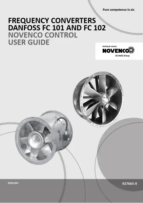
Pure competence in air.927665-0FREQUENCY CONVERTERS DANFOSS FC 101 AND FC 102NOVENCO CONTROL USER GUIDE927665-0GBFrequency converters Danfoss FC 101 and FC 102Novenco control user guideContents1.General2.Wire configuration3.First time run after installation4.Configuration of FC101 converter5.Configuration of FC102 converter6.Modbus configuration7.Reference documentation8.Patents and trademarks9.Declaration of conformity1.GeneralThe procedures in this guide serve as examples of how to control the Danfoss FC 101 and FC 102 frequency con-verters in combination with Novenco fans.Please read all relevant parts of this complete guide.Procedures and methods in this guide should be fol-lowed for the warranty to remain valid.2.Wire configurationCheck wires are correctly connected•Check that a wire connects the terminals no. 12 and 27 in the frequency converter.•Connect a control wire to terminal no. 18 in the fre-quency converter. The terminal must pull high (24V) to activate the converter.•Check the signal wire is connected to terminal no. 53. For voltage control the signal levels are 0 - 10V and for current control the levels are 4 - 20mA.•Check that ground is connected to terminals no. 20 and 55.Table 1.Icons in guideFigure 2Terminal block set up for current control3.First time run after installationHow to check the installation is correct1.Check the installation is powered off on the mainswitch.2.Check the fan and frequency converter are in-stalled correctly. Refer to the installation and maintenance guides for the fan and frequency converter.3.Power on the installation at the main switch. Thefrequency converter starts in idle mode.4.Push Hand On on the local control panel (LCP)on the frequency converter. This activates the fan rotor.5.Check the direction of rotation is consistent withthe arrows on the fan casing.6.Turn off the installation at the main switch.7.Connect the start signal wire to terminal no. 18.8.Voltage or current mode:Connect the reference wire to terminal no. 53.Modbus mode:Connect the reference wires to terminals no. 68 and 69.4.Configuration of FC101 converterThe converter is set up for voltage mode as standard. The minimum speed is indicated with 0V and the max-imum speed with 10V.Figure 3Wire diagram for the FC101+10 V DC4.1Change from voltage to current con-trolHow to change the FC101 to current control1.Push the Menu button on the LCP on the fre-quency converter.2.Push the ↓ and ↑ buttons to navigate to the Wiz-ard. Push OK to select.3.Push ↓ to navigate to the following menu item.6-19 Terminal 53 mode[1] Voltage mode4.Push OK to access and use the ↓ and ↑ to selectcurrent mode.5.Push OK to accept.The frequency converter now operates in current mode for control signals. The minimum speed is indicated with 4mA and the maximum speed with 20mA.5.Configuration of FC102 converter The converter is set up for voltage mode as standard.The minimum speed is indicated with 0V and the max-imum speed with 10V.Figure 4Wire diagram for the FC1025.1Change from voltage to current con-trolHow to change the FC102 to current control1.Remove the screw that holds the lid on the fre-quency converter.2.Pull out the LCP with a straight pull.3.Locate the text A53 U - I.4.Push the button from position U to I with ascrewdriver.5.Put the LCP back.6.Attach the lid and insert the screw.The frequency converter now operates in current mode for control signals. The minimum speed is indicated with 4mA and the maximum speed with 20mA. 6.Modbus configurationAll parameters are accessible through Modbus RTU (Re-mote Terminal Unit) either directly or via PCD (Process Data).To setup the Modbus RTU1.Push the Menu button two times.2.Push ↓ to navigate to8-** Comm. and Options.3.Push OK.4.Push ↓ to navigate to 8-3 FC port settings.5.Push OK.6.Push OK again.7.Push ↓ to navigate to [2] Modbus RTU.8.Push OK to confirm.9.Push ↓ to navigate down and check the followingsettings.•Address•Baud Rate•Parity / Stop bit•Minimum Response Delay•Maximum Inter-char..10.Push OK to select, the ↓ and ↑ buttons to changeand push OK to confirm settings.Write and start-stop notes•PCD: It is possible to configure up to 64 parame-ters in PCDs.Write PCDs in par. 8-42.xx, and read PCDs in par.8-43.xx. These PCDs are accessible via holdingregisters 28xx and 29xx.•Write control word: Par. 8-42.0 and par. 8-42.1 areset to the control word and as reference, respec-tively. Set par. 8-42[2-63] to the par. no. to write to.•Start-stop: Write the control word to register 2810to start or stop the converter.Read notes•The reference register is 2811 with 0 - 4000hex(0-100%).•Read status word: Par. 8-43.0 and par. 8-43.1 areset to status word and main actual value, respec-tively. Set par. 8-43[2-63] to the par. no. to readfrom.Figure 5Location of terminal 53Bit Bit value = 0Bit value = 100Reference value External selection LSB01Reference value External selection MSB02DC brake Ramp03Coasting No coasting04Quick stop Ramp05Hold output frequency Use ramp06Ramp stop Start07No function Rest08No function Jog09Ramp 1Ramp 210Data invalid Data valid11Relay 01 open Relay 01 active12Relay 02 open Relay 02 active13Parameter set-up Selection LSB14< Not used >< Not used >15No function ReverseTable 2.Control word bit positions•Read status word: Read the status word from reg-ister 2910.Other notes•Set the speed, i.e. the main actual value, with reg-ister 2911.•Read the configuration of par. 8-43.3.. with regis-ter 2912.•To configure a PCD to read a 32bit parameter re-quires configuration of two consecutive PCDs to the same parameter. For example, the parameter 16-10 Power [kW] is a 32bit integer, which may be configured in par. 8-43.2 and 8-43-3, or par. 8-43.4 and 8-43.5 and so on.The sizes of the different parameters are available in the programming guide.•To address parameters directly use the register no. = parameter no. x 10. For example, the par. 16-90 is accessible via register no 16900.•Some PLCs have 0 offsets, which means the value 1 must be subtracted from the register no. For ex-ample, reg. 2810 is 2809 etc.00Control not ready Control ready 01Drive not ready Drive ready 02Coasting Enable 03No error Trip04No error Error (no trip)05Reserved -06No error Triplock 07No warningWarning08Speed reference Speed = reference 09Local operationBus control10Out of frequency limit Frequency limit ok 11No operation On operation12Drive ok Stopped, auto start 13Voltage ok Voltage exceeded 14Torque ok Torque exceeded 15Timer okTimer exceededTable 3.Status word bit positionsNovenco Building & Industry A/S Industrivej 22Tel. +45 70 77 88 994700 Naestved Denmark7.Reference documentation•Danfoss Operating guideVLT ® HVAC basic drive FC 101Publication no. MG18AA02, 04/2018•Danfoss Programming guide VLT ® HVAC basic drive FC 101Publication no. MG18B502, 04/2018•Danfoss Design guideVLT ® HVAC basic drive FC 101Publication no. MG18C802, 04/2018•Danfoss Operating guide VLT ® HVAC drive FC 102Publication no. MG16O202, 04/2018•Danfoss Programming guide VLT ® HVAC drive FC 102Publication no. MG11CE02, 03/2015•Danfoss Design guide VLT ® HVAC drive FC 102Publication no. MG11BC02, 06/20148.Patents and trademarksNovenco ®ZerAx ® is a registered trademark of Novenco Building & Industry A/S.AirBox™ and NovAx™ are trademarks of Novenco Building & Industry A/S.VLT ® is a registered trademark of Danfoss A/S.The ZerAx ® processes of manufacture, technologies and designs are patented by Novenco A/S or Novenco Building & Industry A/S.Pending patents include Brazil no. BR-11-2012-008607-3, BR-11-2012-008543-3, BR-11-2012-008545-0, BR-11-2014-002282-8 and BR-11-2014-002426-0; India no. 4140/CHENP/2012, 4077/CHENP/2012, 821/CHENP/2014 and 825/CHENP/2014; PCT no. EP2012/064908 and EP2012/064928; South Korea no. 10-2012-7012154.Granted patents include Canada no. 2.777.140,2.777.141, 2.777.144, 2.832.131 and 2.843.132; China no. ZL2010800458842, ZL2010800460965, ZL2010800464275 and ZL2012800387210; EU no. 2488759, 2488760,2488761, 2739860 and 2739861; India no. 312464; South Korea no. 10-1907239, 10-1933724, 10-1980600 and 10-2011515; US no. 8.967.983, 9.200.641, 9.273.696 B2,9.683.577 and 9.926.943 B2. Granted designs include Bra-zil no. BR-30-2012-003932-0; Canada no. 146333; China no. 1514732, 1517779, 1515003, 1555664 and 2312963; EU no. 001622945-0001 to 001622945-0009 and 001985391 - 0001; India no. 246293; South Korea no. 30-0735804; US no. D665895S, D683840S, D692119S, D704323S,D712023S, D743018S, D755363S, D756500S, D821560S and D823452S.The NovAx Basic jet fans manufacturing processes, technologies and designs are patented by Novenco A/S or Novenco Building & Industry A/S.Granted patents include EU no. 2387670 and United Arab Emirates no. 1372. Granted designs include EU no. 001069884-0003, 001069884-0008, 001069884-0010, 001069884-0013, 001069884-0017, 001069884-0019, 001069884-0022, 001069884-0026 and 001069884-0028; United Arab Emirates no. D223/2009.The CGF jet fans designs are patented by Novenco A/S or Novenco Building & Industry A/S.Granted designs include EU no. 001610643-0001 to 001610643-0005.Copyright © 2016 - 2020,Novenco Building & Industry A/S.All rights are reserved.9.Declaration of conformityRefer to the declaration information in the documenta-tion for the fans and frequency converters.Figure 6QR code to this guide onPure competence in air. ttt͘EKs E Kͳ h/> /E'͘ KD。
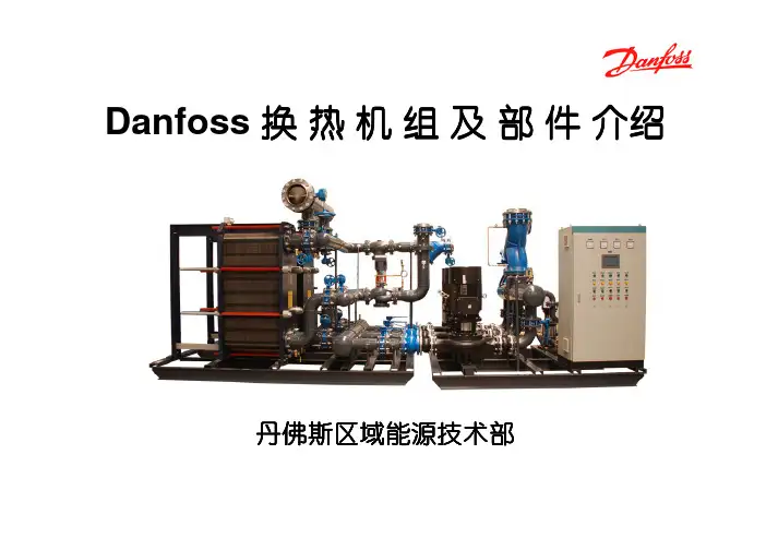
Danfoss 换热机组及部件介绍丹佛斯区域能源技术部户用小型换热机组多户用小型换热机组大型换热机组中型换热机组Danfoss 机组产品全系列机组产品全系列、、多功能设计通常要考虑设计通常要考虑::机组本身热负荷参数等 机组整体结构 客户特殊需求,如布置空间、噪音等 机组所处热力系统的水力工况设计方案量体裁衣设计方案量体裁衣,,关注客户利益机组优化设计软件机组优化设计软件,,资深的专业技术人员三维三维设计设计设计,,结构紧凑结构紧凑,,优化布局优化布局,,维修方便优化的专业设计着重细节着重细节,,追求完美细微之处见真功细微之处见真功,,Danfoss 的设计细致到每个细节的设计细致到每个细节,,精益求精精益求精。
精心选择测点位置精心选择测点位置,,保证数据采集真实准确排气装置排污装置卸压装置完备的排气完备的排气、、排污及安全卸压装置排污及安全卸压装置,,保证机组稳定运行着重细节着重细节,,追求完美细微之处见真功细微之处见真功,,Danfoss 的设计细致到每个细节的设计细致到每个细节,,精益求精精益求精。
着重细节着重细节,,追求完美细微之处见真功细微之处见真功,,Danfoss 的设计细致到每个细节的设计细致到每个细节,,精益求精精益求精。
过滤器本体具有压差检测功能过滤器的精巧设计,使得压差检测功能变得简单容易恶劣水力工况下,采用压差控制装置确保机组的温度稳定调节。
机组配置80%以上是 以上是Danfoss产品 机组配置 以上是 产品Danfoss换热器Danfoss电动调节阀Danfoss ECL 控制器Danfoss温度/压力传感器Danfoss超声波热量表Danfoss球阀Danfoss变频器Grundfos水泵Danfoss板式换热器 板式换热器• 板片厚度:0.5mm • 沟槽深度:2.8~3.9mm • 板片材质:AISI304 AISI316 • 密封垫片:NBR(丁晴) EPDM(三元乙丙) • 接口尺寸:DN32~DN300 • 接口方式:螺纹连接 法兰连接Danfoss板式换热器 板式换热器方便安装的免粘接垫片 独特的定位系统一次冲压成形确 保板片精度独特的紧固螺栓设计 卓越的导流区设计Danfoss球阀 球阀• 免维护 • 阀体为整体焊接件,易打开和关闭 • 阀门关闭严密,操作轴密封严密 • 低阻力,减少水泵能耗操作轴处的密封严密 阀门关闭严密Danfoss电动调节阀 电动调节阀• 流通能力高 • 流量特性为等百分比特性,控制性能好 • 有自检阀门行程的功能, 减少调试时工作量 • 泄漏率低 • 易于安装和操作 • 可手动操作(电手动和机械手动) • 最大口径达到DN250,最高耐温可达350℃ • 可实现控制信号分割功能 • 故障自诊断功能Danfoss电动调节阀 电动调节阀驱动器功能(AME 10/20/30/15/25/35/55/85系列 系列) 驱动器功能 系列U 2V...---V Direct 0(2)V...5(6)V Proportional LOG. flow 100% Kvs Reset1 2 3 4 5 6 7 8 9---I 0V...---V Inverse Sequential 5(6)V...10V 3 point / RL LIN. flow Red. Kvs ResetDanfoss电动调节阀 电动调节阀I• 控制信号的选择 • 控制信号起点 • 正反向动作A A B A B A B AB1U1A BA BABBABABAAB B2 (0)10V4 (0)UI20mA0V...---V0V...---VInverse11112V...---V2V...---VDirectABABABABA BABA BABA BABA BABABABABABA BABAAB BA BABAAB B0 02 410 20V mA0 010 20V mA0 010 20V mA0 0DirectInverse10 20V mADanfoss电动调节阀 电动调节阀•控制信号分割功能当两个调节阀并联时Sequential 5(6)V...10V Sequential 5(6)V...10V1A B A B AB A B A AB B1---0(2)V...5(6)VABA BABABA BAB0 05 1010 20V mA0 05 100(2)V...5(6)V---10 20V mADanfoss电动调节阀 电动调节阀• 模拟量控制和三点控制合为一体 AMV,AME3 point / RL 3 point / RL6A B6ProportionalAB24VACA BABA BABABABProportional24VACA B AB A AB B0 010 20V mADanfoss电动调节阀 电动调节阀• 改变阀门特性功能线性、等百分比特性LIN. flow77A BLOG. flowABA BABA BABABABA BABAAB B0 010 20V mA0 0LOG. flowLIN. flow10 20V mADanfoss电动调节阀 电动调节阀• Kvs值限制功能DN125 Kvs=220 DN150 Kvs=320 计算Kv=270? 建议当所选调节阀的Kvs值大于计算Kv 值20%以上时应用此功能Red. Kvs81A B8100% KvsABA BABAAB B100% Kvs100% KvsRed. Kvs82% KvsABABA BABAAB B0 010 20V mA0 010 20V mADanfoss压差控制器 压差控制器压差控制器工作原理MDV压差控制器是在水系统中用来保持某两点间压 差恒定的自力式控制阀,一般由阀体,驱动膜盒, 导压管等部分组成. 其工作原理如左图所示(左图为压差控制器控 制电动调节阀两端的压差): 电动调节阀(MDV)上游的高压通过导压管引 导至控制膜盒下侧. 电动调节阀下游的压力通过外部导压管或内部 导压孔引导至控制膜盒上侧. 由压差引起的作用力与内部弹簧的作用力相互 平衡,使调节阀两端的压差保持恒定.压差控制器侧压高侧压中侧压低调节弹簧的预紧力,即可调节压差设定值.Danfoss压差控制器 压差控制器为什么使用差压控制器?• 保持电调阀两端压差恒定——保证调节阀的调节特性,使控温准确 ——减少调节阀动作次数,延长使用寿命 ——限制全开时最大流量,反之全开时近端热站 局部“抢水”(热权度小于1)• 保证电调阀在较低的压差下工作——防止电调阀两端压差超过其最大关闭压差 ——防止出现气穴现象,降低噪音Danfoss变频器 变频器FC100系列 变频器 系列• 专为水泵、风机的应用而设计制造 • 电压矢量控制模式 • 优化的谐波性能,内置双直流电抗器 • 最佳的EMC特性,内置射频干扰滤波器 • 自动能量优化功能 • 电机自适应功能 • 双通道PID调节 • 电机友好性 • 完全的自身及电机保护 • 水泵专用功能管网水力补偿功能/无流量检测功能/睡眠功能降低能源消耗 降低噪音 水泵与管道寿命长 水泄漏降至最低Danfoss ECL控制器 控制器专用于供热和暖通空调系统的控制器 – ECL200/300 1. 使用简单, 调试时只需设定即可, 勿需任何编程 2. 操作方便, 只需简单培训工人即可操作 3. 安装简便, 运行可靠性高 4. 性价比高功能强大的可编程控制器 – ECL Apex 20 1. 使用灵活, 扩展性强 2. 组网方便, 本地化的HMI界面Danfoss ECL控制器 控制器• 气候补偿 • 分时控温 • 一次网回水温度限制 • 优化控制 • 室内温度影响ECL 200/300•功能专一,使用方便简单 • 气候补偿供暖控制或生活热水恒温控制, 根据室外温度 调节供水温度,节能舒适. •分时供暖 •PI 控制,三点可控硅输出。
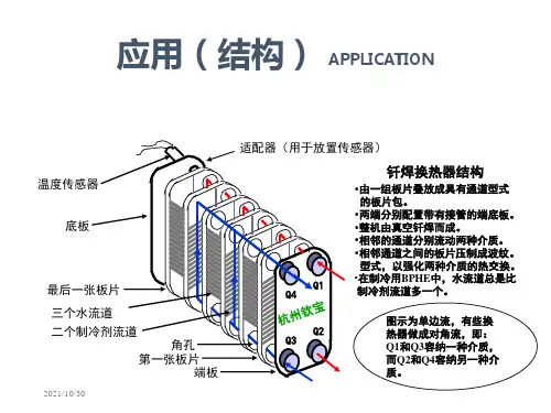


板式换热器培训教材编制:审核:批准:姚电检修田湾项目部静机专业一、作用及功能板式换热器是由框架和板束组成,传热板片和密封垫片组成板束,传热板片四角开有角孔,密封垫片和传热板片安装在固定压紧板和活动压紧板之间的框架内。
工作介质分别在两相邻的传热板片所形成的狭窄而曲折的通道中流过,冷、热介质依次通过各个流道,中间隔一层传热板片,冷、热介质的传热过程实际上就是热介质的热能传递给冷介质的过程。
在此过程中温度较高的热介质通过传热板片将热能传递给温度较低的冷介质,温度较高的热介被冷却,热能减少;温度较低的冷介质被加热,热能增加。
通过热能转移来实现热工工艺的要求。
二、结构特点板式换热器是由许多波纹形的传热板片,按一定的间隔,通过橡胶垫片压紧组成的可拆卸的换热设备。
板片组装时,两组交替排列,板与板之间用粘结剂把橡胶密封板条固定好,其作用是防止流体泄漏并使两板之间形成狭窄的网形流道,换热板片压成各种波纹形,以增加换热板片面积和刚性,并能使流体在低流速成下形成湍流,以达到强化传热的效果。
板上的四个角孔,形成了流体的分配管和泄集管,两种换热介质分别流入各自流道,形成逆流或并流通过每个板片进行热量的交换。
(一)板式换热器的优点:(1)体积小,占地面积少;(2)传热效率高;(3)组装灵活;(4)金属消耗量低;(5)热损失小;(6)拆卸、清洗、检修方便;(二)板式换热器的缺点:板式换热器缺点是密封周边较长,容易泄漏,使用温度只能低于150℃,承受压差较小,处理量较小,一旦发现板片结垢必须拆开清洗。
三、技术参数板式换热器是将薄的金属板片(一般0.4~0.8mm的不锈钢板)冲压成为波纹状,周边卡扣或张贴合成橡胶类的密封垫片,每一张传热板片为一个传热单元,板片两侧的高温流体和低温流体在板片和密封垫片组成的空间里对流或并流进行热交换。
通过上下两根拉杆将传热部分固定在固定板(框架板)和活动板之间,并用长的螺栓紧固。
⑴单板计算换热面积a—在垫片内侧参与换热部分的板片展开面积,按下式计算:a = φ·a1式中a—单板计算换热面积,m2;φ—展开系数,板片展开面积与投影面积之比,按下式计算:φ= (φ≈1.15~1.3,一般φ≈1.2)式中t′—波纹节距展开长度,mm;t —波纹节距,mm;a1 —在垫片内侧参与换热部分的板片投影面积,m2。

操作手册Lit. Code200000279-2-ZH-CN由...出版阿法拉伐 Lund AB箱74参观:Rudeboksvägen 1226 55 Lund, 瑞典+46 46 36 65 00+46 46 30 50 90******************The original instructions are in English© Alfa Laval Corporate AB 2019-11本文件及其内容受阿法拉伐集团公司拥有的著作权及其他知识产权权利的保护。
未经阿法拉伐集团公司的事先明确书面许可,任何人不得以任何形式或通过任何方式,或出于任何目的,复制、重新制作或传输本文件的任何内容。
本文件所提供的信息和服务仅为用户提供便利和服务,对该信息和服务的准确性和适用性不做出于任何目的的陈述或保证。
保留所有权利。
EnglishDownload local language versions of this instruction manual from /gphe-manuals or use the QR codeбългарскиИзтеглете версиите на това ръководство заупотреба на местния език от / gphe-manuals или използвайте QR кода.ČeskýStáhněte si místní jazykovou verzi tohoto návodu k obsluze z /gphe-manuals nebo použijte QR kód.DanskHent lokale sprogversioner af denne brugervejledning på /gphe-manuals eller brug QR-koden.DeutschSie können die landessprachlichen Versionen dieses Handbuch von der Website /gphe-manuals oder über den QR-Code herunterladen.ελληνικάΠραγματοποιήστε λήψη εκδόσεων του παρόντοςεγχειριδίου οδηγιών σε τοπική γλώσσα από το/gphe-manuals ή χρησιμοποιήστετον κωδικό QR.EspañolDescárguese la versión de este Manual de instrucciones en su idioma local desde/gphe-manualso utilice el código QR.EestiSelle kasutusjuhendi kohaliku keele versiooni saate alla laadida lingilt /gphe-manuals või kasutades QR-koodi.SuomalainenLaitaa tämän käyttöohjeen suomenkielinen versio osoitteesta /gphe-manuals tai QR-koodilla.FrançaisTéléchargez des versions de ce manuel d’instructions en différentes langues sur /gphe-manuals ou utilisez le code QR.HrvatskiPreuzmite lokalne verzije jezika ovog korisničkog priručnika na poveznici /gphe-manuals ili upotrijebite QR kod.MagyarAz Ön nyelvére lefordított használati útmutatótletöltheti a /gphe-manuals weboldalról, vagy használja a QR-kódot.ItalianoScarica la versione in lingua locale del manuale di istruzioni da /gphe-manuals oppure utilizza il codice QR.日本の/gphe-manuals からご自分の言語の取扱説明書をダウンロードするか、QRコードをお使いください。
User manualInstallation, Operation and Maintenance ManualAPP pumps (APP 21-43)Service guideMicroChannel Heat Exchangers MCHEInstallation and Maintenance Guide Sevice guide | Application, Installation and Maintenance Manual MCHE2 |AX292455807588en-000101 | 01.2019Table of ContentsTable of Contents . . . . . . . . . . . . . . . . . . . . . . . . . . . . . . . . . . . . . . . . . . . . . . . . . . . . . . . . . . . . . . . . . . . . . . . . . . . . . . . . . .21 . Introduction . . . . . . . . . . . . . . . . . . . . . . . . . . . . . . . . . . . . . . . . . . . . . . . . . . . . . . . . . . . . . . . . . . . . . . . . . . . .41 .1 G eneral . . . . . . . . . . . . . . . . . . . . . . . . . . . . . . . . . . . . . . . . . . . . . . . . . . . . . . . . . . . . . . . . . . . . . . . . . . . . . . . . .41 .2 Symbols . . . . . . . . . . . . . . . . . . . . . . . . . . . . . . . . . . . . . . . . . . . . . . . . . . . . . . . . . . . . . . . . . . . . . . . . . . . . . . . .42 . Storage and working environments . . . . . . . . . . . . . . . . . . . . . . . . . . . . . . . . . . . . . . . . . . . . . . . . . . . . .52 .1 Storage . . . . . . . . . . . . . . . . . . . . . . . . . . . . . . . . . . . . . . . . . . . . . . . . . . . . . . . . . . . . . . . . . . . . . . . . . . . . . . . .52 .2 Handling . . . . . . . . . . . . . . . . . . . . . . . . . . . . . . . . . . . . . . . . . . . . . . . . . . . . . . . . . . . . . . . . . . . . . . . . . . . . . . .52 .3 Bending procedure . . . . . . . . . . . . . . . . . . . . . . . . . . . . . . . . . . . . . . . . . . . . . . . . . . . . . . . . . . . . . . . . . . . . .53 . Installation . . . . . . . . . . . . . . . . . . . . . . . . . . . . . . . . . . . . . . . . . . . . . . . . . . . . . . . . . . . . . . . . . . . . . . . . . . . . . .63 .1 Pass arrangement . . . . . . . . . . . . . . . . . . . . . . . . . . . . . . . . . . . . . . . . . . . . . . . . . . . . . . . . . . . . . . . . . . . . . .63 .2 Fan location and size . . . . . . . . . . . . . . . . . . . . . . . . . . . . . . . . . . . . . . . . . . . . . . . . . . . . . . . . . . . . . . . . . . . .63 .3 Coil mounting against thermal expansion . . . . . . . . . . . . . . . . . . . . . . . . . . . . . . . . . . . . . . . . . . . . . . .73 .4 Elimination of gaps . . . . . . . . . . . . . . . . . . . . . . . . . . . . . . . . . . . . . . . . . . . . . . . . . . . . . . . . . . . . . . . . . . . . . .83 .5 Prevention of galvanic corrosion . . . . . . . . . . . . . . . . . . . . . . . . . . . . . . . . . . . . . . . . . . . . . . . . . . . . . . . . .83 .6 Vibration . . . . . . . . . . . . . . . . . . . . . . . . . . . . . . . . . . . . . . . . . . . . . . . . . . . . . . . . . . . . . . . . . . . . . . . . . . . . . . .94 .Leak repair . . . . . . . . . . . . . . . . . . . . . . . . . . . . . . . . . . . . . . . . . . . . . . . . . . . . . . . . . . . . . . . . . . . . . . . . . . . . . .95 . Coating . . . . . . . . . . . . . . . . . . . . . . . . . . . . . . . . . . . . . . . . . . . . . . . . . . . . . . . . . . . . . . . . . . . . . . . . . . . . . . . .106 Maintenance . . . . . . . . . . . . . . . . . . . . . . . . . . . . . . . . . . . . . . . . . . . . . . . . . . . . . . . . . . . . . . . . . . . . . . . . . . .106 .1 Filters . . . . . . . . . . . . . . . . . . . . . . . . . . . . . . . . . . . . . . . . . . . . . . . . . . . . . . . . . . . . . . . . . . . . . . . . . . . . . . . . . .106 .2 Shut down periods . . . . . . . . . . . . . . . . . . . . . . . . . . . . . . . . . . . . . . . . . . . . . . . . . . . . . . . . . . . . . . . . . . . . .106 .3 Cleaning procedure . . . . . . . . . . . . . . . . . . . . . . . . . . . . . . . . . . . . . . . . . . . . . . . . . . . . . . . . . . . . . . . . . . ..10Service guide | Application, Installation and Maintenance Manual MCHE3AX292455807588en-000101 | 01.2019 |1.1 Gener a lThis guide is for installation and maintenance of Danfoss Microchannel Heat Exchangers (MCHEs) . We recommend that you read this manual carefully before commencing any work .Danfoss is not responsible or liable for any damage caused by failure to comply with the instructions in this manual and/or due to incorrect installation, operation and mainte-nance of MCHEs .All personnel being responsible for operation and maintenance of theeat exchanger unit must read and fully understand these instruc-tions before:• Transportation of the MCHE unit • Lifting the unit• Installing the MCHE unit •S ervicing the MCHE unit • Maintaining the MVHe unit•1.2 Gener alI ndicates something to be noted by thereaderI ndicates a situation which will or could result in personal injury and/or damage to the MCHE1. IntroductionSevice guide | Application, Installation and Maintenance Manual MCHE4 |AX292455807588en-000101 | 01.20192. Storage and workingenvironments• Microchannel heat exchangers should bestored indoors in a dry and clean environ-ment .• The storage temperature range is -40 °C to 121°C (-40°F to 250°F) .•Metal chips, and/or copper or steel dust can cause galvanic corrosion, so storage and installation areas must remain clean and separate from machining or welding areas . Use separate tools and/or keep tools clean .•To minimize potential damage, we recom-mend that you keep MCHEs in their original packaging until they are installed in the air conditioning or refrigeration equipment . •Improper storage and stacking of MCHEs can cause premature corrosion or deforma-tion and will reduce MCHE’s life . Extra care should be taken when storing MCHEs!• Refrigerants used in MCHE shall comply with AHRI Standard 700 .•The maximum operating pressure shall not exceed the value shown on the Label of MCHE .2.1 Stor a ge2.2 H a ndlingCompared to tube & fin coils, microchannel heat exchangers are relatively light, the fins are harder to bend and they are less likely to cut fingers . The combination of these features makes MCHEs easier to handle than tube & fin coils . However, the overall coil assembly is made of soft alu-minum, so it is susceptible to deformation (Fig .1)Fig . 1 Handling attentions2.3 Bending procedureThe same bending machines can be used for MCHE and tube & fin heat exchangers . In order to optimize costs associated with shipping and packaging, we recommend that MCHEs be shipped flat and formed at the customer’s location .Bending Radius:The minimum bend radius required to achieve acceptable manufacturing yields is a function of the microchannel tube, fin, and alloy, the overall capabilities of the bending equipment including, fixturing, bending speed and bending length .NOTE: Conducting trial bending runs of thespecific coil and configuration are recommended to verify . In general, tighter radius, thicker tubes and longer bend lines are harder to bend . Use a larger radius if possible .Recommended minimum bending radii (as determined by factory tests under favorable conditions) are shown in Table 1 for different microchannel tubes and fins . Consult with Danfoss for the tubes not listed . Do notarbitrarily extrapolate or interpolate the values .•Never lift a MCHE by the inlet and outlet tubes as it might result in dimensional deviation or worse yet, the initiation of a crack that can later result in a leak .• Do not hit or drop MCHE on edges . The MCHE is constructed of soft aluminum therefore, dropping, striking, placing heavy objects on top of, or stepping on any part of the heat exchanger will likely cause a deformation . If the coil becomes slightly deformed or bowed, it is possible to flatten them back out by laying them concave side down on a flat hard surface and applying pressure via a large heavy flat plate (say 3-4 square feet of ½” non-metallic sheet, such as plywood or plastic, with a couple of handles attached) . This procedure works for bowed coils with flush fins, but not for local fin protrusions .Table 1Service guide | Application, Installation and Maintenance Manual MCHE5AX292455807588en-000101 | 01.2019 |Consider the following during bending:• MCHEs are constructed of soft aluminumand are susceptible to deformation during handling . Prior to bending operation, make sure the MCHE is flat, square and undam-aged . Consider a sizing operation to ensure this .• Make sure the coils are loaded into thebender in a way that keeps them flat square and undamaged . • Keep the flat tubes perpendicular to thespindle while bending the coil .• Clamp the coil during the bending process,being careful not to crush it . • Slower bending speeds will often yieldbetter results .• Vertical spindle bending machines are oftenset up so that the microchannel coil ends up sliding along the table with all its weight supported by the header ends and/or the bottom dead tube .During the bending operation, do not let one end of the coil become cantilevered off the edge the table, because this can cause the coil to droop with the tubes being non-perpendicular to the spindle, resulting in corkscrewing or reduced bend quality and/or consistency . Note that with some benders, a portion of the supporting table will drop down during bending, creating opportunities for cantilever loads and improper bending .•Bending multi-bend coils on a horizontal spindle bender can cause cantilevered loads resulting from the dead weight of the unsupported bent legs . As an example, a coil with three (3) bends, depending on fixturing, may result in the load of the first 75% of the coil being transferred into the remaining coil leg, possibly causing poor bend quality and/or permanent deforma tion . Bending challenges are greater with MCHE’s than similar fin and tube coils, requiring proper fixturing .3. Inst a ll a tion 3.1 Pass arrangementCarefully identify the locations of the inlet andoutlet tubes . Microchannel condensers is often designed with multiple passages (parallel flow) that have fewer tubes in each successive pass (Fig . 2)Danfoss MCHEs include a small notch in both headers to indicate that this is the bottom of the heat exchanger . Additionally, a product label is placed on the outermost tube (unless specified elsewhere by the customer), indicating the top of the heat exchanger .Incorrectly connecting the inlet and outlet tubes of a MCHE will likely result in excessive refrige-rant side pressure drop and poor heat transfer .Fig . 2 MCHE passes distribution3.2 Fan location and sizeAir distribution may have an influence on the performance of the MCHE . For good air distribu-tion choosing a fan with proper fan diameter and keeping a constant distance between the coil and the fan is desirable . We recommend selecting a fan diameter that is as close as possible to the smallest of MCHE height and length . The distance between MCHE and fan is )recommended to be at least 15 times the width/depth of MCHE coil when possible (Fig .3) .Fig . 3 Fan location and sizeSevice guide | Application, Installation and Maintenance Manual MCHE6 |AX292455807588en-000101 | 01.20193.3 Coil mounting against thermal expan- sionThermal expansion of aluminum is higher than most other metals . Frequent thermally induced stress could shorten the life of the micro channel heat exchanger (Fig .4)Fig . 4 Coil mounting for MCHETo avoid the risk of thermal expansion, a micro channel heat exchanger must be mounted with brackets that allow some flexibility of movement . Mounting methods as indicated in Figures 5a and 5b are recommended .Fig . 5b Mounting by end plateInlet/outlet connections are not designed to be used as handles, support mating tubes, resist with mating tubes during assembly, etc . In particular:• not exposed to stress/tension . (Fig .6)aluminum inlet/outlet tubes and/orforcing is required during installation .Fig .6 Inlet/Outlet connection attentionsService guide | Application, Installation and Maintenance Manual MCHE7AX292455807588en-000101 | 01.2019 |Plastic heat shrink tubing prevents galvanic corrosion in the MCHE’s copper to aluminum joint by keeping moisture from entering the area . A minimum of 70mm length from the Cu/Al joint to the connection point is required to protect the Cu-Al brazing joint and plastic shrink tube from excessive heat during the brazing process . When brazing copper piping to the MCHE, it is recom-mended to use dry nitrogen purging along with a heat sink and/or wrapping the copper stub tube with a wet cloth to protect the Cu/Al joint and heat shrink tubing from excessive heat . This also applies to microchannel heat exchangers with aluminum inlet/outlet tubes . Depending on the location of the connections relative to the heat exchanger, a heat shield may be required to protect the MCHE’s tubes and fins from the brazing torch . The recommended pipe length “L” after the brazing joint should be greater than or equal to 70mm as shown in the picture below (Fig .7) .Fig . 7 Recommended length of inlet/outletconnections3.4 Elimination of gapsTo maximize heat transfer performance, gaps should be eliminated on both sides of the face of the MCHE . Gaps should also be eliminated on the top, bottom and sides of the MCHE so that all fan induced air is directed over the coil surface . This can be accomplished with sealing strips as shown in Fig . 8 .Fig . 8 Typical installation3.5 Prevention of galvanic corrosion Aluminum is a chemically reactive metal and will corrode when combined with most metals that are used today in industrial manufacturing . To avoid any galvanic corrosion, it is necessary to separate Al and other metals . The best way to prevent galvanic corrosion is to use plastic/rubber/foam as a means to isolate the aluminum coil from dissimilar metals (Fig 8)Sevice guide | Application, Installation and Maintenance Manual MCHE8 |AX292455807588en-000101 | 01.20193.6 Vibr a tionVibration that exceeds a specific range maycause the failure of MCHE . To avoid failure due to vibration:•Make sure vibration level meet require-ments as in table 2 .Table 2 The allowable vibration rangesService guide | Application, Installation and Maintenance Manual MCHE9AX292455807588en-000101 | 01.2019 |5. Co a tingCoating of a heat exchanger could increase corrosion resistance in certain applications and/or environmental conditions such as coastal or industrial areas, as well as situations with stagnant water or extreme wet conditions . Danfoss approved coating systems provide a controlled process for the cleaning, rinsing, and the application of the coating material with full and even coverage . Untested coating systems may not adhere properly to the aluminum surface due to the flux residue left on thealuminum surface after brazing . In addition, any small area not covered by the coating couldpotentially pose a risk of failure due to corrosion . Thermal performance may also be reduced by improper application of the coating resulting in clogging or bridging between the fin and louversWARNINGSField applied coatings are not recommended for brazed aluminum MicroChannel heat exchang-ers .Danfoss MicroChannel heat exchangers must NOT be coated using any other coating, but the ones specifically approved by Danfoss, such as certain qualified e-coating (epoxy based electrophoretic coating) suppliers or similar high-quality coating technologies . Coating of a coil using a supplier or coating process notapproved by Danfoss voids the product warranty . It may also reduce the lifetime and/or the performance of the MicroChannel heat exchanger . Consult your Danfoss Sales &Application representative for more information .6. M a inten a nceFrequent servicing is essential to maintainingthe required MCHE performance . For everyinstalled Danfoss MCHE, service records must be documented .CAUTIONPrior to servicing the MCHE, be sure to discon-nect the power supply and use lock-outmethods to prevent the power from acciden-tally being turned on .6.1 FiltersDanfoss recommends the use of air filters on the frontal face of the MCHE to lower the deposition of rain water and other contaminants that can collect on the surface of the tubes .6.2 Shut down periodsDuring periods when the MCHE is not operated for longer than a week, the MCHE must be completely cleaned following the cleaningprocedure . This practice must also be performed during short shut-down periods where corrosive deposits accumulate on the MCHE .6.3 Cleaning procedureRelative to tube & fin heat exchangers, Micro-Channel heat exchanger coils tend to accumu-late more dirt on the surface of the coil and less dirt inside the coil, making them easier to clean . Follow the steps below for proper cleaning:Step 1: Remove surface debrisRemove surface dirt, leaves, fibers, etc . with a vacuum cleaner (preferably with a brush or other soft attachment rather than a metal tube),compressed air blown from the inside out, and/or a soft bristle (not wire!) brush . Do not impact or scrape the coil with the vacuum tube, air nozzle, etc .Step 2: RinseRinse only with water . Do not use any chemicals (including those advertised as coil cleaners) to clean MicroChannel heat exchangers, as they may cause corrosion .Hose the MCHE off gently, preferably from the inside-out and top to bottom, running the water through every fin passage until it comes outclean . The fins of MicroChannel coils are stronger than traditional tube & fin coil fins but still need to be handled with care . Do not hit the coil with the hose . We recommend placing your thumb over the end of the hose rather than using the end of the nozzle to obtain a gentler spray and reduce the possibility of impact damage .We do not recommend using a pressure washer to clean the coil due to the possibility of damage .Warranty claims related to cleaning damage, especially from pressure washers, or corrosion resulting from chemical coil cleaners, will NOT be honored .Step 3: Blow dryDepending on the installation and fin geometry, MicroChannel heat exchangers could possibly retain more water compared to traditional tube & fin coils . It is advised to blow off or vacuum out the residual water from the coil to speed up drying and prevent pooling .Danfoss recommends a quarterly cleaning of the coils, as the minimum . The cleaning frequency should be increased depending on the level of dirt/dust accumulation and the environment (e .g ., coastal areas with chlorides and salts) orindustrial areas with aggressive substances .Danfoss MicroChannel Heat Exchangers (Jia Xing) Co ., Ltd .No . 8, Sangdelan Road, Wuyuan Street,Haiyan, Zhejiang Province314300 P .R . Chinawww .danfoss .com© Danfoss | DCS (im) | 2019.01AX292455807588en-000101 | 10。
板式换热器说明书篇一:板式换热器使用说明书_secret板式换热器使用说明书一、概况板式换热器是液—失情况下,其传热系数比管式换热器高3—5收率可高达90%以上。
板式换热器广泛应用于冶金、石油、化工、食品、制药、船舶、纺织、造纸等行业,是加热、冷却、热回收、快速灭菌等用途的优良设备。
二、结构及外形尺寸BR型系列产品,整机装配有普通式结构(不经常拆洗工况采用)和悬挂式结构(拆洗较频繁的工况采用)两种。
普通式结构由人字形波纹板片、密封垫、压紧板、上下定位螺栓、压紧螺栓等主要零件组成。
悬挂式结构由人字形波纹板片、密封垫、固定压紧板、中间板、活动压紧板、支架、上下定位横梁、压紧螺栓等主要零件组成。
三、技术参数及规格型号表示方法 1、技术参数2、规格型号表示方法:表示:人字形板式换热器,单板片换热面积0.2㎡,经过第一次改型,工作压力1.6Mpa,工作温度150℃,单机公称换热面积20㎡,流程组合形式 2×25 ,式中分子表示热介质,分母表示冷介质,2表示程数有2程,亦为折流次数,25表示每程有25条流道。
四、流程工作原理板式换热器由于板片波纹表面的特殊作用,使流体沿着狭窄弯曲的通道流动其速度的大小方向不断的改变,致使流体在不大的流速下(Rc=200时),激起了强烈端动,因而加快了流体边界层的破坏,强化了传热过程,有效地提高了传热能力。
并使其具有结构紧凑、金优点。
板和B板交替排列,板片间形成网状通道四个角孔形成分配管和汇合管,密封垫把冷热介质密封在换热器里,同时又合理的将冷热介质分开而不致混合。
在通道里面冷热流体间隔流动,可以逆流也可以顺流,在流动过程中冷热流体通过板壁进行热交换。
板式换热器的流程组合形式很多,都是采用不同的换向板片和不同组装来实现的,流程组合形式可分为单流程,多流程和汽液交换流程,混合流程形式。
要根据工艺条件来选择换热器的流程组合。
(图二)五、换热器安装1、板式换热器的两块压紧板上有4个吊耳,供起吊时用,吊绳不得挂在接管、定位横梁或板片上。
01板式换热器概述Chapter定义与原理定义原理结构组成板片密封垫片框架接管工作过程流体进入热量交换流体排出监控与维护02板式换热器性能参数Chapter换热效率换热效率定义01影响因素02提高换热效率的方法03压力损失压力损失定义影响因素降低压力损失的方法传热系数传热系数定义影响因素提高传热系数的方法阻力特性阻力特性定义影响因素降低阻力的方法03板式换热器设计计算Chapter01020304满足工艺要求提高经济性保证安全可靠便于制造、安装和维修设计原则与方法传热计算热负荷计算根据传热学原理,计算换热器的传热系数、传热面积和温差等参数。
压降计算流动阻力计算换热器结构对阻力的影响优化设计策略通过改进换热器结构,提高传热效率,降低流动阻力,减少制造成本。
选用高性能材料,提高换热器的耐腐蚀性、耐高温性和耐压性。
采用先进的制造工艺,提高换热器的制造精度和质量,降低制造成本。
通过改进控制策略,实现换热器的自动调节和优化运行,提高能源利用效率。
结构优化材料优化制造工艺优化控制策略优化04板式换热器选型与应用Chapter01020304根据工艺要求确定换热量、进出口温度等关键参数。
换热需求了解不同板式换热器的传热系数、压力降等性能特点。
设备性能根据介质性质(腐蚀性、温度等)选择合适的板材。
材质选择考虑安装空间及维修便利性,选择合适的设备尺寸。
设备尺寸选型依据及注意事项不同领域应用案例分析01020304化工领域供暖领域空调领域食品工业采用高效传热技术优化设备结构使用可再生能源智能化控制节能环保措施探讨05板式换热器实验操作与技巧Chapter学会板式换热器的安装、调试及操作方法。
培养实验操作能力和团队协作精神。
实验步骤4. 启动实验系统,记录实验数据。
5. 分析实验数据,得出结论。
6. 清理实验现场,整理实验报告。
板式换热器的安装与调试安装前检查板式换热器各部件是否完好,密封件是否老化或损坏。
按照安装图纸将板式换热器安装在指定位置,确保固定牢固,防止运行时产生振动。
丹佛斯钎焊板式换热器说明书
丹佛斯钎焊板式换热器
一、产品简介
丹佛斯钎焊板式换热器是一种紧凑、高效的热传递装置,适用于化工、冶金、电力、造纸等行业中的热交换过程,能够完成液体与液体之间、气体与液体之间、气体与气体之间等多种热交换方式。
该产品采用钎焊技术制作,具有优异的性能和可靠的使用寿命。
二、产品特点
1. 紧凑型结构,占用空间小,重量轻,易于安装和维护。
2. 内部流体采用对流换热方式,换热效率高。
3. 耐腐蚀性能好,适用于恶劣环境下的使用。
4. 单元板式设计,易于清洗和更换。
5. 板式换热器尺寸可根据不同的工况要求进行定制。
三、产品用途
1. 化工行业:用于吸收、脱水、冷却、加热等热传递过程。
2. 冶金行业:用于高温流体的冷却、加热等热传递过程。
3. 电力行业:用于冷却水和循环水之间的热传递。
4. 造纸行业:用于纸浆汁液处理的热传递过程。
四、使用注意事项
1. 在使用前必须仔细阅读本说明书,并按照操作规程正确使用。
2. 定期检查换热器的密封性能和换热效果。
3. 当液体中含有颗粒物质时,应在管道中加装滤网等过滤设备,以免堵塞管道。
4. 当气体中含有腐蚀性气体时,应选用具有良好耐腐蚀性能的材料制作。
5. 在维护时应注意安全,使用保护设备,避免发生意外。
以上是丹佛斯钎焊板式换热器的说明书,如有任何疑问或需要更多详细信息,请联系厂家。
《板式换热器和板式换热装置的技术和应用手册》前言板式换热器和板式换热机组是工业传热过程中必不可少的设备,几乎应用于包括动力、化工、冶金、食品、轻工等一切工业部门;同时,它也是空调、供热中的重要组成部分;在可持续发展的国策下,它还是余热利用、太阳能利用、海水利用、污水利用、地热利用中的关键设备。
随着技术的进步,以及节约资源和能源的紧迫性,近几年来开发了一系列新型的板式换热器,如可拆式、全焊式、钎焊式、板壳式等,并从板式换热器发展至板式换热装置,如蒸发装置、热泵装置、制冷装置、热力机组、催化重整装置、燃气冷凝回收装置等。
适用范围越来越广,需要量越来越多,生产量也越来越高。
但尚没有较完善的新型板式换热器和新型板式换热装置的结构、原理、特性、布置、选型、安装和运行等技术和应用手册。
为了满足市场的需求,为了给工业、空调、供热、新能源利用和余热利用的设计、应用、施工、运行人员提供相关数据和资料,为了给热能工程专业人员提供教材。
成立了由板式换热器专家、板式换热器标准委员会成员、制造专家、专利发明人、设计、施工和用户组成的编委会。
编委会编写本书的原则是为各应用领域的用户、设计、施工、运行人员提供一本技术和应用手册。
既然是一本工具书,内容则必须齐全、精练、简明、实用。
既全又简,既符合科学性,又满足实用性的技术应用手册,使之能真正起到开拓眼界,简化设计计算,提高工作效率,方便实际应用的作用,成为各领域的与换热有关的工程技术人员的得力助手和可靠工具。
本书分为技术篇和应用篇等二篇共十五章。
第一篇主要的内容是提供板式换热器和板式换热装置的基础理论、性能、设计计算方法,性能试验和运行维护,同时也叙述了板式换热器的现况和发展趋势。
第二篇的主要作用是向工业、空调、采暖、新能源等各领域的用户、设计、施工和运行人员介绍了板式换热器和板式换热装置的应用原理和方法。
同时以实例的形式,简明扼要地叙述了应用的方式、设计的方法和节能、经济、环保效益。
板式换热器教案(增加特殊条款)教案板式换热器工作原理及特点解析一、教学目标1.让学生了解板式换热器的基本结构和工作原理。
2.使学生掌握板式换热器的主要特点及其在工业中的应用。
3.培养学生分析问题和解决问题的能力。
二、教学内容1.板式换热器的基本结构2.板式换热器的工作原理3.板式换热器的主要特点4.板式换热器的应用领域三、教学重点与难点1.教学重点:板式换热器的工作原理和主要特点。
2.教学难点:板式换热器内部流动与传热过程的理解。
四、教学方法1.讲授法:讲解板式换热器的基本概念、工作原理和特点。
2.图解法:通过图片和示意图展示板式换热器的结构和流动过程。
3.案例分析法:分析板式换热器在实际工程中的应用实例。
五、教学步骤1.导入新课:简要介绍换热器在工业中的重要性,引出板式换热器。
2.讲解板式换热器的基本结构:板式换热器由一组波纹形的金属板组成,板片之间通过垫片密封,形成流体通道。
冷热流体分别在相邻板片的通道内流动,通过板片进行传热。
3.讲解板式换热器的工作原理:以水-水换热为例,热流体(水)在板式换热器的高温侧流动,冷流体(水)在低温侧流动。
热流体释放热量,温度降低,冷流体吸收热量,温度升高。
通过调整板片数量和排列方式,可以满足不同工况下的换热需求。
4.讲解板式换热器的主要特点:1)高效节能:板式换热器具有极高的传热系数,热损失小,节能效果显著。
2)紧凑结构:板式换热器采用板片叠加结构,占地面积小,安装方便。
3)灵活调节:通过增减板片数量或调整板片排列方式,可以灵活调节换热面积和传热效果。
4)易于清洗和维护:板式换热器拆卸方便,可定期清洗板片,保证换热效果。
5.分析板式换热器的应用领域:板式换热器广泛应用于供暖、空调、化工、食品、制药等行业,特别是在中小型换热场合具有明显优势。
6.总结:回顾本节课的主要内容,强调板式换热器的工作原理、特点和应用领域。
7.作业布置:让学生查阅相关资料,了解板式换热器在我国的应用现状和发展趋势。