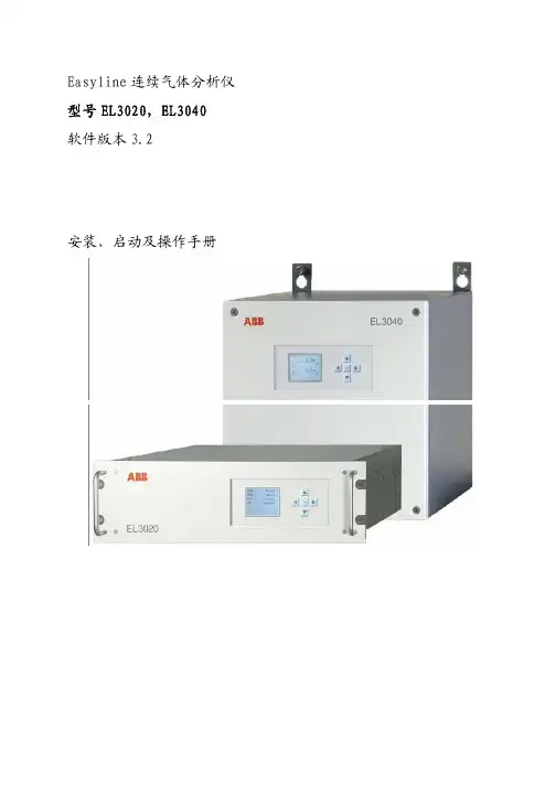
ABB分析仪EL3000系列培训教程
- 格式:ppt
- 大小:8.37 MB
- 文档页数:84

ABB初级培训一、引言随着工业4.0的推进,技术在全球范围内得到了广泛应用,ABB 作为全球领先的工业制造商,其产品在各个领域发挥着重要作用。
为了满足市场需求,培养具备ABB操作与维护能力的专业人才,本初级培训课程应运而生。
本文档将详细介绍ABB初级培训的课程内容、教学方法、培训目标和预期成果。
二、课程内容1.ABB基础知识:介绍ABB的发展历程、产品系列、技术特点和应用领域,使学员对ABB有全面的认识。
2.ABB编程操作:学习ABB的编程方法,掌握RAPID编程语言,熟练操作ABB的示教器,实现的基本运动控制。
3.ABB维护与故障排除:学习ABB的日常维护方法,了解常见故障及排除方法,提高的稳定运行能力。
4.ABB应用案例:分析ABB在不同行业中的应用案例,了解在实际生产中的应用需求和解决方案。
5.实践操作:安排学员在ABB实训基地进行实际操作,提高学员的操作技能和解决实际问题的能力。
三、教学方法1.理论教学:采用多媒体教学方式,结合实际案例,使学员更好地理解ABB的相关理论知识。
2.实践教学:组织学员在ABB实训基地进行实际操作,提高学员的操作技能和解决实际问题的能力。
3.互动教学:鼓励学员提问,讲师现场解答,促进学员对知识的深入理解和掌握。
4.在线学习:提供在线学习资源,方便学员随时查阅资料,巩固所学知识。
四、培训目标1.掌握ABB的基础知识,了解其产品系列、技术特点和应用领域。
2.熟练掌握ABB的编程方法,具备独立编写程序的能力。
3.学会ABB的日常维护和故障排除,提高的稳定运行能力。
4.了解ABB在不同行业中的应用案例,具备一定的项目分析和解决能力。
5.培养具备ABB操作与维护能力的专业人才,满足市场需求。
五、预期成果1.学员完成培训后,具备ABB初级操作与维护能力,可在相关企业从事操作、编程和维护等工作。
2.学员通过培训,提高自身技能水平,为企业的技术升级和产业转型提供人才支持。
3.培训成果的推广与应用,有助于提高我国工业技术应用水平,推动产业升级。
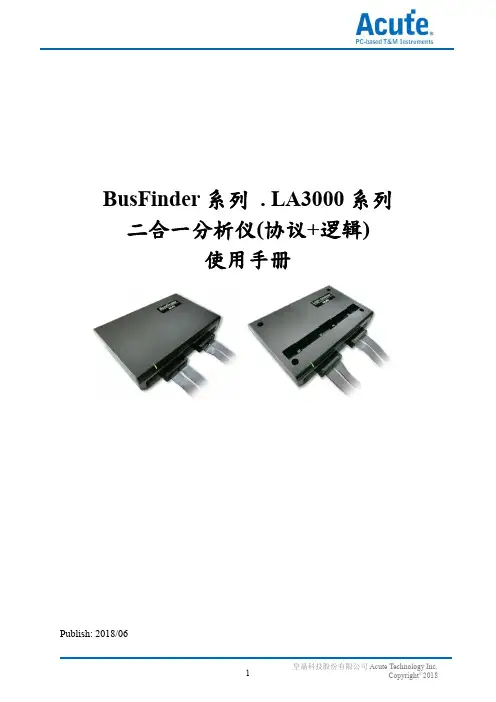
BusFinder系列. LA3000系列二合一分析仪(协议+逻辑)使用手册Publish: 2018/06目录第一章安装与设置 (4)硬件安装 (4)主机外观与功能说明 (4)LA探头 (5)eMMC5.1探头(选配) (6)NAND Flash探头(选配) (7)SD 3.0探头(选配) (8)SD 4.0(uSD 4.0)探头(选配) (9)软件安装 (10)第二章功能列表与操作 (12)协议分析仪 (12)档案 (12)采集 (13)显示波形 (20)搜寻 (20)到末尾 (21)窗口 (21)保存成文本文件 (21)细节窗口 (22)统计窗口 (23)隐藏数据窗口 (23)叠加示波器 (24)光标 (25)逻辑分析仪 (26)档案 (27)采集 (32)采集模式设置 (45)光标 (49)波形区 (52)报告区 (53)总线解碼设置 (54)自定义报告设置 (54)第三章技术支持 (55)附录一探头尺寸规格及脚位定义 (56)LA探头 (56)eMMC5.1探头 (58)NAND Flash探头 (60)SD3.0探头 (61)SD4.0(uSD4.0)探头 (63)附录二Tuning settings (64)第一章安装与设置硬件安装主机外观与功能说明❶插槽(Socket A)❷插槽(Socket B)❸SD 4.0数据传输插孔,此为USB 3.0 Type A 插孔,使用USB 3.0传输线(75cm),仅作为连接SD 4.0转板用,LA3000系列不适用❹指示灯,有2种用途a.绿灯:只有电源与USB传输线都正确接好上电之后,指示灯才会亮起b.红灯:设备正于忙碌中时显示红灯长亮或闪烁❶DC 12V电源插孔❷USB 3.0 Type B传输线插孔,连接计算机用.❸触发输入(Trigger In)插孔❹触发输出(Trigger Out)插孔❺同步参考频率输入(Reference clock)插孔❻同步参考频率输出(Reference clock)插孔探头安装方式推入:将探头持平正对主机插槽,用力平均的将探头推入,听到喀嚓声即安装完成。

ABB机器人培训内容ABB培训内容1. 引言随着科技的飞速发展,工业自动化已成为我国制造业转型升级的重要途径。
作为工业自动化领域的佼佼者,ABB凭借其卓越的性能和可靠性,在全球范围内赢得了广泛的认可。
为了满足市场需求,培养一批具备ABB操作、编程和维护能力的专业人才,本文将详细介绍ABB培训内容。
2. 培训目标通过本次培训,学员将掌握ABB的基本操作、编程、调试和维护技能,具备独立完成系统安装、调试和故障排除的能力。
同时,培养学员的创新意识、团队协作精神和职业道德,为我国工业自动化领域输送高素质的应用型人才。
3. 培训内容3.1 ABB基础知识1) ABB发展历程及产品系列介绍2) 基本结构及工作原理3) 主要技术参数及性能指标4) 安全操作规程及注意事项3.2 ABB编程与操作1) 编程基础:指令系统、程序结构及编程方法2) 操作界面:示教器使用、功能键操作及菜单设置3) 坐标系及运动学:关节坐标系、直角坐标系及工具坐标系4) 编程实例:搬运、焊接、喷涂及装配等应用场景3.3 ABB调试与维护1) 系统硬件连接与调试:电源、控制柜、传感器及执行器2) 系统软件配置与调试:参数设置、程序调试及优化3) 常见故障分析与排除:电气故障、机械故障及系统故障4) 维护保养:日常检查、润滑、更换易损件及预防性维护3.4 ABB应用案例与技术交流1) ABB典型应用案例分析:汽车制造、电子组装、食品饮料及物流等行业3) 技术交流与分享:学员间经验交流、优秀案例分享及专家讲座4. 培训方式1) 理论教学:讲解ABB基础知识、编程与操作、调试与维护等内容2) 实践操作:分组进行编程、调试及维护实操练习3) 案例分析:分析典型应用案例,掌握技术应用及发展趋势4) 技术交流:组织学员进行经验分享、优秀案例交流及专家讲座5. 培训考核1) 平时成绩:学员出勤、课堂表现及作业完成情况2) 实操考核:编程、调试及维护实操能力3) 理论考试:ABB基础知识、编程与操作、调试与维护等理论知识点6. 结束语通过本次ABB培训,学员将全面掌握ABB的操作、编程、调试和维护技能,为我国工业自动化领域的发展贡献自己的力量。
目录1培训手册介绍---------------------------------------------2 2系统安全与环境保护---------------------------------------------3 3机器人综述---------------------------------------------5 4机器人示教--------------------------------------------12 5机器人启动--------------------------------------------25 6自动生产--------------------------------------------277 编程与测试--------------------------------------------328 输入输出信号--------------------------------------------509 系统备份与冷启动--------------------------------------------5210 文件管理--------------------------------------------54第一章培训手册介绍•本手册主要介绍了A B B机器人的基本操作与运行。
•为了理解本手册内容,不要求具有任何机器人现场操作经验。
•本手册共分为十章,各章节分别描述一个特别的工作任务和实现的方法。
•各章节之间有一定联系。
因此应该按他们在书中的顺序阅读。
•借助本手册学习操作机器人是我们的目的,但是仅仅阅读此手册也应该能帮助你理解机器人的基本的操作。
•本手册依照机器人标准的安装编写,实际操作根据系统的配置会有差异。
•本手册仅仅描述实现通常的工作作业的某一种方法,如果你是经验丰富的用户,可能会有其他的方法。
•其他的方法和更详细的信息请阅读下列机器人手册(英语版)。


红外分析原理——红外光的能量与分子震荡的能量相当。
近红外区光谱:0.78‐2.5um。
中红外区光谱:2.5‐40um。
远红外区光谱:40‐1000um。
在分子中,根据量子力学理论,分子中存在电子能级和分子内原子间的震动和整个分子转动能级。
当电子能级和震动‐转动能级发生跃迁时,就会产生分子吸收光谱或分子发射光谱,表现为带状光谱。
如果分子的能级由基态跃迁至激发态,产生吸收光谱:反之产生发射光谱。
如下气体无自己的吸收光谱:单元子分子,如惰性气体。
对称气体,如H2,O2,N2。
这些气体无法用红外分析仪测量。
红外的分类:按红外光谱的特性分类:1, 分光型红外分析(色散型)。
优点:选择性好,灵敏度较高。
缺点:分光后,光束能量小(limas11,multiwave)。
2, 非分光型红外分析仪(非色散型)。
灵敏度更高,信/噪比高,稳定性好。
缺点:吸收峰有重叠。
(Uras14,Uras26).按检测器分类:1,薄膜电容检测器。
2,微流量检测器。
3,半导体检测器。
按光学系统分:单光路:Multiwave ,Limas11.双光路:URAS14.URAS26Caldos27半导体,不防水,不防腐;Caldos25金属丝,防水,防腐;LS25激光,原位安装,不受粉尘等影响,应用前途大。
时我红外的吸 非分的红分光强。
光源在检升高 气室单一 红外光源光源如果光与分我们称之为红外分:分光型吸收波长光;分光型(非色红外光才能被光型只能被吸 源都一样,分检测器中充1高,从而推动室之长短和气一光源最多只外分析仪的光源判断好坏:源有4根引出分子以特定的红外活性。
型和非分光型 色散):发出连被吸收。
吸收一个波峰分光型用滤光100%浓度的同动检测电容动气体浓度有关只能测两个组光源的寿命可13Ω,灯丝出脚,每根旁的方式发生相。
所谓分光型连续光,所有峰;非分光型可片来选择光谱同类型气体。
动片的移动,关,测量量程组分;多组分可以达到10多丝如断,则分旁边的引脚都互作用,则物型:只发出特有的光都找到可以被吸收多谱频率。
Chapter 22 Analyze22.1 General Information22.1.1 DescriptionThis chapter contains information about how to get more information concerningsome diagnostics tools.22.1.2 ObjectivesOn completion of this chapter you will be aware of possibilities in the system to getmore information concerning:∙Startlog/System Log∙Control Modules in on-line mode (“Show Control Modules in Run”)∙Application information∙System diagnostics22.1.3 Reference DocumentationUse the online help: Contents tab, MaintenanceChapter 22 Analyze22.2 Lesson 1 – Analyze22.2.1 DescriptionThis lesson contains information about how to get more information concerning somediagnostics tools.22.2.2 ObjectivesOn completion of this lesson you will be aware of possibilities in the system to getmore information concerning:∙Startlog and System Log∙Control Modules in on-line mode (“Show Control Modules in Run”)∙Application information∙System diagnostics22.2.3 StartlogAll of the important events occurring during a transfer between offline mode andonline mode is recorded in a text file, named startlog.dat. To display the contents ofthe file, select (Tools > Maintenance > Analysis > Start log) from the menu of theProject explorer. Normally, the recording starts when the online entry is activated. Onauto start, the recording starts on the first displayed dialog box. A new text file iscreated for every transfer between offline mode and online mode. If an auto start fails,the reason for the failure is presented in this Start log file.22.2.4 System LogThe system log contains all product printouts to inform you of warnings or errors. Forexample, if a task is aborted or if an overload in the controller occurs. This is writtento the system log as information, a warning or an error. If you have unusual problemswith a controller, the system log can be a very important information resource. Select(Tools>Maintenance>Remote system>Show System Log) from the menu of theProject Explorer to fetch the system log from the controller. When the last byte of theSystem log is fetched from the remote system (this may take some time if you areusing RS232C), the System log is internally translated by a special walk back programto extract more information from crash dumps printed in the log. All crash dumps (notfor Soft Controller) saved in the system log are translated. You can easily read allother information, like warning printouts, etc. When the system log is displayed to theuser, it is shown in a text editor. The session.log is the current system log in your ownPC for your running product.22.2.5 Write Heap StatisticsThe write heap statistics give a description of the memory, heap and disposition in anengineering station. The result of heap statistics is stored in a file called heapstat.dat.The result is intended to be stored and on request be sent, for example by e-mail, toyour suppliers service department for closer examination. Start writing with the menupath (Tools > Maintenance > Analysis > Write heap statistics).22.2.6 Application informationSelect(Tools > Maintenance > Remote System…) from the menu in the projectexplorer and the Remote System window appears (picture below). Write the identity(IP address) of your controller and press Update. Press the Show ApplicationInformation button in the Remote System dialog box for information aboutapplications running in the remote system. The Application Information dialog boxappears with a list of the names of all running product applications in the system.Additional information appears in the columns; Application name, State of theapplication, Compilation date and time, Compiling station identity, Check sum of theapplication. The state of the application can be any of the following according to theMMS standard: UnRunnable, NonExisting, Idle, Running, Stopped, Stopping, Starting,Resetting and Resuming. If no application is present in the chosen system, you returnto the Remote systems dialog box again. A message tells you that no application ispresent in the system. The information is not updated continuously. Press the Updatebutton to refresh.Chapter 22 Analyze22.2.7 Control Modules in On-line modeYou must be in simulate mode or in online mode to perform this operation. Open theCMD Editor on application level (Right-click on the name of the Application andselect CMD Editor). From the menu of CMD Editor window: (View > Show ControlModules in Online Mode), a green frame is visible around the Control Modules.Right-click on the green frame and choose Online Editor and the editor of the ControlModule is visible.22.2.8 System diagnosticsYou can use the System Diagnostics function block type to measure and display:∙Stop time and memory usage during a controller download.∙Current memory in use∙Maximum memory used since the last cold start∙Fragmentation of the memoryValues can be updated either on command or cyclically. See Interaction Window. Thesystem diagnostics window is only available in simulate mode.22.2.8.1 System Diagnostics Interaction WindowThe System Diagnostics interaction window contains system memory and programdownload information. The interaction windows can be displayed in two versions,Simple and Advanced. If the values in the interaction window have not been updatedthe last 10 minutes, a warning is displayed indicating that the values displayed maynot be true. To display the interaction window: right click on the System diagnosticsicon in the project tree (picture below).Select Interaction Window from the menu (when you right-click).The Simple Interaction Window contains the following information:22.2.8.2 Advanced Interaction WindowClick on the Advanced button, and the Advanced Interaction Window is visible(picture on the next page). The advanced interaction window contains, in addition tothe contents of the simple interaction window:22.2.8.2.1 System Memory InformationChapter 22 Analyze22.2.8.2.2 Application Download InformationThe startup method (cold start, warm start or Simulate mode) is displayed.This page is intentionally left blankChapter 22 AnalyzeThis page is intentionally left blankTA BLE OF CONTENTSChapter 22 Analyze (1)22.1 General Information (1)22.1.1 Description (1)22.1.2 Objectives (1)22.1.3 Reference Documentation (1)22.2 Lesson 1 – Analyze (2)22.2.1 Description (2)22.2.2 Objectives (2)22.2.3 Startlog (2)22.2.4 System Log (2)22.2.5 Write Heap Statistics (3)22.2.6 Application information (3)22.2.7 Control Modules in On-line mode (4)22.2.8 System diagnostics (4)22.2.8.1 System Diagnostics Interaction Window (4)22.2.8.2 Advanced Interaction Window (5)22.2.8.2.1 System Memory Information (5)22.2.8.2.2 Application Download Information (6)Chapter 22 AnalyzeThis page is intentionally left blankCourse T530This page is intentionally left blank3BSE 022 876/A 22-iii。
EDX3000B(Rohs)操作使用方法一、X荧光分析原理X射线照在样品上会对样品产生几种作用,物质特征X射线、散射、光电子、其它作用。
1、物质特征射线每个元素自己特有的能量一定的X射线(又叫X荧光),是我们分析的基础。
2、散色构成光谱的本底。
3、光电子是探测器的工作的基础。
在样品中,其主要元素含量为I1、I2、I3、I4、I5……等。
那么样品的元素含量是元素的X 荧光强度I的函数。
通式如下:C=f( I1, I2, I3, I4, I5………)这个函数关系一般比较复杂,不好计算,经验公式如下:C= f(K1I1 + K2I2 + K3I3 + K4I4 + K5I5………)C为样品的含量,I1、I2、I3、I4、I5……表示各元素的X荧光强度,K1、K2、K3、K4、K5为代定系数。
通过建立刻度标准,测得样品含量已知的样品,便可以确定K1、K2、K3、K4、K5系数。
二、X荧光特点X荧光光谱仪,由于具备实验室的分析精度、实现了真正的便利性以及操作简易性,使其在环境保护和金属元素分析领域引发了新一轮技术浪潮。
※无损测试,样品无需前处理※专用的RoHS软件※简便的仪器操作方式※快速分析三、仪器的安装及安全使用方法1、仪器的安装仪器的安装方法非常简便,①将电源线连结到电源插座,并用并口连接线和USB连接线将计算机和仪器连接起来。
②如果安装打印机,先将打印机电源线连接好,并将打印机数据线,连结到计算机相应的接口上即可。
(如果需要安装打印机驱动程序,请按照计算机的提示安装)2、开机,并机方法。
A、开机方法检查电源线是否连结好,开启仪器内部的总电源开关,即可启动仪器。
再开启计算机,计算机自动进入windows操作界面。
(本仪器如需要,可以24小时开机使用)B、关机方法①先将仪器的测试程序退出,并关闭。
②点击windows桌面左下角,“开始”按钮,在弹出的菜单中,选择“关机……”项,在弹出的新对话框中选择“关闭计算机”项,并点击“确定”按钮,关闭windows操作系统。
3、Totalflow BTU 分析气路部件分析气路部分由下面三部分组成:GC分析模块、流路选择模块SSC、压力调节模块PRC GC模块:含有成分分析所必须的组件,完成样品的分离及检出组成:恒温炉、阀(6通、4通阀,无可动部件)、色谱柱、检测器(玻璃封装的热敏电珠) 两个独立的色谱分析气路,3分钟即可完成分析每一分析气路含有一个6通采样阀和1 个4 通柱切阀色谱分析气路1:分析 N2 (air), C1 ,CO2 ,C2色谱分析气路2:分析 C3, iC4, nC4, neoC5, iC5, nC5,C6+分析时间: 3 Minutes分析气路如图所示:RTD 温度探头GC 模块 4根色谱柱 检测器20W 加热元件D 型连接器GC 模块安装轴200F 的过热保险气相色谱 气动膜片阀:2个采样,2个切换∙流路选择模块SSC:由控制板组件控制、完成流路选择及诊断。
组成:4个流路电磁阀(3个样品流路,1个标定流路)、1个大气平衡阀SSO、1 个压力传感器。
功能:流路选择诊断:泄漏检查、检查样品的压力及流量∙电子压力调节模块PRC:由控制板组件控制提供给GC模块的载气压力。
要求:入口载气压力:H e 99.995% 75psig4、Totalflow BTU 电器部件电器部件:控制BTU的所有模块的协调工作,处理检测信号,并将分析结果送出。
主要由以下部分组成控制板组件:模拟控制板、数字控制板、本安隔离板本安端子板RS232/电源接线板4.1模拟控制板:提供BTU内部与外部之间的电缆连接(GCM、恒温炉加热控制、电磁阀控制、SSM、PRC)4.2 数字控制板:是BTU的指挥中心,控制BTU的运行。
由CPU、RAM、ROM、电源供给等组成。
给模拟控制板、本字隔离板等提供信号,并提供串口通讯。
4.3 本安隔离板:本安隔离板给本安通讯口提供齐纳击穿二极管保护,之后将通讯信号连接至本安端子板。
4.4 本安端子板:提供BTU的串口通讯与外部的连接端子。