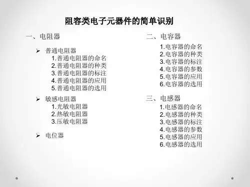
风华SIP直插排阻(排电阻)规格书
- 格式:pdf
- 大小:929.28 KB
- 文档页数:4
sip电阻
SIP电阻是一种表面贴装封装(SMD)电阻,其封装形状为一
个矩形的外壳,具有两个平行的引线,方便焊接到电路板上。
SIP电阻的封装和尺寸通常符合国际标准,可以很方便地与其
他SMD元件配合使用。
在电路设计中,SIP电阻常用于限流、阻抗匹配、电平转换等功能。
SIP电阻通常由金属薄膜或金属氧化物膜组成,具有较高的精
度和稳定性。
其阻值范围广泛,可以根据需要选择,常见的阻值范围包括从几欧姆到几兆欧姆。
SIP电阻具有很好的电气性能,包括低温漂移、低噪音和低电
感等特点。
此外,其封装材料通常具有良好的耐高温性能,适用于各种工作环境。
总之,SIP电阻是一种常用的电阻元件,广泛应用于各种电子
设备和电路中。
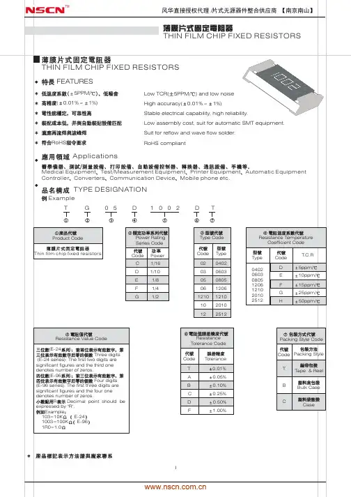
广东风华高新科技股份有限公司GUANGDONG FENGHUA ADV ANCED TECHNOLOGY HOLDING CO.,LTD.承认书APPROV AL SHEET客户名称:CUSTOMER品名:常规厚膜片式固定电阻器PARTNAME规格版本号VERSION日期DATE制造客户APPROV AL APPROV AL 拟制审核确认检验审核批准FENGHUAFENG HUA ADV ANCED TECHNOLOGY (HOLDING) CO., LTD序号 No 目 录TABLE OF CONTENTS1.0 概述Summary2.0 结构及尺寸Structure And Dimensions3.0 型号规格表示办法How To Order4.0 电气性能Performance Specification5.0 可靠性Reliability Data6.0 包装Package7.0 环保情况说明 Environmental Protection Statement 8.0 推荐使用的焊接曲线Recommended soldering profile 9.0 使用注意事项Precautions For UseRC/RS□□□□1.0概述Summary片式电阻器主要生产的型号包括01005、0201、0402、0603、0805、1206、1210、2010、2512。
其特点是:The dimension type for chip resistor including01005、 0201、0402、0603、0805、1206、1210、2010、2512, and the features are as below:*体积小、重量轻miniature and light weight*电性能稳定,可靠性高 stable electrical capability and high reliability *机械强度高、高频特性优越superior mechanical and frequency*装配成本低,并与自动贴装设备匹配low assembly cost, suit for automatic SMT *适应再流焊与波峰焊suit for re-flow and wave flow soldering .*符合ROHS指令要求Compliant with ROHS Directive*符合无卤素要求Compliant with halogen free requirement*禁止使用SS-00259中规定的1级环境管理物质*SONY指定原材料只能从绿色伙伴认定供应商处采购产品广泛应用于计算机、通讯、工业自动化、航天航空、军事、数字电视、数字音响及消费类电子等领域。
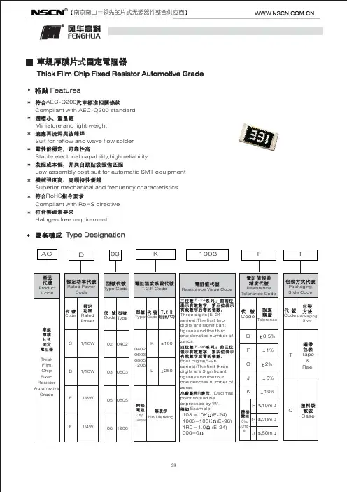
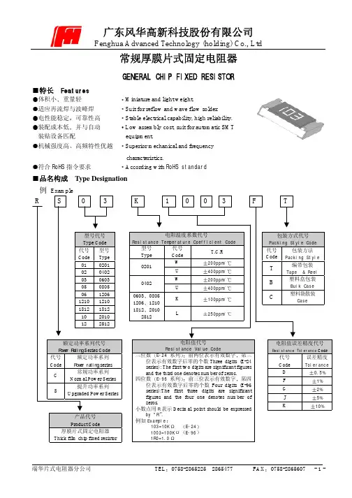
常规厚膜片式固定电阻器GENERAL CHIP FIXED RESISTOR特长 Features体积小重量轻Miniature and light weight.适应再流焊与波峰焊Suit for reflow and wave flow solder.电性能稳定可靠性高Stable electrical capability, high reliability.装配成本低并与自动Low assembly cost, suit for automatic SMT装贴设备匹配equipment.机械强度高高频特性优越Superior mechanical and frequencycharacteristics.符合RoHS指令要求According with RoHS standard品名构成 Type Designation例Example200ppm/400ppm/200ppm/400ppm/100ppm/0603080512061210181220102512250ppm/Resistance Value Code三位数E-24系列前两位表示有效数字第三位表示有效数字后零的个数Three digits (E-24series): The first two digits are significant figuresand the third one denotes number of zeros.四位数E-96系列前三位表示有效数字第四位表示有效数字后零的个数Four digits (E-96series):The first three digits are significantExample103=10K E-241003=100K E-961R0=1.00.5%1%2%5%10%结构及规格尺寸Construction and dimension单位Unit: mm 型号Type L W t a b 0201 0.600.05 0.300.05 0.230.05 0.100.05 0.150.05 0402 1.000.10 0.500.10 0.300.10 0.200.10 0.250.10 0603 1.600.15 0.800.15 0.400.10 0.300.20 0.300.20 0805 2.000.20 1.250.15 0.500.10 0.400.20 0.400.20 1206 3.200.20 1.600.15 0.550.10 0.500.20 0.500.20 1210 3.200.20 2.500.20 0.550.10 0.500.20 0.500.20 1812 4.500.20 3.200.20 0.550.10 0.500.20 0.500.20 2010 5.000.20 2.500.20 0.550.10 0.600.20 0.600.20 2512 6.400.20 3.200.20 0.550.10 0.600.20 0.600.20产品外观Appearance1.电阻器表面二次玻璃体保护膜覆盖完好且难以脱落,表面平整The surface of resistor is covered with Protective Coating which hard to fade, and the surface of coating should avoid unevenness.2.电阻器引出端电极覆盖均匀镀层较难脱落且平整无裂痕针孔变色The terminal part is covered equable , the plating is hard to fade, and should avoid unevenness, flaw, pinhole and discoloration.3.电阻器芯片无裂痕标志可辨With a clear mark , the resistor body is crack-free.参考标准 Reference StandardGB/T 5729-2003GB/T 9546-1995JIS C 5223-1995JIS C 5201-1998JIS C 5202-1990负荷下降曲线Derating Curve755025使用温度范围OperatingTemperatureRange-55125环境温度Ambient temperature ()当电阻使用的环境温度超过70时其额定负荷(额定电压)按上述曲线下降For resistors operated in ambient over 70,rated load (power rating) shall be derated in accordance with the above figure.额定值 Ratings项目 Item 0201 0402 06030805 1206 1210 1812 20102512常规功率系列Normal PowerSeries1/20W 1/16W1/16W1/10W1/8W 1/4W 1/2W 1/2W1W 额定功率Power Rating提升功率系列Upgraded PowerSeries/ /1/10W1/8W1/4W1/3W/ 3/4W/最大工作电压VMax.Working Voltage25 50 50 150200 200 200 200 200最大过负荷电压VMax.Overload Voltage50 100 100 300400 400 400 400 400电阻温度系数Resistance TemperatureCoefficient10R 1M:200ppm/1R<10,1M<R10M:400ppm/10R1M:100ppm/1R<10,1M<R10M:250ppm/阻值范围Resistance Range1~10ME-24E-96系列阻值误差精度Resistance Tolerance5%10%1~10M: 1%2%5%10%10~1M:0.5%1~10M: 1%2%5%10%10~1M:0.5%1% 2% 5%10% 使用温度范围Operating Temperature Range-55~+125额定温度Rated Temperature70注额定电压=额定功率标称电阻值或最大工作电压两者中的较小值Note Rated Voltage=Power Rating Resistance Value or Max. Working Voltage , whichever is lower.特性 Characteristics项目Item标准Specifications测试方法JIS C 5202标准Test Methods (JIS C 5202)端头强度Bending Strength无可见损伤No mechanical damageR 1.0%R+0.05弯曲速度(Speed):1mm/s弯曲距离(Bending Distance):0201040206030805120612103mm1812201025121mm电阻温度系数T.C.R在规定值内within specified T.C.R测定范围-55~+125Measure between -55~+125温度循环TemperatureCycling无可见损伤No mechanical damageR 1.0%R+0.05-5530分钟~常温5分钟~12530分钟5个循环-5530min~normal temperature5min~12530min 5 cycles短时间过负载Short TimeOverload无可见损伤No mechanical damageR 2.0%R+0.052.5倍额定电压或最大过负荷电压取最小者保持5秒2.5Rated voltage or Max. Overload Voltagewhichever is lower for 5 seconds续上表稳态湿热Steady state humidity无可见损伤No mechanical damage R 3.0%R+0.1 40290~95RH 1000小时 402 90~95RH 1000h70耐久性 Load Life无可见损伤No mechanical damageR 3.0%R+0.17021000小时额定电压通1.5小时/断0.5小时7021000hRated voltage 1.5h on/0.5h off上限类别温度耐久性 Endurance atupper temperature 无可见损伤No mechanical damageR 3.0%R+0.11252 1000h 耐溶剂性Resistance toSolvent无可见损伤 No mechanical damage R 1.0%R+0.05 浸入三氯乙烯 10h 1hDip in chloroethylene for 10h 1h .绝缘电阻Insulation Resistance1000M Min在电极与基片间施加100V 直流电压,保持1分钟,然后测绝缘电阻值.Apply DC 100V between substrate and terminationfor 1 minute, then check insulation resistance .耐焊接热 Resistance toSoldering Heat无可见损伤No mechanical damageR 1.0%R+0.052605 10s 1s 可焊性Solderability 可焊面积95% 95% Cover Min2355 2s 0.5s 附着力Adhesion 外观无可见损伤 No mechanical damage 施加力5N 10s 1s Applying 5N 10s 1s包装 Packaging编带包装 Tape and reel * 纸带编带 Paper taping 020104020603080512061210单位unit: mm 型号Type A B W F E 0201 0.700.1 0.400.1 8.00.20 3.50.05 1.750.10402 1.200.1 0.700.1 8.00.20 3.50.05 1.750.10603 1.850.1 1.100.1 8.00.20 3.50.05 1.750.10805 2.350.1 1.650.1 8.00.20 3.50.05 1.750.11206 3.500.2 1.900.2 8.00.20 3.50.05 1.750.11210 3.500.2 2.800.2 8.00.20 3.50.05 1.750.1单位unit: mm 型号Type P P0 P1 ФD0 T 0201 2.00.05 4.00.1 2.00.05 1.50.1 0.5Max0402 2.00.05 4.00.1 2.00.05 1.50.1 0.6Max0603 4.00.1 4.00.1 2.00.05 1.50.1 0.600.10805 4.00.1 4.00.1 2.00.05 1.50.1 0.750.11206 4.00.1 4.00.1 2.00.05 1.50.1 0.750.11210 4.00.1 4.00.1 2.00.05 1.50.1 0.750.1*塑料带编带 Embossed taping单位unit: mm型号Type A0 B0WFEt 1812 4.800.10 3.400.10 12.000.10 5.500.10 1.750.10 0.250.05 2010 5.450.10 2.770.10 12.000.10 5.500.10 1.750.10 0.240.05 25126.730.10 3.400.10 12.000.10 5.500.10 1.750.10 0.240.05单位unit: mm型号Type PP0P1 ФD0ФD1K0 1812 4.000.10 4.000.10 2.000.05 1.550.10 1.500.10 1.000.10 2010 4.000.10 4.000.10 2.000.05 1.50+0.10/-0 1.500.10 0.840.10 25124.000.10 4.000.10 2.000.051.50+0.10/-0 1.500.100.810.10* 卷盘 Reel单位unit: mm型号Type MWTABCD0201 0402 0603 0805 1206 1210 178 2.09.5 1.012.5 1.52.0 0.513.0 0.521.0 0.558.0 2.01812 2010 2512178 2.013.0 0.515.5 1.52.0 0.513.0 0.521.0 0.557.0 2.0*塑料盒包装Bulk case单位unit:mm包装数量 Packaging quantity包装方法Packagingstyle编带Tape and reel塑料盒Bulk case塑料袋散装Bulk型号Type 020104020603080512061210181220102512020104020603 0805 12061210201018122512020104020603080512061210181220102512数量PCSQuantity10000 5000 4000 50000 25000 10000 5000 1500 1000 50000 10000 4000。
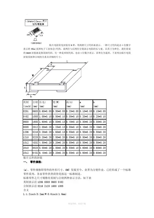
贴片电阻常见封装有9种,用两种尺寸代码来表示。
一种尺寸代码是由4位数字表示的EIA(美国电子工业协会)代码,前两位与后两位分别表示电阻的长与宽,以英寸为单位。
我们常说的0603封装就是指英制代码。
另一种是米制代码,也由4位数字表示,其单位为毫米。
下表列出贴片电阻封装英制和公制的关系及详细的尺寸:贴片元件的封装一、零件规格:(a)、零件规格即零件的外形尺寸,SMT发展至今,业界为方便作业,已经形成了一个标准零件系列,各家零件供货商皆是按这一标准制造。
标准零件之尺寸规格有英制与公制两种表示方法,如下表英制表示法1206 0805 0603 0402公制表示法3216 2125 1608 1005含义L:1.2inch(3.2mm)W:0.6inch(1.6mm)L:0.8inch(2.0mm)W:0.5inch(1.25mm)L:0.6inch(1.6mm)W:0.3inch(0.8mm)L:0.4inch(1.0mm)W:0.2inch(0.5mm)注:a、L(Length):长度; W(Width):宽度; inch:英寸b、1inch=25.4mm(b)、在(1)中未提及零件的厚度,在这一点上因零件不同而有所差异,在生产时应以实际量测为准。
(c)、以上所讲的主要是针对电子产品中用量最大的电阻(排阻)和电容(排容),其它如电感、二极管、晶体管等等因用量较小,且形状也多种多样,在此不作讨论。
(d)、SMT发展至今,随着电子产品集成度的不断提高,标准零件逐步向微型化发展,如今最小的标准零件已经到了0201。
二、常用元件封装1)电阻:最为常见的有0805、0603两类,不同的是,它可以以排阻的身份出现,四位、八位都有,具体封装样式可参照MD16仿真版,也可以到设计所内部PCB库查询。
注:ABCD四类型的封装形式则为其具体尺寸,标注形式为L X S X H1210具体尺寸与电解电容B类3528类型相同0805具体尺寸:2.0 X 1.25 X 0.5(公制表示法)1206具体尺寸:3.0 X 1.5 0X 0.5(公制表示法)2)电阻的命名方法1、5%精度的命名: RS – 05 K 102 JT2、1%精度的命名:RS – 05 K 1002 FTR -表示电阻S -表示功率0402是1/16W、0603是1/10W、0805是1/8W、1206是1/4W、1210是1/3W、1812是1/2W、2010是3/4W、2512是1W。
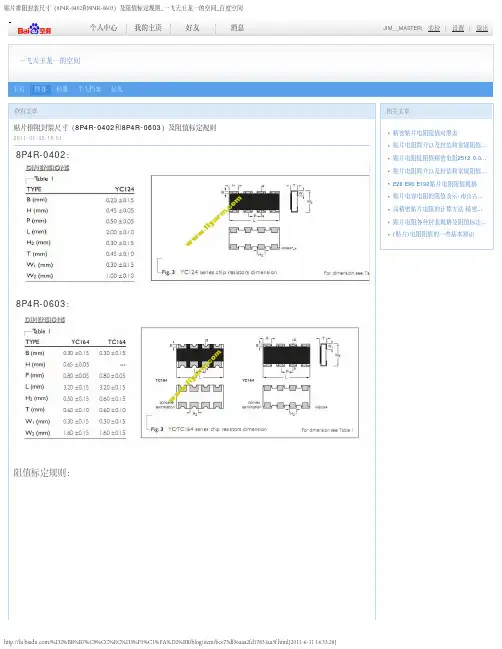
8P4R-0402: 8P4R-0603:阻值标定规则:精密贴片电阻阻值对照表贴片电阻简介以及封装和常规阻值贴片电阻低阻值精密电阻贴片电阻简介以及封装和常规阻值E26 E96 E192贴片电容电阻的阻值表示高精密贴片电阻的计算方法贴片电阻各种封装规格及阻值标注(A型排阻的引脚总是奇数的。
它的左端有一个公共端(用白色的圆点表示),常见的排阻有4、7、8个电阻,所以引脚共有5或8或9个。
B型排阻的引脚总是偶数的。
它没有公共端,常见的排阻有4个电阻,所以引脚共有8个。
排阻的阻值读法如下:“103”表示:10kΩ,“510”表示:51Ω。
以此类推。
选用时要注意,有的排阻内有两种阻值的电阻,在其表面会标注这两种电阻值,如220Ω/330Ω,所以SIP排阻在应用时有方向性,使用时要小心。
SMD排阻安装体积小,目前已在多数场合中取代了SIP排阻。
常用的SMD排阻有8P4R(8引脚4电阻)和10P8R(10引脚8电阻)两种规格。
其电路原理图符号如图所示。
排阻的阻值通常用三位数字表示,标注在电阻体表面。
在三位数字中,从左至右的第一、第二位为有效数字,第三位表示前两位数字乘10的N次方(单位为Ω)。
如果阻值中有小数点,则用“R”表示,并占一位有效数字。
例如:标示为“103”的阻值为10×10=10kΩ,标示为“222”的阻值为2200Ω即2.2kΩ,标示为“105”的阻值为1MΩ。
需要注意的是,要将这种标示法与一般的数字表示方法区别开来,如标示为220的电阻器阻值为22Ω,只有标志为221的电阻器阻值才为220Ω。
| | lucy__rose没有。
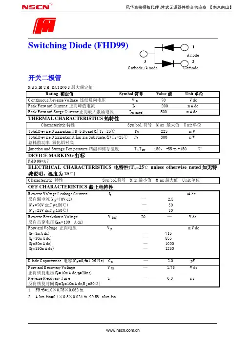
Switching Diode (FHD99)12开关二极管 MAXIMUM RATINGS 最大额定值Rating 额定值 Symbol 符号 Value 值 Unit 单位 Continuous Reverse V oltage 连续反向电压 V R 70 Vdc Peak Forward Current 正向峰值电流 I F 200 mAdc Peak Forward Surge Current 正向最大浪涌电流 I FM(surge) 500 mAdc THERMAL CHARACTERISTICS 热特性Characteristic 特性 Symbol 符号 Max 最大值 Unit 单位 Total Device Dissipation FR-5 Board(1) T A =25℃ P D 225 mW Total Device Dissipation Alumina Substrate,(2) T A =25℃ P D 300 mW 总耗散功率 氧化铝衬底Junction and Storage Temperature 结温和储存温度 T J ,T stg 150, -55 to +150 ℃ DEVICE MARKING 打标FHD99=A7ELECTRICAL CHARACTERISTICS 电特性(T A =25℃ unless otherwise noted 如无特殊说明,温度为25℃)Characteristic 特性 Symbol 符号 Min 最小值 Max 最大值 Unit 单位 OFF CHARACTERISTICS 截止电特性Reverse V oltage Leakage Current I R μAdc 反向漏电流(V R =70Vdc) —2.5(V R =70Vdc,T j =150℃) — 50(V R =25Vdc,T j =150℃) — 30Reverse Breakdown V oltage V (BR) 70 — Vdc 反向击穿电压(I BR =100μAdc)Forward V oltage 正向电压 V F mVdc (I F =1mAdc) — 715(I F =10mAdc) —855 (I F =50mAdc) —1000 (I F =150mAdc) —1250 Diode Capacitance 电容(V R =0,f=1.0MHz) C D — 2.0 pF Forward Recovery V oltage V FR — 1.75 Vdc 正向恢复电压(I F =10mAdc,t r =20ns)Reverse Recovery Time t rr — 6.0 ns 反向恢复时间(I F =I R =10mAdc,R L =50Ω)1. FR-5=1.0×0.75×0.062 in.2. Alumina=0.4×0.3×0.024 in. 99.5% alumina. 风华直接授权代理/片式无源器件整合供应商 【南京南山】。

贴片电阻规格贴片电阻常见封装有9种,用两种尺寸代码来表示。
一种尺寸代码是由4位数字表示的EIA(美国电子工业协会)代码,前两位与后两位分别表示电阻的长与宽,以英寸为单位。
我们常说的0603封装就是指英制代码。
另一种是米制代码,也由4位数字表示,其单位为毫米。
下表列出贴片电阻封装英制和公制的关系及详细的尺寸:英制(inch) 公制(mm)长(L)(mm)宽(W)(mm)高(t)(mm)a(mm)b(mm)0201 0603 0.60±0.05 0.30±0.05 0.23±0.05 0.10±0.05 0.15±0.050402 1005 1.00±0.10 0.50±0.10 0.30±0.10 0.20±0.10 0.25±0.100603 1608 1.60±0.15 0.80±0.15 0.40±0.10 0.30±0.20 0.30±0.200805 2012 2.00±0.20 1.25±0.15 0.50±0.10 0.40±0.20 0.40±0.201206 3216 3.20±0.20 1.60±0.15 0.55±0.10 0.50±0.20 0.50±0.201210 3225 3.20±0.20 2.50±0.20 0.55±0.10 0.50±0.20 0.50±0.201812 4832 4.50±0.20 3.20±0.20 0.55±0.10 0.50±0.20 0.50±0.202010 5025 5.00±0.20 2.50±0.20 0.55±0.10 0.60±0.20 0.60±0.202512 6432 6.40±0.20 3.20±0.20 0.55±0.10 0.60±0.20 0.60±0.20一、零件规格:(a)、零件规格即零件的外形尺寸,SMT发展至今,业界为方便作业,已经形成了一个标准零件系列,各家零件供货商皆是按这一标准制造。
Approval SheetforThick Film Chip ResistorRL series1% 2% 5%YAGEO CORPORATIONFactory: No.11, Min Chuan Rd., Ta Sheh, Kaohsiung, Taiwan, R.O.C.Tel: 886-7-351-4117 Fax: 886-7-352-6475Headquarters: 3F, No.233-1, Pao Chiao Rd., Hsin Tien, Taipei, Taiwan,R.O.C.Tel: 886-2-2917-7555 Fax: 886-2-2917-4286RL Series Version 2000-3 Page-1RL SeriesVersion 2000-3 Page-21. SUBJECT : This specification describes of RL series chip resistors made of YAGEOCorporation by thick film process.2. PART NUMBER : Part number of the chip resistor is identified by the series, size,tolerance, packing style, temperature coefficient, special type and resistance value.Example :RL 1206 F R - 07 0R02Series Size Resistance Packing Temperature Special ResistanceName Code Tolerance Style Coefficient Type Valueof Resistance(1) Size : (unit: inches)0603=0.063×0.033 1210=0.122×0.102 0805=0.083×0.051 2010=0.197×0.098 1206=0.122×0.0632512=0.250×0.126(2) Tolerance : F=±1%, G=±2%, J=±5%(3) Packaging Style : R =Paper Taping Reel. K =Embossed Plastic Tape Reel. C =Bulk Cassette.(4) T .C .R.: “-“Base on Spec.(5) Special Type : 07= 7 inch Dia. Reel10=10 inch Dia. Reel 13=13 inch Dia. Reel(6) Resistance Value : 10m Ω、20 m Ω、51 m Ω、100 m Ω、330 m Ω、470 m Ω……(7) Resistance Series : E24 (E48/96 on request)RL SeriesVersion 2000-3 Page-33. MARKING :(1) RL0805/RL1206/RL1210/RL2010/RL2512Either tolerance in 5% or 1%: 4 digits, uses MIL Standard resistance marking. “R” signifies decimal place.Value =20m Ω(2) RL0603Tolerance in 5%: 3 digits, uses MIL Standard resistance marking. “R” signifies decimal place.Value =220m Ω1% Tolerance : no marking4. POWER RATING(1) Rated Power at 70°C :RL0603=1/10WRL1210=1/3W RL0805=1/8W RL2012=3/4W RL1206=1/4WRL2512=1W(2) Rated Voltage : The DC or AC (rms) continuous working voltage correspondingto the rated power is determined by the following formula : V= √(P X R)Where V= Continuous rated DC or AC (rms) working voltage (V)P= Rated power (W) R= Resistance value (Ω)5. ELECTRICAL CHARACTERISTICSSTYLE RL0603 RL0805 RL1206 Operating Temp. Range -55°C ~ +125°CDerated to 0 Load at +125°CResistance Range 100mΩ≦Rn<1Ω 20mΩ≦Rn<1Ω 10mΩ≦Rn<1ΩTemperature Coefficient ±600ppm/°C±1500ppm/°CSTYLE RL1210 RL2010 RL2512 Operating Temp. Range -55°C ~ +125°CDerated to 0 Load at +125°CResistance Range 10mΩ≦Rn<1Ω 10mΩ≦Rn<1Ω 10mΩ≦Rn<1ΩTemperature Coefficient ±1500ppm/°CRL Series Version 2000-3 Page-4RL SeriesVersion 2000-3 Page-58. ENVIRONMENTAL CHARACTERISTICS(1) Temperature Coefficient of Resistance (T.C.R.)Test Method : Measure resistance at +25°C or specified room temperature asR 1, then measure at -55°C or +125°C respectively as R 2. Determine the temperature coefficient of resistance from the following formula.R 2-R 1 `T.C.R.= ----------------- X 106(PPM/°C) R 1 (t 2-t 1)Where t 1 =+25°C or specified room temperaturet 2 = -55°C or +125°C test temperatureR 1=resistance at reference temperature in ohms. R 2=resistance at test temperature in ohms.Acceptance Standard : (Refer to item 5)(2) Thermal ShockTest Method : -55±3°C, 2 minutes and +125±2°C, 2 minutes as one cycle. After5 cycles, the specimen shall be stabilized at room temperature for 1 hour minimum and then measure the resistance to determine △R/R(%).Acceptance Standard : ±1.0%(3) Low Temperature OperationTest Method : Place the specimen in a test chamber maintained at -65 °C. After one hour stabilization at this temperature, full rated workingvoltage shall be applied 45 minutes. Have15 minutes after remove the voltage, the specimen shall be removed from the chamber and stabilized at room temperature for 24 hrs. Measure the resistance to determine △R/R(%).Acceptance Standard : ±1.0%No mechanical damage.+5+5 -0 +0+0-5+5+5-0RL SeriesVersion 2000-3 Page-6(4) Short Time OverloadTest Method : Apply 2.5 times of rated voltage but not exceeding the maximumoverload voltage for 5 seconds. Have the specimen stabilized at room temperature for 30 minutes minimum. Measure the resistance to determine △R/R(%).Acceptance Standard : ± 1.0% for 1% tolerance± 2.0% for 2~5% toleranceNo evidence of mechanical damage(5) Insulation ResistanceTest Method : Place the specimen in the jig and apply a rated continuesoverload voltage (R.C.O.V) for one minute as shown. Measure the insulation resistance.Type Voltage Type Voltage RL0603 100V RL1210 400V RL0805 300V RL2010 400V RL1206 400V RL2512 400VAcceptance Standard : ≧10000M Ω(6) Dielectric Withstand VoltageTest Method : Place the specimen in the jig and apply a specified valuecontinuous overload voltage as shown for one minute.Type Voltage TypeVoltage RL0603 100V RL1210 400V RL0805 300V RL2010 400V RL1206 400V RL2512 400VAcceptance Standard : Breakdown voltage>specification and without open/short(7) Resistance to Soldering HeatTest Method: Immerse the specimen in the solder pot at 260±5°C for 10±1seconds. Have the specimen stabilized at room temperature for30 minutes minimum.Measure the resistance to determine △R/R(%).Acceptance Standard:±1.0% & no visible damage(8) Moisture ResistanceTest Method: Place the specimen in the test chamber, and subjected to 42damp heat cycles. Each one of which consists of the steps 1 to 7as figure 1. The total length of test is 1000 hours. After the test,have the specimen stabilized at room temperature for 24 hoursand measure the resistance to determine △R/R(%).Acceptance Standard:±2.0% & no visible damageFig.1 Conditions of change of temperatureRL Series Version 2000-3 Page-7RL SeriesVersion 2000-3 Page-8(9) LifeTest Method : Place the specimen in the oven at 70±2°C. Apply the rated voltageto the specimen at the 1.5 hours on and 0.5 hour off cycle. The total length of test is 1000 hours. After the test, have the specimen stabilized at room temperature for one hour minimum and measure the △R/R(%).Acceptance Standard : ± 2.0% for 1% tolerance± 3.0% for 2~5% tolerance(10) SolderabilityTest Method : Immerse the specimen in the solder pot at 230±5°C for 5 sec.Acceptance Standard : At least 95% solder coverage on the termination.9. TAPING REELUnit :mmStyle Packaging Tape width ∅A ∅B ∅C W TRL0603 RL0805 RL1206 RL1210Paper 8mm 180+0-360+1-0 13.0±0.29.0±0.3 11.4±1RL2010 RL2512Embossed 12mm 180+0-360+1-0 13.0±0.213.0±0.3 15.4±1RL SeriesVersion 2000-3 Page-910. PAPER TAPINGUnit : mmDimensionA B W E F P0 P1 P2 ΦD0 TRL0603 1.10±0.1 1.90±0.1 0.70±0.10RL0805 1.65±0.1 2.40±0.1 0.85±0.10RL1206 1.90±0.1 3.50±0.1 0.85±0.10RL12102.80±0.13.50±0.18.0±0.2 1.75±0.13.5±0.054.0±0.14.0±0.052.0±0.051.5+0.1 -00.85±0.1011. EMBOSSED TAPINGDimensionA B W E F P0P1P2ΦD0ΦD1TRL2010 2.8±0.2 5.4±0.2RL2512 3.5±0.2 6.7±0.212.0±0.3 1.75±0.15.5±0.054.0±0.14.0±0.12.0±0.05 1.5±0.1 1.5±0.25 1.0±0.112. PACKING METHODSPAPERRL Series Version 2000-3 Page-10。
常用元器件介绍编写人:熊帮新审核人:龙从玉任何电子电路都是由元器件组成的。
而常用的主要是电阻器、电容器、电感器和各种半导体(如二极管、三极管、场效应管、集成电路等)为了正确地选择和使用这些元、器件,就必须对它们的各种性能、结构与规格有一个完整的了解。
一、电阻器和电位器1.1、电阻器R图1.1电阻器的外形和符号在电子设备中,电阻器是应用最广泛的一种元件。
其主要用途是稳定和调节电路中电流和电压。
其次还可作为分流器、分压器和消耗能量的负载等。
常用电阻器有实心碳质电阻、薄膜电阻器、线绕电阻器和热敏电阻器等,其中又有固定电阻器和可变电阻器之分。
常用电阻器的外形和符号如图1.1所示。
1.2、电位器W图1.2输出特性和函数关系图1.3电位器的外形和符号电位器是一种具有三个接头的可变电阻器。
其阻值可在一定范围内连续可调。
电位器的种类有以下几种:电阻按照材料可分为:碳质、薄膜和线绕三种。
它们的性能和特点与同质材料的固定电阻器相似,所不同的只是电位器有可动的触点。
因而使用电位器时需要考虑它的阻值变化特性、接触的可靠性、材料的耐磨性等等。
一般而言,线绕电位器的误差小于±10%,非线性电位器的误差小于±20%。
其阻值、误差和型号均标在电位器上。
按调节机构的运动方式可分为:旋转式、直滑式。
按机构可分为单联、双联、带开关、不带开关等;开关式又分为旋转式、推拉式、按键等。
按用途可分为普通电位器、精密电位器、功率电位器、微调电位器和专业电位器等。
按输出特性和函数关系可分为线性和非线性电位器,如图6.1.2所示。
线绕电位器的阻值变化特性一般都是直线式的。
非线性电位器的阻值变化特性分为直线式(X 型)、对数式(D 型)、指数式(Z 型)三种。
所有X 、D 、Z 字母符号一般印在电位器上,使用时应主意。
常用电位器的外形和符号如图1.3所示。
1.3、电阻器和电位器的命名法电阻器和电位器的命名如表1.1所示。
表1电阻器型号命名方法第一部分:主称第二部分:材料第三部分:特征分类意义符号意义符号意义符号电阻器电位器第四部分:序号R 电阻器T 碳膜1普通普通W电位器H 合成膜2普通普通S 有机实芯3超高频――N 无机实芯4高阻――J 金属膜5高温――Y 氧化膜6――――C 沉积膜7精密精密I 玻璃釉膜8高压特殊函数P 硼碳膜9特殊特殊U 硅碳膜G 高功率――X 线绕T 可调――M 压敏W ――微调G 光敏D ――多圈R热敏B 温度补偿用――C 温度测量用――P 旁热式――W 稳压式――Z正温度系数――对主称、材料相同,仅性能指标、尺寸大小有差别,但基本不影响互换使用的产品,给予同一序号;若性能指标、尺寸大小明显影响互换时,则在序号后面用大写字母作为区别代号。