低TCR超低阻值贴片电阻规格书(选型手册)
- 格式:pdf
- 大小:2.11 MB
- 文档页数:9
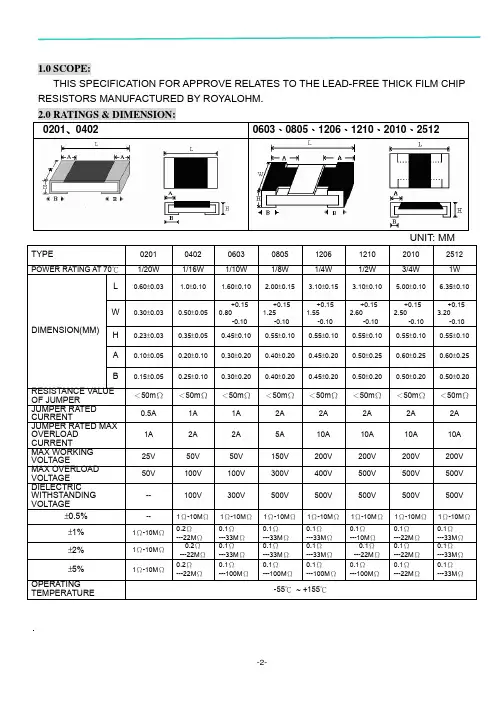
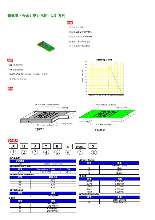
超低阻(合金)贴片电阻-LR 系列-高功率可达3W-低温漂±50, ±100 PPM/℃-阻值从0.5到20 m ohms-低感抗,未经激光切制-可以依据客户要求制作-NB (-MB (--监视器(c产品类型产品类型LR 超低阻合计贴片电阻d Dimensions (L×W)代号Dimensions (L×W) EIALR12 6.3×3.1mm2512e Resistance Tolerance代号阻值公差J ±5%H ±3%G ±2%F ±1%f Packaging代号类别T TapingReelg TCR代号类别D ±50 PPM/℃W ±75 PPM/℃E ±100 PPM/℃K ±150 PPM/℃R003h Power Rating代号类别Standard (1W)S (2W)R (3W)B (2.5W)i阻值代号类别0M50 0.00050Ω0M75 0.00075Ω1M50 0.00150ΩR002 0.00200ΩR020 0.02000Ωj Protective Coating代号类别BlackCoatingG GreenCoatingOperating Current I=√(P/R):Operating Voltage V=√(P*R) 高功率电器特性Operating Current I=√(P/R),Operating Voltage V=√(P*R) * Viking 能够根据客户要求制作一下选项。
凸层塑料带说明Top Tape1 1.4Min.Unit: mm阻值 (m Ω)ABW E F P 0P 1P 2ΦD 0T 0.50 3.40±0.1 6.70±0.112.0±0.1 1.75±0.1 5.5±0.05 4.0±0.05 4.00±0.1 2.0±0.05 1.50+0.1 1.40±0.10.75 3.50±0.1 6.80±0.212.0±0.1 1.75±0.1 5.5±0.05 4.0±0.05 4.00±0.1 2.0±0.05 1.50+0.1 1.35±0.11~203.40±0.1 6.70±0.112.0±0.1 1.75±0.15.5±0.054.0±0.054.00±0.12.0±0.05 1.50+0.10.80±0.1注意:1. 10个齿轮的倾斜积累公差是 ±0.2mm.2. 通过250mm 的凸形带时,每100mm 不高出1mm3. A 和 B 测量是从带底端0.3mm 处开始测量4. t 尺寸的测量是从凸形带的顶端到底端某一点的测量距离。
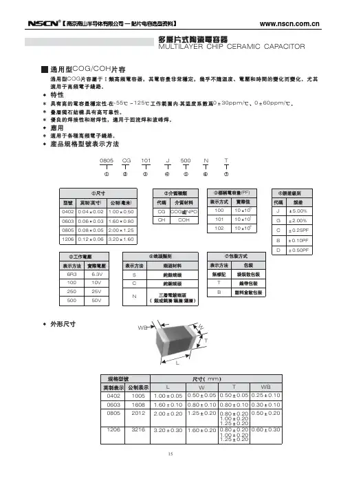
【 南京南山半导体有限公司 — 贴片电容选型资料】MULTILAYER CHIP CERAMIC CAPACITORCOG/COHCOG, ,-55125,030ppm/060ppm/0805CG101J500NT(PF) ( 0402 0.04 0603 0.06 0805 0.08 1206 0.12 ) 0.02 0.03 0.05 0.06 1.00 1.60 2.00 3.20 ( ) 0.50 0.80 1.25 1.60 CG CH COG NPO COH 100 101 102 10 100 1J G C B D5.00% 2.00% 0.25PF 0.10PF 0.50PF10 10 10 1026R3 100 250 5006.3V 10V 25V 50VS C N / / T BWBWTL mm L 0402 0603 0805 1206 1005 1608 2012 3216 1.00 1.60 2.00 3.20 0.05 0.10 0.20 0.30 W 0.50 0.80 1.25 1.60 0.05 0.50 0.10 0.80 0.20 0.80 1.00 1.25 0.20 0.80 1.00 1.25 T WB 0.05 0.25 0.10 0.30 0.20 0.50 0.20 0.20 0.20 0.60 0.20 0.20 0.10 0.10 0.20 0.3015【 南京南山半导体有限公司 — 贴片电容选型资料】0.80 0.20 1.00 0.20 0.50 0.80 0.20 1.00 0.20 0.600.20 0.30【 南京南山半导体有限公司 — 贴片电容选型资料】MULTILAYER CHIP CERAMIC CAPACITORCOG/COH 0402 0603 0805 12066.3V 10V 16V 25V 50V 6.3V 10V 16V 25V 50V 6.3V 10V 16V 25V 50V 6.3V 10V 16V 25V 50V0.5PF 1PF 2PF 3PF 4PF 5PF 6PF 7PF 10PF 22PF 33PF 47PF 68PF 100PF 120PF 150PF 180PF 220PF 330PF 470PF 560PF 680PF 1000PF 2200PF 2700PF 3300PF 4700PF 5600PF 6800PF 10nF 12nF 15nF 22nF 47nF 68nF 100nF17【 南京南山半导体有限公司 — 贴片电容选型资料】04020603080512066.3V 10V 16V 25V 50V 6.3V 10V 16V 25V 50V 6.3V 10V 16V 25V 50V 6.3V 10V 16V 25V 50VCapacitance0.5PF 1PF 2PF 3PF 4PF 5PF 6PF 7PF 10PF 22PF 33PF 47PF 68PF 100PF 120PF 150PF 180PF 220PF 330PF 470PF 560PF 680PF 1000PF 2200PF 2700PF 3300PF 4700PF 5600PF 6800PF 10nF 12nF 15nF 22nF 47nF 68nF 100nF【 南京南山半导体有限公司 — 贴片电容选型资料】MULTILAYER CHIP CERAMIC CAPACITORCOG COHPH~SLCOG PH SH SL TH RH UJCOH1-55125-55851. 2. 3. 2 4. 5. , , , , , 103 4 Cr 5PF 0.56% -4 5PF Cr 50PF 1.5 [(150/Cr)+7] 10 Cr 50PF 0.15% C C 10nF Ri 10nF Ri 5 10 Cr 500s 3 50mA 150+0/-10 8 25 9 75 235 5 2 0.5 25 60 265 10 1 25 : 1 2 100 170 120 200 1 1 2.5mm/ 24 2 5 5 5 2.5mm/ 245 24 -55 125 2 -55 85 60 510:HP4278A 1. 2. 3. (D.F.) :1.0 C : : (HP4284 25 5 0.2V 0.1MHz; 0.1KHZ ) 1000PF,1.0 :SF2511 , 60 60 1 5 :30% 75%5:C<1000PF,1.06I.R.7>3x150+0/-10 5% 0.5PF D.F. 10 I.R. 24 245【 南京南山半导体有限公司 — 贴片电容选型资料】General COGCOHPHSL MLCC reliability test methodStandard Number Item COG COH MLCC for General-use -55 125 PH, RH, SH, TH, UJ, SL MLCC for General-use -55 85 Check by using microscope 10 . Test Method1Operating Temperature RangeAppearance21.Good ceramic body color continuity. 2.The chips have no visual damages and must be very smooth. 3.No exposed inner- electrode, no cracks or holes. 4.The outer electrode should have no cracks, holes, damages or surface oxidation. 5.Outer electrode no prolongation or the prolongation is less than half of that of the termination width.3 4 5Dimensions Capacitance Dissipation Factor (DF)Within the specified dimensions Within the specified tolerance Cr 5PF 0.56% 5PF Cr 50PF 1.5 [(150/Cr)+7] 10-4 Cr 50PF 0.15% C C 10nF Ri 10nF Ri 5 1010 Cr 500sUsing micrometer or vernier calipers Measuring Equipments:HP4278 capacitance meter,HP4284 capacitance, Measuring Conditions: 1.Measuring Temperature:25 5 .Humidity: 30% 75%. 2.Measuring Voltage:1.0 0.2V. 3.Measuring Frequency:C<1000PF 1.0 0.1MHz C 1000PF 1.0 0.1KHz Measuring Equipment:Insulation resistance meter (such as Sf2511 insulation resistance). Measuring Method:Must measure at rated voltage, and measure the IR within 60 5 seconds. Must measure at 3 times rated voltage, dwell time: 60 1 seconds, no short and the changing/discharging current less than 50mA. First, pre-heat: heat treat 60 5 minutes at 150+0/-10 , then set it for 24 2 hours at room temperature. Measure the capacitance at -55 125 or -55 85 , the capacitance change ratio comparing to that of 25 must be within the specified range. Dip the capacitor into ethanol or colophony solution, and then dip it into 235 5 ( or 245 5 leadless eutedtic solder solution ) eutectic solder solution hanving lead for 2 0.5 seconds. Dipping speed: 25 2.5mm/second. First pre-heat: heat treat for 60 5 minutes at 150+0/-10 , then set it for 24 2 hours at room temperature. Then pre-heat the capacitance according to the following chart. Dip the capacitor into 265 5 eutectic solder solution for 10 1 seconds. Then set it for 24 2 hours at room temperature, then measure. Dipping speed: 25 2.5mm/second. Preheat conditions: Stage 1 2 Temperature 100 170 120 200 Time 1minute 1minute6Insulation Resistance7Withstanding Voltage Capacitance Temperature Characteristic>3x rated continuous working voltage Must meet the capacitor character temperature coefficient requirements within the operating temperature range. Tin coverage should be 75% of the outer electrode Appearance Cap. Change ratio DF No defects visible 5%or 0.5PF (whichever is larger)89SolderabilityResistance to Soldering10Same as original spec Same as original specIR46【 南京南山半导体有限公司 — 贴片电容选型资料】MULTILAYER CHIP CERAMIC CAPACITOR1 10N11 10N,10 1 :1.0mm/ 11.5mm 10 D.F. 12 55Hz 210 55Hz 10Hz 6 123 420 mm mmmm13mmmmmmmm150+0/-10 14 24 2 24 260 547【 南京南山半导体有限公司 — 贴片电容选型资料】NumberItems Adhesive Strength of TerminationStandard No removal of the terminations or other defect shall occurTest Method Solder the capacitor to the test jig (glass epoxy resin board) shown in Fig.1 using a eutectic solder.Then apply a 10N force inthe direction shown as the arrowhead.The aoldering shall be done either with an iron or using the reflow method and shall be conducted with care so that an iron or using the refow method and shall be conducted with care so that the soldering is uniform and free of defects such as heat shock,etc. 10N,10 1s Speed:1.0mm/s Glss epoxy resinboard11Fig.1 Vibration Resistance Appearance Capacitance No defects or abnormities Within the specified tolerance range Same as original spec12DFSolder the capacitor to the test jig (glass epoxy resin board). The capacitor should be subjected to a simple harmonic motion having a total amplitude of 1.5mm, the frequency being varied uniformly between the approximate limits of 10 and 55Hz, shall be traversed (from 10 Hz to 55 Hz then 10 Hz again) in approximately 1 minute.This motion shall be applied for a period of 2 hours in each 3 mutually perpendicular directions (total is 6 hours).Same i standarFif.2 Bending Resistance No cracks or other defects shall occur Solder the capacitor to the test jig (glass epoxy resin board) shown in Fig.3 using a eutectic solder. Then apply a 10N force in the direction shown as Fig.4. The soldering shall be done either with an iron or using the reflow method and shall be conducted with care so that the soldering is uniform and free of defects such as mm heat shock, etc.mm13mm mm mm14Temperature CycleAppearance No defects or abnormitiesPre-treatment: Heat-treat the capacitor for 60 5minutes at 150+0/-10 , then set it for 24 2 hours at room temperature. Perform five cycles according to the four heat treatments listed in the following table. Set it for 24 2 hours at room temperature, then measure.48mm【 南京南山半导体有限公司 — 贴片电容选型资料】MULTILAYER CHIP CERAMIC CAPACITOR2.5% 0.25PF, 1 10000M 2 3 4 2 3 30 3 2 3 30 3 2 314D.F. I.R.40 290 95 24 2500+24/-05% 0.5PF, 15 ( ) D.F. I.R. 10000M40 2 500+24/-0 5% 0.5PF, 16 D.F. I.R. 10000M90 95 24 22 50mA 5% 0.5PF, 17 D.F. I.R. 10000M1000 12 24 249【 南京南山半导体有限公司 — 贴片电容选型资料】NumberItem Temperature CycleStandard Cap. Change ratio D.F. I.R. 2.5% or 0.25 PF (whichever is larger) Same as original spec More than 10000M Heat-treatment:Test Method14stage temperature 1 lowest opeating temperature 3 2 normal temperature 3 high operating temperature 2 4 normal temperaturetime min. 30 3 2 3 30 3 2 3Humidity Steady StateAppearance Cap. Change ratio D.F. I.R.No defects or abnormities 5% or 0.5 PF (whichever is larger) Same as original spec More than 10000MSet the capacitor for 500+24/-0 hours at the condition of 40 2 and 90-95% humidity. Then remove and set it for 24 2 hours at room temperature, then measure.15Humidity LoadAppearance Cap. Change ratioNo defects or abnormities 5% or 0.5 PF (whichever is larger) Same as original spec More than 10000MApply rated voltage to the capacitor for 500+24/-0 hours at the condition of 40 2 and 90-95% humidity. Remove and set it for 24 2 hours at room temperature, then measure.16D.F. I.R.Life TestAppearance Cap. Change ratioNo defects or abnormities 5% or 0.5 PF (whichever is larger) Same as original spec More than 10000MApply two times rated voltage to the capacitor for 1000 12 hours at the upper temperature limits, the charging current should be less than 50mA. Remove and set it for 24 2 hours at room temperature, then measure.17D.F. I.R.5057-10%-5%0%5%10%COG 50VX7R 50V Z5U 50V Y5V50V010********-100%-80%-60%-40%-20%0%20%40%[Vdc]COG :1MHZ X7R,Z5U,Y5V:1KHZZ5U 50VY5V 50V X7R 50VC0G 50V0123-20%0%+20%+40%+60%^+80%COG PH RH SH TH UHCOG X7R Y5V,Z5U05010010001000010%0%-10%-20%-30%-40%[Hr]X7R20%0%[Vr ms ]COG :1MHZ X7R,Z5U,Y5V:1KHZMULTILAYER CHIP CERAMIC CAPACITOR58-5%0%5%10%-100%-80%-60%-40%-20%0%20%40%Z5U 50VY5V 50V X7R 50VC0G 50V0123-20%0%+20%+40%+60%^+80%COG X7R Y5V,Z5U05010010001000010%0%-10%-20%-30%-40%0%GENEREL-USE MLCC CHARCCTER PROFILESCapacitance change ratio DC Voltage[Vdc]Measuring condition COG :1MHzX7R,Z5U,Y5V:1KHzCOG and PHRH SH TH UH siriestemperature coefficentDC Capacitance-AC VoltageCharactericsCapacitance change_agingTime[Hr]X7R tempreture characteristicsZ5U [Vr ms ]Capacitance change ratioCapacitance change ratio Capacitance change ratio Capacitance change ratio。

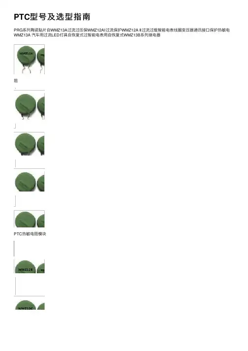
PTC型号及选型指南PRG系列陶瓷贴⽚⾃WMZ13A过流过压保WMZ12AⅠ过流保护WMZ12A Ⅱ过流过载智能电表线圈变压器通讯接⼝保护热敏电WMZ13A 汽车⽤过流LED灯具⾃恢复式过智能电表⽤⾃恢复式WMZ13B系列继电器阻PTC热敏电阻模块电容上电防浪涌冲击⾃恢复热敏电阻逆变焊机滤波电容上电浪涌抑制⾃恢复热敏电阻变频器储能电容浪涌抑制⾃恢复PTC热敏电阻逆变电源滤波电容上电浪涌抑制⾃恢复热敏电阻伺服驱动板滤波电容上电浪涌抑制⾃恢复热敏电阻WMZ12B 140V过流保护PTC热敏电阻WMZ12C 30V/60V 过流保护PTC热敏电阻WMZ12D 15V/18V 过流保护PTC热敏电阻600Vac通讯设备交换机过流过载保护PTC热敏电阻550Vac仪器/仪表/机过流过载保护PTC 热敏电阻250Vac配线架过流过载保护PTC热敏电阻WMZ7消磁PTC热敏电阻WMZ91裸⽚冰箱压缩机启动PTC热敏电阻壳装压缩机启动PTC热敏电阻250Vac配线架过流过载保护⾃恢复PTC热敏电阻通⽤PTC过热保护温度传感器KTY系列电机⽤温度传感器电机PTC热保护温度传感器贴⽚过热保护PTC热敏电阻测温型线性PTC热敏电阻插件过热保护PTC热敏电阻SMD贴⽚线性PTC热敏电阻NXP(恩智浦)KTY系列热敏电阻LED恒流补偿热敏电阻PTC热敏电阻器三⼤特性:BaTiO3陶瓷是⼀种典型的铁电材料,常温下其电阻率⼤于1012Ω.cm,相对介电常数⾼达104,是⼀种优良的陶瓷电容器材料。
在这种材料中引⼊稀⼟元素如Y、Nb等,可使其电阻率下降到10Ω.cm以下,成为具有很⼤的正温度系数的半导体陶瓷材料,在居⾥温度以上⼏⼗度的温度范围内,其电阻率可增⼤4-10个数量级,产⽣PTC效应。
这种效应是⼀种晶界效应,只有多晶陶瓷材料才具有。
正是由于这种PTC效应,PTC热敏电阻器得到了极其⼴泛的应⽤。
根据应⽤领域划分,PTC热敏电阻器有三⼤特性:电阻-温度特性;伏安特性;电流时间特性。
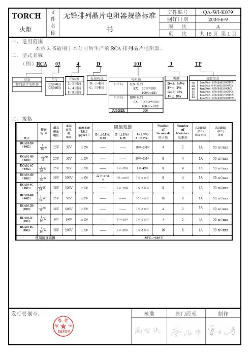
文文件编号QA-WI-K079 件 制订日期 2004-6-9 名 版 次 A TOR C H 火炬 称 无铅排列晶片电阻规格标准 书页 次 共16页 第3页 四、尺寸:( )R C A02-2D/RTA03-2D/RTA03-2C R C A02-4D/RCA03-4DR C A02-4C/RTA03-4CR C A02-8D/RTA03-8CCircuits Circuits2 Circuits L 1 L 1称 页 次 共16页 第7页Specifications 规格 TEM项目Conditions 条件 Resistors Jumper◎测试方法三(电烙铁试验):加热温度:350±10℃电烙铁加热时间:3+1/-0sec.取电铬铁加热于电极两端后,取出静置60分钟以上,再量测阻值变化率。
依据SONY (SS-00254-5)依据JIS-C5202-6.10步骤 制程名称 试验环境条件1 阻值量测 室温2 烘干 125℃、24小时3 湿润 85℃、85%RH 、168小时4 焊锡炉测试260±3℃、10秒 5 静置 室温6 焊锡炉测试260±3℃、10秒 7 阻值量测 室温Solderability 焊锡性 前处理将晶片电阻放置于PCT 试验机内,在温度105℃、湿度100%及气压1.22×10⁵ pa 的饱和条件下进行4小时的老化测试,取出后静置于室温下2小时。
测试方法◎测试项目一(焊锡炉测试):将电阻浸于245±3℃之炉中3+1/-0秒后取出置于显微镜下观察焊锡面积。
◎测试项目二(小球平衡法):将浸渍助焊剂后的电阻置放于Wetting Balance 测试机,依下列条件做设定,并记录晶片电阻焊锡润湿时间。
焊锡槽平衡法测试条件条件焊锡温度 245±3℃浸渍速度 1~5mm/S浸渍高度 0.10mm浸渍角度 水平25mg →0402、0603 锡球重量 200mg →0805、1206、1210、2010、2512依据SONY (SS-00254-2)依据JIS-C5202-6.111.试验项目一: 导体吃锡面积应大于95%。
贴片电阻规格、封装、尺寸ChipR Dimensions 、Footprint简述基本结构分类规格、封装、尺寸额定功率及工作电压阻值,标准阻值标识规格书、生产厂家命名方法价格、报价创建时间:2005-12-30 最后修改时2006我们常说的贴片电阻(SMD Resistor)叫"片式固定电阻器"(Chip Fixed Resistor),又叫"矩形片状电阻"(Rectangular Chip Resistors),是由ROHM公司发明并最早推出市场的。
特点是耐潮湿,耐高温,可靠度高,外观尺寸均匀,精确且温度系数与阻值公差小。
按生产工艺分厚膜(Thick Film Chip Resistors)、薄膜(Thin Film Chip Resistors )两种。
厚膜是采用丝网印刷将电阻性材料淀积在绝缘基体(例如玻璃或氧化铝陶瓷)上,然后烧结形成的。
我们通常所见的多为厚膜片式电阻,精度范围±0.5% ~ 10%,温度系数:±50PPM/℃~ ±400PPM/℃。
薄膜是在真空中采用蒸发和溅射等工艺将电阻性材料淀积在绝缘基体工艺(真空镀膜技术)制成,特点是低温度系数(±5PPM/℃),高精度(±0.01%~±1%)。
封装有:0201,0402,0603,0805,1206,1210,1812,2010,2512。
其常规系列的精度为5%,1%。
阻值范围从0.1欧姆到20M欧姆。
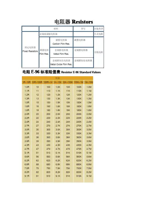
标准阻值有E24,E96系列。
功率有1/20W、1/16W、1/8W、1/10W、1/4W、1/2W、1W。
特性:•体积小,重量轻•适合波峰焊和回流焊•机械强度高,高频特性优越•常用规格价格比传统的引线电阻还便宜•生产成本低,配合自动贴片机,适合现代电子产品规模化生产使用状况:由于价格便宜,生产方便,能大面积减少PCB面积,减少产品外观尺寸,现在已取代绝大部分传统引线电阻。

贴片电阻的种类1.薄膜高精度贴片电阻 AR 系列 :这款电阻是在高精度陶瓷基板上运用溅镀方式来生产 .精度 0.01%-0.05%-0.1%-0.25%-0.5%-1%的 , 温漂(TCR)5PPM-10PPM-15PPM-25PPM-50PPM.尺寸从 0402 到 2512,阻值可从 1R-1MR 的,这款主要应用在医疗仪器 /测试测量设备 /印表机控制板/电源变换器 /LCD 控制板 /通讯产品 /电脑等 !2.防硫化高精度贴片电阻PR 系列:这款电阻是经过特别制程,是被动镍烙薄膜陶瓷基板 ! 可防酸防潮防腐 ,精度做 0.1%-0.25%-0.5%,温漂(TCR) 做25PPM-50PPM, 尺寸从0402到2512的,阻值可从25R-600KR, 主要用在自动化设备控制器 /高端计算机 /工业设备 /医疗设备 /高端多媒体电子 /经过防硫化办理的电阻可以用在航海航天等产品上 !3.电流感觉电阻 (电流检测电阻 ,低阻值贴片电阻 )CS 系列 :这款是我们公司研发团队运用独到资料特点及高妙技术 ,制造出媲美世界大厂的水平 ,高质量低阻值 ! 可做高瓦特 3W 精度从 1%-5%,低阻值从0.001R-0.999R 的,温漂 (TCR)100PPM-600PPM,应用在手提电脑 / 主机板/荧幕/手机及各样充电控制板 /电源供应 /电源模块等 !4.合金超低阻 LR 系列:为吻合高功率,耐高温,低温度系数(TCR)50PPM, 采用合金的特点来供应客户的需要.! 这款我们只从0.02R 做到 0.0005R 的,精度 1%-5%都可做 ,应用在手提电脑 /主机板 / 荧幕 /手机及各样充电控制板/电源供应 /电源模块等 !备注 :TCR( 温度系数 ): 阻值变化 / 温度变化 ,以 PPM 表示 , 一般在5PPM-1000PPM,1PPM 等于百万分之一 ,温度系数 (TCR)越低 ,电阻值受温度变化影响越小,质量及性能越牢固 ,!而温度系数越高 ,:电阻值在环境温度 (即电阻周围的温度的高升而发生阻值不牢固,从而影响产品质量的不牢固因数 ),市道上有一些产品是用一般厚膜电阻经过精选来充当薄膜电阻来用 ,其温度系数 (TCR)高达 600PPM 以上 ,产质量量极不牢固 !。
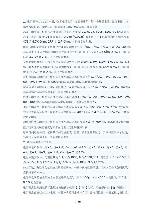
1. 电阻器种类: 晶片电阻, 碳素皮膜电阻, 金属膜电阻, 氧化金属膜电阻, 线绕电阻, 功率型线绕电阻, 水泥电阻, 厚膜排列电阻, 保险丝型金属膜电阻.晶片电阻种类: 依照其尺寸及额定功率区分为0402, 0603, 0805, 1206等. (需注意其尺寸为英制, 如0402即长乘宽为0.04in*0.02in) 其本体上有3位数码为电阻值代号如472为4.7K Ohm, 2R7 为2.7 Ohm. 其他规格如附表.碳素皮膜电阻种类: 依照其尺寸及额定功率区分为1/8W, 1/4W, 1/2W, 1W, 2W, 3W等. 其本体上有4条色码为电阻值及误差值代号如黄紫红金为4.7K Ohm 5 %, 红紫金红为2.7 Ohm 2 %. 其他规格如附表.金属膜电阻种类: 依照其尺寸及额定功率区分为1/8W, 1/4W, 1/2W, 1W, 2W 等. 其本体上有5条色码为电阻值及误差值代号如黄紫黑棕金为4.7K Ohm 5 %, 红紫黑银红为2.7 Ohm 2 %. 其他规格如附表.氧化金属膜电阻种类: 依照其尺寸及额定功率区分为1/4W, 1/2W, 1W, 2W, 3W, 4W, 5W, 7W, 10W等. 其本体标示同碳素皮膜电阻. 其他规格如附表.保险丝型金属膜电阻种类: 依照其尺寸及额定功率区分为1/4W, 1/2W, 1W, 2W, 3W等. 其本体标示同碳素皮膜电阻. 其他规格如附表.线绕电阻种类: 依照其尺寸及额定功率区分为1/2W, 1W, 2W, 3W, 4W, 5W, 6W, 7W, 8W, 10W等. 其本体标示同碳素皮膜电阻. 其他规格如附表.水泥电阻种类: 依照其尺寸及额定功率区分为2W, 3W, 5W, 7W, 10W, 15W, 20W等. 其本体直接标示阻值, 功率值及误差值代号如4K7 J 2W为4.7 K ohm 5 % 2W . 其他规格如附表.功率型线绕电阻种类: 依照其尺寸及额定功率区分为5W 至50W等. 其本体直接标示阻值, 功率值及误差值代号如水泥电阻. 其他规格如附表.厚膜排列电阻种类: 依照其排列电阻型式, 数量, 及额定功率区分. 其本体直接标示阻值, 功率值及误差值代号. 其他规格如附表.2. 电阻器主要电气规格电阻器色码代号: 黑=0, 棕=1或1%, 红=2或2%, 橙=3, 黄=4, 绿=5, 蓝=6, 紫=7, 灰=8, 白=9, 金=-1或5%, 银=-2 或10%电阻器英文代号: 电阻值R为0.1, K为1000, M为1000,000. 误差值E为+/-0.5%, F 为+/-1%, G为+/-2%, J为+/-5%, K为+/-10%, M为+/-20%.如上所述, 电阻器之电阻值及误差值规格, 一般均视电阻器类别, 以英文代号或色码代号, 直接标示於本体上.电阻器之误差值受限於本身温度系数之变化, 例如100ppm在+/-25℃变化下, 即产生0.5%之误差值.电阻器之过负载试验标准规格为加额定电压2.5 倍5秒后, 阻值变化在1% 范围内.电阻器之最高额定工作电压, 与其种类及额定功率有关, 需特别注意. 一般工程人员仅考虑实际使用功率, 未注意工作电压之上限.保险丝型金属膜电阻熔断时间规格为(16倍额定功率下2 Min.) (24倍额定功率下1 Min.) (32倍额定功率下30 Sec.)晶片电阻Chip Resistor型号0402060308051206尺寸inch0.04L*0.02W 0.06L*0.03W 0.08L*0.05W 0.12L*0.06W 额定功率1/16W1/16W1/10W1/8W温度系数200ppm/℃200ppm/℃100ppm/℃100ppm/℃额定电压25V50V100V100V过载电压50V100V200V200V温度范围-55℃--+125℃-55℃--+125℃-55℃--+125℃-55℃--+125℃零阻电流1Amp1Amp2Amp2Amp阻值误差F/G/JF/G/JF/G/JF/G/J种类Carbone FilmMetal FilmMetal Oxide FilmFusible Metal Film额定功率1/8 1/4 1/2 1 2 3 W1/8 1/4 1/2 1 2W1/4 1/2 1 2 3 4 5 7 10W1/4 1/2 1 2 3 W温度系数+300/_1000 ppm+/_25/50/100ppm+/_100/200/300ppm+/_50/100/200ppm额定电压200/250/350/500/--/--V200/250/350/--/500V250/350/--/--/500/--/750/--/--V 200/250/350/500/-- V过载电压2 * Rated 1% 2 * Rated 2 % 2 * Rated 0.5% 2 * Rated 2% 阻值误差G, J.E, F, G, J. F, G, J.F, G, J.阻值范围1 Ohm1 Ohm-5.1M Ohm0.1 Ohm-150K Ohm0.22 Ohm-100K Ohm种类Resistor NetworkWire WoundCementPower Wire Wound额定功率1/8 1/4 W (4-14 Pins)1/2 1 2 3 4 5 6 7 8 10W2/3/5/7/10/15/20 W5W-500W温度系数+/_100-250ppm+/_100/200/300ppm+/_100/200/300ppm+/_20-400ppm额定电压100/200V150/350/--/500/750/1000/--V 过载电压2.5 * Rated 0.5%2.5 * Rated 2%2.5 * Rated 2%2.5 * Rated 2%阻值误差F, G, J.F, G, J, K.F, G, J, K.F, G, J, K.阻值范围10 Ohm0.01 Ohm-10K Ohm0.01 Ohm-150K Ohm0.5 Ohm-150K Ohm碳素皮膜电阻金属膜电阻金属膜电阻氧化金属膜电阻水泥电阻Carbone-film Metal-film Metal-film Metal-oxide film Cement功率型线绕电阻厚膜排列电阻晶片电阻线绕电阻保险丝型金属膜电阻Power Wire-wound Resistor Network Chip Wire-wound Fusible Metal-film133R是133欧(这是英国标法)英文字代表误差,G=2%、F=1%、D=0.5%、C=0.2 5%、B=0.1%、A(或Ω)=0.05%、Q=0.02%、T=0.01%、V=0.005%。
精密电阻电容电感选型手册,Resistor 电阻Automotive GradeNew Resistance TCR Product Type Series SPEC Tolerance Size Product Range (ppm/?)Automotive Grade ThinFilm Precision Chip 0402/0603/0805Resistor AR..A 10Ω~1MΩ ?0.05%~?1% 25/50 1206/1210 汽车等级高精密薄膜芯片2010/2512电阻Automotive Grade Chip 0402/0603/0805/1206 Resistor CR..A1Ω~100MΩ ?0.1%~?5%, 100/200/400 1210/2010/2512 汽车等级厚膜芯片电阻Automotive GradeAnti-Sulfurated Chip 0402/0603/0805/1206 AS..A1Ω~10MΩ ?0.5%,?1%,?5% 100/200 Resistor 1210/2010/2512汽车等级抗硫化芯片电阻Automotive Grade Current 0402/0603/0805Sensing Chip Resistor 100/150/200 1206/1210/2010 CS..A3mΩ~8000mΩ ?1%,?2%,?5% 汽车等级电流感应芯片电300/400/6002512/1225/3720阻 7520 Thin filmNew Resistance TCR Product Type Series SPEC Tolerance Size Product Range (ppm/?)0201/0402/0603 Thin Film Precision Chip Resistor 5/10/15 AR1Ω~3MΩ ?0.01%~?1% 0805/1206/1210 高精密薄膜芯片电阻 25/50 2010/2512Anti-Corrosive Thin Film 0402/0603/0805 Precision Chip Resistor PR 10Ω~1.5MΩ ?0.1%~?0.5% 15/25/50 1206/2010/2512 抗蚀高精密薄膜芯片电阻Thin Film Current Sensing Chip 0402/0603/0805 Resistor TCS50mΩ~1000mΩ ?0.5%,?1% 50/100/200 1206/2010/2512 电流感应芯片电阻Wire Bondable Chip Resistor WB 10Ω~332KΩ ?0.1%~?10% 25/50/100 0201/0402/0603 打线式芯片电阻Thin Film Anti-Sulfurated Chip TAS 24.9Ω~499KΩ ?0.05%~?1%10/15/25/50 0603/0805 Resistor曹小姐提供 010 - 5 6 0 3 4 1 9 5 viking台湾光颉提供高精密薄膜抗硫化芯片电阻Thin Film Array Chip Resistor TFAN 100Ω~33KΩ ?0.1%~?1% 10/15/25/50 0603x4 高精密薄膜芯片排阻Resistor ArrayNew TCR Product Type Series SPEC Resistance Range Tolerance Size Product (ppm/?)Thin Film Array Chip Resistor ?0.1%,?0.25% TFAN 100Ω~33KΩ10/15/25/50 0603x4 高精密薄膜芯片排阻 ?0.5%Thick Film Array Chip Resistor CN 1Ω~1MΩ ?1%,?5% 200 0402x4 厚膜芯片排阻 CNAThick Film Flat Array Chip Resistor CN-21 0201x2 10Ω~1MΩ ?5% 200 厚膜芯片平板排阻 CN-41 0201x4MELF/CarbonNew TCR Product Type Series SPEC Resistance Range Tolerance Size Product (ppm/?)Metal Film Precision Resistor 10/15/25 CSR 0.1Ω~10MΩ ?0.1%~?5% 0102/0204/0207tr> 金属精密薄膜电阻 50/100Metal Film Precision Resistor 10/15/25 CSRV 0.1Ω~1MΩ ?0.1%~?5% 0204/0207 金属精密薄膜电阻 50/100Carbon Film Resistor CFS 1Ω~1MΩ ?2%,?5% - 0204/0207/0309 碳膜无脚电阻Thick filmNew Resistance TCR Product Type Series SPEC Tolerance Size Product Range (ppm/?)01005/0201/0402 Thick Film Chip Resistor CR 1Ω~100MΩ ?0.1%~?5%50/100/200/400 /0603/0805/1206/ 厚膜芯片电阻 1210/2010/2512High Ohmic Chip Resistor HMR 110MΩ~1GΩ ?5% 500/1000 0805/1206 高阻值厚膜芯片电阻曹小姐提供 010 - 5 6 0 3 4 1 9 5 viking台湾光颉提供Pulse Withstanding Chip 0603/0805/1206 Resistor PWR1Ω~20MΩ ?0.5%~?5% 100/200 1210/2010/2512 耐突波贴片电阻Surge Withstanding Chip 0603/0805/1206 Resistor SWR1Ω~20MΩ ?5%~?20% 100/200 1210/2010/2512 抗浪涌芯片电阻High Voltage Thick Film 0402/0603/0805 Chip Resistor HVR10Ω~100MΩ ?1%,?5% 100/200/400 1206/2010/2512 耐高压厚膜芯片电阻Anti-Sulfurated Thick Film 0201/0402/0603Chip Resistor AS 1Ω~10MΩ ?0.5%,?1%,?5% 100/200 0805/1206/1210 抗硫化芯片电阻 2010/2512Trimmable Thick Film 0402/0603/0805Chip Resistor RT 1Ω~10MΩ -10%~-30% 100/200 1206/1210/2010 可雷切芯片电阻 2512 LeadedNew Resistance TCR Product Type Series SPEC Tolerance Size Product Range (ppm/?)Metal Film Leaded Precision 5/10/15/25 0318/0623/0932 Resistor MFR 0.1Ω~10MΩ ?0.05%~?1% 50/100 1145/1550 插件式金属精密电阻Me tal Film Leaded Resistor ?0.02%,?0.05%, MFD 10Ω~1MΩ 5/10/15/25 0727/1040 高精密金属膜固定电阻器 ?0.1%Carbon Film Leaded Resistor 0318/0623/0932 CFR 0.1Ω~22MΩ ?2%,?5% - 插件式碳膜电阻 1145/1550Metal Oxide Leaded Film 0623/0932/1145 Resistor MOF0.1Ω~22MΩ ?1%,?2%,?5% 200 1550/1765/2485 插件式金属氧化皮膜电阻Current sensingNew Resistance TCR Product Type Series SPEC Tolerance Size Product Range (ppm/?)0201/0402/0603 Current Sensing Chip 100/150/200/300 0805/1206/1210 Resistor CS 3mΩ~8000mΩ ?1%,?2%,?5% 400/600/1000 2010/2512/1225 电流感应芯片电阻 3720/7520 曹小姐提供 010 - 5 6 0 3 4 1 9 5 viking台湾光颉提供Thin Film Current 0402/0603/0805 Sensing Chip Resistor TCS50mΩ~1000mΩ ?0.5%,?1% 50/100/200 1206/2010/2512 薄膜电流感应芯片电阻Current Sensing Thick 0402/0603/0805 200/500/800 Film Chip Resistor RS 10mΩ~976mΩ ?1%, ?5% 1206/1210/2010 1200/1500 电流感应芯片电阻 2512Ultra Low Ohm (MetalStrip) Chip Resistor LR 0.5mΩ~15mΩ ?1%,?3%,?5% 50/75/100/1501206/2010/2512 1W~3W合金超低阻芯片电阻Chip Shunt Resistor 50/60/75 LRS 0.5mΩ~4mΩ ?1%,?2%,?5% 1050/1575分流芯片电阻 100/120Current Sensing Metal 0805/1206 Chip Resistor CSM10mΩ~100mΩ ?1%,?2%,?5% 50/100 2010/2512 电流感应金属芯片电阻Low Ohm (Metal Strip)Chip Resistor LRM 5mΩ~100mΩ ?1%,?2%,?5% 75/100 1206/2010/2512 合金低阻芯片电阻Power resistorPower ResistorNew TCR Product Type Series SPEC Resistance Range Tolerance power Product (ppm/?)TO-220 Power Resistor ?0.5%,1%, 5%, TR20 0.05Ω~10KΩ 50/100/200/300 20W 插件式功率电阻 10%TO-220 Power Resistor ?0.5%,1%, 5%, TR30 0.05Ω~10KΩ 50/100/200/300 30W 插件式功率电阻 10%TO-220 Power Resistor ?0.5%,1%, 5%, TR35 0.05Ω~10KΩ 50/100/200/300 35W 插件式功率电阻 10%TO-220 Power Resistor ?0.5%,1%, 5%, TR50 0.1Ω~10KΩ 50/100/200/300 50W 插件式功率电阻 10%TO-247 Power Resistor ?0.5%,1%, 5%, TR100 0.05Ω~10KΩ50/100/200/300 100W 插件式功率电阻 10%曹小姐提供 010 - 5 6 0 3 4 1 9 5 viking台湾光颉提供TO-220 Power Resistor ?0.5%,1%, 5%, TR50-H 0.1Ω~10KΩ50/100/200/300 50W 插件式功率电阻 10%,Inductor 电感高频电感(RF Inductor)New Inductance Product Product Description Series SPEC Curve Tolerance SRF(MHZ) DCR(Ω) IDC(mA) Size Product RangeThin Film Chip 0201 Inductor ?0.1,0.2,0.3nH AL 0.1nH~100nH1000~14000 0.1~7.5 75~800 0402 高频薄膜精密芯片电?1%,2%,3%,5% 0603 感Multilayer Chip ?0.3nH 0402 Inductor CL 1nH~220nH 600~10000 0.1~2.7 100~500 ?5%,10% 0603 高频陶瓷积层电感Wire Wound Chip 0402Inductor 0603(Low Profile, High Q, WL 1nH~15000nH ?2%, 5%,10% 15~12700 0.02~11.5 80~2400 0805 Current, High SRF) 1008高频陶瓷绕线电感 1206功率电感(Power Inductor)New Product Inductance Product Series SPEC Tolerance DCR(Ω) I DC(A) Size Product Description RangeNon-shielded,High Power, WireWound Power ?20% 1608/1813/3316 PDH 0.47u~100uH 0.003~1.6 0.4~30 Inductor +40%-20% 4920/5022 开磁路绕线功率电感Non-shielded,Wire Wound Power 1608/3308/3316 Inductor PD 0.18u~1000uH ?20%,30% 0.007~13.8 0.1~40 3340/5022 开磁路绕线功率电感曹小姐提供 010 - 5 6 0 3 4 1 9 5 viking台湾光颉提供Non-shielded,Low Profile Wire 0301/0302/0402/0403 Wound Power PCD1.0u~1000uH ?10%,20% 0.01~10.19 0.09~9.5 0502/0503/0504/0703 Inductor 0705/1004/1005/1006 开磁路绕线功率电感Low Profile , Mini Wire Wound Power Inductor MPI 1.2u~1000uH ?20%, 0.04~22.6 0.08~2.5 0610/0612/0620 小型绕线功率电感Low Profile , Mini Wire Wound Power Inductor MPE 1u~68uH ?20%,30% 0.08~4.2 0.17~1.4 0312 小型绕线功率电感Shielded, Wire Wound Power Inductor PS 1u-10000uH ?10%,20%0.021~32.8 0.02~5 1608/3316/5022 闭磁路绕线功率电感Shielded, Wire Wound Power ?20% 62B/64B/73/74 Inductor PCS 1.2u-1000uH 0.007~9.44 0.14~9.8 +40%-20% 124/125/127 闭磁路绕线功率电感Shielded, Wire Wound Power 0628/0728/0730Inductor PCDR 1.2u~1500uH ?20%,30% 0.0069~4.78 0.13~130732/0745/1045 闭磁路绕线功率1255/1265/1275电感Shielded, Low Cost, Wire Wound Power Inductor PCDS10u~820uH ?20%,30% 0.03~2 0.33~3.15 63B/74B/105B/125B 闭磁路绕线功率电感Shielded, Low Profile Wire Wound Power 5D28 PSDB 1.3u~1000uH ?30% 0.006~1.989 0.4~10.5 Inductor 1003/1004/1005 闭磁路绕线功率电感曹小姐提供 010 - 5 6 0 3 4 1 9 5 viking台湾光颉提供Shielded, Low Profile Wire Wound Power 2D12/2D15 SCDB1.2u~47uH ?20%,30% 1.2~47 0.22~1.1 Inductor 2D18 闭磁路绕线功率电感Shielded, Low Profile Wire 3D18Wound Power 4D18/4D22/4D28 SCDS 1u~470uH ?30% 0.012~6.56 0.13~6.15 Inductor 5D18/5D28 闭磁路绕线功率6D28/6D38电感Shielded Wire 4010/4020/4030 Wound Power 5010/ 5020/5030 Inductor PCF 0.36u~10000uH ?20%,30% 0.005~201.16 0.026~12.6 6915/6919/7040 闭磁路绕线功率1015/1040/1062 电感Shielded, Low Profile Wire Wound Power 0.47u~ 0302/0303/0418PDRH ?20%,30% 0.009~175.4 17~4820 Inductor 27000uH 0501/0502/0503 闭磁路绕线功率电感Shielded, Wire Wound Power Inductor SDRH 1.0u~100uH ?30% 0.0095~0.43 0.75~9 0830/0840/0845 闭磁路绕线功率电感Shielded, Wire Wound Power Inductor SDB 0.10u~47uH ?20% 0.0015~0.210 1.2~32.5 0630/1040 闭磁路绕线功率电感Miniature Wire Wound Power 0312/0412/0612 Inductor SDIA1u~100uH ?20% 0.016~60 0.05~8.16 0820/0825/0840 小型绕线功率电感Shielded, 201609E/201514 Non-shielded, ?5%,10% 321618C/322515 Miniature Wire VLH 0.1u~10000uH 0.0098~140 0.023~50 ?20%,30%322520C/453226C Wound Power 575047C Inductor曹小姐提供 010 - 5 6 0 3 4 1 9 5 viking台湾光颉提供小型绕线功率电感Shielded, LowProfile Wire 2D10/2D15/2D18 SCDA 0.47uH~100uH ?20%,?30% 0.035~3.840.18~3.9 Wound Power 3D12/3D15/3D18 Inductor磁芯电感(Ferrite Inductor)New Product Inductance Product Series SPEC Tolerance SRF(MHZ) DCR(Ω) IDC(mA) Size Product Description RangeMultilayerFerrite ChipInductor ML 0.01~33uH ?10%,20% 13~320 0.15~2.55 5~300 0603/0805/1206 积层芯片式黑电感Multilayer 0402/0603/0805/1204 Chip Bead CB 5~2700Ω ?25% - 0.01~250~6000 1206/1210/1808/1812 贴片磁珠Wound ChipInductors(Ferrite) ?5%,10% 0805/1008/1210 NL 0.12uH~1000uH 0.5~800 0.03~150 30~1800 铁芯绕线电感?20% 1812/2220 (开放,铸膜及背胶)Chip CommonMode Choke CM 67~2200Ω ?20% - 0.25~1.2 200~400 0805/1206 共模滤波器插件式电感(DIP Power Inductor)New Product Inductance Product Series SPEC Tolerance DCR(Ω) IDC(A) Size Product Description RangeDIP PowerInductor DRGH 10u~47000uH ?10%,20% 0.022~96.4 0.038~5.3664/855/875/895/106/108/110 插件式开磁路功率电感曹小姐提供 010 - 5 6 0 3 4 1 9 5 viking台湾光颉提供DIP PowerInductor DRGR 10u~10000uH ?10%,20% 0.023~35 0.074~3.51664/875/108/110 插件式闭磁路功率电感DIP Power 0708/0808/1210 DM 0.22u~33uH ?20% 0.0006~0.025 6~56 Inductor 1310/1818,Capacitor 电容积层电容(SMD Capacitor)New Product Capacitance Picture Series SPEC Tolerance Voltage Material Size Product Description Range Multilayer ?0.1,0.25,0.5pF Ceramic 6.3V,10V,16V NPO/X7R 0402/0603/0805 MC-1 0.5pF~100uF ?5%,10%,20% Capacitor 25V,50V,100V X5R/Y5V 1206/1210/1812 -20/+80% 迭层贴片电容MultilayerCeramicCapacitor ?0.25,0.5pF (Middle & 200V,250V,500V NPO/X7R0603/0805/1206 MC-2 0.5pF~0.68uF ?5%,10%,20% High 630V,1KV,2KV,3KV Y5V 1210/1808/1812 -20/+80% Voltage)中高壓迭层贴片电容MultilayerCeramicCapacitor ?0.25,0.5pF 6.3V,10V,16V NPO/X7R (Ultra-Small MC-30.3pF~0.1uF 0201 ?5%,10%,20% 25V,50V X5R Capacitor)小型迭层贴片电容MultilayerCeramicCapacitor ?0.1,0.25,0.5pF MCHL 0.5pF~3300pF 16V,25V,50V,100V NPO0402/0603/0805 (High Q, Low ?5%ESR)迭层贴片电容Multilayer ?0.05,0.1,0.25,0.5pF 6.3V,10V,25V 0201/0402/0603 Ceramic MCRF 0.1pF~100pF NPO ?1%,2%,5% 50V,100V,250V 0805 Capacitor曹小姐提供 010 - 5 6 0 3 4 1 9 5 viking台湾光颉提供(Ultra HighQ, Low ESR)高频迭层贴片电容MultilayerCeramicCapacitor(Low MCLI 10nF~150nF ?10%,20% 50V X7R 0612 Inductance)低感迭层贴片电容------------------------------ 咨询及样品申请,请联系光颉viking代理: 曹小姐提供**************************曹小姐提供 010 - 5 6 0 3 4 1 9 5 viking台湾光颉提供。
贴片电阻对应尺寸表贴片电阻是一种常见的电子元器件,广泛应用于各种电子设备中。
在选择适合的贴片电阻时,我们需要参考贴片电阻对应尺寸表,以确保选取的电阻尺寸符合设计要求。
一、贴片电阻的尺寸参数贴片电阻的尺寸通常由长度、宽度和厚度三个参数来描述。
以毫米为单位,常见的尺寸范围如下:1. 长度(L):从0.5mm到7.0mm不等。
2. 宽度(W):从0.125mm到5.0mm不等。
3. 厚度(T):从0.2mm到1.5mm不等。
根据实际需求,我们可以根据贴片电阻对应尺寸表来选择合适的尺寸。
二、贴片电阻尺寸的选择1. 小尺寸电路板:对于小尺寸的电路板,为了节省空间,我们可以选择较小尺寸的贴片电阻。
例如,长度为1.0mm、宽度为0.5mm、厚度为0.2mm的贴片电阻,可以满足空间限制的要求。
2. 大功率负载:对于需要承受较大功率负载的电路,我们需要选择具有较大尺寸的贴片电阻,以确保其能够承受高功率的工作条件。
例如,长度为5.0mm、宽度为3.2mm、厚度为1.5mm的贴片电阻,具有较高的功率承受能力。
3. 精密测量电路:对于需要高精度测量的电路,我们需要选择具有较小尺寸和较高稳定性的贴片电阻。
例如,长度为0.5mm、宽度为0.125mm、厚度为0.2mm的贴片电阻,具有较小的尺寸和较高的稳定性。
三、贴片电阻的尺寸与功率的关系贴片电阻的尺寸与其能够承受的功率有一定的关系。
一般来说,尺寸越大的贴片电阻,其功率承受能力也越大。
因此,在选择贴片电阻时,我们需要根据实际功率需求来确定合适的尺寸。
四、贴片电阻的尺寸对焊接工艺的影响贴片电阻的尺寸也会对焊接工艺产生影响。
较小尺寸的贴片电阻在焊接时需要更高的精度和技术要求,以确保焊接的质量。
而较大尺寸的贴片电阻则相对容易焊接。
五、贴片电阻尺寸的标准化为了方便选择和应用,贴片电阻的尺寸已经得到了标准化。
根据不同的国际标准,贴片电阻的尺寸参数可能会有所差异。
因此,在选择贴片电阻时,我们需要参考相应的标准,以确保选取的贴片电阻符合国际规范。
贴片电阻Fixed Chip Resistors,ChipR简述 (2)贴片电阻基本结构 (2)贴片电阻分类 (4)贴片电阻规格、封装、尺寸 (4)贴片电阻额定功率及工作电压 (5)贴片电阻标识 (6)常规3位数标注法:XXY (7)常规4位数标注法:XXY (7)3位数乘数代码(Multiplier Code)标注法:XXY (7)贴片电阻生产厂家、规格书 (11)贴片电阻命名方法 (11)贴片电阻的参考价格 (12)简述我们常说的贴片电阻(SMD Resistor)叫"片式固定电阻器"(Chip Fixed Resistor),又叫"矩形片状电阻"(Rectangular Chip Resistors),是由ROHM公司发明并最早推出市场的。
特点是耐潮湿,耐高温,可靠度高,外观尺寸均匀,精确且温度系数与阻值公差小。
按生产工艺分厚膜(Thick Film Chip Resistors)、薄膜(Thin Film Chip Resistors )两种。
厚膜是采用丝网印刷将电阻性材料淀积在绝缘基体(例如玻璃或氧化铝陶瓷)上,然后烧结形成的。
我们通常所见的多为厚膜片式电阻,精度范围±0.5% ~ 10%,温度系数:±50PPM/℃~ ±400PPM/℃。
薄膜是在真空中采用蒸发和溅射等工艺将电阻性材料淀积在绝缘基体工艺(真空镀膜技术)制成,特点是低温度系数(±5PPM/℃),高精度(±0.01%~±1%)。
封装有:0201,0402,0603,0805,1206,1210,1812,2010,2512。
其常规系列的精度为5%,1%。
阻值范围从0.1欧姆到20M欧姆。
标准阻值有E24,E96系列。
功率有1/20W、1/16W、1/8W、1/10W、1/4W、1/2W、1W。
特性:•体积小,重量轻•适合波峰焊和回流焊•机械强度高,高频特性优越•常用规格价格比传统的引线电阻还便宜•生产成本低,配合自动贴片机,适合现代电子产品规模化生产使用状况:由于价格便宜,生产方便,能大面积减少PCB面积,减少产品外观尺寸,现在已取代绝大部分传统引线电阻。
村田贴片电阻规格书
村田贴片电阻规格书是电子元件中常见的一种电阻器,具有小巧、高可靠性和稳定性等特点。
该规格书提供了详细的电阻参数和性能指标,以帮助工程师选择合适的电阻器,并确保电路设计和性能满足要求。
我们从电阻器的尺寸和形状开始。
村田贴片电阻器通常采用矩形形状,具有标准的尺寸和厚度,以方便在电路板上焊接。
这种设计使得电阻器在各种电子设备中易于安装和使用。
规格书提供了电阻器的电阻值范围。
村田贴片电阻器的电阻值通常在欧姆(Ω)单位下测量,并且在规格书中以一定的公差范围表示。
公差范围用于描述电阻器的精度和稳定性,这对于电路的性能和稳定性至关重要。
规格书还会列出电阻器的功率额定值。
功率额定值表示电阻器可以承受的最大功率,超过该值可能导致电阻器过热和损坏。
因此,在选择电阻器时,工程师需要根据电路的功率要求和环境条件选择合适的功率额定值。
规格书还提供了电阻器的温度系数。
温度系数是电阻器随温度变化而产生的电阻变化的比率。
这对于一些对温度敏感的应用非常重要,例如汽车电子设备或工业控制系统。
规格书还列出了电阻器的包装方式和包装数量。
这有助于供应商和
制造商根据需求进行订购和生产。
村田贴片电阻器通常以卷装或盘装的方式提供,以适应不同规模的生产需求。
村田贴片电阻规格书为工程师提供了详细的参数和性能指标,以帮助他们选择合适的电阻器,并确保电路设计和性能满足要求。
通过仔细阅读规格书,工程师可以了解电阻器的尺寸、电阻值范围、功率额定值、温度系数等重要信息,从而确保电子设备的稳定性和可靠性。