风华RV高压贴片电阻器规格书 选型手册
- 格式:pdf
- 大小:2.09 MB
- 文档页数:9

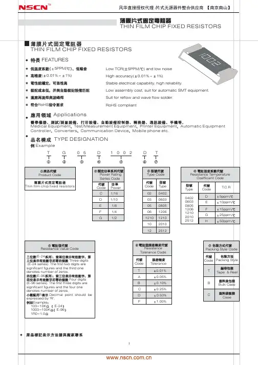
广东风华高新科技股份有限公司GUANGDONG FENGHUA ADV ANCED TECHNOLOGY HOLDING CO.,LTD.承认书APPROV AL SHEET客户名称:CUSTOMER品名:常规厚膜片式固定电阻器PARTNAME规格版本号VERSION日期DATE制造客户APPROV AL APPROV AL 拟制审核确认检验审核批准FENGHUAFENG HUA ADV ANCED TECHNOLOGY (HOLDING) CO., LTD序号 No 目 录TABLE OF CONTENTS1.0 概述Summary2.0 结构及尺寸Structure And Dimensions3.0 型号规格表示办法How To Order4.0 电气性能Performance Specification5.0 可靠性Reliability Data6.0 包装Package7.0 环保情况说明 Environmental Protection Statement 8.0 推荐使用的焊接曲线Recommended soldering profile 9.0 使用注意事项Precautions For UseRC/RS□□□□1.0概述Summary片式电阻器主要生产的型号包括01005、0201、0402、0603、0805、1206、1210、2010、2512。
其特点是:The dimension type for chip resistor including01005、 0201、0402、0603、0805、1206、1210、2010、2512, and the features are as below:*体积小、重量轻miniature and light weight*电性能稳定,可靠性高 stable electrical capability and high reliability *机械强度高、高频特性优越superior mechanical and frequency*装配成本低,并与自动贴装设备匹配low assembly cost, suit for automatic SMT *适应再流焊与波峰焊suit for re-flow and wave flow soldering .*符合ROHS指令要求Compliant with ROHS Directive*符合无卤素要求Compliant with halogen free requirement*禁止使用SS-00259中规定的1级环境管理物质*SONY指定原材料只能从绿色伙伴认定供应商处采购产品广泛应用于计算机、通讯、工业自动化、航天航空、军事、数字电视、数字音响及消费类电子等领域。
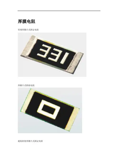
厚膜电阻
常规厚膜片式固定电阻
厚膜片式跨接电阻
超低阻值厚膜片式固定电阻
高阻值厚膜片式固定电阻
高精度厚膜片式固定电阻
抗硫化厚膜片式固定电阻器
功率型厚膜片式固定电阻器
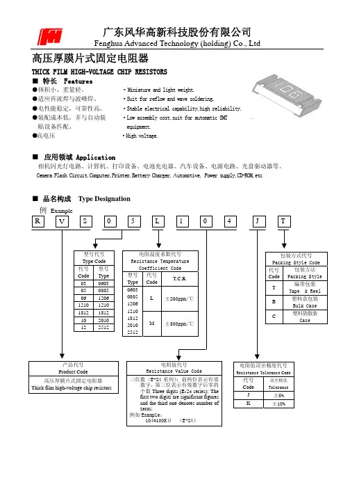
厚膜高压片式固定电阻器
低TCR超低阻值厚膜片式固定电阻器
抗浪涌厚膜片式固定电阻器
软灯条厚膜片式固定电阻器
低铅厚膜片式固定电阻器
超小尺寸厚膜片式固定电阻器
厚膜网络电阻
厚膜片式网络电阻
低铅厚膜片式网络电阻
厚膜网络电阻
合金片式固定电阻器
合金超低阻值片式固定电阻
热敏电阻
厚膜片式负温度系数电阻(NTC热敏电阻)
PTC插件热敏电阻
NTC插件热敏电阻
高精度AT型NTC热敏电阻
高精度玻封NTC热敏电阻
压敏电阻
多层片式压敏电阻
片式压敏电阻排
氧化锌压敏电阻
钛酸锶环形压敏电阻
定制电阻
油位传感器用厚膜电阻板
机油压力传感器用厚膜电阻板
节气门位置传感器用厚膜电阻板
空调风门执行器用厚膜电阻板
激光打印机用陶瓷加热电阻条
厚膜高压电阻器
色环电阻
碳膜电阻
金属膜电阻
金属氧化膜电阻
水泥电阻
绕线电阻。
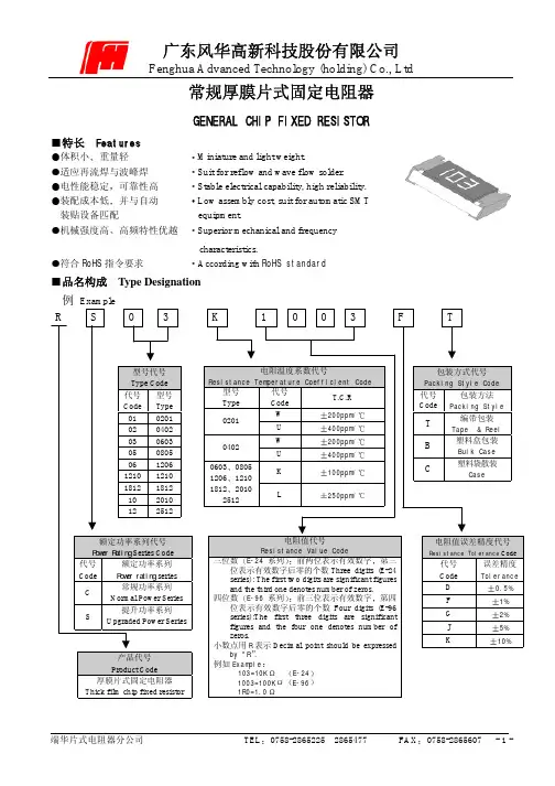
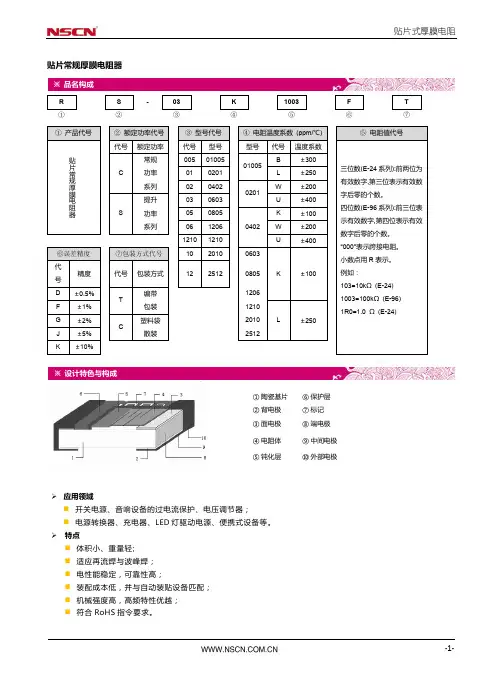
常规厚膜片式固定电阻器GENERAL CHIP FIXED RESISTOR特长 Features体积小重量轻Miniature and light weight.适应再流焊与波峰焊Suit for reflow and wave flow solder.电性能稳定可靠性高Stable electrical capability, high reliability.装配成本低并与自动Low assembly cost, suit for automatic SMT装贴设备匹配equipment.机械强度高高频特性优越Superior mechanical and frequencycharacteristics.符合RoHS指令要求According with RoHS standard品名构成 Type Designation例Example200ppm/400ppm/200ppm/400ppm/100ppm/0603080512061210181220102512250ppm/Resistance Value Code三位数E-24系列前两位表示有效数字第三位表示有效数字后零的个数Three digits (E-24series): The first two digits are significant figuresand the third one denotes number of zeros.四位数E-96系列前三位表示有效数字第四位表示有效数字后零的个数Four digits (E-96series):The first three digits are significantExample103=10K E-241003=100K E-961R0=1.00.5%1%2%5%10%结构及规格尺寸Construction and dimension单位Unit: mm 型号Type L W t a b 0201 0.600.05 0.300.05 0.230.05 0.100.05 0.150.05 0402 1.000.10 0.500.10 0.300.10 0.200.10 0.250.10 0603 1.600.15 0.800.15 0.400.10 0.300.20 0.300.20 0805 2.000.20 1.250.15 0.500.10 0.400.20 0.400.20 1206 3.200.20 1.600.15 0.550.10 0.500.20 0.500.20 1210 3.200.20 2.500.20 0.550.10 0.500.20 0.500.20 1812 4.500.20 3.200.20 0.550.10 0.500.20 0.500.20 2010 5.000.20 2.500.20 0.550.10 0.600.20 0.600.20 2512 6.400.20 3.200.20 0.550.10 0.600.20 0.600.20产品外观Appearance1.电阻器表面二次玻璃体保护膜覆盖完好且难以脱落,表面平整The surface of resistor is covered with Protective Coating which hard to fade, and the surface of coating should avoid unevenness.2.电阻器引出端电极覆盖均匀镀层较难脱落且平整无裂痕针孔变色The terminal part is covered equable , the plating is hard to fade, and should avoid unevenness, flaw, pinhole and discoloration.3.电阻器芯片无裂痕标志可辨With a clear mark , the resistor body is crack-free.参考标准 Reference StandardGB/T 5729-2003GB/T 9546-1995JIS C 5223-1995JIS C 5201-1998JIS C 5202-1990负荷下降曲线Derating Curve755025使用温度范围OperatingTemperatureRange-55125环境温度Ambient temperature ()当电阻使用的环境温度超过70时其额定负荷(额定电压)按上述曲线下降For resistors operated in ambient over 70,rated load (power rating) shall be derated in accordance with the above figure.额定值 Ratings项目 Item 0201 0402 06030805 1206 1210 1812 20102512常规功率系列Normal PowerSeries1/20W 1/16W1/16W1/10W1/8W 1/4W 1/2W 1/2W1W 额定功率Power Rating提升功率系列Upgraded PowerSeries/ /1/10W1/8W1/4W1/3W/ 3/4W/最大工作电压VMax.Working Voltage25 50 50 150200 200 200 200 200最大过负荷电压VMax.Overload Voltage50 100 100 300400 400 400 400 400电阻温度系数Resistance TemperatureCoefficient10R 1M:200ppm/1R<10,1M<R10M:400ppm/10R1M:100ppm/1R<10,1M<R10M:250ppm/阻值范围Resistance Range1~10ME-24E-96系列阻值误差精度Resistance Tolerance5%10%1~10M: 1%2%5%10%10~1M:0.5%1~10M: 1%2%5%10%10~1M:0.5%1% 2% 5%10% 使用温度范围Operating Temperature Range-55~+125额定温度Rated Temperature70注额定电压=额定功率标称电阻值或最大工作电压两者中的较小值Note Rated Voltage=Power Rating Resistance Value or Max. Working Voltage , whichever is lower.特性 Characteristics项目Item标准Specifications测试方法JIS C 5202标准Test Methods (JIS C 5202)端头强度Bending Strength无可见损伤No mechanical damageR 1.0%R+0.05弯曲速度(Speed):1mm/s弯曲距离(Bending Distance):0201040206030805120612103mm1812201025121mm电阻温度系数T.C.R在规定值内within specified T.C.R测定范围-55~+125Measure between -55~+125温度循环TemperatureCycling无可见损伤No mechanical damageR 1.0%R+0.05-5530分钟~常温5分钟~12530分钟5个循环-5530min~normal temperature5min~12530min 5 cycles短时间过负载Short TimeOverload无可见损伤No mechanical damageR 2.0%R+0.052.5倍额定电压或最大过负荷电压取最小者保持5秒2.5Rated voltage or Max. Overload Voltagewhichever is lower for 5 seconds续上表稳态湿热Steady state humidity无可见损伤No mechanical damage R 3.0%R+0.1 40290~95RH 1000小时 402 90~95RH 1000h70耐久性 Load Life无可见损伤No mechanical damageR 3.0%R+0.17021000小时额定电压通1.5小时/断0.5小时7021000hRated voltage 1.5h on/0.5h off上限类别温度耐久性 Endurance atupper temperature 无可见损伤No mechanical damageR 3.0%R+0.11252 1000h 耐溶剂性Resistance toSolvent无可见损伤 No mechanical damage R 1.0%R+0.05 浸入三氯乙烯 10h 1hDip in chloroethylene for 10h 1h .绝缘电阻Insulation Resistance1000M Min在电极与基片间施加100V 直流电压,保持1分钟,然后测绝缘电阻值.Apply DC 100V between substrate and terminationfor 1 minute, then check insulation resistance .耐焊接热 Resistance toSoldering Heat无可见损伤No mechanical damageR 1.0%R+0.052605 10s 1s 可焊性Solderability 可焊面积95% 95% Cover Min2355 2s 0.5s 附着力Adhesion 外观无可见损伤 No mechanical damage 施加力5N 10s 1s Applying 5N 10s 1s包装 Packaging编带包装 Tape and reel * 纸带编带 Paper taping 020104020603080512061210单位unit: mm 型号Type A B W F E 0201 0.700.1 0.400.1 8.00.20 3.50.05 1.750.10402 1.200.1 0.700.1 8.00.20 3.50.05 1.750.10603 1.850.1 1.100.1 8.00.20 3.50.05 1.750.10805 2.350.1 1.650.1 8.00.20 3.50.05 1.750.11206 3.500.2 1.900.2 8.00.20 3.50.05 1.750.11210 3.500.2 2.800.2 8.00.20 3.50.05 1.750.1单位unit: mm 型号Type P P0 P1 ФD0 T 0201 2.00.05 4.00.1 2.00.05 1.50.1 0.5Max0402 2.00.05 4.00.1 2.00.05 1.50.1 0.6Max0603 4.00.1 4.00.1 2.00.05 1.50.1 0.600.10805 4.00.1 4.00.1 2.00.05 1.50.1 0.750.11206 4.00.1 4.00.1 2.00.05 1.50.1 0.750.11210 4.00.1 4.00.1 2.00.05 1.50.1 0.750.1*塑料带编带 Embossed taping单位unit: mm型号Type A0 B0WFEt 1812 4.800.10 3.400.10 12.000.10 5.500.10 1.750.10 0.250.05 2010 5.450.10 2.770.10 12.000.10 5.500.10 1.750.10 0.240.05 25126.730.10 3.400.10 12.000.10 5.500.10 1.750.10 0.240.05单位unit: mm型号Type PP0P1 ФD0ФD1K0 1812 4.000.10 4.000.10 2.000.05 1.550.10 1.500.10 1.000.10 2010 4.000.10 4.000.10 2.000.05 1.50+0.10/-0 1.500.10 0.840.10 25124.000.10 4.000.10 2.000.051.50+0.10/-0 1.500.100.810.10* 卷盘 Reel单位unit: mm型号Type MWTABCD0201 0402 0603 0805 1206 1210 178 2.09.5 1.012.5 1.52.0 0.513.0 0.521.0 0.558.0 2.01812 2010 2512178 2.013.0 0.515.5 1.52.0 0.513.0 0.521.0 0.557.0 2.0*塑料盒包装Bulk case单位unit:mm包装数量 Packaging quantity包装方法Packagingstyle编带Tape and reel塑料盒Bulk case塑料袋散装Bulk型号Type 020104020603080512061210181220102512020104020603 0805 12061210201018122512020104020603080512061210181220102512数量PCSQuantity10000 5000 4000 50000 25000 10000 5000 1500 1000 50000 10000 4000。
华瓷贴片电容规格书
华瓷贴片电容是一种常见的电子元件,常用于电子电路中。
规
格书通常包括以下内容:
1. 产品型号和规格,规格书会列出华瓷贴片电容的型号,包括
尺寸、容量、额定电压、温度系数等信息。
这些信息对于电路设计
和元件选择非常重要。
2. 电气特性,规格书会详细说明华瓷贴片电容的电气特性,包
括介电常数、损耗因子、绝缘电阻、极化特性等。
这些参数对于元
件在电路中的实际应用至关重要。
3. 使用环境,规格书通常会包括华瓷贴片电容的使用环境要求,例如工作温度范围、存储温度范围、湿度要求等。
这些信息对于元
件的可靠性和稳定性至关重要。
4. 封装和外形,规格书会描述华瓷贴片电容的封装形式、外形
尺寸、引脚排列等信息,这些信息对于PCB布局和焊接工艺非常重要。
5. 其他特性,规格书还可能包括一些其他特性,如耐久性、可靠性指标、环保要求等。
总的来说,规格书是工程师和设计师在选型和使用华瓷贴片电容时的重要参考依据,能够帮助他们更好地理解和使用这种电子元件。
RVT Series HUAHUI HIGH VOLTAGE,LONG LIFE高壓長壽命品Operating with wide temperature range-40~+105°C適用於-20~+105°C的寬溫範圍Load life of5000hours負荷壽命5000小時Comply with the RoHS directive符合RoHS指令SPECIFICATIONS特性表Items項目Operation Temperature Range使用温度範圍Voltage Range額定工作電壓範圍Capacitance Range靜電容量範圍Capacitance Tolerance靜電容量允許偏差Leakage Current漏電流Dissipation Factor(tan)損耗角正切Stability at LowTemperature低溫特性Load Life高溫負荷特性Characteristics主要特性-40~+105°C160~450V1~47μF±20%at120Hz,20°CLeakage current≤0.04CV+100μA,whichever is greater(after2minutes application of rated voltage)漏電流≤0.04CV+100μA,取較大值(施加額定工作電壓2分鐘後)Measurement frequency測試頻率:120Hz,Temperature温度:20°CRated Voltage(V)額定工作電壓160~250400,500 tanδ(max.)最大損耗角正切0.150.20 Measurement frequency測試頻率:120HzRated Voltage(V)額定工作電壓160~250400,500 Impedance Ratio阻抗比Z(-25°C)/Z(20°C)36 ZT/Z20(max.)Z(-20°C)/Z(20°C)610 After5000hours application of the rated voltage at105°C,they meet the characteristics listed below.在105°C環境中施加額定工作電壓5000小時後,電容器的特性符合下表的要求。
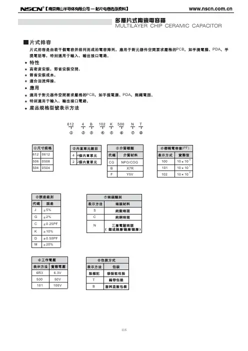
MULTILAYER CHIP CERAMIC CAPACITOR(:)DC Medium-voltage MLCCDC medium-voltage MLCC has good high-voltage reliability,it is made in special design that based on the MLCC technology and equipments.It is suitable for surface-mounting ,can improve the properties of circuits.New monolithic structureThe size of the capacitor is small,yet has high electrostatic capacitance,can operate at high-voltage levels.Has good solderability.Technology Parameter (refer to the picture below):DC-DC converter.The circuit filter and vibration bell of telephone,electrograph and modem.Snubber circuit for switching power supply.FeaturesApplicationsProduct Part Number Expression1206CG100J202NTWMULTILAYER CHIP CERAMIC CAPACITORCapacitance RangeOutside DimensionWMULTILAYER CHIP CERAMIC CAPACITORMULTILAYER CHIP CERAMIC CAPACITORMULTILAYER CHIP CERAMIC CAPACITOR【 南京南山半导体有限公司 — 贴片电容选型资料】MULTILAYER CHIP CERAMIC CAPACITORX7R 1808 (V)10018122225200 200 200 5001000 2000 3000 4000 100 500 1000 2000 3000 4000 100 500 1000 2000 3000 4000 5000 /250 /250 /250100PF 150PF 330PF 470PF 680PF 1000PF 1nF 2.2nF 3.3nF 4.7nF 6.8nF 10nF 12nF 15nF 22nF 27nF 33nF 39nF 47nF 56nF 68nF 100nF 120nF 150nF 220nF 270nF 330nF 470nF 680nF 1 F 2.2 F 3.3 F 10 F 22 F75【 南京南山半导体有限公司 — 贴片电容选型资料】ItemX7R Medium-voltage MLCCDielectric 1808 1812 2225 Size Rated 100 200 5001000 2000 3000 4000 100 200 500 1000 2000 3000 4000 100 200 500 1000 2000 3000 4000 5000 /250 /250 Volatage(V) /250 Capacitance 100PF 150PF 330PF 470PF 680PF 1000PF 1nF 2.2nF 3.3nF 4.7nF 6.8nF 10nF 12nF 15nF 22nF 27nF 33nF 39nF 47nF 56nF 68nF 100nF 120nF 150nF 220nF 270nF 330nF 470nF 680nF 1 F 2.2 F 3.3. F 10 F 22 F76【 南京南山半导体有限公司 — 贴片电容选型资料】MULTILAYER CHIP CERAMIC CAPACITORY5V 0603 (V) 100 100 0805 200 250 100 1206 200 250 100 1210 200 250 100 1812 200 250 100 2225 200 2501000PF 1.5nF 2.2nF 3.3nF 4.7nF 6.8nF 10nF 12nF 15nF 22nF 27nF 33nF 39nF 47nF 56nF 68nF 100nF 150nF 220nF 270nF 330nF 390nF 470nF 680nF 820nF 1 F 2.2 3.3 10 F F F77【 南京南山半导体有限公司 — 贴片电容选型资料】ItemY5V Medium-voltage MLCC 1210 100 200 250 100 1812 200 250 100 2225 200 250Dielectric 0603 0508 1206 Size Rated Volatage(V) 100 100 200 250 100 200 250 Capacitance 1000PF 1.5nF 2.2nF 3.3nF 4.7nF 6.8nF 10nF 12nF 15nF 22nF 27nF 33nF 39nF 47nF 56nF 68nF 100nF 150nF 220nF 270nF 330nF 390nF 470nF 680nF 820nF 1 2.2 3.3 10 F F F F78【 南京南山半导体有限公司 — 贴片电容选型资料】MULTILAYER CHIP CERAMIC CAPACITORCOG1-551251. 2. 3. 2 4. , , , , , 105.3 4 :HP4278A 1. 2. 5 (D.F.) 3. HP4284 25 5 :30% 75% 1.0 0.2V C<1000PF,1.0 0.1MHz; C 1000PF,1.0 0.1KHZ :10( :SF2511) >500V6I.R. 500V: , 60 5>1 5 7 >1 2 >1 21000V 1000V 2000V 2000V50mA 50mA 10mA 150+0/-10 60 55S 5S 5S824 2 -55 125 25975235 5 5 2 0.5 150+0/-10 5% 0.5PF, 10 1 D.F. 24 2 265 5 24 2 25 2.5mm/ : 25 2.5mm/ 60 524510I.R.1 2100 170120 2001 179【 南京南山半导体有限公司 — 贴片电容选型资料】Middle and high Voltage COG MLCC reliability test methodNumber 1 Item Operating Temperature Range Appearance -55 Standard 125 Test Method21.Good ceramic body color continuity. 2.The chips have no visual damages and must be very smooth. 3.No exposed innerelectrode, no cracks or holes. 4.The outer electrode should have no cracks, holes, damages or surface oxidation. 5.Outer electrode no prolongation or the prolongation is less than half of that of the termination width. Within the specified dimensions Within the specified toleranceCr 5PF 0.56% -4 5PF Cr 50PF 1.5[(150/Cr)+7] 10 Cr 50PF 0.15%Check by using microscope10.3 4Dimensions Capacitance Dissipation Factor (DF) Insulation ResistanceUsing micrometer or vernier calipers Measuring Equipment:HP4278 capacitance meter,HP4284 capacitance, Measuring Conditions: 1.Measuring Temperature:25 5 .Humidity: 30%~75%. 2.Measuring Voltage:1.0 0.2V. 3.Measuring Frequency:C<1000PF 1.0 0.1MHz C 1000PF 1.0 0.1KHz Measuring Equipment:Insulation resistance meter (such as Sf2511 insulation resistance). Measuring Method:Must measure at rated voltage, and if Ur>500V,then just use 500V,measure the IR within 60 1 seconds. Ur Max. Current Measuring Time 1000V 1000V 2000V 2000V 50mA 50mA 10mA 5S 5S 5S56C<10nF,IR 5 10 C>10nF,IR CR 500S10Withstanding Voltage 7Requirement >1.5Ur >1.2Ur >1.2Ur8Must meet the capacitor Capacitance temperature coefficient Temperature requirements within the Characteristics operating temperature range. Solderability Tin coverage 75% should be of the outer electrode covered by Tin Appearance Cap. Change ratio No defects visible 5% or 0.5PF whichever is bigger Same as original standard Same as original standardFirst, pre-heat: heat treat 60 5 minutes at 150+0/-10 , then set it for 24 2 hours at room temperature. Measure the capacitance at 55~125 or 55~85 , the capacitance change ratio comparing to that of 25 must be within the specified range. Dip the capacitor into ethanol or colophony solution, and then dip it into 235 5 eutectic solder solution for 2 0.5 seconds. Dipping speed: 25 2.5mm/second. First pre-heat: heat treat for 60 5 minutes at 150+0/-10 , then set it for 24 2 hours at room temperature. Then pre-heat the capacitance according to the following chart. Dip the capacitor into 265 5 eutectic solder solution for 10 1 seconds. Then set it for 24 2 hours at room temperature, then measure. Dipping speed: 25 2.5mm/second. Preheat conditions: Stage Temperature Time 1 2 100 170 120 200 1minutes 1minutes9 Resistance to Soldering10DFIR80【 南京南山半导体有限公司 — 贴片电容选型资料】MULTILAYER CHIP CERAMIC CAPACITOR1 10N11 10N,10 1 :1.0mm/ 11.5mm 10 D.F. 12 55Hz10 55Hz 10Hz 2 6 123 420 mmmm3mm mm mm mmmm150+0/-10 14 24 260 524 281【 南京南山半导体有限公司 — 贴片电容选型资料】NumberItem Adhesive Strength of TerminationStandard No removal of the termination or other defect shall occurTest Method Solder the capacitor to the test jig (glass epoxy resin board) shown in Fig.1 using a eutectic solder.Then apply a 10N force inthe direction shown as the arrowhead.The soldering shall be done either with an iron or using the reflow method and shall be conducted with care so that the soldering is uniform and free of defects such as heat shock,etc.11Fig.1 Vibration Resistance10N,10 1s Speed:1.0mm/s Glss epoxy resin board12Appearance No defects or Solder the capacitor to the test jig (glass epoxy resin abnormities board). The capacitor should be subjected to a simple harmonic motion having a total amplitude of 1.5mm, the Capacitance Within the frequency being varied uniformly between the specified approximate limits of 10 and 55Hz, shall be traversed tolerance range (from 10 Hz to 55 Hz then 10 Hz again) in approximately 1 minute.This motion shall be applied for a period of 2 DF Same as hours in each 3 mutually perpendicular directions original (total is 6 hours). standardFig.2 Bending Resistance No cracks or other defects shall occur Solder the capacitor to the test jig (glass epoxy resin board) shown in Fig.3 using a eutectic solder. Then apply a force in the direction shown in Fig.4. The soldering shall be done either with an iron or using the reflow method and shall be conducted with care so that the soldering is uniform and free of defects such as heat shock, etc. mmmm13mmmm mmmmTemperature Cycle 14Appearance No defects or abnormitiesPre-treatment: Heat-treat the capacitor for 60 5 minutes at 150+0/-10 , then set it for 24 2 hours at room temperature. Perform five cycles according to the four heat treatments listed in the following table. Set it for 24 2 hours at room temperature, the measure.82【 南京南山半导体有限公司 — 贴片电容选型资料】MULTILAYER CHIP CERAMIC CAPACITOR2.5% 0.25PF, min. 14 D.F. I.R. 10000M 1 2 3 4 2 3 30 2 30 2 3 3 3 34029095 24 2500+24/-05% 0.5PF, 15 ( ) D.F. I.R. 10000M1.5 50mA ( 5% 0.5PF, 16 .) >2000V100012 24 21.2D.F. I.R. 10000M83【 南京南山半导体有限公司 — 贴片电容选型资料】NumberItems Temperature CycleStandard Cap. Change ratio 2.5% or 0.25PF whichever is larger Same as original standard More than 10000M Heat-treatment:Test MethodD.F. 14 I.R.Stage Temperature Time 1 lowest operating temperature 3 30 2 2 Room Temperature 3 Highes operating temperature 2 30 4 Room Temperature 2min. 3 3 3 3Humidity Steady State 15AppearanceNo defects or abnormities 5% or 0.5PF whichever is larger Same as original standard More than 10000M No defects or abnormities 5% or 0.5PF (whichever is larger) Same as original standard More than 10000MSet the capacitor for 500+24/-0 hours at the condition of 40 2 and 90-95% humidity. Then remove and set it for 24 2 hours at room temperature, then measure.Cap. Change ratioD.F.I.R. Life Test AppearanceCap. Change ratio 16Apply 1.5 times rated voltage to the capacitor for 1000 12 hours at the upper temperature limits, the charging current should be less than 50mA. Remove and set it for 24 2 hours at room temperature, then measure.(If Ur>2000V,apply 1.2times Ur to test)D.F.I.R.84【 南京南山半导体有限公司 — 贴片电容选型资料】MULTILAYER CHIP CERAMIC CAPACITORX7R1-551251. 2. 3. 2 4. , , , , , 105.3 4 : HP4278A HP42845(D.F.)25010-41.255:30% 75% 2. 3. : :1.0 :1.0 0.2V 0.1KHz ( :SF2511 ) >500V , 60 56I.R.C 25nF,IR 10000M C>25nF,R C 500S 500V:>1 5 7 >1 2 >1 21000V 1000V 2000V 2000V50mA 50mA 10mA5S 5S 5S150+0/-10 24 8 25 -55 125 2605235 9 75 245 5 25 2.5mm/ 2 0.5585【 南京南山半导体有限公司 — 贴片电容选型资料】General X7R MLCC reliability test methodNumber 1 Item Operating Temperature Range Appearance -55 Standard 125 Test Method21.Good ceramic body color continuity. 2.The chips have no visualdamages and must be very smooth. 3.No exposed inner- electrode, no cracks or holes. 4.The outer electrode should have no cracks, holes, damages or surface oxidation. 5.Outer electrode no prolongation or the prolongation is less than half of the termination width. Within the specified dimensions Within the specified tolerance 250 10-4Check by using microscope10 .3 4Dimensions Capacitance Dissipation Factor (DF)5Using micrometer or vernier calipers Measuring Equipments: HP4278 capacitance meter, HP4284 capacitance, Measuring Conditions: 1.Measuring Temperature: 25 5 . Humidity: 30% 75%. 2.Measuring Voltage: 1.0 0.2V. 3.Measuring Frequency:1.0 0.1KHz Measuring Equipment: Insulation resistance meter (such as Sf2511 insulation resistance). Measuring Method: Must measure at rated voltage, and measure the IR within 60 1 seconds. Ur 1000V 1000V 2000V Max. Current Measuring Time 50mA 50mA 10mA 5S 5S 5SInsulation Resistance 6C 25nF,IR 10000M C>25nF,R C 500SWithstanding Voltage 7Requirement >1.5Ur >1.2Ur >1.2Ur2000V8Capacitance Temperature CharacteristicsMust meet the capacitor character temperature coefficient requirements within the operating temperature range. 75% of the outer electrode should be covered by TinFirst, pre-heat: heat treat 60 5 minutes at 150+0/-10 ,then set it for 24 2 hours at room temperature. Measure the capacitance at -55 125 ,the capacitance change ratio comparing to that of 25 must be within the specified range. Dip the capacitor into ethanol or colophony solution,and then dip it into 245 5 eutectic solder solution for 2 0.5 seconds. Dipping speed:25 2.5mm/second.Solderability 986【 南京南山半导体有限公司 — 贴片电容选型资料】MULTILAYER CHIP CERAMIC CAPACITOR150+0/-10 10% D.F. 10 I.R. 25 : 10 1 24 2 26560 5 24522.5mm/1 2100 170120 2001 1110N11 10N,10 1 :1.0mm/ 11.5mm 10 D.F. 55Hz 55Hz 10Hz 1 2 12 6 1023 13 ( ) 487【 南京南山半导体有限公司 — 贴片电容选型资料】NumberItemStandardTest Method First pre-heat: heat treat for 60 5 minutes at 150+0/-10 , then set it for 24 2 hours at room temperature. Then pre-heat the capacitance according to the following chart. Dip the capacitor into 265 5 eutectic solder solution for 10 1s. Then set it for 24 2 hours at room temperature, then measure. Dipping speed: 25 2.5mm/second. Preheat conditions: Stage Temperature Time 1 2 100 170 120 200 1minute 1minuteResistance to Appearance No defects visible Soldering Cap. Change Within 10% ratio DF 10 IR Same as original spec. Same as original spec.Adhesive Strength of TerminationNo removal of the terminations or other defect shall occur11Solder the capacitor to the test jig (glass epoxy resin board) shown in Fig.1 using a eutectic solder. Then apply a 10N force in the direction shown as the arrowhead. The soldering shall be done either with an iron or using the reflow method and shall be conducted with care so that the soldering is uniform and free of defects such as heat shock, etc. 10N,10 1s Speed:1.0mm/s Glss epoxy resinboardFig.1 Resistance to Soldering Appearance No defects visible or abnormities Capacitance Within the specified tolerance range D.F. 12 Same as original spec.Solder the capacitor to the test jig (glass epoxy resin board). The capacitor should be subjected to a simple harmonic motion having a total amplitude of 1.5mm, the frequency being varied uniformly between the approximate limits of 10 and 55Hz, shall be traversed (from 10 Hz to 55 Hz then 10 Hz again) in approximately 1 minute. This motion shall be applied for a period of 2 hours in each 3 mutually perpendicular directions (total is 6 hours).Fig.2 Bending Resistance No cracks or other defects shall occur Solder the capacitor to the test jig (glass epoxy resin board) shown in Fig.3 using a eutectic solder. Then apply a force in the direction shown as Fig.4. The soldering shall be done either with an iron or using the reflow method and shall be conducted with care so that the soldering is uniform and free of defects such as heat shock, etc.1388【 南京南山半导体有限公司 — 贴片电容选型资料】MULTILAYER CHIP CERAMIC CAPACITOR20 mmmmmm13mmmmmmmmmin. 20% 1 2 14 D.F. I.R. 3 4 2 3 30 2 30 2 3 3 3 340 20% 15 ( ) D.F. I.R.29095 48 2500+24/-01.5 20% .) 16 D.F. I.R 50mA ( >2000V100012 24 21.289【 南京南山半导体有限公司 — 贴片电容选型资料】NumberItem Bending ResistanceStandardTest Methodmmmmmm13mm mmmmTemperature CycleAppearanceNo defects or abnormities 20%Cap. Change Within ratio 14Stage Temperature Time min. 1 Min. Operating Temperature 3 30 3 2 Room Temperature 2 3 3 Max. Operating Temperature 2 30 3 4 Room Temperature 2 3D.F.Same as original Specification Same as original Specification No defects or abnormities 20% Set the capacitor for 500+24/-0 hours at the condition of 40 2 and 90-95% humidity. Then remove and set it for 48 2 hours at room temperature, then measure.I.R.Humidity Steady StateAppearanceCap. Change within ratio D.F.15 I.R. Life Test AppearanceSame as original Specification Same as original Specification No defects or abnonrmities 20% Apply 1.5 times rated voltage to the capacitor for 1000 12 hours at the upper temperature limits, the charging current should be less than 50mA. Remove and set it for 24 2 hours at room temperature, then measure.(If Ur>2000V,apply 1.2Ur to test.)Cap. Change within ratio 16 D.F.Same as original specification Same as original specificationI.R.90【 南京南山半导体有限公司 — 贴片电容选型资料】MULTILAYER CHIP CERAMIC CAPACITORY5V1-25~851. 2. 3. 2 4. 5. , , , , ,103 4 : HP4278A 1. 5 (D.F.) 500 10-4HP4284 25 5 75% 0.2V 0.1kHz:30% 2. 3. : :1.0 :1.06I.R.C 25nF,IR 40000M C>25nF,R C 500S( : ,: SF2511 60 5)7>300V >400V >500V100V 200V 250V50mA 50mA 50mA5S 5S 5S150+0/-10 8 24 -25 85 2605 25975235 25 0.52455 25 2.5mm/91【 南京南山半导体有限公司 — 贴片电容选型资料】General Y5V MLCC reliability test methodNumber 1 Item Operating Temperature Range Appearance -25 85 Standard Test Method21.Good ceramic body color continuity. 2.The chips have no visualdamages and must be very smooth. 3.No exposed inner- electrode, no cracks or holes. 4.The outer electrode should have no cracks, holes, damages or surface oxidation. 5.Outer electrode no prolongation or the prolongation is less than half of that of the termination width. Within the specified dimensions Within the specified tolerance 500 10-4Check by using microscope10.3 4Dimensions Capacitance) Dissipation Factor (DF)Using micrometer or vernier calipers Measuring Equipments: HP4278 capacitance meter, HP4284 capacitance, Measuring Conditions: 1.Measuring Temperature: 25 5 . Humidity: 30% 75%. 2.Measuring Voltage: 1.0 0.2V. 3.Measuring Frequency: 1.0 0.1KHz Measuring Equipment: Insulation resistance meter (such as Sf2511 insulation resistance). Measuring Method: Must measure at rated voltage, and measure the IR within 60 5seconds. Ur 1000V 1000V 2000V Max. Current Measuring Time 50mA 50mA 10mA 5S 5S 5S5Insulation Resistance 6C 25nF,IR 40000M C>25nF,R C 500SWithstanding Voltage 7Requirement >1.5Ur >1.2Ur >1.2Ur2000VCapacitance Temperature Characteristics 8Must meet the capacitor temperature coefficient requirements within the operating temperature range.First, pre-heat: heat treat 60 5 minutes at 150+0/-10 , then set it for 24 2 hours at room temperature. Measure the capacitance at 55 125 or 55 85 ,the capacitance change ratio comparing to that of 25 must be within the specified range. Dip the capacitor into ethanol or colophony solution,and then dip it into 235 5 (or 245 5 leadless eutectic solder solution) eutectic solder solution hanging lead for 2 0.5seconds. Dipping speed: 25 2.5mm/second.Solderability 975% of the outer electrode should be covered by Tin92【 南京南山半导体有限公司 — 贴片电容选型资料】MULTILAYER CHIP CERAMIC CAPACITOR150+0/-10 30% D.F. I.R. 10 60 5 24 22655 24 2 25 2.5mm/ :1011 2100 170120 200 11 110N11 10N,10 1 :1.0mm/ 11.5mm D.F. 10 55Hz 12 55Hz 10Hz 1 2 6 1023 ( 13 ) 493【 南京南山半导体有限公司 — 贴片电容选型资料】NumberItemStandardTest Method First pre-heat: heat treat for 60 5 minutes at 150+0/-10 , then set it for 24 2 hours at room temperature. Then pre-heat the capacitance according to the following chart. Dip the capacitor into 265 5 eutectic solder solution for 10 1s. Then set it for 24 2 hours at room temperature, then measure. Dipping speed: 25 2.5mm/second. Preheat conditions: Stage Temperature Time 1 2 100 170 120 200 1minute 1minuteResistance to Appearance No defects visible Soldering Cap. Change Z5U, Y5V: within ratio DF 10 IR30%Same as original spec. Same as original spec.Adhesive Strength of TerminationNo removal of the terminations or other defects shall occur11Solder the capacitor to the test jig (glass epoxy resin board) shown in Fig.1 using a eutectic solder. Then apply a 10N force in the direction shown as the arrowhead. The soldering shall be done either with an iron or using the reflow method and shall be conducted with care so that the soldering is uniform and free of defects such as heat shock, etc. 10N,10 1s Speed:1.0mm/s Glss epoxy resinboardFig.1 Resistance to Soldering Appearance No defects visible or abnormities Capacitance Within the specified tolerance range D.F. 12 Same as original spec.Solder the capacitor to the test jig (glass epoxy resin board). The capacitor should be subjected to a simple harmonic motion having a total amplitude of 1.5mm, the frequency being varied uniformly between the approximate limits of 10 and 55Hz, shall be traversed (from 10 Hz to 55 Hz then 10 Hz again) in approximately 1 minute. This motion shall be applied for a period of 2 hours in each 3 mutually perpendicular directions (total is 6 hours).Fig.2 Bending Resistance No cracks or other defects shall occur Solder the capacitor to the test jig (glass epoxy resin board) shown in Fig.3 using a eutectic solder. Then apply a force in the direction shown as Fig.4. The soldering shall be done either with an iron or using the reflow method and shall be conducted with care so that the soldering is uniform and free of defects such as heat shock, etc.1394【 南京南山半导体有限公司 — 贴片电容选型资料】MULTILAYER CHIP CERAMIC CAPACITOR20 mm mmmm13mm mmmmmm30%min. 1 2 3 4 3 2 30 2 30 2 3 3 3 3D.F. 14 I.R.40 30%29095 48 2500+24/-015()D.F. I.R.30% 16 D.F. I.R 48 21.5 50mA10001295【 南京南山半导体有限公司 — 贴片电容选型资料】NumberItem Bending ResistanceStandardTest Methodmmmm13mmmmmmmmTemperature CycleAppearanceNo defects or abnonrmities 2.5Cap. Change Within ratio 14Stage Temperature Time 30 1 Min. Operating Temperature 3 2 Room Temperature 2 3 Max. Operating Temperature 2 30 4 Room Temperature 2min. 3 3 3 3D.F.Same as original spec. Same as original spec. No defects or abnonrmities Set the capacitor for 500+24/-0 hours at the condition of 40 2 and 90-95% humidity. Then remove and set it for 24 2 hours at room temperature, then measure.I.R.Humidity Steady State 15AppearanceCap. Change within 30% ratio Same as D.F. original spec. I.R. Same as original spec. No defects or abnonrmities 30%Life TestAppearanceCap. Change within ratio 16 D.F.Same as original spec. Same as original spec.Apply 1.5 times rated voltage to the capacitor for 1000 12 hours at the upper temperature limits, the charging current should be less than 50mA. Remove and set it for 24 2 hours at room temperature, then measure.I.R.96。
产品安全数据说明书MATERIAL SAFETY DATA SHEET1、产品及公司信息Product and Company Identification产品名称:厚膜片式电阻器Product Name:Thick Film Chip Fixed Resistor供应商名称:广东风华高新科技股份有限公司Supplier Name:Guangdong Fenghua Advanced Technology(Holding)Co.,Ltd地址:中国广东省肇庆市风华路18号风华电子工业园Address:Fenghua Electronic Industrial City,18th Fenghua Road,Zhaoqing,Guangdong,China联系电话(Tel):+86-758-6923477传真(Fax):+86-758-28656072、危害辨识资料Hazards Identification有害物质分类规定:不适用Hazards Material Classification:Not Applicable理化特性:固体,非化学品Physical and Chemical Character:Solid,not chemical product人体危害性:无危害Human Health Hazards:Not Applicable其他危害:无Other hazards:Not Available.3、材料成分信息Composition/Information on ingredients Pure material/Mixtures4、急救方法First Aid Measures此类产品常态下极其稳定,无刺激性,一般不需急救。
如有误食,请及时求医。
The products are extremely stable under normal conditions,no irritation;first aid is not needed generally.In case of accidental ingestion,call medical advice immediately.5、灭火措施Fire-fighting Measures适用灭火剂:不燃物质Suitable fire extinguishing media:This product is incombustible.灭火时可能遭遇之特殊危害:无Specific hazards may be encountered during fire-fighting:None.特殊灭火程序:无Special equipment for the protection of firefighters:No.三氧化二铋Bismuth trioxide1304-76-3Bi 2O 30.6~1.2%铅玻璃(含钌、铅、铝、钙、硅等元素)Glass(include Ru 、Pb 、Al 、Ca 、Si )65997-18-4O 5PbSi 20.5~0.8%炭黑Carbon black 1333-86-4C<0.1%滑石粉Talc14807-96-63Mg-4SiO 2-H 2O0.1~0.2%三氧化二铬Chromium oxide 1308-38-9Cr 2O 3<0.1%环氧树脂Epoxy resin 1675-54-3C 21H 24O 40.4~1.0%酚醛树脂Phenolic Resin 9003-35-4C 7H 6O 20.1~0.4%二氧化硅Silicon dioxide60676-86-0SiO 20.5~1.0%双酚A 型环氧树脂(E-03型)Epoxy resin 25085-99-8――<0.2%二氧化钛Titanium dioxide 13463-67-7TiO 2<0.1%硫酸钡Barium sulfate 7727-43-7BaSO 4<0.1%镍Nickel 7440-02-0Ni 3.5~6.5%铬Chromium 7440-47-3Cr <0.1%锡Tin7440-31-5Sn2.1~3.6%6、泄露应急处理Accidental Release Measures此类产品常态下极其稳定,无毒害性和刺激性,用扫帚将其扫起来即可。