HiTool工具使用说明
- 格式:pdf
- 大小:2.14 MB
- 文档页数:26

MARTA TAKITOYO 扭力扳手Matatakitoyo提供具有竞争优势的产品,在全球范围的市场上,都极竞争力。
Matatakitoyo,公司一直在专业设计,制造扭力扳手。
从1992年以来,他们已经致力于研究、开发和生产的优质的扭力扳手产品,确保优良的质量。
MatatakitoyoG公司的产品,在日本和欧洲得到广泛的应用,同时,该公司的产品,提供OEM / ODM服务。
在未来的日子里,公司希望Matatakitoyo产品,能得到全世界客户的认可。
Matatakitoyo扭力扳手,将以优良的产品品质,稳定的产品质量,完美的售后服务体系,服务于广大的扭力扳手产品的用户。
一)调节式扭力扳手T-可调式扭力扳手详细说明:DTP-双向精密型扭力扳手详细说明:PR-双向快脱扭力扳手详细说明:MOT-视窗型扭力扳手详细说明:NTP-精密型扭力扳手详细说明:HPR-活头双向快脱扭力扳手详细说明:二)可换头式扭力扳手ATP-精密型可换头式扭力扳手详细说明:MIT-视窗型可换头式扭力扳手详细说明:IPR-可换头双向扭力扳手详细说明:一)二)三)数显式扭力扳手MEB-可换头双向数显扭力扳手详细说明:MET-双向数显扭力扳手详细说明:四)管钳式扭力扳手PIT-管钳式精密型扭力扳手详细说明:五)扭力起子(螺丝刀)MTD-扭力起子套装详细说明:MTD-调节式扭力起子详细说明:FTD-精密型固定值扭力起子详细说明:六)MT-倍力器详细说明:六)固定值扭力扳手LT-固定扭力扳手详细说明:APS-棘轮式固定扭力扳手详细说明:CPS-固定式扭力扳手详细说明:FPS-彩色固定扭力扳手详细说明:FPS-5/12P-汽车轮胎专用套装组详细说明:FPS-5/15P-汽车轮胎专用套装组详细说明:七)扭力扳手可用换头OH-72齿快脱棘轮换头详细说明:RH1418棘轮换头系列详细说明:C型扭力扳手换头详细说明:勾型扭力扳手换头详细说明:SET0912系列详细说明:SE1418系列详细说明:SE0912系列详细说明:SH1418系列详细说明:SH0912系列详细说明:扭力扳手套装组八)扭力扳手套装组MIT-200N11详细说明:MIT-100N12详细说明:MIT-60N12 详细说明:MIT-30N10 详细说明:MIT-15N11 详细说明:ATP-210N8C 详细说明:ATP-210N11 详细说明:ATP-110N12 详细说明:ATP-80N8详细说明:ATP-30N10详细说明:NTP-210N11详细说明:NTP-110N11详细说明:九)扭力测试仪扭力测试操作组合详细说明:1,显示器是必须的.2,根据所检验的扭力扳手,选择适合的传感器,有四款供选择.3,测试平台有两款可以选择,是整个测试过程中降低人为操作引起的误差的关键.LD-扭力测试平台详细说明:TSD-扭力数具传感器详细说明:MTS-电子式数具显示器详细说明:。


Rotary Tool withDigital Display8088106Owner’s ManualGeneral Safety RulesRead and understand all instructions. Failure to follow all instructions listed below, may result in electric shock, fire and/or serious personal injury. SA VE THESE INSTRUCTIONS.Work AreaKeep your work area clean and well lit. Cluttered benches and dark areas invite accidents. Do not operate power tools in explosive atmospheres, such as in the presence of flammable liquids, gases, or dust. Power tools create sparks which may ignite the dust or fumes. Keep bystanders, children, and visitors away while operating a power tool. Distractions can cause you to lose control.Electrical SafetyDo not abuse the cord. Never use the cord to carry the tool. Keep cord away from heat, oil, sharp edges, or moving parts. Replace damaged cords immediately. Damaged cords may create a fire. Power tool plugs must match the outlet. Never modify the plug in any way. Do not use any adapter plugs with grounded power tools. Use of unmodified plugs in matching outlets as intended will reduce the risk of electric shock.Personal SafetyStay alert, watch what you are doing, and use common sense when operating a power tool. Do not use tool while tired or under the influence of drugs, alcohol, or medication.A moment of inattention while operating power tools may result in serious personal injury. Dress properly. Do not wear loose clothing or jewellery. Contain long hair. Keep your hair, clothing and gloves away from moving parts. Loose clothes, jewellery, or long hair can be caught in moving parts. Avoid accidental starting. Be sure switch is in the locked or off position before plugging in. Carrying tools with your finger on the switch or plugging in a tool with the switch on invites accidents. Remove adjusting keys or wrenches before turning the tool on. A wrench or a key that is left attached to a rotating part of the tool may result in personal injury. Do not overreach. Keep proper footing and balance at all time. Proper footing and balance enables better control of the tool in unexpected situations. Use safety equipment. Always wear eye protection. Dust mask, non-skid safety shoes, hard hat, or hearing protection must be used for appropriate conditions.Tool Use and CareUse clamps or other practical way to secure and support the workpiece to a stable platform. Holding the work by hand or against your body is unstable and may lead to loss of control. Do not force tool. Use the correct tool for your application. The correct tool will do the job better and safer at the rate for which it is designed. Do not use tool if switch does not turn it on or off. A tool that cannot be controlled with the switch is dangerous and must be repaired.Unplug the tool or place the switch in the locked or off position before making any adjustments, changing accessories, or storing the tool. Such preventive safety measures reduce the risk of starting the tool accidentally. Store idle tools out of reach of children and other untrained persons. Tools are dangerous in the hands of untrained users. Check for misalignment or binding of moving parts, breakage of parts, and any other condition that may affect the tool’s operation. If damaged, have the tool serviced before using. Many accidents are caused by poorly maintained tools. Use only accessories that are recommended by the manufacturer for your model. Accessories that may be suitable for one tool may create a risk of injury when used on another tool.ServiceTool service must be performed only by qualified repair personnel. Service or maintenance performed by unqualified personnel may result in a risk of injury. When servicing a tool, use only identical replacement parts. Additional Safety Precautions• Check that the rated speed of the accessories is equal to or greater than the rated speed of the grinder (30,000 RPM).• Handle and store grinding accessories with care.• Inspect tool and accessories before operation. Do not use chipped, cracked or otherwise defective products.• Ensure that mounted wheels and points are fitted according to manufacturer’s instructions before operation.• After mounting an accessory properly, turn on the tool and run it idle for 30 seconds in a safe position. Stop immediately if there is considerable vibration or if other defects are detected. Unplug and check the machine to determine the cause.• Do not use separate reducing bushings or adapters to adapt large hole abrasive wheels.• Ensure the work piece is properly supported.• Do not use cut-off wheels for side grinding.• Ensure that sparks resulting from use do not create a hazard. For example, that they do not hit surrounding persons, or ignite flammable substances.• Ensure that the vent is free of dust during operation. Unplug tool before cleaning dust from the vent. To avoid damaging the inner components, do not clean the tool with metal materials.• Always wear necessary safety equipment such as eye protection, hearing protection and gloves.• Note that the work head may continue rotating after the tool is turned off.• WARNING! On the upper side of the tool there is a shaft-lock button. Do NOT press the shaft-lock button while the tool is running.• WARNING! Do not use a grinding or cutting accessory with a diameter larger than 1"(25 mm). Excessive workload can seriously damage tool, leading to overheating or fire,or causing grinding accessory to fly apart.Tool FunctionThe rotary tool is suitable for a variety of functions. Some examples include:OperationWARNING! Unplug the rotary tool before installation!Cut-off Wheel Assembly1. Loosen the screw at the top of the mandrel in a counter clockwise direction.2. Put the cutting wheel on the mandrel.3. Firmly tighten the screw in a clock wise direction.Sanding Roller Assembly1. Loosen the screw of the sanding band.2. Slide the sanding roller on.3. Tighten the screw in a clockwise direction.Polishing Pad Assembly1. Using the screw thread on top of the polishing pad shaft, screw theshaft into the hole in the polishing pad.D e b u r r mm e t a lOn/Off SwitchWARNING! Inspect the grinder’s work heads and points before use to ensure that they are fitted correctly. Do not use chipped, cracked or otherwise defective products.1. Plug in the tool and turn the on/off switch to on for operation.2. Run the tool at low speed for 30 seconds to check if the accessory work-head is in safe and good condition.3. Increase the speed, and make sure the work-head runs smoothly. If strong vibration is found, the shaft of your tool is likely damaged. DO NOT use the tool in such cases.4. Select the right speed for each job. Vary speed to find the best speed for the accessory you are using and the job to be done.WARNING! Keep your hand away from the running accessory.• Always wear eye protection to operate the rotary tool. Wear dust mask or respirator in dusty conditions.• Check the work area before operation. Beware of potential hazards while operating. Make sure you will not fall down should an accident occur.• Do not grasp the tool with the vent hole covered.• Draw lines with a pencil to mark where you want to cut or polish• When changing accessories, the work-head can be taken out easily from the collet after you loose the collet nut.Speed ControlThis tool is designed with variable speed control ranging from 8,000 to 30,000 RPM. The RPM displayed on the LCD screen is the free speed (no-load) to the nearest 1,000 RPM only. While under load, the RPM will drop, depending on the load being applied. This change in RPM will not be reflected on the display.Set the speed control dial to fit the job. To achieve the best results, when working with different materials the speed of the tool should be regulated. To select the right speed for each job, use a practice piece of material. Vary speed to find the best speed for the accessory you are using and the job to be done.• Select low speed when operating on plastic materials, otherwise the frictionheat may damage the material.• Select low operation speeds when using wire brush accessory.• Hard woods, metals and glass require high speed operation.• Drilling should also be done at high speeds.The work speed is determined not only by the accessory in use but also by the work-piece material. The perfect speed can be found by practice on the odd side or scrap material.MaintenanceWARNING! Unplug the tool after operation, before maintenance and when changing the accessories.WARNING! When changing accessory after finishing a job, do not touch the work head, collet or collet nut, as they will be hot. Always use a wrench. Always use genuine manufacturer replacement parts.• Maintain your tool with care. Keep the cutting tools sharp and clean for better and safer performance.• To change accessories, loosen the collet nut by rotating it counter clockwise with a wrench, and tighten it by rotating clockwise.• The carbon brushes should be inspected frequently. When any one or both are worn down by about 1/3, replace both brushes. Use a screwdriver to loosen the screws, replace the old brushes with a pair of new ones and fix the screws again.• Inspect the power cable of the tool periodically, and have it repaired by an authorized technician if damaged.• When safety fittings or other parts are damaged, have the tool repaired or replaced by a recognized service person.。


uCLinux开发介绍严永红Linux是当前一种非常受欢迎的操作系统,它与UNIX系统兼容,并开放源代码。
它包含所有现代操作系统所具有的一切特性,包括多任务,虚拟内存,代码共享,按需载入,内存管理,以及TCP/IP网络。
并且,它遵循POSIX标准,只要是遵循POSIX API的应用程序很容易被移植。
目前,随着嵌入式系统的蓬勃发展。
Linux也已对嵌入式系统的开发产生具大影响。
大多数流行的CPU都被移植上去,ARM, PowerPC , MIPS, 68K, SPARC, Alpha, SH 等等. 这些CPU都含有一种叫做内存管理单元(MMU)的硬件,来支持标准Linux所需要的虚拟内存。
但在嵌入式世界里,还有很多CPU是没有MMU的,象ARM7、68328等等。
uClinux 正是为了解决这种没有MMU的CPU而产生的。
在uCLinux这个英文单词中,u表示Micro,小的意思,C表示Control,控制的意思,连起来就是Micro-Control-Linux, ―运行在微控制器上的Linux.‖针对这种没有MMU的CPU架构,uCLinux采用了一种平板式(Flat)的内存模型来去除对MMU的依赖, 并且改变了用户程序的加载方式,开发了运用于uCLinux的C函数库--uCLibc. 由于这些变化,一般的Linux开发工具(例如GDB)在开发uCLinux时会碰到一些困难,包括内核的移植,驱动程序及应用程序的调试。
针对这样状况。
Hitool System公司开发了Hitool for uClinux开发套件,来帮助用户开发基于uClinux的系统。
Hitool for uClinux与其它的Linux开发工具相比,有几个优点:A.整个开发过程只在Windows环境下完成,包括内核的配臵、编译,应用程序的编译,文件系统的生成,内核的调试,用户程序的调试。
B.可以采用多种调试方式,既可以采用JTAG方式来调试,也可通过网口用Hitool自己的监控程序(MDB)来调试。

hitool使用方法hitool是一款功能强大的数据分析工具,可以用于数据的清洗、转换、计算和可视化。
以下是hitool的使用方法:1. 安装hitoolhitool可以通过pip安装,打开终端输入以下命令即可安装: pip install hitool2. 导入hitool在Python中导入hitool:import hitool3. 导入数据使用hitool读取数据文件:data = hitool.read_csv('filename.csv') # 读取csv文件4. 数据清洗使用hitool清洗数据,如去除空值、重复值等:data = hitool.drop_na(data) # 去除空值data = hitool.drop_duplicates(data) # 去除重复值5. 数据转换使用hitool进行数据转换,如数据类型转换、数据列合并等: data = hitool.convert(data, {'col1': 'int', 'col2':'float'}) # 数据类型转换data = hitool.merge(data1, data2, on='col') # 数据列合并 6. 数据计算使用hitool进行数据计算,如求平均值、最大值等:mean = hitool.mean(data['col']) # 求平均值max = hitool.max(data['col']) # 求最大值7. 数据可视化使用hitool进行数据可视化,如绘制直方图、散点图等:hitool.hist(data['col']) # 绘制直方图hitool.scatter(data['x'], data['y']) # 绘制散点图以上就是hitool的基本使用方法,它可以大大简化数据分析的流程,让数据分析工作更加高效和准确。
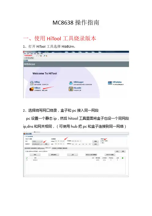
MC8638操作指南
一、使用HiTool工具烧录版本
1、打开HiTool工具选择HibBUrn,
2、选择烧写网口烧录,盒子和pc接入同一网段
pc设置一个静态ip,然后hitool工具里面将盒子也设一个同网段ip,dns和网关相同,(可使用hub把pc和盒子连接到同一网络)
3、配置COM信息
4、配置TFTP服务器,Hitool自带的TFTP工具烧录老是不成功,使用其他的TFTP就能解决,打开思科TFTP点查看选项配置TF TP路径
5、选择emmc烧写,选择emmc分区表文件
Hi3798MV100-emmc.xml ;选择勾选的文件,有文件的都勾选上,没有的不要勾选;选择好后,点击烧写,将盒子手动断电重启,开始烧录(提示端口69被占用请无视)。
6、烧写完成后需要烧录MAC和STBID,通过Hitool工具单独烧录下STBID分区烧写结束通过串口SecureCRTPortable写入MAC和STBID;
例如:
write_mac 00:19:F0:E1:B6:49
write_sn 0000040000010010006E0019F0E1B649
二、使用u 盘烧录版本;
1、盒子与pc 串口连接,打开串口工具,盒子开机过程中按ctrl+C 进入fastboot ,输入命令mmc erase 0 0 2 ,擦除数据;
2、把版本文件夹内update.zip,fastboot.bin,bootargs.bin,recovery.img, 4个文件拷贝到U盘根目录,盒子插上U盘然后断电重启自动完成烧录;
三、烧写sn号和mac,
1、盒子与pc串口连接;
2、打开HiProInfo工具,输入mac和id,点击确定,重启完成烧写
3、。

MC8638操作指南
一、使用HiTool工具烧录版本
1、打开HiTool工具选择HibBUrn,
2、选择烧写网口烧录,盒子和pc接入同一网段
pc设置一个静态ip,然后hitool工具里面将盒子也设一个同网段ip,dns和网关相同,(可使用hub把pc和盒子连接到同一网络)
3、配置COM信息
4、配置TFTP服务器,Hitool自带的TFTP工具烧录老是不成功,使用其他的TFTP就能解决,打开思科TFTP点查看选项配置TF TP路径
5、选择emmc烧写,选择emmc分区表文件
Hi3798MV100-emmc.xml;选择勾选的文件,有文件的都勾选上,没有的不要勾选;选择好后,点击烧写,将盒子手动断电重启,开始烧录(提示端口69被占用请无视)。
6、烧写完成后需要烧录MAC和STBID,通过Hitool工具单独烧录下STBID分区烧写结束通过串口SecureCRTPortable写入MAC和STBID;
例如:
write_mac00:19:F0:E1:B6:49
write_sn0000040000010010006E0019F0E1B649
二、使用u盘烧录版本;
1、盒子与pc串口连接,打开串口工具,盒子开机过程中按ctrl+C进入fastboot,输入命令mmc erase002,擦除数据;
2、把版本文件夹内update.zip,fastboot.bin,bootargs.bin,recovery.img, 4个文件拷贝到U盘根目录,盒子插上U盘然后断电重启自动完成烧录;
三、烧写sn号和mac,
1、盒子与pc串口连接;
2、打开HiProInfo工具,输入mac和id,点击确定,重启完成烧写
3、。

Product DescriptionThe ergonomically designed imager houses the imaging optics, detector, drive electronics, optical modulator,laser pointer and four standard or rechargeable AA size batteries. The system includes an optional pistol grip handle which holds virtually any ‘Pocket PC’or compatible ‘Palm’device as a combined processing, display unit and image storage device. As an alternative, the output of the imager can be displayed and processed in real time using a PC.OperationThe system is designed for either one or two handed operation. For one handed operation both the imager and the user provided ‘Pocket PC’/ ‘Palm’device can be attached to the handle to form a single integrated lightweight unit. For two handed operation the imager can be quickly detached from the handle leaving the ‘Pocket PC’/ ‘Palm’device attached for ease of operation. This latter configuration enables the imager to be pointed at awkward angles or used in confined places. Alternatively, instead of using a ‘Pocket PC’/ ‘Palm’device the imager can be linked to a PC or laptop computer using the RS232 serial cable supplied.Dec 2004IPU 40055 issue 3IRI 1011Universal Thermal ImagerThe IRI 1011 is a groundbreaking thermal imager product which brings the benefits of this versatile technology to the professional, the trades person and the non-specialist alike.The flexibility, ease of use and above all, the low cost of this product extend the normal application areas for thermal imaging from military and professional use, to wider use in industrial,commercial and domestic applications .Typical applications for the IRI 1011 include:Predictive and Preventative MaintenanceProcess MonitoringResearch and Development HV AC Troubleshooting Vehicle MaintenanceGeneral Industrial/Domestic......ABDWorld Leaders inArray-Based DetectorsThe IRI 1011 Universal Thermal ImagerPERFORMANCETemperature Measurement range:-10˚C to +300˚C Field of view (FOV):20˚x 20˚Spectral Response:8 to 14 micrometers Sensitivity:~0.3K @ 30˚C Displayed Image:96 x 96 pixels Detector:16 x 16 pixel array Frame rate:8HzIMAGE STORAGEUp to 1000 images per MB of SER POINTERA built in Class II laser is supplied to highlight the reference pixel.IMAGER POWER SUPPLYBattery:4 x AA type removable batteries.Lithium cells are recommended for operation at low temperatures.Operation time:Up to 8 hours.AC operation:AC adaptor, supplied.MECHANICALHousing: Impact Resistant Plastic.Dimensions: 120mm x 125mm x 80mm.Weight:< 600g not including ‘Pocket PC’/‘Palm’device and handle.Mounting: Handheld & Tripod mounting.IRI 1011 INCLUDESImager, software for ‘Pocket PC’, ‘Palm’& PC, 2m RS232 connection cable - imager to PC, user manual, AC power supply, carrying case.OPTIONA pistol grip handle for attaching imager and ‘Pocket PC’/ ‘Palm’Device for single handed operation.SPECIFICATIONABDWorld Leaders inArray-Based DetectorsInfraRed Integrated Systems Ltd, Towcester Mill,Towcester, Northants, NN12 6AD, UK Telephone:+44 (0) 1327 357824Fax:+44 (0) 1327 357825e-mail:***************.uk web site:Whilst IRISYS endeavour to ensure that all descriptions, weights, temperatures, dimensions and other statistics contained in this product information are correct, they are intended to give a general idea of the product only and IRISYS do not warrant their accuracy or accept liability for any reliance on them. IRISYS have a policy of continuous product improvement and reserve the right to change the specification of the products and descriptions in this data sheet. Prior to ordering products please check with IRISYS for current specification details. This product is protected by patents EP 0 853 237 B1 and US 6,239,433 B1. Other patents pending.All brands and product names are acknowledged and may be trademarks or registered trademarks of their respective holders.ENVIRONMENT Temp. operating range:-5˚C to +50˚C Humidity:10% to 90% non condensing Temp. storage range:-20˚C to +80˚CCE Mark (Europe):Complies with EMC directiveSETTINGS AND CONTROLS:User selectable sensitivity er selectable offset control (range).Auto adjust sensitivity/range.Display palettes: red/blue, green/blue and greyscale.‘Pocket PC’/ ‘Palm’device: two moveable temperature measurement cursors.PC: up to ten moveable temperature measurement cursors.User selectable emissivity values.User selectable image integration: 1 to 10 frames.Readout in ˚C, ˚F and K.Image snapshot.Image label.FEATURES - ‘POCKET PC’/ ‘PALM’SOFTWAREReal time image and temperature measurement display Multiple image storage and retrieval.Image browser.Battery Charge indicator‘Pocket PC’/ ‘Palm’device controlled by navigator button and touch sensitive screen controls. Reflected ambient temperature compensation.Temperature difference measurement.FEATURES - PC SOFTWAREMultiple image storage and retrieval.Time / Temperature display for up to ten user defined pixels.Save all 256 temperature values to Microsoft Excel.Copy & Paste images into other Microsoft applications.Reflected ambient temperature compensation.Real time image and temperature measurement displayCOMPUTER REQUIREMENTSPocket PC: Compatible with most ‘Pocket PC’devices running Microsoft ‘Pocket PC’2000, 2002 and 2003. e.g. HP iPAQ 2210, O2 XDA - (See IRISYS website for compatible Pocket PC’s). RS 232 to ‘Pocket PC’communication cable or CompactFlash RS 232 adaptor where applicable.Palm :Palm devices conforming to OS5 or higher, double density screen, 320 x 320 display resolution.eg. Palm Zire 71, Palm Tungsten T3. (See IRISYS website for compatible Palms)PC :IBM compatible PC with a minimum of:300MHz processor, MS Windows 2000 and XP (see IRISYS website for current list of operating systems supported). RS 232 serial port (115k Baud),16 bit colour graphics capability.........................CAUTIONCLASS II LASER PRODUCT635nm 0.9mW。
通导测试测试失败元件测试失败(元件错误)高压测试失败(高压错误)瞬间断电测试 时好时坏好线材移开产品,准备下一个测试第三章 测试机硬体介绍1.110V/230V 电源开关1500VDC 1000VAC2.如何安装治具板A.打开卡锁,取下盖子卡锁关闭状态 卡锁打开状态B.插入治具板,再将盖子盖上3.接口位置及名称NG OKNG OKOKNG NGOK主电源开关1500 V Touch 11000V Touch 1第六章创建、编辑测试线材资料1:如何进入编辑画面A.Main Menu 画面,按Test SetupB.在Test Setup 画面,按View & ChangeC.编辑线材资料画面如下2:如何编辑治具板2-1如何在线材表中增加一个治具板A.在View/Change Wirelist 画面,按ADP,再按CHANGE ADPB.在Change Adapters 画面,按ADDC.在Add Adapter Position 画面,使用“▲”“▼”选择治具板位置,然后按AddD.在Add Adapter 画面,使用“▲”“▼”选择之治具板编号,再按AddE.在 Change Adapter 画面,显示新的治具板2-2 如何从线材表中删除治具板A.在View/Change Wirelist 画面,按ADP,再按CHANGE ADPB.在Change Adapters 画面,使用“▲”“▼”选择之治具板编号,再按DELETE ,然后按OK 3:编辑低压参数设定3-1编辑低压导通阻值软驱打印机接口输入输出接口探针插口显示器接口网络接口键盘接口串行口1,2软驱键盘接口探针接口输入输出接口串行口打印机接口低压导通阻值编辑范围:0.1ohm – 100 K ohm (±1%±0.1ohm 1500V)(±4%±0.1ohm 1000V)500 K ohm, 1M, 5M, (±10% 1500V)(±20% 1000V)限定:当测试元件时,低压通导阻值不能大于100K ohms操作如下:A.在View/ Change Learn Settings 画面,触摸LV键,然后触摸CHANGE LV键,进入CHANGE LOW VOLTAGE画面:B.在CHANGE LOW VOLTAGE画面,触摸通导阻抗,进入ENTER CONNECTIONRESISTANCE画面。
HIOS 电动螺丝刀使用说明书 VZ 系列系列构成使用电压 AC 220V(2018年4月現在)制造商 株式会社HIOS 总公司 邮编270-2223 日本国千叶县松户市秋山1-16-5TEL :81-47-392-2001 F AX :81-47-392-7778VZ-1812、 VZ-1812PS 小系列 VZ-3007、 VZ-3007PS 小系列 VZ-4504、 VZ-4504PS 小系列使用说明书NO.ET-A024●为了使您掌握所选机种的使用方法及安全操作,请务必阅读随机附上的使用说明书,正确使用本产品。
●本安全操作注意规程属于一般安全性方面的说明书。
为安全使用请仔细阅读有关内容。
●请绝对不要在指定用途以外使用电动螺丝刀及变压器。
●要时常整理、整顿作业现场的周围。
保持便于操作的生产作业环境。
●电动螺丝刀等电动工具要避免阳光直射。
●所使用的电压必须符合电动螺丝刀本体制造标牌上所指定的电压额定值。
●如果使用指定以外的电压的话机体将会发生故障诱发触电事故。
有关作业现场的注意事项!注意 !警告 1.为安全使用●为了能安全使用本产品、请必须按照下面注意事项及警告使用产品。
●请不要以使用说明书指定以外的目的使用电动螺丝刀或变压器。
是引起故障或事故的原因。
●使用变压器时请必须设置防漏电跳闸和安全跳闸。
●请必须接上变压器以及HIOS 电动螺丝刀的接地线以确保安全。
●本产品为在220V 电压下使用的产品,切勿在其他电压条件下使用。
●本型号的电动螺丝刀为主机电源线一体型,任何部分如有异常,请不要自行拆开主机,而应立即停止使用并交给厂家或经销商修理。
●更换碳刷时,由于磨掉的碳粉致使绝缘效果降低,故请交给厂家或经销商进行维护检查。
一般每使用100万次或者每使用1年要做一次检查。
●请绝对避免与指定电压以外的电源进行连接。
万一发生触电事故或受伤等、本公司不承担责任。
●不要用湿手或带油的手操作电动螺丝刀。
是引起感电事故或受伤的原因。
hitool分区表
Hitool是一款硬盘分区工具,可以用来清除分区表、备份和还原分区表等操作。
以下是Hitool分区表的简要说明:清除分区表:选择需要清除分区表的硬盘,然后点击“清除分区表”菜单项,在弹出的对话框中选择需要清除的硬盘,并点击“确定”开始清除分区表。
完成后会弹出提示框,点击“确定”即可。
备份分区表:选择需要备份分区表的硬盘,然后按F2键或者单击菜单上的磁盘选项,单击备份分区选项。
在程序显示对话框后,选择一个备份文件的位置,输入文件名并单击【保存】。
当程序显示提示时,表示备份分区表成功。
还原分区表:选择需要还原分区表的磁盘,单击菜单【磁盘-还原分区】,按下键盘上的F3键也可以。
程序显示文件选择的弹窗,选择之前备份的分区备份表之后,在内存中程序会加载保存的分区表,并在主界面提示,以便用户确认分区表是否需要还原,防止出现错误。
先检查完毕软件界面显示的分区情况是否正确后,再确认分区表。
完成确认后,单击对话框中的【是】,根据情况选择是否同时还原分区引导扇区。
选择否只还原分区,选择【取消】则放弃还原,程序不会更改分区表和引导扇区。
以上是Hitool分区表的一些基本操作说明。
在使用Hitool进行硬盘分区操作时,请注意备份重要数据,以防数
据丢失。
同时,也需要注意操作步骤的正确性和安全性,避免误操作导致硬盘数据损坏或丢失。
hitool清除cm101s—2分区表随着计算机技术的不断发展,硬盘分区的管理也变得越来越重要。
在分区管理过程中,有时会遇到需要清除CM101S-2分区表的情况。
本文将介绍如何使用Hitool这款工具清除CM101S-2分区表,并提供一些实用技巧和注意事项。
一、清除CM101S-2分区表的必要性CM101S-2是一款常见的硬盘分区类型,它的分区表负责记录分区的起始地址、大小等信息。
当分区表出现错误时,可能会导致分区无法正常使用,甚至数据丢失。
因此,在遇到CM101S-2分区表错误时,清除分区表并进行重新分区是十分必要的。
二、Hitool清除CM101S-2分区表的操作步骤1.下载并安装Hitool这款分区管理工具。
在百度搜索框中输入“Hitool”,找到官方网站下载并安装。
2.打开Hitool,切换到“分区”选项卡。
在这里,您可以查看计算机上的所有分区,包括CM101S-2分区。
3.选中需要清除分区表的CM101S-2分区,点击“删除分区”按钮。
此时,Hitool会弹出一个警告框,提示您删除分区将导致数据丢失。
4.确认无误后,点击“确定”按钮。
Hitool会开始清除CM101S-2分区表。
完成后,该分区将变为未分配空间。
5.如果需要重新分区,可以在Hitool中选择“快速分区”或“自定义分区”。
在这里,您可以设置分区的起始地址、大小和文件系统等参数。
完成后,点击“应用”按钮,Hitool会将新的分区表写入硬盘。
三、注意事项和实用技巧1.在清除CM101S-2分区表之前,请务必备份重要数据。
由于清除分区表可能导致数据丢失,为确保数据安全,请提前做好备份。
2.如果您对分区操作不熟悉,请务必寻求专业人士的帮助。
分区操作涉及到硬盘数据的重新分配,一旦操作失误,可能导致数据丢失或硬盘损坏。
3.在使用Hitool进行分区操作时,请遵循操作提示。
如遇到问题,可以参考官方文档或在线搜索解决方案。
4.如果您需要在操作系统中进行分区操作,可以尝试使用磁盘管理工具。
hitool清除cm101s—2分区表
【原创实用版】
目录
1.概述:介绍 Hitool 工具及其功能
2.清除分区表:解释分区表的作用以及为何需要清除分区表
3.操作步骤:详细说明如何使用 Hitool 清除 CM101S-2 分区表
4.注意事项:在使用过程中需要注意的问题
正文
一、概述
Hitool 是一款功能强大的硬盘管理工具,它可以帮助用户对硬盘进行低级格式化、分区、修复等多种操作。
在使用硬盘时,分区表可能会受到损坏,导致硬盘无法正常使用。
此时,用户可以借助 Hitool 工具来清除分区表,从而恢复硬盘的正常使用。
二、清除分区表
分区表是硬盘中的一个重要区域,它记录了硬盘上所有分区的信息。
当分区表受到损坏时,可能会导致硬盘无法识别分区,甚至无法启动系统。
在这种情况下,用户需要清除分区表,以便恢复硬盘的正常使用。
三、操作步骤
下面将详细介绍如何使用 Hitool 清除 CM101S-2 分区表:
1.首先,从官方网站下载并安装 Hitool 工具。
2.打开 Hitool,选择“硬盘分区”菜单,然后点击“清除分区表”。
3.在弹出的对话框中,选择需要清除分区表的硬盘,并点击“确定”。
4.Hitool 将开始清除分区表,完成后会弹出提示框,点击“确定”即可。
四、注意事项
在使用 Hitool 清除分区表时,需要注意以下几点:
1.在操作前,请确保已经备份好硬盘上的重要数据,以免意外丢失。
2.选择需要清除分区表的硬盘时,请务必谨慎,避免误操作导致数据丢失。
3.在清除分区表过程中,请勿关闭 Hitool 工具,以免操作失败。