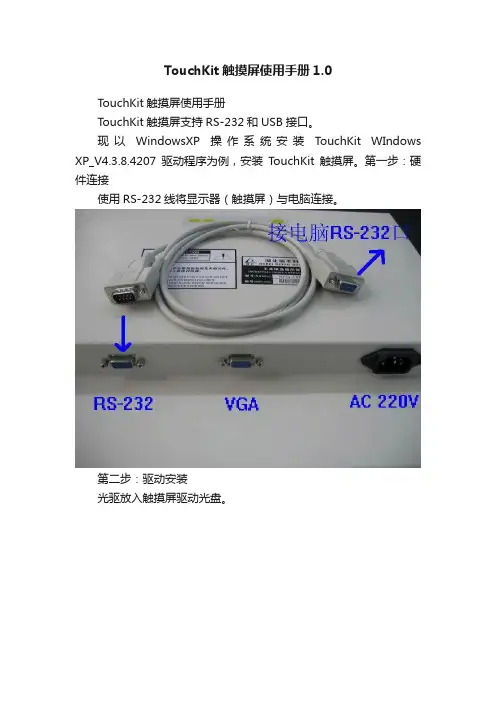
(整理)TouchKit四线产品规格书.
- 格式:doc
- 大小:192.00 KB
- 文档页数:13
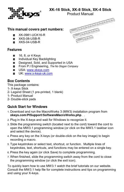
XK-16 Stick, XK-8 Stick, XK-4 StickProduct ManualThis manual covers part numbers:XK-0981-UCK16-RXKS-08-USB-RXKS-04-USB-RFeatures16, 8, or 4 KeysIndividual Key BacklightingDesigned, Sold, and Supported in USAFrom P.I Engineering, The No Slogan CompanyUSA: UK: Box ContentsThis package contains:1-X-keys Stick2-Legend Sheet (1 pre-printed, 1 blank)1-Product Manual2-Double-stick padsQuick Start for Windows1.Download and run the MacroWorks 3 (MW3) installation program from /PISupport/SoftwareMacroWorks.php. .2.Plug in the X-keys and wait for Windows to recognize it.3.Slide the programming switch (located next to the cord) toward the cord to open the MW3.1 programming window (or click on the MW3.1 taskbar icon and select the device).4.Press any key on the X-keys (or double-click on the key image) to begin recording a macro.5.Type keystrokes or select text, shortcut, or function. Multiple lines of keystrokes, text, shortcuts, and functions may be entered on a single key.6.Press the key again (or click Save) to complete programming.7.When finished, slide the programming switch away from the cord to close the programming window (or click the exit icon).To quickly learn how to use MW3.1 watch the brief tutorials on our website. Consult the MW3.1 help file for complete instructions and tips on programming and using your X-keys.DevelopersP.I. Engineering offers a free Software Development Kit with code samples inC#, C++ and .NET. We also offer a Linux SDK and Android code samples. Please visit the Developers section on our website:/PISupport/Developer.phpSupportShould you encounter difficulty with the installation or programming, please open the MW3 or ControllerMate Help File. You may also contact technical support.USA: ************** | Phone: 1-517-655-5523UK: ****************************.uk | Tel +44 (0)20 3474 0234CompatibilityX-keys USB devices require MacroWorks 3 for Windows XP, Vista, or 7 or ControllerMate for Mac OS X. The X-keys Stick also has a “Hardware Mode”which gives it the ability to mimic a USB keyboard or mouse on any USB enabled operating system (including Linux). Learn more about Hardware Mode on our web site or contact our Technical Support Department(**************).Identifying the KeysSelect legends from the pre-printed sheet or use the blank legend sheet to create your own key legends. The keycap lenses snap off with a fingernail or small screwdriver. Place the legend inside the lens, and replace it. The key caps hold a legend 0.575" wide and 0.5" high (14.6mm x 12.7mm). Other options are available for printing legends for multiple units. Contact our Sales Department(***************)formoreinformation.Compatible AccessoriesPlease visit the Accessories page on our website for details on the following.X-keys USB Extender – up to 150 feet via CAT 5 cableReplacement keycapsUSB powered lamp for studio or performance applicationsOther Products from P.I. EngineeringX-keys XK-24 – 24 keys with backlightingX-keys XK-60/XK-80 – 60 or 80 programmable keysX-keys XKE-128 – 128 programmable keysX-keys XKE-124 T-bar – 124 keys with a T-bar faderX-keys XK-12 Joystick – 12 keys with a precision joystickX-keys XK-12 Jog & Shuttle – 12 keys with jog & shuttleX-keys XK-3 Foot Pedal – three programmable pedalsX-keys XK-68 Joystick - 68 keys with a precision joystickX-keys XK-68 Jog & Shuttle – 68 keys with jog & shuttleX-keys USB 12 Switch Interface – 12 switch portsX-keys Encoder Board – 128 switch pointsFCC Declaration of ConformityThis equipment has been tested and found to complywith the limits for a Class B digital device, pursuant topart 15 of the FCC rules. These limits are designed toprovide reasonable protection against harmfulinterference when the equipment is operated in a residential installation. This equipment generates, uses, and can radiate radio frequency energy and if not installed and used in accordance with the instruction manual may cause harmful interference to radio communications. However, there is no guarantee that interference will not occur in a particular installation. If this equipment does cause harmful interference to radio or television reception, which can be determined by turning the equipment off and on, the user is encouraged to try to correct the interference by one or more of the following measures:•Reorient or relocate the receiving antenna.•Increase the separation between the equipment and the receiver.•Connect the equipment into an outlet on a circuit different from that to which the receiver is connected.•Consult the dealer or an experienced radio TV technician for help.Any changes or modifications not expressly approved by the manufacturer could void the user’s authority to operate the equipment.CE Declaration of ConformityWe, P.I. Engineering, Inc., declare that the X-keys is in conformance with:•EMC Directive 2014/30/EU, tested in accordance with EN 55032:2012 and 55024:2010/A1:2015•Certificate of compliance on file at P.I. Engineering, 101 Innovation Pkwy, Williamston, MI 48895Contact UsUSA Sales*********************** Phone: 1-517-655-5523 USA Technical Support**********************Phone: 1- 517-655-5523/support.phpUSA Shipping AddressP.I. Engineering101 Innovation ParkwayWilliamston, MI 48895-1663UK Sales****************************.uk Tel +44(0)20 3474 0234UK Technical Support****************************.ukTel +44(0)20 3474 0234UK Shipping AddressKeyboard Specialists LtdUnit 44-45, SalisburyStreet Darlaston WestMidlands WS10 8XBUnited KingdomLimited WarrantyFor all X-keys products purchased and installed in the United States, Canada and the United Kingdom, P.I. Engineering warrants that the X-keys product will be free from defects in materials and workmanship under normal use and service, and will meet the specifications presented by P.I. Engineering at the time of original purchase, for one year as evidenced by a copy of the purchase receipt. Under this warranty, P.I. Engineering will, at its sole option, repair or replace any X-keys product which is defective, provided that you are responsible for (i) the cost of transportation of the product to P.I. Engineering or its designated service facility, and (ii) any loss or damage to the product resulting from such transportation.Upon discovery of a defect in the product within the Warranty Period, you should notifyP.I. Engineering Technical Support to obtain an RMA (return authorization number) and instructions for shipping the product to a service location designated by P.I. Engineering. You should send the product, shipping charges prepaid, to the designated location, accompanied by the return authorization number, your name, address, and telephone number, proof of purchase, and a description of the defect. P.I. Engineering will pay for return of product(s) to the customer. P.I. Engineering shall have no responsibility to repair or replace the X-keys product if the failure has resulted from accident, abuse, mutilation, misuse, or repair/modification performed by any entity other than P.I. Engineering.THIS WARRANTY IS EXCLUSIVE OF ALL OTHER WARRANTIES, WHETHER EXPRESSED, IMPLIED, OR STATUTORY.P.I. ENGINEERING DOES NOT WARRANT THIS X-keys PRODUCT FOR FITNESS FOR A PARTICULAR PURPOSE OR MERCHANTABILITY. P.I. ENGINEERING AND ITS EMPLOYEES SHALL NOT BE HELD LIABLE FOR ANY CONSEQUENTIAL, INDIRECT, OR INCIDENTAL DAMAGES, EVEN IF ADVISED OF THEIR POSSIBILITY, ARISING OUT OF THE USE OR INABILITY TO USE THIS PRODUCT. SOME STATES DO NOT ALLOW FOR THE EXCLUSION OR LIMITATION OF CERTAIN LIABILITIES, SO THE ABOVE LIMITATIONS MAY NOT APPLY TO YOU. THIS WARRANTY GIVES YOU SPECIFIC LEGAL RIGHTS, AND YOU MAY ALSO HAVE OTHER LEGAL RIGHTS WHICH VARY FROM STATE TO STATE.In the event that the above limitations are held unenforceable, P.I. Engineering’s liability for any damages to you or to any party shall not exceed the purchase price you paid, regardless of the form of any claim.This limited warranty is valid for and only applies to products purchased and used inside the United States (and its territories), Canada, and the United Kingdom.This limited warranty is governed by the laws of the United States of America and the state of Michigan.X-keys Electronic design: P.I. Engineering, Inc., Patent # 4964075© 2019P.I. Engineering, Inc. All rights reserved.Y-mouse, Y-see two, Y-key key, X-keys, and the “P.I. Eclipse” are trademarks of P.I. Engineering, Inc.PS/2 is a registered trademark of International Business Machines, Inc.All other trademarks are property of their respective owners.USA: ◘ UK:PI Part#0987。
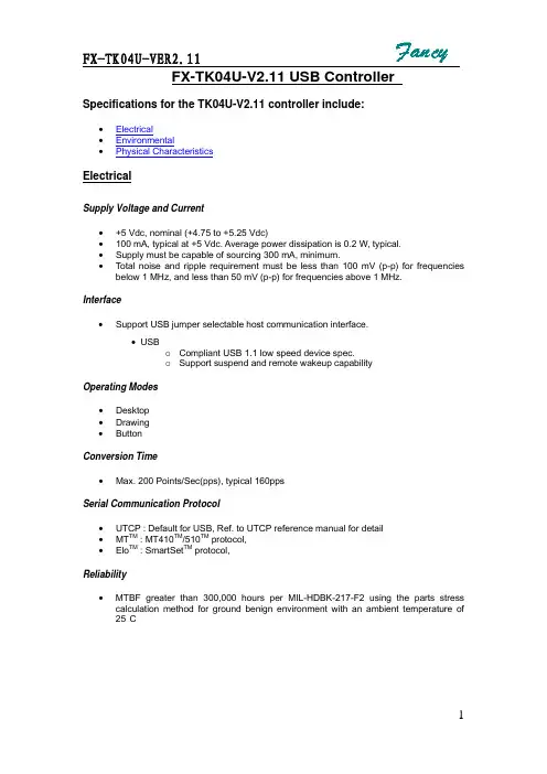
FX-TK04U-V2.11 USB Controller Specifications for the TK04U-V2.11 controller include:•Electrical•Environmental•Physical CharacteristicsElectricalSupply Voltage and Current•+5 Vdc, nominal (+4.75 to +5.25 Vdc)•100 mA, typical at +5 Vdc. Average power dissipation is 0.2 W, typical.•Supply must be capable of sourcing 300 mA, minimum.•Total noise and ripple requirement must be less than 100 mV (p-p) for frequencies below 1 MHz, and less than 50 mV (p-p) for frequencies above 1 MHz.Interface•Support USB jumper selectable host communication interface.• USBo Compliant USB 1.1 low speed device spec.o Support suspend and remote wakeup capabilityOperating Modes• Desktop• Drawing• ButtonConversion Time•Max. 200 Points/Sec(pps), typical 160ppsSerial Communication Protocol•UTCP : Default for USB, Ref. to UTCP reference manual for detail• MT TM : MT410TM/510TM protocol,• Elo TM : SmartSet TM protocol,Reliability•MTBF greater than 300,000 hours per MIL-HDBK-217-F2 using the parts stress calculation method for ground benign environment with an ambient temperature of 25°CEnvironmentalTemperature•Operating: 0°C to 65°C•Storage: -25°C to 85°CHumidity•Operating: 10% to 90% RH, non-condensing•Storage: 10% to 90% RH, non-condensingShock and Vibration•Three axis sine wave, 50 Hz to 2kHz, 1 G, 2 minutes/Octave with dwell on resonances ESD•Per EN 6100-4-2 1995: Level 4. Contact discharge 8kV, air discharge 15kV. Flammability•The printed circuit board substrate is rated 94V0. All plastic components, such as headers and connectors, are also rated 94V0.Physical CharacteristicsConstruction()•Four-layer surface-mount design with internal ground plane for EMI suppression.Dimension•Total Width: 20 mm•Total Length:50 mm(including connectors)• Total height:4.0mm•All mounting holes are plated through for chassis ground connection. Refer to the drawings at the end of this document.Connectors and Pin Definitions• The connector configuration permits the controller to be placed in-line between thetouchscreen and serial I/O attachments. The USB connector , J1, is a single row by seven-position header with pins spaced on1mm centers. Refer to the following figure for pin number locations.Figure 1. Pin diagram for serial connector, J1, as viewed from connector matingsurfaces Signal definition for USB interface(J1/J3)Signal Name J1(J3) pinSignal FunctionPower (V5IN) 1 +5V power drain from host USB portD- 2 USB bus signalD+ 3 USB bus signalGND 4 signal groundGND 5 signal groundTable 1. Host Connector, J1, signal names and functionsTouch screen connector , J2 signal descriptionsThe touch screen connector, J2, is a dual row by five-position header with0.025-inch square pins spaced on 0.100 centers. 4W sensor must beconnected to the low row of the connector.The 4 Wire Touchscreen connector, J2 lower row, and signal descriptionsTable 2. Touchscreen connector, J2 lower row, pins and signal namesSignal nameJ2 pin Signal function Y+1 Connect to 4 Wire touchscreen Y+ X+2 Connect to 4 Wire touchscreen X+ Y-3 Connect to4 Wire touchscreen Y- X- 4 Connect to 4 Wire touchscreen X-。

N S2016用户手册V1.0深圳市纳芯威科技有限公司2009年7月目录1 功能说明 (4)2 主要特性 (4)3 应用领域 (4)4 典型应用电路 (4)5 极限参数 (5)5.1 电气特性 (6)6 芯片管脚描述 (8)6.1 管脚分配图 (8)6.2 引脚功能描述 (8)7 NS2016典型参考特性 (9)8 工作原理 (11)8.1 基本原理描述 (11)8.2 模拟输入特性 (11)8.3 内部参考电压 (12)8.4 单端工作模式 (12)8.5 差分工作模式 (13)8.6 触摸屏应用建议 (13)8.7 温度测量 (14)8.8 电池电压测量 (15)8.9 压力测量 (15)9 数字接口 (16)9.1 写命令 (16)9.2 读命令 (17)9.3 高速模式 (18)9.4 数字时序 (18)9.5 数据格式 (20)9.6 笔中断输出 (20)10 应用注意事项 (21)11 芯片封装物理尺寸 (22)11.1 TSSOP-16封装 (22)图目录图1 NS2016典型应用电路 (4)图2 TSSOP-16封装管脚分配图 (8)图3 NS2016模拟输入简图 (11)图4 内部电压源示意图 (12)图5 单端模式工作示意图(C3=0,Y方向驱动开关闭合,XP作为模拟输入) (13)图6 差分参考源工作模式简图(C3=1,Y方向驱动开关闭合,XP作为模拟输入) (13)图7 温度测量功能示意图 (14)图8 电池电压测量功能模块图 (15)图9 压力测量模块图 (16)图10 I2C接口写命令时序图 (16)图11 I2C接口读命令时序图 (17)图12 NS2016数字接口时序图 (18)图13 理想情况输入电压和输出编码对应关系 (20)图14 PENIRQ功能模块图 (20)图15 TSSOP-16封装尺寸 (22)表目录表1 芯片极限参数表 (5)表2 NS2016电气特性表 (6)表3 ADC输入信号配置 (11)表4 地址字节 (16)表5 命令字节 (17)表6 PD1、PD0控制位 (17)表7 时序规范说明 (18)1功能说明NS2016是一款4线制电阻式触摸屏控制器,内含12位分辨率A/D转换器。
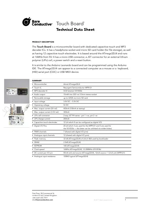
PRODUCT DESCRIPTIONT he Touch Board is a microcontroller board with dedicated capacitive touch and MP3 decoder ICs. It has a headphone socket and micro SD card holder (for file storage), as well as having 12 capacitive touch electrodes. It is based around the ATmega32U4 and runsat 16MHz from 5V. It has a micro USB connector, a JST connector for an external lithium polymer (LiPo) cell, a power switch and a reset button.It is similar to the Arduino Leonardo board and can be programmed using the Arduino IDE. The ATmega32U4 can appear to a connected computer as a mouse or a keyboard,(HID) serial port (CDC) or USB MIDI device.SUMMARY• M icrocontroller Atmel ATmega32U4• Touch IC Resurgent Semiconductor MPR121• MP3 decoder IC VLSI Solution VS1053b• Audio output 15mW into 32Ω via 3.5mm stereo socket• Removable storage up to 32GB via micro SD card• Input voltage 3.0V DC – 5.5V DC• Operating voltage 5V DC• Max. output current (5V rail) 400mA (100mA at startup)• Max. output current (3.3V rail) 300mA• LiPo cell connector 2-way JST PH series - pin 1 +ve, pin 2 -ve• LiPo charge current 200mA• Capacitive touch electrodes 12 (of which 8 can be configured as digital I/O)• Digital I/O Pins 20 (of which 3 are used for the MPR121 and 5 are used forthe VS1053b — the latter can be unlinked via solder blobs)• PWM channels 7 (shared with digital I/O pins)• Analogue input channels 12 (shared with digital I/O pins)• Flash memory 32 kB (ATmega32U4) of which 4kB used by bootloader• SRAM 2.5kB (ATmega32U4)• EEPROM 1kB (ATmega32U4)• Clock speed 16MHz (ATmega32U4), 12.288MHz (VS1053b)• DC current per I/O pin 40mA sink and source (ATmega32U4), 12mA source / 1.2mA sink (MPR121)• Analogue input resistance 100MΩ typical (ATmega32U4)Technical Data SheetTouch Board®POWERThe Touch Board can be powered via the micro USB connection or from a 3.7V lithium polymer (LiPo) cell connected to the 2-way JST PH series connector. The power switch will switch the board on or off when powered by either power source. If power is supplied over USB whilst the LiPo cell is connected, then the charge LED will illuminate and the LiPo will charge from USB power, regardless of power switch position. INPUT AND OUTPUTThe Touch Board has the same I/O layout as the Arduino Leonardo, with two important differences. Firstly, some of the Leonardo pins are used to drive the MPR121, VS1053b and micro SD card. If you want to use these pins in your project, you can disconnect them from the components they are connected to by removing the appropriate solder blobs on the board. However, if you do this, you will not be able to use the functionality provided by the components the pins were connected to, unless you re-make the blobs. Please reference the Touch Board Pin Map and Touch Board and Shields Guide documents for more information.Secondly, there are 12 capacitive touch electrodes, brought out to contacts along the top edge, which afford connecting through painting, alligator clips or M3 hardware, and a row of 0.1" / 2.54mm pitch pads on the right side, for you to solder a header to if you wish. 8 of these can be used as digital I/O.Each special pin function is explained below.• Touch electrodes These connect to the MPR121 and provide capacitive touch / proximityE0-E11 sensing. E4-E11 can optionally be used as 3.3V digital inputs or outputs.• Serial Used to receive (RX) and transmit (TX) TTL serial data using the ATmega32U4 Pins 0 (RX) and 1 (TX) UART. This is separate to the USB serial (CDC) functionality, so the boardeffectively has two serial ports — one virtual over USB and one physical.• TWI (I2C) TWI (I2C) data and clock pins — these are used to communicateP ins 2 (SDA) and 3 (SCL) with the MPR121.• IRQ This pin is used to detect interrupt events from the MPR121 —Pin 4 it should only be configured as an input.• SD-CS This pin is used to select the micro SD card on the SPI bus. You can disconnect Pin 5 i t from the micro SD card pin for your own use by removing the solder blobadjacent to the output pad.• D-CS This pin is used to select the data input on the VS1053b. You can disconnectPin 6 i t from the VS1053b pin for your own use by removing the solder blob adjacent tothe output pad.• DREQ This pin is used to detect data request events from the VS1053b.Pin 7 Y ou can disconnect it from the VS1053b pin for your own use by removing thesolder blob adjacent to the output pad.• MP3-RST This pin is used to reset the VS1053b. You can disconnect it from the VS1053b Pin 8 pin for your own use by removing the solder blob adjacent to the output pad.• MP3-CS This pin is use to select the instruction input on the VS1053b. You can disconnect Pin 9 i t from the VS1053b pin for your own use by removing the solder blob adjacent tothe output pad.• MIDI IN This pin can be used to pass MIDI data to the VS1053b and have it behavePin 10 a s a MIDI synthesiser as opposed to an MP3 player. By default, this is notconnected, but you can complete the connection to pin 10 by placing a solderblob across the pair of rectangular pads provided adjacent to the output pad.You will also need to place a solder blob on the “MIDI on” pad pair abovethe ICSP header.• HEADPHONE OUTPUT These pins provide the headphone output from the VS1053b on 0.1" / 2.54mm AGND, R, L p itch pads that you can solder a pin header to if you wish, as an alternativeto the 3.5mm socket.• EXTERNAL INTERRUPTS These pins can be configured to trigger an interrupt on a low value, a risingPins 0, 1, 2, 3, 7 or falling edge, or a change in value.Continued on next page.• PWM Provide 8-bit PWM output.Pins 3, 5, 6, 9, 10, 11, and 13• SPI Note that the SPI pins are not connected to any of the digital I/O pins as they are O n the ICSP header o n the Arduino Uno. This means that if you have a shield that uses SPI, but doesNOT have a 6-pin ICSP connector that connects to the Touch Board’s 6-pin ICSPheader, the shield will not work.• LED There is a built-in LED connected to digital pin 13. When the pin is HIGH value, Pin 13 t he LED is on, when the pin is LOW, it is off.• ANALOGUE INPUTS Provide 10-bit ADC input, returning integers from 0-1023. All analog pins haveA0-A5, A6-A11 (in addition) the same functionality as general purpose input / output (GP10) pins.A6 – A11 are on digital pins 4, 6, 8, 9, 10, and 12 respectively.• AREF Optional reference voltage for the analog inputs.• RESET Bring this line LOW to reset the ATmega32U4.OVERCURRENT PROTECTIONThe Touch Board has overcurrent protection for both the USB and battery power inputs. This protects them from trying to source too much current, which may damage them or the board. This protectionis provided by two positive temperature coefficient (PTC) resettable fuses. The USB fuse has a holding current of 500mA and a trip current of 1000mA. The LiPo fuse has a holding current of 1100mA and a trip current of 2200mA. If these fuses trip, you will notice that the board loses power. You should switch off the board, and inspect it for faults, correcting any you find. After 20 seconds the fuses should reset and you can plug the board back in again.PHYSICAL CHARACTERISTICS / PROGRAMMINGThe Touch Board can be programmed using the Arduino IDE. More details on how to do this can be found at /touch-board/。
iPod touch使用手册适用于 iPhone OS 3.0 软件目录7 第 1 章:使用入门7 已为 iPod touch 优化的使用手册7 必备项目8 注册 iPod touch8 同步12 邮件、通讯录和日历帐户14 安装配置描述文件15 断开 iPod touch 与电脑的连接16 第 2 章:基本功能16 iPod touch 概览18 主屏幕21 按钮22 触摸屏25 屏幕键盘29 搜索30 Bluetooth 耳机31 连接到 Internet31 电池33 安全功能33 清洁 iPod touch34 重新启动 iPod touch 和将它复位35 第 3 章: Safari35 浏览网页38 搜索 Web38 书签39 Web Clip40 第 4 章:音乐和视频40 获得音乐、视频以及更多42 音乐和其他音频49 视频251 设定睡眠计时器51 更改浏览按钮53 第 5 章: App Store53 关于 App Store53 浏览和搜索55 简介屏幕56 下载应用程序56 删除应用程序57 撰写评论57 更新应用程序58 同步购买的应用程序59 第 6 章: Mail59 设置电子邮件帐户59 发送电子邮件60 检查和阅读电子邮件63 搜索电子邮件64 整理电子邮件65 第 7 章:日历65 关于日历65 同步日历65 查看日历66 搜索日历67 订阅日历67 将日历事件添加到 iPod touch68 对会议邀请作出回应69 提醒70 第 8 章:照片70 关于照片70 与电脑同步照片70 查看照片72 幻灯片显示72 共享照片74 将照片指定给联系人74 墙纸75 第 9 章:通讯录75 添加联系人76 搜索联系人76 管理 iPod touch 上的联系人目录377 第 10 章: YouTube77 查找及观看视频78 控制视频回放79 管理视频79 获取更多信息80 使用 YouTube 帐户功能81 更改浏览按钮82 第 11 章:股市82 查看股票报价83 获取更多信息84 第 12 章:地图84 查找及查看位置88 给位置制作书签88 获得路线90 显示交通状况90 查找并联系商业机构92 第 13 章:天气92 查看天气摘要93 获得更多天气信息94 第 14 章:语音备忘录94 录制语音备忘录95 听语音备忘录95 管理语音备忘录96 修剪语音备忘录97 共享语音备忘录97 同步语音备忘录98 第 15 章:备忘录98 编写和阅读备忘录98 搜索备忘录99 以电子邮件方式发送备忘录99 同步备忘录100 第 16 章:时钟100 世界时钟100 闹钟101 秒表101 计时器4 目录102 第 17 章:计算器102 使用计算器102 标准内存函数103 科学计算器按键105 第 18 章:设置105 Wi-Fi106 VPN106 通知106 亮度106 通用112 音乐112 视频113 照片113 Store113 邮件、通讯录和日历117 Safari118 Nike + iPod119 第 19 章: iTunes Store119 关于 iTunes Store120 查找音乐、视频以及更多内容121 购买音乐或有声读物121 购买或租借视频122 流化或下载 Podcast122 检查下载状态123 同步已购买的内容123 更改浏览按钮124 查看帐户信息124 验证购买的内容125 第 20 章: Nike + iPod125 激活 Nike + iPod126 附加的 Nike + iPod 设置127 附录 A :故障诊断127 Apple iPod touch 支持网站127 通用128 iTunes 和同步129 声音、音乐和视频130 iTunes Stores131 Safari、Mail 和“通讯录”133 备份 iPod touch目录5134 更新和恢复 iPod touch 软件135 iPod touch 辅助功能136 附录 B :其他资源136 安全、软件和服务信息137 已为 iPod touch 优化的使用手册137 处理和回收信息138 Apple 和环境6 目录7·【警告】为避免受伤,请在使用 iPod touch 之前先阅读本手册中的所有操作说明和《iPod touch 重要产品信息指南》(网址为 /support/manuals/ipodtouch )中的安全信息。
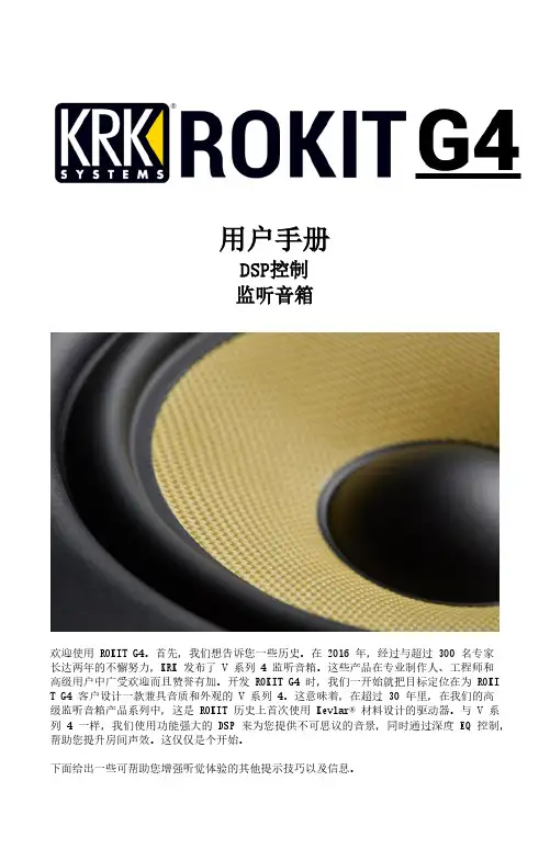
用户手册DSP控制监听音箱欢迎使用 ROKIT G4。
首先,我们想告诉您一些历史。
在 2016 年,经过与超过 300 名专家长达两年的不懈努力,KRK 发布了 V 系列 4 监听音箱。
这些产品在专业制作人、工程师和高级用户中广受欢迎而且赞誉有加。
开发 ROKIT G4 时,我们一开始就把目标定位在为 ROKI T G4 客户设计一款兼具音质和外观的 V 系列 4。
这意味着,在超过 30 年里,在我们的高级监听音箱产品系列中,这是 ROKIT 历史上首次使用Kevlar® 材料设计的驱动器。
与 V 系列 4 一样,我们使用功能强大的 DSP 来为您提供不可思议的音景,同时通过深度 EQ 控制,帮助您提升房间声效。
这仅仅是个开始。
下面给出一些可帮助您增强听觉体验的其他提示技巧以及信息。
房间布置和设置。
KRK 设计团队煞费苦心对成百上千个监视器布置和房间声学场景进行建模分析,以确保 KRK 提供最有用的 EQ 工具,同时尽量减少用户侧调试。
房间的设计和构造往往不完美,所以房间声学是当前工作室所面临的最大问题。
许多了不起的工作室都设在经过改造的房子里。
我们通过让您控制系统,从而避免这类情况导致的问题。
通过LOW EQ和HIGH EQ两个功能,系统提供 25 种不同的 EQ 和弦配置组合,帮助您调试工作室声学,实现更为准确的监听。
首先,将LOW EQ和HIGH EQ设置为3:FLAT,纯调,无减弱或增强,VOLUME 设置为 0.0dB。
根据以下说明和图表在您房间内进行设置。
听一些喜欢的歌曲和混音片段。
调试 EQ 前,在房间内尝试不同位置和不同布置,然后调试 EQ,获取最佳听觉和监听体验。
SYSTEM SETUP整体系统设置对于避免不必要的声互作用十分关键。
房间的自然音响效果可能由于异常阻尼或回声而导致在各种频率时改变声级。
有关更多细节,请遵守下面的检查表。
1.系统设定(监听音箱和工作台)必须置于房间的前三分之一内。
TouchWin使用手册Human Machine InterfaceTouchWin使用手册●安全注意事项●在设计系统时,请仔细阅读相关手册,同时要非常注意安全。
此外,实习时请特别注意以下几点,正确操作设备。
◎实习注意事项◎注意●请遵照讲师或说明书上的展开实习。
●请不要随意安装实习机的模块,改装接线。
否则会引起故障、误动作、损失、火灾。
●实习机发出异臭/弄音时,请关闭电源开关。
危险●通电时请不要接触端子,以免引起触电。
●请不要打开盖板。
TouchWin使用手册前言PLC(Programmable Logical Controller)通常称为可编程逻辑控制器,是一种以微处理器为基础,综合现代计算机技术、自动控制技术和通信发展起来的一种通用的工业自动控制装置,由于它拥有体积小、功能强、程序设计简单、维护方便等优点,特别是它适应恶劣工业环境的能力和它的高可靠性,使它的应用越来越广泛,已经被称为现代工业的三大支柱(即PLC、机器人和CAD/CAM)之一。
人机界面是在操作人员与机器设备之间作双向沟通的桥梁,用户可以自由的组合文字、按钮、图形、数字等来处理或监控管理及应付随时可能变化信息的多功能显示屏幕。
随着机械设备的飞速发展,以往的操作界面需要熟练的操作员才可以操作,而且操作困难,无法提高工作效率。
但是使用人机界面能够明确指示并告知操作员机器设备目前的状态,使操作变得简单生动,并且减少操作上的失误,即使是新手也可以很轻松地操作整个机器设备。
使用人机界面还可以使机器的配线标准化、简单化,同时也能减少PLC监控器所需的I/O点数,降低生产成本,同时由于面板控制的小型化及高性能,相对地提高了整个设备的附加价值。
TouchWin使用手册目录前言------------------------------------------------------------------------------------------------------4目录-----------------------------------------------------------------------------------------------------5硬件篇--------------------------------------------------------------------------------------------------71 产品概述------------------------------------------------------------------------------------------------------------71-1 功能------------------------------------------------------------------------------------------------------------8 1-2 一般规格------------------------------------------------------------------------------------------------------9 1-3 各部分名称--------------------------------------------------------------------------------------------------112 外形尺寸----------------------------------------------------------------------------------------------------------132-1 TP460-L尺寸-----------------------------------------------------------------------------------------------13 2-2 TP560-L/TP560-T尺寸------------------------------------------------------------------------------------133 安装方法----------------------------------------------------------------------------------------------------------14软件篇-------------------------------------------------------------------------------------------------151 关于作图软件----------------------------------------------------------------------------------------------------151-1 软件的安装-------------------------------------------------------------------------------------------------15 1-2 软件画面的构成-------------------------------------------------------------------------------------------162 入门须知----------------------------------------------------------------------------------------------------------192-1 新建工程----------------------------------------------------------------------------------------------------192-1-1 新建画面或窗口--------------------------------------------------------------------------------------21 2-2 画面或窗口标题的设定----------------------------------------------------------------------------------23 2-3 图形的制作-------------------------------------------------------------------------------------------------262-3-1 画直线、长方形、圆-------------------------------------------------------------------------------262-3-2 画多边形、折线--------------------------------------------------------------------------------------272-3-3 画圆弧--------------------------------------------------------------------------------------------------282-3-4 尺寸的变更--------------------------------------------------------------------------------------------282-3-5 选中对象的移动--------------------------------------------------------------------------------------292-3-6 选中对象的剪切、复制和粘贴-------------------------------------------------------------------30 3部件----------------------------------------------------------------------------------------------------------------31 3-1 文字串设置-------------------------------------------------------------------------------------------------31 3-2 动态文字串-------------------------------------------------------------------------------------------------33 3-3 指示灯-------------------------------------------------------------------------------------------------------35 3-4 位操作按钮-------------------------------------------------------------------------------------------------37 3-5 指示灯按钮-------------------------------------------------------------------------------------------------39 3-6 画面跳转----------------------------------------------------------------------------------------------------41 3-7 数据显示----------------------------------------------------------------------------------------------------42 3-8 报警数据显示----------------------------------------------------------------------------------------------44 3-9 字符显示----------------------------------------------------------------------------------------------------45 3-10 数据输入---------------------------------------------------------------------------------------------------45 3-11 小键盘------------------------------------------------------------------------------------------------------46 3-12 用户输入---------------------------------------------------------------------------------------------------46 3-13 窗口调用---------------------------------------------------------------------------------------------------47 3-14 垂直棒图---------------------------------------------------------------------------------------------------48 3-15 水平棒图---------------------------------------------------------------------------------------------------50 3-16 动态图片---------------------------------------------------------------------------------------------------524 系统参数----------------------------------------------------------------------------------------------------------544-1 系统设置----------------------------------------------------------------------------------------------------54TouchWin使用手册4-1-1 启动画面和背景设定-------------------------------------------------------------------------------54 4-1-2 口令设置-----------------------------------------------------------------------------------------------54 4-1-3 屏幕保护-----------------------------------------------------------------------------------------------54 4-2 交互控制----------------------------------------------------------------------------------------------------55 4-3 PLC类型选择-----------------------------------------------------------------------------------------------55 5 保存与下载-------------------------------------------------------------------------------------------------------565-1 保存工程----------------------------------------------------------------------------------------------------56 5-2 下载----------------------------------------------------------------------------------------------------------57 6 特殊功能----------------------------------------------------------------------------------------------------------58应用篇-------------------------------------------------------------------------------------------------591 TP系列操作方法------------------------------------------------------------------------------------------------591-1 TP系列连机通讯-------------------------------------------------------------------------------------------59 1-2 TP系列触摸屏口令----------------------------------------------------------------------------------------59 附录----------------------------------------------------------------------------------------------------62 1 PLC连接方法--------------------------------------------------------------------------------------------------621-1 信捷FC系列-----------------------------------------------------------------------------------------------62 1-2 三菱FX系列-----------------------------------------------------------------------------------------------64 1-3 西门子S7-200系列---------------------------------------------------------------------------------------67 1-4 欧姆龙C系列----------------------------------------------------------------------------------------------68 1-5 光洋S系列-------------------------------------------------------------------------------------------------70 1-6 台达DVP系列---------------------------------------------------------------------------------------------73 1-7 LG Master-k系列PLC------------------------------------------------------------------------------------75 1-8 松下FP系列PLC-----------------------------------------------------------------------------------------77 1-9 施耐德PLC-------------------------------------------------------------------------------------------------80TouchWin 使用手册硬件篇1 产品概述TP 系列触摸屏工业显示器是代替控制面板和键盘的又一新突破,是机器的又一新面孔。
LJD-eWinV5-LT(K)4产品规格书目录■1. Cortex-A8&Win CE6.0系列嵌入式触控一体机 (2)1.1基本安全注意事项 (2)1.2 修订历史 (2)■2. Cortex-A8&Win CE6.0系列产品规格 (3)2.1 产品规格 (3)2.2 接口设置和功能 (5)2.3 安装尺寸 (7)2.4 安装示意图 (9)LJD-eWinV5-LT4安装示意图 (9)LJD-eWinV5-LK4安装示意图: (9)2.5 Cortex-A8&Win CE6.0系列产品配件及可接外围设备说明 (11)■3. 产品保修及供货周期正常 (12)■4. 后记 (13)■1. Cortex-A8&Win CE6.0系列嵌入式触控一体机本手册包含了LJD-eWinV5-LT(K)4型嵌入式触控一体机的硬件规格、使用和安装过程中的注意事项。
在使用LJD-eWinV5-LT(K)4型人机界面之前请仔细阅读本手册1.1基本安全注意事项1.1.1 注意事项● 请确保所有电缆接头都牢固连接到LJD-eWinV5-LT(K)4上。
●为了保证设备安全,请在接线之前拔下LJD-eWinV5-LT(K)4的电源线。
● 请勿用力或用硬物按压LJD-eWinV5-LT(K)4 的显示屏,以免造成触摸屏和液晶屏的损坏。
● 需要返修的产品,客户需将返修产品包装好避免运输过程中显示屏、触摸屏的碎裂以及产品外壳的损坏。
一切后果由客户承担。
1.1.2 警告(1)系统设计● 请勿在LJD-eWinV5-LT(K)4上制作可能危及设备及人员安全的开关,如紧急停机开关,这些操作应该由独立的硬件开关来执行,以防止电缆以及其它相关设备的损坏导致可能造成重大事故。
● 请勿将LJD-eWinV5-LT(K)4用作可能造成严重人身伤害、设备损坏或系统停机等重要报警的警示设备。
(2)接线● 为了防止触电,请在接线之前拔下LJD-eWinV5-LT(K)4的电源线。
CAPACITIVE TOUCH PANEL SPECIFICATION电容式触摸屏规格书CONTENT:目录1. GENERAL SPECIFICATION 产品规格1-1. Product name 产品名称1-2. Product No. 产品编号1-3. Drawing No. 图纸版本1-4. Code No. 样品编号2. BASIC FEATURES 基本特征2-1 Dimension 尺寸2-2 Construction 结构2-3 Surface Hardness 表面硬度2-4 Scope 应用方式2-5 Application 应用范围3. MECHANICAL CHARACTERISTICS 机械性能3-1 Operation distance 操作距离3-2 Package drop 包装后跌落测试3-3 FPC bending test FPC弯折测试4. ELECTRICAL CHARACTERISTICS 电气特性4-1 Insulation 绝缘性4-2 Supply voltage for logic 电压4-3 Supply current for logic 电流5. OPTICS CHARACTERISTICS 光学特性5-1 Light transmissivity 光透过率6. RELIABILITY 可靠性6-1 Operating temperature and humidity 操作温度和湿度6-2 Storage Temperature and humidity 存储温度和湿度6-3 Humidity resistance 湿度抗性6-4 Heat resistance 抗热性6-5 Cold resistance 抗低温性6-6 Thermal shock 热冲击6-7 Vibration resistance 抗振动7. BLOCK DIAGRAM 原理框图7-1 IC Pin Configuration IC 脚定义7-2 BLOCK DIAGRAM 原理框图8. DRAWING 图纸1. General Specification 产品规格2 .Basic features 基本特性3. Mechanical characteristics 机械特性4. Electric characteristics 电气参数5. Optics characteristics 光学特性6. Reliability 可靠性7.Block diagram 原理框图7-1 IC Pin Configuration IC 脚定义7-2 Block diagram 原理框图8. DRAWING 图纸。
4键触摸芯片V2.01.简介HLS024C是一款支持4通道触摸输入、单总线键值输出电容式触摸按键芯片,可以替代传统的机械式开关。
该芯片采用CMOS工艺制造,结构简单,性能稳定。
应用范围:消费、安防、数码产品。
如:按摩器,电动牙刷,LED灯具,加湿器,玩具,美容仪,遥控器,86开关,桌面音箱。
2.特点●宽电压工作范围:2.2~5.5V。
●超低待机功耗,7uA@3V,14uA@5V(待机状态下可触发)。
●单总线按键值输出,响应速度快,4键值状态输出最多需7ms。
●应用简单,加工方便,低成本。
●可在有介质(如玻璃、亚克力、塑料、陶瓷等)隔离保护的情况下实现触摸功能。
●内置稳压源、上电复位/低压复位及环境自适应算法等多种措施,可靠性高。
●强抗电源干扰;近距离、多角度手机干扰情况下触摸响应灵敏度及可靠性不受影响。
●HBM ESD可以达到±4KV以上。
3.引脚说明HLS024C-SOP8NO.管脚名称I/O描述1TP1I/O触摸输入通道12CMOD I/O触摸灵敏度采样,接10nf-47nf电容到地3VDD P电源输入脚4VSS P电源地5TP4I/O触摸输入通道46TP3I/O触摸输入通道37DT_OUT OD按键数据输出(开漏输出)需要外部上拉8TP2I/O触摸输入通道24.数据协议无触摸:DT_OUT开漏输出高电平(主控IO内部上拉或外加4.7K上拉电阻)。
多键触摸模式:有按键触摸1次输出4个波形(4个键KEY1、KEY2、KEY3、KEY4)无触摸时,DT_OUT脚输出逻辑“0”波形图:有触摸时,DT_OUT脚输出逻辑“1”波形图:例如:KEY1、KEY3有触摸,KEY2、KEY4无触摸,DT_OUT脚输出波形图:注:*键值变化,DT_OUT发变化后的4键波形。
*键值变化的两组4键波形之间,开漏输出持续高电平时间≥1.5ms;*触摸键释放,将发一组4位都是逻辑“0”的波形。
*任何时候检测到高电平大于1.5ms,重置检测到第一个低电平为第一个键。
Features / Options – RCA Plug• Red, Black, White, Yellow, Blue or Green shell colours• Stylish shell design• Flexible grommet cable protection • Gold Plated ContactsLarge Jaws cable clamp (Purple), Cable O.D 6mm to 7.5mm (0.236" to 0.295")Ordering CodesApplications• Audio Cables and Snakes • Amplifiers • Speakers • Mixing desks• Rack mount equipmentPRODUCT - FIGURE DRAWING70PART NUMBER BREAKDOWNT-SERIES (PRO RANGE)E. G . TS3PBMJ-AU BULKT (Series Prefix), S3(Stereo), P lug B lack, M etal Nut (Black), J (Large Jaws),- AU (Gold Plated Contacts), Bulk Packaged.C O N T A C T T Y P E S E R IE SPR E F I X S H E L L T Y P E A N D F I N I S H B A C K S H E L L S T Y L E T M2Series Prefix 2 Pole (mono)S33 Pole, tip/ring/sleeve (stereo)SERIES PREFIX CONTACT TYPEP Plug Satin Nickel PB Plug Matt Black SHELL TYPE AND FINISHBlank Plastic Nut BACKSHELL TYPETS3PB M C A B L E C LA M P C O N T A C T P L A T I N G P A C K A G I N G-J AU BULK======M NMetal Nut - Black Metal Nut - Satin Nickel ==BlankStandard Jaws 3mm to 6mm CABLE CLAMP =J Cable O.D. (0.118"Ø to 0.236"Ø)Large Jaws 6mm to 7.5mm =Cable O.D.(0.236"Ø to 0.295"Ø)Blank AUNickel Plated Contacts (Standard)Gold Plated Contacts CONTACT PLATING==PACKAGING Blank Individual Bags =BULKBulk Packed=SHE LLINS ERT ASS EMB LYCAB LE CLA MPBOO TASS EMB LYISO VIEW OF TM2P71Cable ClampCable Bushing Contacts / PlatingBrass /Ni or Au over 2µm NiThermoplastic Polyurethane UL94 V-0 PBT Modified PPO Resin - Black1/4” PHONE PLUG TECHNICAL DATAApproximate weight only, does not include packaging. Please contact us for exact weight for shipping purposes.MATERIALS Connector Shell Material Shell Finish Insulators Boot / Backshell Diecast Zinc Alloy EZDA No.3Satin Nickel or Black PolyesterUL94 V-0 PBT Resin or Modified PPE Resin - BlackUL94 V-0 PBT Resin or Modified PPE Resin - Black or Metal CuZn 39P b 3Flammability rating of insulating plastics Solderability, complies with UL94V-0IEC 68-2-20EnvironmentalComplies with RoHS Directive 2002/95/EC Nunber of Contacts2 Pole (Mono)3 Pole Tip Ring Sleeve (Stereo)TerminationMax. Wire Gauge - Stranded WireSolder2 Pole (Mono): AWG 16˜1.5mm3 Pole (Stereo): AWG 18˜1mmGENERALCHARACTERISTICSVALUE22Current Carrying Capacity Typical Contact Resistance 10A (Depends on Mating Connector and Cable)Depends on Mating ConnectorInsulation resistance (initial)After Damp Heat Test >2G Ω≥1G ΩDielectric Withstand Voltage2 Pole : 1.5 kV dc3 Pole : 1 kV dcELECTRICALCHARACTERISTICSProtection Class IP40Operating Temperature -25°C to +75°C (-13°F to + 167°F)CLIMATICCHARACTERISTICS Insertion and Withdrawal Force ≥10N - ≤30N Weight - Thermoplastic Backshell 28g (0.061lb)Weight - Metal Backshell 35g (0.077lb)Typical Cable Retenton Force 22kg to 44kg (50lb to 100lb) - Dependent on cable material and diameter.Cable O.D. - Standard Jaw MECHANICALCHARACTERISTICSCable O.D. - Large Jaw3mm to 6mm (0.118" to 0.236")6mm to 7.5mm (0.236" to 0.295")1)1)1)R e v 2 - 09/200575PANEL CUTOUTS-FRONT VIEWSCHEMATIC CHARTACJM-MV ACJS-MV ACJM-MN-2ACJS-MN-3ACJM-MN-2S ACJS-MN-3S ACJS-MN-5ACJM/S-PH ACJM/S-MH ACJM/S-PC ACJM/S-MC ACJM/S-PHR ACJM/S-MHR ACJM/S-PHS ACJM/S-MHSACJM-MHD ACJS-MHDACJM-MHDR ACJS-MHDRPCB FOOTPRINT- CONNECTOR SIDE OF PCBACJM-MV ACJS-MV ACJM-MN-2ACJS-MN-3ACJM-MN-2S ACJS-MN-3S ACJS-MN-5ACJM-PH ACJM-MH ACJS-PH ACJS-MH ACJM-PC ACJM-MC ACJS-PC ACJS-MC ACJM-PHR ACJM-MHR ACJS-PHR ACJS-MHRACJM-MHD ACJS-MHD ACJM-MHDE ACJS-MHDEACJM-MHDR ACJS-MHDR76EnvironmentalComplies with RoHS Directive 2002/95/EC MUSICIAN / OEM RANGESTANDARD DATACable BushingContacts / Plating (Plugs)Thermoplastic Polyurethane PLUG AND JACKS TECHNICAL DATAApproximate weight only, does not include packaging. Please contact us for exact weight for shipping purposes.Connector Shell Material (Jacks)Connector Shell Finish Insulators MATERIALSUL94 V-0 PBT Modified PPO Resin - Black Satin Nickel, Nickel or Black PolyesterUL94 V-0 PBT Resin or Modified PPE Resin and fibreglass laminateCurrent Carrying Capacity Typical Contact Resistance 10A (Depends on Mating Connector and Cable)Depends on Mating ConnectorInsulation resistance (initial)After Damp Heat Test >2G Ω≥1G ΩDielectric Withstand Voltage2 Pole : 1.5 kV dc3 Pole : 1 kV dcFlammability rating of insulating plastics Solderability, complies with UL94V-0IEC 68-2-20Nunber of Contacts2 Pole (Mono)3 Pole Tip Ring Sleeve (Stereo)TerminationMax. Wire Gauge - Stranded WireSolder, PCB or Combo 2 Pole (Mono): AWG 16˜1.5mm 3 Pole (Stereo): AWG 18˜1mmGENERALCHARACTERISTICSVALUEELECTRICALCHARACTERISTICSProtection Class IP40Operating Temperature -25°C to +75°C (-13°F to + 167°F)CLIMATICCHARACTERISTICS Insertion and Withdrawal Force ≥10N - ≤30N Cable O.D. (Plugs)MECHANICALCHARACTERISTICS 6mm (0.236")221)R e v 1 - 09/2005Brass / Ni over Cu (Copper) Brass / Sn (Tin) over Cu (Copper)Contacts / Plating (Jacks)Connector Shell Material (Plugs)Diecast Zinc Alloy EZDA No.3。
1.General specification 基本说明1.1Scope 范围This specification covers the requirements for single key switches which have no keytop(TACT SWITCHES:MECHANICAL CONTACT ). 此规范含盖单推柄和无推柄的轻触开关要求。
11.2Operating Temperature Range 使用温度范围-20 to 70 ℃(normal humidity, normal press).正常湿度,标准压力1.3Storage Temperature Rang 保存温度范围:-20 to 80 ℃(normal humidity, normal press).1.4Test Conditions 测试条件Tests and measurements shall be made in the following standard clnditions unless otherwise specified:测试和计量按下列标准条件除非特殊说明Normal temperature (temperature 5 to 35℃) 标准温度Normal humidity (relative humidity 45 to 85%) 正常湿气Normal pressure (pressure860 to 1060 mbars ) 标准压力In case any question arises from the judgement made, tests shall be conducted in the following conditions:Temperature (20±2℃) 温度Relative humidity (65±5%) 相对湿度Pressure (860 to 1060 mbars) 压力2. APPEARNCE, STYLE, AND DIMENSIONS 外形,类型和尺寸2.1Appearance 外形There shall be no defects that affect the serviceability of the product 外形必须无缺陷才不影响产品适用性2.2 Style and Dimensions 类型和尺寸Shall conform to the assembly drawings. 符合装配图3. TYPE OF ACTUATION 动作类型Tactile feedback 轻触返回4. CONTACT ARRANGEMENT 1 poles 1 throws 接触形式1接点1 回路(Details of contact arrangement are given in the assembly drawings).细接点形式在装配图中5.MAXOMUM RA TINGS最大额定值DC 12 V 50 mA2/9 TACT SWITCH SPECIFICATION( 轻 触 开 关 说 明 书 )6.2Mechanical 机械特性Item项目Test Condition试验条件Requirements规格6.2.1. Actuating Force 动作力 Placing the switch such that the direction of switch operationis vertical and then gradually increasing the load applied to thecenter of the stem, the maximum load required for the stem tocome to a stop shall be measured.开关的动作方向为垂直放置开关向推柄中心逐渐增加负荷直到推柄停止时所测量的最大负荷260±30 gf6.2.2.Travel 行程Switch from free position to push the handlemoves to exert force to stop the high-margin开关从自由位置到推柄施加动作力后停止的高差值0.25±0 .1 mm6.2.3. Return Force 返回力The sample switch is installed such that the direction of switchoperation is vertical and, upon depression of the stem in itscenter the whole travel distance ,the force of the stem to returnto its free position shall be measured.开关的动作方向垂直放置开关,在已有行程的推柄中心向上减小压力,推柄回到自由位置时所测量到的力70±30gf min6.2.4.Stop Strength 静止强度Placing the switch such that the direction of switch operationis vertical, a static load of3 kgf shall be applied in thedirection of stem operation for a period of 60 seconds.开关的动作方向为垂直放置开关,在推柄动作方向施加 3 KG的静负荷,60秒时间There shall be no signof damagemechanically andelectrically无机械的和电气的损伤迹象6.2.5.Stem Strength 推柄的强度Placing the switch such that the direction of switch operationis vertical, the maximum force to withstand a pull appliedoppsite to the direction of stem operation shall be measured.开关的动作方向为垂直放置开关从推柄动作方向反方向施加拉力所测量到的最大承受力3 kgf4/9TACT SWITCH SPECIFICATION( 轻 触 开 关 说 明 书 )TACTING SWITCH SPECIFICATION7.1 Other precautions 其他注意事项(1)Following the soldering process,do not try to clean the switch with a solvent or thelike .进行焊接过程中,不可以用溶剂或类似品清洗开关(2)Safeguard the switch assembly against flux penetration from its topside.防止助焊剂从开关的顶端渗入。
双核全键盘新宠 myTouch 4G Slide评测myTouch 4G侧滑版运营商自己没有生产终端设备的能力,不过却可以拥有象征自己品牌和服务的终端,美国运营商就是一个很典型的代表,“myTouch”系列以及“Sidekick”系列都是根据T-Mobile的要求设计的经典产品系列。
更新换代,Sidekick系列已经发展到了阶段,而myTouch系列也来到了T-Mobile 的门前。
产品型号中加入了“”,在网络数据传输速度方面都有了非常明显的提升。
今天要为大家介绍的是近期才上市的T-Mobile Slide,它是my Touch 4G版本。
myTouch 4G Slide目前myTouch 4G的裸机售价为美元(约合人民币2555元),而T-Mobile myTouch 4G Slide的裸机售价为美元(约合人民币3194元),这些钱都贵在哪里了?除了全,在硬件配置以及系统方面,T-Mobile myTouch 4G Slide都做出了非常大的升级。
全键盘结合触控,体验更加真实其实今天开篇时候将Sidekick和两部放在一起是想告诉大家,或许在眼中,使用T-Mobile网络的用户更加青睐将全和触控结合在一起的终端设备,不知道您是否也是这样一个更倾向于实际操控体验的用户呢?SlidemyTouch Slide屏幕下方及顶部T-Mobile myTouch 4G Slide将烤漆工艺、金属镶嵌、磨砂工艺等技术融于一身,整体手感还是非常舒适的,尤其对于那些对全键盘情有独钟的用户来说,T-Mobile myTouch 4G Slide算得上是一款可以满足用户各项要求的产品。
myTouch 4G Slide背部myTouch 4G Slide摄像头及机身上方按键T-Mobile myTouch 4G Slide的机身三围是毫米×毫米×毫米,和T-Mobile myTouch 4G相比,机身长度没有改变,不过宽度和厚度都有了明显的增加。