清华大学结构力学第一章
- 格式:ppt
- 大小:1.50 MB
- 文档页数:38


![结构力学第一章[30页]](https://uimg.taocdn.com/d2a67990c281e53a5902ff80.webp)

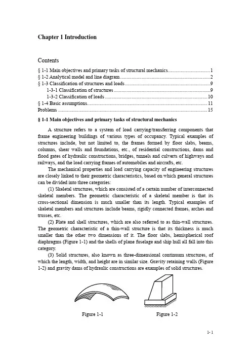
Chapter 1 IntroductionContents§ 1-1 Main objectives and primary tasks of structural mechanics (1)§ 1-2 Analytical model and line diagram (2)§ 1-3 Classification of structures and loads (9)1-3-1 Classification of structures (9)1-3-2 Classification of loads (10)§ 1-4 Basic assumptions (11)Problems (15)§ 1-1 Main objectives and primary tasks of structural mechanicsA structure refers to a system of load carrying/transferring components that frame engineering buildings of various types of occupancy. Typical examples of structures include, but not limited to, the frames formed by floor slabs, beams, columns, shear walls and foundations, etc., of residential constructions, dams and flood gates of hydraulic constructions, bridges, tunnels and culverts of highways and railways, and the load carrying frames of automobiles and aircrafts, etc.The mechanical properties and load carrying capacity of engineering structures are closely linked to their geometric characteristics, based on which general structures can be divided into three categories:(1) Skeletal structures, which are consisted of a certain number of interconnected skeletal members. The geometric characteristic of a skeletal member is that its cross-sectional dimension is much smaller than its length. Typical examples of skeletal members and structures include beams, rigidly connected frames, arches and trusses, etc.(2) Plate and shell structures, which are also referred to as thin-wall structures. The geometric characteristic of a thin-wall structure is that its thickness is much smaller than the other two dimensions of it. The floor slabs, hemispherical roof diaphragms (Figure 1-1) and the shells of plane fuselage and ship hull all fall into this category.(3) Solid structures, also known as three-dimensional continuum structures, of which the length, width, and height are in similar size. Gravity retaining walls (Figure 1-2) and gravity dams of hydraulic constructions are examples of solid structures.Figure 1-1 Figure 1-21- 1Structural mechanics is mainly focused on the study of reasonable configuration of structures and their performance in regard to the internal forces, deformation, dynamic responses and stability when under external loads and/or other external effects, such as support movements and temperature changes. The objective of the study is to make the structures to meet the requirements for safety, serviceability and economic issues. More specifically, the primary tasks of structural mechanics include the following aspects:(1) Establish a rational form for a structure considering the functional requirements and occupancy of the structure.(2) Investigate the theories and methods of calculation of the internal forces, deformation, dynamic responses and stability of the structures.(3) Investigate the theories and methods of determination of the external actions based on the structural responses, and vice versa, and those of control of structural responses.Structural mechanics is an important professional basic course of the discipline of civil engineering. It is closely linked with several prerequisite courses, including theoretical mechanics and mechanics of materials, and the subsequent elastic and plastic mechanics. The theoretical mechanics and mechanics of materials are considered as fundamental mechanics while structural mechanics is mostly focused on skeletal structures and therefore is sometimes referred to as special structural mechanics; while the elastic and plastic mechanics mostly deals with continuum structures and plate and shell structures.Advances in modern engineering technologies and rapid development of computer technologies have had a profound impact on the discipline of structural mechanics. On one hand, analysis of massive engineering structures under actions of complex external factors requires emphasizing the integrated application of basic concepts of structural mechanics and theories of conceptual engineering design. On the other hand, the rapid increase in computing capacity requires the development of compatible theories and methods of structural mechanics. As a result, the traditional structural mechanics has been boosted towards directions, including the conceptual structural mechanics and computational structural mechanics.Many fundamental changes have taken place in the roles and functions of scientific and technical personnel in the field of civil engineering due to the fast development of science and technologies. The teaching of structural mechanics should therefore focus on the basic concepts of mechanics and their rational applications, in conjunction with the cognitive rules of the objective world and context of engineering practice, and eventually aims at improving the qualities and abilities of the students as an essential goal.§ 1-2 Analytical model and line diagramIn the real sense, the load state of a structure is often very complex. It will be difficult while unnecessary in many cases to analyze the structures in full accordance with the actual states of them, and thus certain simplifications and assumptions need to be made before analyzing the structural responses. Often, during the analysis some 1- 2secondary factors of actual structures are ignored under the premise that the structural responses can still be reflected correctly. Such a simplified representation of an actual structure for structural analysis purposes is called an analytical model. In analysis of mechanics, an analytical model is representative of the actual structure. Therefore, it is a key issue and should be solved first to choose and establish a rational analytical model.The principles of selection of an analytical model include as following:(1) Retain the main factors and omit the secondary factors so that the analytical model can reflect the essential features of the structural responses, such as internal forces.(2) To simplify the analytical model as much as possible without affecting its feasibility for structural analysis.In addition, different analytical models can be used for the same structure based on the requirements and specific circumstances. For example, in the preliminary design of a structure, a relatively coarse analytical model can be used; while in the construction design, a more precise analytical model should be used. Simplified analytical models can be used for hand computation while more precise analytical models can be constructed for computerized calculation. For dynamic analyses, the analytical models can be more simplified since the analysis is often complicated and time-consuming, while for static analysis, more precise analytical models can be used as the calculation is simple and fast.An analytical model comprises simplification of actual structures in many aspects and will be introduced separately as following.1. Structural configurationsSkeletal structures can be further divided into plane and spatial skeletal structures. Generally, all actual structures are spatial structures since they need to resist loads from all directions. However, in most cases, spatial constraints that are secondary to the structural performance can often be ignored or converted into one plane, by which an actual structure can then be broken down into several plane structures. In such way, the structural analysis can be greatly simplified.2. Structural members: line diagramsMembers of a skeletal structure can normally be represented by lines coinciding with their centroidal axes. The lengths of the members are expressed as the distances between the intersection points of them and adjacent members.3. ConnectionsA connection refers to the intersection amongst the members. Although the detailed configurations of the connections of timber, steel and concrete structures are quite different, their analytical models can normally be classified into two types:(1) Pin (hinge) connectionsThe characteristic of a pin connection is that all connected members can rotate freely around the connection, and therefore it is normally represented by an idealized smooth hinge. This idealized connection, however, is very difficult to achieve in practical engineering. For example, speaking of the intermediate connection of the bottom chord of a timber roof truss, as shown in Figure 1-3a, it is apparent that the1- 3Figure 1-4a shows the details of a connection between a side column and a beam of a reinforced concrete multistory frame structure. Since the concrete of the side column and beam are cast monolithically and the reinforcing bars extend into the column no less than the required anchorage length, it is ensured that the beam and the column are firmly linked together. In this case, the connection is considered as a rigid connection and its analytical model is shown in Figure 1-4b.4. SupportsA support refers to the connection between a structure and the foundation. The loads applied onto a structural are eventually passed via supports to the foundation and soil underneath. The counterforces passed from the supports to the structure are referred to as reaction forces. For plane structures, there are mainly five types of supports:(1) Roller supportExamples of roller supports include roller bearing (Figure 1-5a) and roll shaft bearing (Figure 1-5b) used in bridges.1- 4(4) Sliding supportFigure 1-8a shows schematically a sliding support (also known as a directional pin support). This type of support limits the rotation and movement along one direction while allows sliding in the other direction of the support. For example, the structure shown in Figure 1-8a cannot rotate or move vertically at the support while it can have a small amount of sliding along the horizontal direction. This type of support1- 5(5) Elastic supportAn elastic support is used when the deformation of the support cannot be ignored for structural analysis purposes. Shown in Figure 1-9a is a bridge deck structure, for which the deck loads are passed through the longitudinal beams to the horizontal beams and girders, and eventually to the piers of the bridge. In the load transfer path, the horizontal beams support the longitudinal beams and the resulting deformation of the horizontal beams may lead to vertical displacements of the longitudinal beams. In this case, each of the horizontal beams is equivalent to a spring support to the longitudinal beams. Since this type of supports has certain ability to resist transverse movements, they are referred to as an anti-sliding elastic support. For example, the intermediate supports of the longitudinal beam shown in Figure 1-9b all fall into this category. Another type of elastic supports has certain ability to resist torsional movements, known as anti-rotation elastic support.1- 65. LoadsThe floor loads of engineering buildings can generally be simplified as uniformly distributed vertical load; the lateral wind load can be simplified along the height of the buildings as uniformly distributed (in several segments), and so on.To illustrate the process of simplification of structural loads, a single story reinforced concrete industrial workshop, as shown in Figure 1-10, is used as an example. Normally, a reinforced concrete industrial workshop is spatial and consists of roof trusses, roof sheathing panels, columns, crane beams and bracing system, etc. Vertical roof loads are passed first from the sheathing panels to the roof trusses, and then to the columns at both ends of the trusses, and eventually to the foundation. When the workshop is subjected to lateral wind loads, the loads on the roof sheathing panels will be transferred to the upper ends of the columns via roof trusses; while the wind loads on the sidewalls are generally simplified as uniform distributed loads and are transferred to the columns via the walls and eventually to the foundation. When these two types of loads act separately, all plane frames (comprising trusses and columns) except those at the sides of the workshop will generate almost the same internal forces and deformation; therefore, the structural analysis of the building can be based on the analysis of one of these plane frames. Thus, a spatial problem can be simplified to a plane problem. It is well known that the longitudinal connections (mostly achieved by bracings) of the workshop is relatively weak and cannot provide sufficient integrity. Therefore, when the workshop is subjected to vertical or horizontal crane loads, it is conservative to assume that all or a certain percentage of the crane loads are resisted by the frame right underneath the crane(s). Thus, the workshop can still be analyzed as a plane system.1- 71- 8 Figure 1-10 1Fixed steel skylightRibbed sideboard Sheathing panel ColumnWindowBeamDitch Exterior wall LintelSteel bracketCullis board CranebeamGround Concrete padCup-shaped foundation Crane ladderWind column§ 1-3 Classification of structures and loads1-3-1 Classification of structures2. ArchesNormally the centroidal axis of an arch is curved. Arches will have horizontal reaction force under vertical loads, which helps to reduce the bending moments on the cross-sections (Figure 1-13).1- 93. Rigid framesA rigid frame usually consists of straight members. Its configuration is characterized by rigid connections at intersections of members (Figure 1-14). Sometimes a rigid frame is also called a frame.Figure 1-13 Figure 1-144. TrussesTrusses consist of straight members, which are all pin-connected. When a truss is subjected to nodal forces only, there will be only axial forces in truss members (Figure 1-15).5. Composite structuresA composite structure comprises truss members and beams (Figure 1-16a), or truss members and rigid frame members (Figure 1-16b). The feature of its load state is that its truss members only take axial force and all the other flexural members can resist axial force, shear force and bending moments simultaneously.In addition to the five types of skeletal structures mentioned above, which are the most basic, there are more complex ones, such as suspension cable structures.Figure 1-16Skeletal structures can be plane or spatial. When the centroidal axes of the members and the applied loads are in the same plane, it is known as a plane skeletal structure, or simply a plane structure. Those do not meet these conditions are known as spatial skeletal structures, or simply spatial structures (see § 3-6).1-3-2 Classification of loadsLoads refer to the external forces acting on a structure. For example, the 1- 10self-weight of a structure, crane loads of industrial workshops, loads from cars driving on a bridge, soil or water pressure acting on hydraulic structures, and so on.The various types of loads can be briefly classified as follows based on their duration and nature:1. Classified based on duration of load(1) Dead loadsLoads that act permanently on a structure of constant magnitudes and fixed positions are known as dead loads. For example, the self-weight of a structure and the weight of the devices that are permanently attached to the structure. A dead load does not change in terms of its magnitude, position and direction during the service life of a structure.(2) Live loadsA load of a variant magnitude and only temporarily acts on a structure is known as a live load. Examples include loads caused by train and cranes, people, wind, snow and so on. In structural analysis, usually dead loads and some live loads (such as people, wind and snow loads) are considered as fixed in terms of their position, and are therefore called as fixed loads. Some live loads, such as loads brought by cranes, cars and trains, are referred to as moving loads since their positions on a structure are variable.2. Classified based on the nature of loads(1) Static loadsStatic loads have constant magnitudes, positions and orientations over time, and are normally assumed to be increased gradually from zero to a sustained value. Consequently, the mass of a structure under static loading will not produce apparent acceleration and inertia forces, and thus will not cause vibration of the structure. Self-weight of structures and other dead loads all belong to static loads.(2) Dynamic loadsDynamic loads change rapidly over time. The structures under dynamic loads will generate apparent acceleration and corresponding inertia forces, which will subsequently cause structural motion or vibration. For example, loads caused by eccentric masses of a running machine, dynamic actions on structures caused by ground motion during an earthquake, impact actions from waves on hydraulic structures, blast waves from an explosion, fluctuating loads caused by wind, and so on, all belong to dynamic loads.§ 1-4 Basic assumptionsIn addition to various simplifications made in construction of analytical models of structures, structural analysis can also be simplified by taking assumptions of the structural behavior based on the actual situations.Structural mechanics usually considers the following three basic assumptions:(1) Structures are continuous and remain so when subjected to external loading.(2) Hooke’s Law applies, which states that, for a structure in static equilibrium, the displacement u at any point (Figure 1-17) can be expressed asn n F a F a F a u P P P +++=L 2211 (1-1)where a1, a2… and a n are constants and independent of the loads F P1, F P2... and F Pn; however, the constants are normally different for displacements of different points on the structure and different positions and orientations of the external loadings.(3) A structure recovers its original unstressed state if all external loads are withdrawn.The structures that are analyzed based on these three assumptions are known as linear elastic structures. At year 1859 Kirchhoff proposed the uniqueness theorem of solution of elastic systems, according to which the elastic deformation of a linear elastic system has unique relationship with the external loads, i.e., the internal force and deformation of a linear elastic system are uniquely determined given the external loading actions. The theorem of uniqueness of solution of linear elastic system plays an important role in structural analysis. A structural analysis based on this theorem is known as a linear analysis.Figure 1-18The principle of superposition of linear elastic structures can be proved based on the assumptions (2) and (3), i.e., Equation (1-1) applies to a series of load vectors F P1, F P2... F Pn not only when they are at a constant ratio but also when they are in arbitrary ratios to each other. In other words, the applicability of Equation (1-1) is independent of the loading sequence, so are the constants a1, a2…and a n. The principle of superposition plays an important role in structural analysis of linear elastic structures.Besides, some other important theorems, such as the reciprocal theorem (see §5-7), can also be derived from the three basic assumptions.In real engineering practice, some structures do not meet the basic assumptions. Such structures are known as nonlinear structures. The analysis of such structures is called a non-linear structural analysis. The nonlinearity in structural behavior mainly comes from the nonlinearity in material behavior and geometric characteristics of the structures.The so-called material nonlinearity refers to the physical properties of structural materials in case they are nonlinear, including nonlinear elastic and plastic. For example, as shown in Figure 1-18, the material near the midspan (with the shadowed area) of a simply supported steel beam can exhibit nonlinearity when the loadbecomes large. In this case, the relationship between the internal forces, deformation and the external loading becomes nonlinear.The so-called geometric nonlinearity refers to the phenomenon that the deformation or displacement of a structure gets so large that the equilibrium conditions can only be applied based on the deformed configuration of the structure. Figure 1-19a shows an eccentrically compressed column. When the translational displacement, Δ, of the upper end of the column is small compared to the loadeccentricity e, the equilibrium conditions can be applied to the original configuration of the column without causing too big errors. Consequently, the bending moment at the bottom end of the column, M A, is considered to be equal to F P e. Otherwise, if Δ is large compared to the load eccentricity e and cannot be ignored, the equilibrium conditions must be established based on the deformed column configuration, i.e., M A=F P(e+Δ). Since the translational displacement Δ is a function of F P, both thedeformation and internal forces of the column will be nonlinear.Another example is shown in Figure 1-19b, where the structure reaches equilibrium under an external load applied at point A. The deformed configuration is represented by dashed lines. Since the displacement is quite large compared to the dimension of the structure, the equilibrium equations for the calculation of the internal forces of the two tension rods must be constructed based on the deformed configuration. Since the deformed configuration of the structure is dependent on the external loading, the deformation and internal forces are also nonlinear with the external loading.Figure 1-19c shows a curved bar subjected to a vertical load. The support conditions of the curved bar are dependent on its deformation. This nonlinearity in boundary conditions can also be regarded as geometric nonlinearity. In fact, the force equilibrium is always reached on the deformed configuration of a structure no matter how big the structural deformation or displacement is. It is only that ignoring the difference between the deformed and original configurations of a structure will not cause significant errors when the structural deformation or displacement is small enough.Figure 1-19For nonlinear structures the theorem of unique solution and the principle ofFor most actual structures, the stress-strain relationship of the materials will be close to (for example steel structures) or can be approximately considered (frame example reinforced concrete structures) as linear. Meanwhile, the structural deformation and displacement will be quite small compared to the dimension of the structure. In this case, the three basic assumptions hold and the theorem of unique solution and the principle of superposition apply. Chapters 1 to 10 of this book will mainly discuss the linear elastic structural analysis.Problems[1-1]What are the major differences in the geometric configurations of skeletal structures, plate and shell structures and continuum structures?[1-2]What are the basic tasks of structural analysis and the major problems that should be paid attention to during the study of structural mechanics?[1-3]What is the analytical model of a structure? How to choose an analytical model?[1-4]What is the major difference and possible relationship between moving loads and dynamic loads?[1-5]What is a linear elastic structure and what are the basic characteristics of the structural behavior of linear elastic structures? What is the basic meaning ofHooke's law?[1-6]What are the basic characteristics of structures with material nonlinearity and geometric nonlinearity?。

第1章1-1分析图示体系的几何组成。
解 原体系依次去掉二元体后,得到一个两铰拱(图(a-1))。
因此,原体系为几何不变体系,且有一个多余约束。
1-1 (b)解 原体系依次去掉二元体后,得到一个三角形。
因此,原体系为几何不变体系,且无多余约束。
(a )(a-1)(b )(b-1)(b-2)1-1 (c)(c-2) (c-3)解 原体系依次去掉二元体后,得到一个三角形。
因此,原体系为几何不变体系,且无多余约束。
1-1 (d)(d-1) (d-2) (d-3)解 原体系依次去掉二元体后,得到一个悬臂杆,如图(d-1)-(d-3)所示。
因此,原体系为几何不变体系,且无多余约束。
注意:这个题的二元体中有的是变了形的,分析要注意确认。
(d )(c-1)1-1 (e)解 原体系去掉最右边一个二元体后,得到(e-1)所示体系。
在该体系中,阴影所示的刚片与支链杆C 组成了一个以C 为顶点的二元体,也可以去掉,得到(e-2)所示体系。
在图(e-2)中阴影所示的刚片与地基只用两个链杆连接,很明显,这是一个几何可变体系,缺少一个必要约束。
因此,原体系为几何可变体系,缺少一个必要约束。
1-1 (f)解 原体系中阴影所示的刚片与体系的其它部分用一个链杆和一个定向支座相连,符合几何不变体系的组成规律。
因此,可以将该刚片和相应的约束去掉只分析其余部分。
很明显,余下的部分(图(f-1))是一个几何不变体系,且无多余约束。
因此,原体系为几何不变体系,且无多余约束。
1-1 (g)解 原体系中阴影所示的刚片与体系的其它部分用三个链杆相连,符合几何不变体系的组成规律。
因此,可以将该刚片和相应的约束去掉,只分析其余部分。
余下的部分(图(g-1))在去掉一个二元体后,只剩下一个悬臂杆(图(g-2))。
因此,原体系为几何不变体系,且无多余约束。
(e )(e-1)ABCAB (e-2)(f )(f-1) (g ) (g-1) (g-2)1-1 (h)解 原体系与基础用一个铰和一个支链杆相连,符合几何不变体系的组成规律。
第1章1-1剖析图示系统的几何构成。
1-1(a)a〕原系统挨次去掉二元体后,获得一个两铰拱〔图〔原系统为几何不变系统,且有一个剩余拘束。
1-1(b)b〕〔b-1〕a-1〕(a-1〕〕。
所以,b-2〕解原系统挨次去掉二元体后,获得一个三角形。
所以,原系统为几何不变系统,且无剩余拘束。
1-1(c)〔c〕〔c-1 〕〔c-2〕〔c-3〕解原系统挨次去掉二元体后,获得一个三角形。
所以,原系统为几何不变系统,且无剩余拘束。
1-1(d)〔d〕〔d-1〕〔d-2〕〔d-3〕解原系统挨次去掉二元体后,获得一个悬臂杆,如图〔d-1〕-〔d-3〕所示。
所以,原系统为几何不变系统,且无剩余拘束。
注意:这个题的二元体中有的是变了形的,剖析要注意确认。
1-1(e)AAB C B〔e〕〔e-1〕〔e-2〕解原系统去掉最右侧一个二元体后,获得〔e-1〕所示系统。
在该体系中,暗影所示的刚片与支链杆C构成了一个以C为极点的二元体,也能够去掉,获得〔e-2〕所示系统。
在图〔e-2〕中暗影所示的刚片与地基只用两个链杆连结,很显然,这是一个几何可变系统,缺乏一个必需拘束。
所以,原系统为几何可变系统,缺乏一个必需拘束。
1-1(f)〔f-1〕f〕原系统中暗影所示的刚片与系统的其他局部用一个链杆和一个定向支座相连,切合几何不变系统的构成规律。
所以,能够将该刚片和相应的拘束去掉只剖析其他局部。
很显然,余下的局部〔图〔f-1〕〕是一个几何不变系统,且无剩余拘束。
所以,原系统为几何不变系统,且无剩余拘束。
1-1(g)〔g〕〔g-1〕〔g-2〕解原系统中暗影所示的刚片与系统的其他局部用三个链杆相连,切合几何不变系统的构成规律。
所以,能够将该刚片和相应的拘束去掉,只剖析其他局部。
余下的局部〔图〔g-1〕〕在去掉一个二元体后,只剩下一个悬臂杆〔图〔g-2〕〕。
所以,原系统为几何不变系统,且无剩余拘束。
1-1(h)〔h〕〔h-1〕解原系统与根基用一个铰和一个支链杆相连,切合几何不变系统的构成规律。