fm350高速计数器模块速成使用手册
- 格式:pdf
- 大小:485.30 KB
- 文档页数:4

计数模板FM350-2 快速使用入门 FM350-2 Getting started该文档主要面对初次使用FM350-2模板的用户。
内容包括一些调试的步骤,使用经验,等等。
但是,该文档无法取代FM350-2的手册。
建议:用户通过此文档掌握了初步调试和使用模板的方法以后,还是要认真、仔细阅读FM350-2的手册,进一步加深对FM350-2功能模板的理解。
FM350-2模板的使用者,应该具有STEP 7操作的基础知识。
关键词FM350-2 高速计数Key WordsCounterspeedFM350-2 High目录1.FM350-2 快速入门 (4)1.1 模块概述 (4)1.2 准备工作 (4)1.3 FM350-2的安装和接线 (5)1.4 测试模块 (8)1.5 产生一个高速计数模块FM350-2的数据块 (8)1.6 分配参数给高速计数模块FM350-2 (8)1.7 没有用户程序的情况下,调试高速计数模块FM350-2 (11)1.8 程序编制 (15)1.8.1. 基本介绍 (15)1.8.1.1. 简介 (15)1.8.1.2. 硬件组态 (16)1.8.1.3. 编程基本规则 (16)1.8.1.4. 通过访问I/O直接读取计数值和测量值 (16)1.8.2. 操作模式介绍 (18)1.8.3. 数据块介绍(Data Block) (19)1.8.4. 中断程序 (24)1.8.5. 例子程序fm_cntex(Zxx34_01_fm350-2)说明 (26)1.8.5.1. 硬件组态介绍 (26)1.8.5.2. 程序结构的说明 (27)1.8.5.3. OB1程序简介 (28)1.8.5.4. FC100程序简介 (30)1.8.5.5. OB82程序简介 (33)1.9 编码器的选择 (33)1.10 错误诊断 (33)2.FM350-2 常见问题分析(FAQ) (34)2.1 西门子自动化与驱动产品的在线技术支持...........................E RROR!B OOKMARK NOT DEFINED.2.2 如何获得西门子自动化与驱动产品的资料...........................E RROR!B OOKMARK NOT DEFINED.2.3 需设备选型及订货...............................................................E RROR!B OOKMARK NOT DEFINED.2.4 西门子技术支持热线............................................................E RROR!B OOKMARK NOT DEFINED.2.5 西门子自动化产品的其它网站.............................................E RROR!B OOKMARK NOT DEFINED.2.6 标准及认证 (34)2.7 FM350-2搬运、存储、运行的环境要求 (34)2.8 FM350-2配置软件包V4.0+SP3 (35)2.9 FM350-2入门文档 (35)2.10 FM350-2的产品手册 (35)2.11 FM350-2的产品手册...........................................................E RROR!B OOKMARK NOT DEFINED.2.12 怎样直接通过模板的I/O逻辑地址访问FM350-2计数值 (35)2.13 FM350-2可以通过IM365接口模板,放置在扩展机架吗.....E RROR!B OOKMARK NOT DEFINED.2.14 为什么FM350-2库文件的帮助文件中,出现错误文字显示 (35)1. FM350-2 快速入门1.1 模块概述通道智能型计数器模块,用于通用计数和测量任务;• 8•直接连接 24 伏增量编码器和8.2伏NAMUR 编码器;•与可编程参考值的比较功能(工作方式决定比较值数量);•当达到比较值时,内置数字输出端输出响应;•多种工作模式¾连续/ 单次/ 周期计数¾频率/ 速度的测量¾周期测量¾比例器1.2 准备工作•有一个S7-300 PLC站,由电源模块,工作存储器大于等于12KB的CPU和FM 350-2 摸板组成。

First Steps in CommissioningThis guide uses a specific example to introduce you to starting up your FM 350-1 module. It uses four steps to lead to a functioning application in which you count the switching operations of a contact and become familiar with and test the basic functions of the hardware and software of your FM 350-1. The references to the manual are intended to give you an initial overview of the information in the manual. The references refer to the “FM 350-1 Function Module” manual wi th the number A5E00073040-01. The timerequired to work through the example will be approximately 1 to 2 hours, depending on how experienced you are.RequirementsThe following requirements must be fulfilled:•You must have an S7-300 station comprising a power supply module and a CPU.•STEP 7 (≥V4.02 is correctly installed on your programming device (the example given in this Getting Started was carried out with STEP 7 V5.0.•You have set up a project for the S7-300 station.•The programming device must be connected to the CPU.•You must have an FM 350-1 module, the configuration package for the FM 350-1, and the necessary accessories such as a bus connector, front connector, sensors or switches, and wiring material.Installing the Configuration Package on the Programming Device(Manual Chapter 5The configuration package contains a configuration tool for the FM 350-1, the functions (FC and the data structure (UDT required, and a sample program.Insert the CD in the CD drive.Under Windows start the dialog for installing software by double-clicking the “Add/Remove Programs”symbol in “Control Panel”.Click Install... , start the Setup.exe file on the CD in the FMx50-1\Disk1 folder and follow the instructions of the installation program.Installing and Wiring the FM 350-1 (Manual Chapter 3 and 4To connect the 24-V sensor used in the example you must insert the coding key on the module in position D before you insert the FM 350-1. This sets the adjustment to the sensor level (you will find more information on the coding key in Sections 1.3 and 3.2 of the manual.Plug the bus connector supplied with the FM 350-1 into the bus connector on the CPU. Hang theFM 350-1 into the rail, swing it downwards, and screw it in place (you will find more detailed instructions in Section 3.2 of the manual.Wire up the front connector as follows (you will find the full pin assignment of the front connector in Chapter 4 of the manual:Insert the front connector in the FM 350-1 and snap it into place.Test:Switch on the voltage on the power supply module. The red LED SF lights up. After you have switched on the power supply module for the first time, the FM 350-1 is in the preset default state (refer to Section 4.3 of the manual for default settings.Assigning Parameters to the FM 350-1Open your project in the SIMATIC Manager.Open the configuration table (HW Config in your project.From the hardware catalog select the FM 350-1 with the correct order number and drag it to the required slot (in the example: slot 4.Call the parameter assignment screen forms by double-clicking on this FM 350-1. To do this, you may have to close the dialog asking you to save the configuration with OK.Select the following settings by clicking on the buttons in the parameter assignment screen forms (please leave all other settings unchanged, as they are not yet required for commissioning:•Operating Modes:0 to +32 Bit, Continuous Counting, Hardware Gate•Encoders:24V Initiator, P Switch•Inputs:Level-Controlled Hardware Gate•Process interrupt enable:not p ossible as deselected in basic parameters•Outputs:DQ0 Inactive, DQ1 Inactive•Reaction to CPU stop:STOPEnter the FM 350-1 parameter assignments in your configuration using the menu command File →Save and close the parameter assignment window.Save the configuration created by you in your project using Station>Save and Compile.Download the configuration with the CPU in STOP mode using the menu command PLC →Download T o Module.The data are now downloaded directly to the CPU and into the FM 350-1. The red LED SF extinguishes. From now on, as long as the configuration remains buffered in theCPU, the data will be transferred from the CPU to the FM 350-1 every time the CPU switches from STOP to RUN.Test:You can now run simple tests without a program:Close the gate contact: the green LED I0 lights up.Close and open the count contact several times: you can monitor the state of the leastsignificant bit of the FM 350-1 counter via the green LED CR.Note that a mechanical count contact can bounce.When you open the gate contact, the gate LED I0 extinguishes and no more switchingoperations are counted (the timing diagram for this function can be found in Section 2.2 of the manual.Integrating into the User ProgramOpen the library FMx50LIB in the SIMATIC Manager using the menu command File →Open...Libraries.Copy the functions FC0 and FC1 and the user-defined data type UDT1 from the “Blocks” container of the FMx50LIB library to the “Blocks” container of your project.Insert DB1 in the “Blocks” container using the menu command Insert → S7 Block → Data Block. Open DB1 and create the DB1 as a data block referencing the user-defined data type UDT1.Save the DB 1 with File>Save and then close with File>Close.Open the popup menu in HW Config by clicking with the right mouse button on the FM350-1 entry. Using the Object Properties menu command start the Properties –FM350-1 COUNTER screen form. Using the Mod Addr... button you can now automatically enter the module address (MOD_ADR (in the example: 256 corresponds to 100 Hex, the channel address (CH-ADR and the channel length set under Addresses in the channel data block.You can achieve this by clicking the Select DB button in the Module Address for DB screen form. Click and select the DB 1 in the Open dialog which was started . By clicking OK the values are stored inDB 1 and the Open and Module address for DB screen forms are automatically closed. Exit the Properties – FM350-1 COUNTER screen form with OK.Alternatively you can also supply these parameters to DB1 in OB100 (see manual, Section 6.1. Open OB 1 in your project.Call FC0 in OB1 and supply parameters to FC0 (see manual, Section 6.1:CALL FC 0DB_NO := 1::Assign all remaining parameters of FC0 with free memory bits.Save OB1 using the menu command File → Sav e.Select all the blocks in your project (apart from VAT and UDT.Download your program to the CPU using the menu command PLC → Download.Test:Using the “Monitoring and Modifying Variables” application you can now monitor the count value and the gate, for example:In your project select the “Blocks” container. Insert the variable table VAT1 using the menucommand Insert → S7 Block → Variable T able and confirm with OK.Open the variable table VAT1 and enter the following variables in the “Address” column:db1.dbd34(actual count valuedb1.dbx43.6(status of internal gateSave the variable table VAT1 using the menu command Table → Sav e.Switch online using the menu command PLC → Connect To →Configured CPU.Switch to monitoring using the menu command Variable → Monitor.Switch the CPU to RUN-P.Generate pulses with the count contact and monitor the count value with relation to the state of your gate contact.DiagnosticsErrors can occur as a result of incorrect operation, incorrect wiring, or contradictory parameter assignments which the FM 350-1 displays with the group error LED SF.Refer to Section 6.2 and Chapter 13 of the manual for information on how you can diagnose errors and messages.ExampleIn the zEn23-1 project you will find another example which you can use to guide you and which you can adapt to your application.。

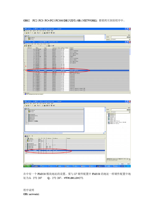
OB82 FC2/ FC3/ FC4/FC5/FC300/DB2/UDT1/0B1 NETWORK1 都要拷贝到原程序中。
在中有一个FM350模块地址的设置。
要与S7硬件配置中FM350的地址一样硬件配置中地址为I:272-287 Q:272-287。
=W#16#110=272.程序说明OB1 network1CALL "CiShan" //调用FC300程序块cnt2_app :=W#16#2 //背景数据块号DB2quantity :=MW4 //预装载值,为MW4赋值,当前为零,也可以用W#16#0 load := //装载计数器值,计数器应用时此点为1Gate0_3 := //打开计数器0-3通道的软件门Gate4_5 := //打开计数器4-5通道的软件门act_val := //开始读当前计数值的触发位channel := //0为计数器通道0-3计数1为为计数器通道4-7计数,应置1rd_err := //读操作的出错提示wr_err := //写操作的出错提示load_done := //装载计数器操作的状态指示state_oflw:= //通道4测量值上限溢出状态指示state_uflw:= //通道4测量值下限溢出状态指示FC300 程序说明network1L #cnt2_app //Application fill unitT #cnt2_db //Open counter data blockOPN DB [#cnt2_db]CALL "CNT2_CTR" //Control the FM 350-2 调用FC2DB_NO:=#cnt2_dbA DBX //FM 350-2 parameters assigned?JCN END //No, process no applicationA DBX //Lower limit exceeded?= #state_uflwA DBX //Upper limit exceeded?= #state_oflwA #Gate0_3 //Start the fill unit?= DBX //Yes, SW_GATE0 open= DBX //Yes, SW_GATE1 open= DBX //Yes, SW_GATE2 open= DBX //Yes, SW_GATE3 openA #Gate0_3 //Start the fill unit?A DBX //Yes, CTRL_DQ0 = STAT_GATE0= DBX //and trigger fill valveA #Gate0_3 //Start the fill unit?AN DBX //Yes, invert STA T_DQ0= DBX //and trigger motor for transport= DBX //with CTRL_DQ1 and SET_DQ1A #Gate4_5 //Start the frequency measurement?= DBX //Yes, SW_GATE4 open= DBX //Yes, SW_GATE5 open// = DBX //Yes, SW_GA TE6 open 想要使用通道6将前面注释符去掉// = DBX //Yes, SW_GA TE7 open 想要使用通道7将前面注释符去掉network2SET //Set BR for error evaluationSA VEOPN DB [#cnt2_db] //Open counter data blockA DBX //Load comparator in progress?JC WRDO //YesA DBX //New loading only during transportJCN WRENA #load //Load new quantity?FP M //Positive edge to #load 注意不能和程序其它地方应用冲突JCN WREN //NoL #quantity //Quantity in counter data blockT DBD 116L 42 //job_no 30 forT DBB 0 //Load comparator count channel 0 WRDO: CALL "CNT2_WR" //Load counter and comparator for FM 350-2DB_NO :=#cnt2_dbRET_V AL:=MW6 //注意不能和程序其它地方应用冲突WREN: AN BR //Error: job_no unknown, retval_wr with error or dataerror= #wr_errAN #load //Create write job endedR DBX //Deleted when loading triggeredA DBX= #load_donenetwork 3SET //Set BR for error evaluationSA VEOPN DB [#cnt2_db] //Open counter data blockA DBX //Read actual values in progress?JC RDDO //YesAN #act_val //Reading actual values?JC RDEN //NoL 100 //job_no 100 for count channel 0 to 3AN #channel //for count channel 4 to 7?JC JOBL 101 //job_no 101 for count channel 4 to 7JOB: T DBB 2 //Load comparator count channel 0RDDO: CALL "CNT2_RD" //Load counter and comparator for FM 350-2DB_NO :=#cnt2_dbRET_V AL:=MW8 //注意不能和程序其它地方应用冲突RDEN: AN BR //Error: job_no unknown or retval_rd with error= #rd_errEND: BE。

Simotion连接FM350模块Simotion Connect with FM350摘要 本使用入门做为 SIMOTION 附加编程参考文档的一部分,为SIMATIC FM 350-1 高速计数功能模块手册提供了如何通过Simotion来控制它的补充说明,为正确将FM350-1模块集成到Simotion控制系统中并完成调试提供帮助。
关键词Simotion,FM350-1Key Words Simotion,FM350-1IA&DT Service & Support Page 2-21目录一、概述 (4)二、产品描述 (4)三、安装及连接 (5)四、在SIMOTION项目中插入功能模块 (6)1.硬件组态 FM 350-1(分布式应用) (6)2.在用户项目中集成FM 350-1控制功能块 (6)五、FM350-1功能块 (9)1.概述 (9)2.功能块“_FM3501_control” (9)3.功能块“_FM3501_diagnostic” (12)4.FM350-1的数据结构 (14)5.功能块调用 (16)五、FM350-1应用程序示例 (19)1.使用的输入符号 (19)2.使用的输出符号 (19)3.示例内容 (19)IA&DT Service & Support Page 3-21一、概述本章描述了FM350模块在 SIMOTION 系统及 SIMATIC 系统中运行的相同及不同之处,它做为SIMATIC 手册“FM 350–1 Function Module Installation and Parameter Assignment”的补充部分。
对于Simotion系统,需要下述软件版本:• SIMOTION SCOUT V4.0 或更高• SIMOTION Kernel V4.0或更高• SIMOTION technology packages V4.0或更高Simotion 功能块不支持FM 350-1 模块(订货号:6ES7 350-1AH03-0AE0)的下述新功能: • 同步模式• 测量模式 (频率测量,速度测量,周期测量)二、产品描述FM 350-1FM 350-1 计数模块是一个单通道的高速计数模块,计数范围为:• 0 to 232 - 1• -231 to 231 - 1计数信号的最大输入频率为 500 kHz。

FM350 高速计数器模块怎么用
如题,请教高速计数器模块如何使用?
看程序是调用标准功能FC0,这个功能的各个形参代表什么呢?
为什么我两个编码器,都是用的FM350计数器模块,转动时间大致差不多,但是一个输入值9000多,另外一个输入值20000多,哪里可以设置吗?
最佳答案
FM350高速计数器模块怎么用,你可以下载入门手册进行学习——
《FM350-1/FM350-2常问问题集》下载:
/download/Upload/AS/faq/F050 9.pdf
《FM350-1工作原理及使用入门》下载:
/download/Upload/AS/applicati on/A0479.pdf
《FM350-1使用入门文档》下载:
/download/Upload/AS/applicati on/A0370.pdf
《FM350-2快速入门》下载:
/Download/Upload/AS/applicati on/A0025.pdf
《FM350-2计数模块的安装和参数配置》下载:
/download/Upload/AS/manual/1 105178.pdf
《SIMATICFM350-1功能模块》下载:
/download/Upload/AS/manual/1 086726.pdf。
FM 350-1常见问题分析目录1高速计数器FM350-1是连结增量型编码器的功能模板。
如何做到断电保持上次的计数值 (2)2升级FM350-1(6ES7 350-1AH03-0AE0)的固件版本,从V1.0.0 到 V1.0.2 (3)3已经通过CD正确安装配置FM350-1模板的软件,但是在“STEP 7 V5.1 +SP6”的硬件组态中,无法发现硬件FM350-1 (6ES7 350-1AH03-0AE0) (3)4FM350-1 (6ES7 350-1AH03-0AE0)电子手册 (3)5FM350-1 (6ES7 350-1AH03-0AE0)的产品信息 (3)6下载配置FM350-1,FM450-1的软件包V5.1(03.2003) (3)7当使用IM365扩展接口模板做系统配置时,是否可以使用FM350-1模板 (3)8数据块部分信息介绍(DATA BLOCK) (3)9如何快速预装载计数值 (5)10是否在FM450-1组态包里,用于显示硬件门控制器的图像是颠倒的 (6)11FM450-1在仅仅使用通道0时,模板总报告通道1的信号有错误,外部错误··612FM450-1的电子手册 (6)13FM450-1的快速入门手册“GETTING STARTED MANUAL” (7)1 高速计数器FM350-1是连结增量型编码器的功能模板。
如何做到断电保持上次的计数值高速计数模板的计数当前值,都是存储在CPU的数据块DB中,不会丢失。
可以如下编程处理:i. 在每次CPU上电时候,OB100中进行初始化程序处理——传递CPU数据块DB中的当前计数值DBD34,放置到装载数值DBD14中。
调用功能块“CNT_CTL1Function”,置位操作“L_PREPAR”;ii. 在OB1中调用功能块“CNT_CTL1 Function”,使用脉冲上升沿信号触发操作“L_DIRREC”;iii. 即可以做到断电保持上次的计数值,开始正常的高速计数操作。
编者注:此文档尽对软件设置进行简单描述,目的是记录末架轧机脉冲数并带锁存功能,相关硬件知识请参照FM350-1光盘中使用手册。
建议:首先请简单阅读用户手册相关内容,再做此实验。
目录:1.1实验平台 (2)1.2准备工作 (3)1.3硬件组态 (4)1.4程序调试 (8)1.1实验平台z电源模块:307-1EA00-0AA0z CPU模块:315-2AG10-0AB0z存储卡:953-8LG10-0AA0z高速计数模块:350-1AH03-0AE0 z编码器:EB58B10-H6PR-1024z STEP7 5.4.0.0z FM350-1软件包(模块光盘中)1.2准备工作z搭建实验平台z安装软件包(先要安装STEP7)1.3硬件组态z建立一个新项目z插入一个300站z组态硬件(如图1)图1z双击FM350 COUNTER,出现COUNTER MODULE画面(图2)图2z进入Operating Modes,修改Gate的模式为Latch(图3)图3z进入Encoders,修改Signal Type为24V incremental(图4)图4z进入Input,修改Set Counter(Set DI)为Multiple,同时取消Evaluate zero mark for setting(图5)图5z进入Output,修改DO1为Active on reaching the comparison value for pulse duration(up),把Pulse duration改为500ms(图6)图6z保存设置,编译并下载1.4程序调试z打开Libraries,选择FMx50Lib(图7)图7z复制FC2和UDT1到实验工程中(图8)图8z回到实验项目,插入DB1(图9)图9z编程注意事项¾必须要赋值的三个参数DB1.DBW6(高数模块地址),DB1.DBD8(高数模块地址首址),DB1.DBB12(高数模块地址长度)(图10)图10¾必须置位的点,FC2中的SW_GATE(允许计数),DB1.DBX27.0和DB1.DBX27.1(允许硬件I2清零),DB1.DBX28.0和DB1.DBX28.1(允许硬件Q0和Q1输出)¾FC2说明(主要参数说明)(图11)DB_NO 对应DB块的DB号,本例为1SW_GATE 软件门,为“真”的时候,允许计数L_DIRECT 软件清零L_PIRPER 设置LOAD_V AULT_CMP_V1 设置比较值1(对应DO1)T_CMP_V2 设置比较值2(对应DO2)图11¾当前值为DB1.DBD30,锁存值为DB1.DBD34(硬件I0出现上升沿,当前值就被锁存到DB1.DBD34中)(图12)图12¾设置DB1.DBD14(装载值):在给DB1.DBD14赋值的同时,必须给FC2FM350-1调试说明(适用于飞剪系统) TJ-BJ自动化2室-马楠的L_PREPAR为“真”一次¾设置DB1.DBD18(比较值1)和DB1.DBD22(比较值2):在给DB1.DBD18和DB1.DBD22赋值的同时,必须给FC2的T_CMP_V1和T_CMP_V2为“真”一次\\自动化2室-1\f\自动化2室文档\调试报告\调试报告pdf文档\ 11。
FM350-2高速计数器实例A:在《FM350-2入门指南》和《FM350-2使用入门》中,就列出了西门子的样例程序和库文件的打开办法。
实际应用中,找到相应的任务号传送到DB块的寄存器中。
任务号要看《FM350-2安装和参数配置》。
Q:看了这说明书还是不太理解,硬件地址是480-495,不知如何写数,这数的意思还是不太理解。
A:如果在硬件设置里指定了该模块对应的DB块【Module adress for datablock】,那么模块的逻辑地址和通道地址无需在程序中再次编程设定。
然后调用FC2,同时指定前期生成的DB块号;然后调用FC4,并通过对DBB2设置工作号100或101来对0~3或4~7号通道进行读值;0~7通道对应的编码器值,为DBD148、DBD156……DBD204。
Q:DBB2设置工作号100或101什么意思,找不到啊,DBD148、DBD156……DBD204又不智道道在那,我选了db1数据块A:简单的编程:网络1:M100.0的常闭点一直通;网络2:必须调用FC2(CNT2_CTR),指定W#16#1即为设定FM250-2的数据块为DB1;网络3:打开其软件门DB1.DBX23.0对应第一通道,DB1.DBX23.1对应第二通道,用几个通道就依次置ON几个;网络4:将任务号100写入DB1.DBB2,工作号100的意思是读前4个通道的计数值;工作号101的意思是读后4个通道;网络5:调用FC4(CNT2_RD),执行读数,W#16#1同样是指定DB块号。
此时在程序中调用DB1.DBD148,即可获得计数器0的计数值;调用DB1.DBD156,可获得计数器1的计数值。
工作号的含义:其实对简单的使用来说用不到几个的。
就用上边提到的就可以读出计数器值了。
以下工作号参考使用【《FM350-2使用入门》例程中有提到】Q:DB1.DBB2是数据块db1内的2.0吗?DB1.DBB2的B2是字节2的意思吗,W#16#1是不是模块的地址号啊?A:DB1.DBB2是数据块db1内的2.0吗?DB1.DBB2的B2是字节2的意思吗。
FM350-1高速计数模块使用一、安装1、信号类型2、外部接线二、设置1、计数范围:2、计数方式:连续计数:当向上计数,在到达计数上限后,在下一个脉冲到来,计数值跳到下限然后再次开始加计数。
单向计数:计数器从装载值开始计数。
当向上计数,在到达计数上限后,在下一个脉冲到来,计数值跳到计数下限值,并且即使再有脉冲到来,计数值仍保持在计数下限值。
当向下计数,在到达计数下限值后,在下一个脉冲到来,计数值跳到计数上限值,并且即使再有脉冲到来,计数值仍保持在计数上限。
周期计数:计数器从装载值开始计数。
当向上计数,在到达计数上限后,在下一个脉冲到来,计数值跳到装载值然后再次开始加计数。
当向下计数,在到达计数下限值后,在下一个脉冲到来,计数值跳到装载值然后再次开始减计数。
三、编程1、“L-DIRECT”、“L-PREPAR”参数:“L-DIRECT”参数定义:将装载值传送到装载寄存器,并直接进入计数器;“L-DIRECT”参数定义:将装载值仅仅储存在装载寄存器;2、“Gate”功能3、计数器控制功能“FC0”4、对于套塑辅牵的控制:1.跟踪主牵引变频的变频输出,速度可同步,但在启动时,由于低频会有抖动2.辅牵使用跟光纤放线架一样的PID控制,速度可正反转可快速反应,但在有时突然反转,会造成机械冲击,容易磨损方销,现7#TS采用此法,215-17.5205-50227-1440-0.4441-0.773.对于原来的伺服电机控制,是因为升速不能达到要求,PLC输出控制两个牵引,速度到280时,就会有干扰,4.有的是PLC有7个模块的就是说有两路输出到牵引,分别控制主牵引和辅牵引,通过PLC内部做的PID控制,也是比较平稳的。
但就是要多增加模块。
本人反省1,8月份来又上保养班了,但现在的感觉不知道怎么回事,很累,空的时间少了,自己的时间少了。
2,近来做事考虑不全面;在12#SZ安装绕包机时,由于仓促试机,造成钢木板在绕包机高速时打裂和边上的小导轮飞出,所幸没伤到人。
First Steps in CommissioningThis guide uses a specific example to introduce you to starting up your FM 350-1 module. It uses four steps to lead to a functioning application in which you count the switching operations of a contact and become familiar with and test the basic functions of the hardware and software of your FM 350-1. The references to the manual are intended to give you an initial overview of the information in the manual. The references refer to the “FM 350-1 Function Module” manual with the number A5E00073040-01. The time required to work through the example will be approximately 1 to 2 hours, depending on how experienced you are.RequirementsThe following requirements must be fulfilled:•You must have an S7-300 station comprising a power supply module and a CPU.•STEP 7 (≥V4.02) is correctly installed on your programming device (the example given in this Getting Started was carried out with STEP 7 V5.0).•You have set up a project for the S7-300 station.•The programming device must be connected to the CPU.•You must have an FM 350-1 module, the configuration package for the FM 350-1, and the necessary accessories such as a bus connector, front connector, sensors or switches, and wiring material.Installing the Configuration Package on the Programming Device(Manual Chapter 5)The configuration package contains a configuration tool for the FM 350-1, the functions (FC) and the data structure (UDT) required, and a sample program.Insert the CD in the CD drive.Under Windows start the dialog for installing software by double-clicking the “Add/Remove Programs”symbol in “Control Panel”.Click Install... , start the Setup.exe file on the CD in the FMx50-1\Disk1 folder and follow the instructions of the installation program.Installing and Wiring the FM 350-1 (Manual Chapter 3 and 4)To connect the 24-V sensor used in the example you must insert the coding key on the module in position D before you insert the FM 350-1. This sets the adjustment to the sensor level (you will find more information on the coding key in Sections 1.3 and 3.2 of the manual).Plug the bus connector supplied with the FM 350-1 into the bus connector on the CPU. Hang theFM 350-1 into the rail, swing it downwards, and screw it in place (you will find more detailed instructions in Section 3.2 of the manual).Wire up the front connector as follows (you will find the full pin assignment of the front connector in Chapter 4 of the manual):Insert the front connector in the FM 350-1 and snap it into place.Test:Switch on the voltage on the power supply module. The red LED SF lights up. After you have switched on the power supply module for the first time, the FM 350-1 is in the preset default state (refer to Section 4.3 of the manual for default settings).Assigning Parameters to the FM 350-1Open your project in the SIMATIC Manager.Open the configuration table (HW Config) in your project.From the hardware catalog select the FM 350-1 with the correct order number and drag it to the required slot (in the example: slot 4).Call the parameter assignment screen forms by double-clicking on this FM 350-1. To do this, you may have to close the dialog asking you to save the configuration with OK.Select the following settings by clicking on the buttons in the parameter assignment screen forms (please leave all other settings unchanged, as they are not yet required for commissioning):•Operating Modes:0 to +32 Bit, Continuous Counting, Hardware Gate•Encoders:24V Initiator, P Switch•Inputs:Level-Controlled Hardware Gate•Process interrupt enable:not possible as deselected in basic parameters•Outputs:DQ0 Inactive, DQ1 Inactive•Reaction to CPU stop:STOPEnter the FM 350-1 parameter assignments in your configuration using the menu command File →Save and close the parameter assignment window.Save the configuration created by you in your project using Station>Save and Compile.Download the configuration with the CPU in STOP mode using the menu command PLC →Download T o Module.The data are now downloaded directly to the CPU and into the FM 350-1. The red LED SF extinguishes. From now on, as long as the configuration remains buffered in the CPU, the data will be transferred from the CPU to the FM 350-1 every time the CPU switches from STOP to RUN.Test:You can now run simple tests without a program:Close the gate contact: the green LED I0 lights up.Close and open the count contact several times: you can monitor the state of the leastsignificant bit of the FM 350-1 counter via the green LED CR.Note that a mechanical count contact can bounce.When you open the gate contact, the gate LED I0 extinguishes and no more switchingoperations are counted (the timing diagram for this function can be found in Section 2.2 of the manual).Integrating into the User ProgramOpen the library FMx50LIB in the SIMATIC Manager using the menu command File →Open...Libraries.Copy the functions FC0 and FC1 and the user-defined data type UDT1 from the “Blocks” container of the FMx50LIB library to the “Blocks” container of your project.Insert DB1 in the “Blocks” container using the menu command Insert → S7 Block → Data Block. Open DB1 and create the DB1 as a data block referencing the user-defined data type UDT1.Save the DB 1 with File>Save and then close with File>Close.Open the popup menu in HW Config by clicking with the right mouse button on the FM350-1 entry. Using the Object Properties menu command start the Properties – FM350-1 COUNTER screen form. Using the Mod Addr... button you can now automatically enter the module address (MOD_ADR) (in the example: 256 corresponds to 100 Hex), the channel address (CH-ADR) and the channel length set under Addresses in the channel data block.You can achieve this by clicking the Select DB button in the Module Address for DB screen form. Click and select the DB 1 in the Open dialog which was started . By clicking OK the values are stored inDB 1 and the Open and Module address for DB screen forms are automatically closed. Exit the Properties – FM350-1 COUNTER screen form with OK.Alternatively you can also supply these parameters to DB1 in OB100 (see manual, Section 6.1). Open OB 1 in your project.Call FC0 in OB1 and supply parameters to FC0 (see manual, Section 6.1):CALL FC 0DB_NO := 1::Assign all remaining parameters of FC0 with free memory bits.Save OB1 using the menu command File → Save.Select all the blocks in your project (apart from VAT and UDT).Download your program to the CPU using the menu command PLC → Download.Test:Using the “Monitoring and Modifying Variables” application you can now monitor the count value and the gate, for example:In your project select the “Blocks” container. Insert the variable table VAT1 using the menucommand Insert → S7 Block → Variable T able and confirm with OK.Open the variable table VAT1 and enter the following variables in the “Address” column:db1.dbd34(actual count value)db1.dbx43.6(status of internal gate)Save the variable table VAT1 using the menu command Table → Sav e.Switch online using the menu command PLC → Connect To →Configured CPU.Switch to monitoring using the menu command Variable → Monitor.Switch the CPU to RUN-P.Generate pulses with the count contact and monitor the count value with relation to the state of your gate contact.DiagnosticsErrors can occur as a result of incorrect operation, incorrect wiring, or contradictory parameter assignments which the FM 350-1 displays with the group error LED SF.Refer to Section 6.2 and Chapter 13 of the manual for information on how you can diagnose errors and messages.ExampleIn the zEn23-1 project you will find another example which you can use to guide you and which you can adapt to your application.。